

Page 1

Amplifiers
User’s manual
™
Page 2

2
Introduction .................................................................................................3
Safety precautions ......................................................................................4
Installation...................................................................................................5
Rear panel connections .............................................................................5
Operating instructions................................................................................ 7
Connection Diagrams................................................................................. 8
Troubleshooting.........................................................................................13
Limited warranty....................................................................................... 14
CONTENTS
Page 3

Amplifiers
3
Congratulations oon ppurchasing tthis CCambridge AAudio aamplifier. IIt hhas
been ddesigned uusing tthe rresults ffrom aan eextensive RResearch &&
Development pprogram uundertaken tto iidentify tthe ccircuitry aand
components ffundamental tto oour hhighly rregarded aand ccritically
acclaimed pproducts.
This kknowledge hhas rresulted iin aa rred
uced ccomponent ccount aand sshorter
signal ppaths wwhich pprovide ffurther eenhanced pperformance aand
improved rreliability. TThe qquality aand vvalue ffor mmoney ooffered bby
Cambridge AAudio pproducts nnow ssurpasses eeven oour hhigh sstandards.
The performance of any amplifier is ultimately limited by the dynamic
abilities of its power supply, and for this reason Cambridge amplifiers
feature generously over specified power transformers, discrete diode
rectification and selected high speed reservoir capacitors. Power
regulation is also used wherever possible and our transformers are
custom designed, low flux type, allowing for the instantaneous clean
delivery of current whenever it is needed.
Particular attention has also been paid to the quality of the passive
components where close tolerance metal film resistors and audio grade
signal coupling capacitors are used throughout. Critical line level circuits
are also protected from electrical noise by our custom designed gold
plated shielding cans.
Some Cambridge Audio amplifiers also incorporate tone controls, which
may be switched out of circuit in 'direct' mode for the shortest and
therefore purest signal path. Other features include increased
protection against accidental short circuits or sudden overload and dual
sets of high current loudspeaker terminals for easy bi-wiring.
To get the absolute best from this equipment we would encourage you
to use only high quality source components. Of course we particularly
recommend tuners and digital equipment from the Cambridge Audio
range, all of which have been designed to the same exacting standards
as our amplifiers. Many types of loudspeakers were used in the
development of these amplifiers to ensure maximum compatibility with
a wide variety of designs.
Interconnects and speaker cables are also something that shouldn't be
overlooked. Please do not compromise your system's performance by
using poor quality cables to connect source components to your
amplifier or the amplifiers output to your loudspeakers. A system is only
as good as its weakest link. For this reason we do not include cheap
"freebie" cables with any of our products. Your dealer can supply good
quality Cambridge Audio interconnects and Mordaunt-Short/Gale
loudspeaker cables that will make a noticeable improvement to the
sound quality of your system.
Now wwe iinvite yyou tto ssit bback, rrelax aand eenjoy!
Matthew Bramble
Technical Director
INTRODUCTION
Page 4
4
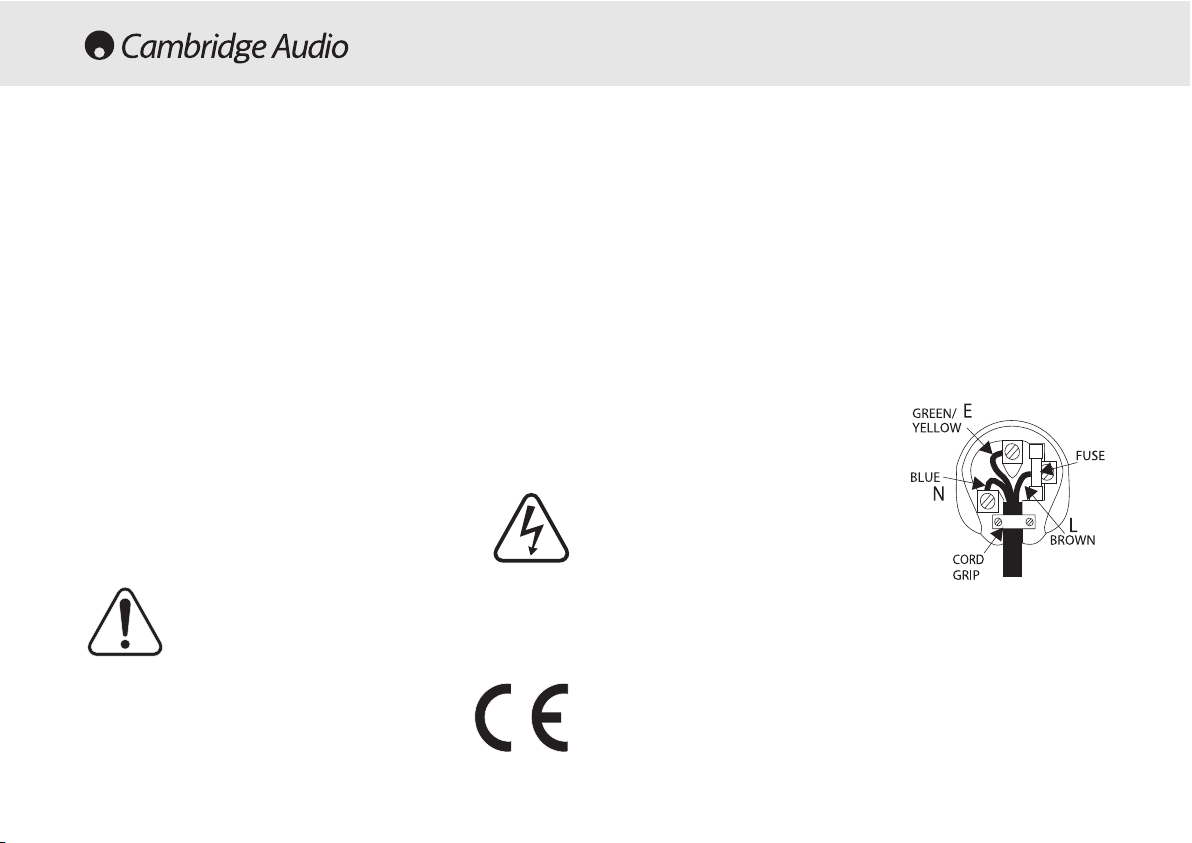
Plug ffitting iinstructions ((UK only)
The cord supplied with this appliance is factory fitted with a 13A mains plug fitted
with a 3A fuse inside. If it is necessary to change the fuse, it is important that a 3A
one is used. If the plug needs to be changed because it is not suitable for your
socket, or becomes damaged, it should be cut off and an appropriate plug fitted
following the wiring instructions below. The plug must then be disposed of safely,
as insertion into a 13A socket is likely to cause an electrical hazard. Should it be
necessary to fit a 3-pin BS mains plug to the power cord the wires should be fitted
as shown in this diagram. The colours of the wires in the mains lead of this
appliance may not correspond with the coloured markings identifying the
terminals in your plug. Connect them as follows:-
The wire which is coloured BLUE must be
connected to the terminal which is marked
with the letter 'N' or coloured BLACK.
The wire which is coloured BROWN must be
connected to the terminal which is marked
with the letter 'L' or coloured RED
The wire which is coloured GREEN/YELLOW
must be connected to the terminal which is
marked with the letter 'E' or coloured
GREEN.
If your model does not have an earth wire,
then disregard this instruction.
If a 13 Amp (BS 1363) plug is used, a 3 Amp fuse must be fitted, or if any other
type of plug is used a 3 Amp or 5 Amp fuse must be fitted, either in the plug or
adaptor, or on the distribution board.
Checking tthe ppower ssupply rrating
For your own safety please read the following instructions carefully before
attempting to connect this unit to the mains.
Check that the rear of your unit indicates the correct supply voltage. If your mains
supply voltage is different, consult your dealer.
This unit is designed to operate only on the supply voltage and type that is
indicated on the rear panel of the unit. Connecting to other power sources may
damage the unit.
This equipment must be switched to Standby mode when not in use, unplugged if
not used for long periods of time, and must not be used unless correctly earthed.
To reduce the risk of electric shock, do not remove the unit's cover (or back). There
are no user serviceable parts inside. Refer servicing to qualified service personnel.
If the power cord is fitted with a moulded mains plug the unit must not be used if
the plastic fuse carrier is not in place. Should you lose the fuse carrier the correct
part must be reordered from your Cambridge Audio dealer.
The lightning flash with the arrowhead symbol within an equilateral
triangle is intended to alert the user to the presence of uninsulated
'dangerous voltage' within the product's enclosure that may be of
sufficient magnitude to constitute a risk of electric shock to
persons.
The exclamation point within an equilateral triangle is intended to
alert the user to the presence of important operating and
maintenance instructions in the service literature relevant to this
appliance.
This product complies with European Low Voltage (73/23/EEC)
and Electromagnetic Compatibility (89/336/EEC) Directives
when used and installed according to this instruction manual. For
continued compliance only Cambridge Audio accessories should
be used with this product and servicing must be referred to
qualified service personnel.
SAFETY PRECAUTIONS
Page 5

Amplifiers
5
Please take a moment to read these notes before installing your
amplifier, they will enable you to get the best performance and prolong
the life of the product.
This unit should be installed on a sturdy, level surface. Due to stray
magnetic fields turntables should not be located nearby due to
interference.
The unit requires ventilation above and below. Do not situate it on a rug
or other soft surface and do not obstruct the air inlet and outlet grilles
on the underside and top cover. Do not place in an enclosed area such
as a bookcase or in a cabinet.
This unit must not be exposed to dripping or splashing water or other
liquids. No objects filled with liquid, such as vases, shall be placed on
the unit. In the event, switch off immediately, disconnect from the mains
supply and contact your dealer for advice.
Do not route the power cable so that it can be walked upon or damaged
by other items near it.
Electronic audio components have a running in period of around a week
(if used several hours per day). This will allow the new components to
settle down, the sonic properties will improve over this time.
Do not plug a source component directly into a
power
amplifier unless it
has a variable output level.
Always turn a control amplifier on before a power amplifier.
Never turn on a power amplifier when no control amplifier is connected.
It is recommended that when bi-amping, the same type power amplifiers
are used.
If you do not intend to use this unit for a long period of time, switch it off
and unplug it from the mains socket.
To clean the unit, wipe it’s case with a moist, lint-free cloth. Do not use
any cleaning fluids containing alcohol, ammonia or abrasives. Do not
spray an aerosol at or near the amplifier.
These units are not user serviceable, never attempt to repair,
disassemble or reconstruct the unit if there seems to be a problem. A
serious electric shock could result if this precautionary measure is
ignored. In the event of a problem or failure, please contact your dealer.
REAR PANEL CONNECTIONS
Note: SSome ffeatures mmay nnot aapply tto aall mmodels. RRefer tto tthe ddiagram
on yyour aaccompanying OOwners’ CCertificate.
A & C SERIES (INTEGRATED & CONTROL AMPLIFIERS)
Ground cconnection
If you are connecting a turntable to your amplifier then its ground wire
should be attached to this point.
Aux/Phono
Connect any 'line level' source equipment to these sockets i.e. CD player
or DAB tuner. Alternatively a turntable can be connected, but first a
phono stage must be installed. Please contact your Cambridge Audio
dealer who can supply and install a phono stage to your amplifier.
These
inputs aare ffor aanalog aaudio ssignals oonly. TThey sshould nnot bbe cconnected
to tthe ddigital ooutput oof aa CCD pplayer oor aany oother ddigital ddevice.
AV/DVD/MD/Tape 22
Connect a video derived audio signal to these sockets, such as the
audio monitor / receiver or Television decoder. Alternatively, any line
level audio signal may be connected here, including a second tape deck
or MiniDisc player.
INSTALLATION
Page 6

6
CD
Connect the audio signal from a Compact Disc player to these sockets.
Alternatively, any line level audio signal may be connected here.
Tuner
Connect the audio signal cable from a radio tuner to this pair of sockets.
These iinputs aare ffor aanalog aaudio ssignals oonly. TThey sshould nnot bbe
connected tto tthe ddigital ooutput oof aa CCD pplayer oor aany oother ddigital ddevice.
Pre-oouts
Connect these sockets to the inputs on your P Series Power Amplifier(s).
Please refer to the Connecting Diagrams for details.
Loudspeaker cconnections
Connect the wires from your left channel loudspeaker to the LEFT + & terminals, and likewise the wires from the right channel loudspeaker to
the RIGHT + & - terminals. In each case the red terminal is the positive
output, and the black terminal is the negative input. Care should be
taken to ensure no stray strands of wire are shorting speaker outputs
together.
Please eensure tthat tthe sspeaker tterminals hhave bbeen ttightened
adequately tto pprovide aa ggood eelectrical cconnection. IIt iis ppossible ffor tthe
sound qquality tto bbe aaffected iif tthe sscrew tterminals aare lloose.
AC power ssocket
Once you have completed all connections to the amplifier, plug the AC
Power Cable into an appropriate mains socket. The amplifier is now
ready for use.
P SERIES (POWER AMPLIFIERS)
Input/Output
Connect either of these pairs of sockets to the PRE-OUT sockets on your
A-Series (where featured) or C-Series amplifiers. The second set of
sockets can be used to connect a further power amplifier. Please refer
to the Connecting Diagrams for details.
These ssockets aare wwired iin
parallel sso eeither ccan bbe uused ffor iinput oor ooutput.
Loudspeaker cconnections
Connect the wires from your left channel loudspeaker to the LEFT + & terminals, and likewise the wires from the right channel loudspeaker to
the RIGHT + & - terminals. In each case the red terminal is the positive
output, and the black terminal is the negative input. Care should be
taken to ensure no stray strands of wire are shorting speaker outputs
together.
Please eensure tthat tthe sspeaker tterminals hhave bbeen ttightened
adequately tto pprovide aa ggood eelectrical cconnection. IIt iis ppossible ffor tthe
sound qquality tto bbe aaffected iif tthe sscrew tterminals aare lloose.
AC power ssocket
Once you have completed all connections to the amplifier, plug the AC
Power Cable into an appropriate mains socket. The amplifier is now
ready for use.
Page 7

Amplifiers
7
Note: SSome ffeatures mmay nnot aapply tto aall mmodels. RRefer tto tthe ddiagram oon
your aaccompanying OOwners’ CCer
tificate.
PPoowweerr
This control switches the mains power to the amplifier ON and OFF.
BBaassss && TTrreebbllee
These controls allow subtle adjustments to the tonal balance of the sound.
In the central position these controls have no effect. These controls only
modify the sound through your loudspeakers and the PRE-OUT sockets
(where featured), they do not affect the signals sent through the TAPE OUT
connections. With a well produced CD and a good system the tone controls
are unnecessary and can be switched out. If the musical recording is of poor
quality and/or the loudspeakers/surroundings are lacking it may be
necessary to adjust the tone controls to compensate.
DDiirreecctt
This control gives the audio signal a more direct path to the power amplifier
stage of your amplifier, bypassing the tone control circuits for the purest
possible sound quality.
VVoolluummee
This control adjusts the overall volume of the sound for both left and right
loudspeakers and the PRE-OUT sockets (where featured). It has no effect on
the level of the signals fed to the TAPE OUT connections to your tape/MD
recorder. On some models the volume can also be controlled using the
supplied, or optional, remote control unit.
It iis aadvisable tto tturn tthe VVOLUME
control ffully aanti-cclockwise bbefore sswitching tthe aamplifier oon.
BBaallaannccee
This control allows you to adjust the relative output levels of the left and right
channels. In the central position the output from each channel is equal. This
control only modifies the sound through your loudspeakers and the PRE-OUT
sockets (where featured), it does not affect the signals sent through the TAPE
OUT connections to your tape/MD recorder.
RReemmoottee sseennssoorr
This sensor receives the infra-red signals from the remote control unit.
IInnppuutt sseelleeccttoorr
Rotate the input selector switch to select the source component that you
wish to listen to. The signal selected is also fed to the TAPE OUT sockets so
that it may be recorded.
TTaappee//MMDD MMoonniittoorr
This control lets you listen to the output signal from a tape recorder or signal
processor connected to the amplifier's TAPE IN sockets. When TAPE/MD
MONITOR is selected, the source component chosen by the INPUT SELECTOR
continues to be routed to the TAPE OUT sockets for recording or processing.
CONNECTING
When designing our amplifiers we have tried to include features that allow
you to connect your system in various ways. The inclusion of features such as
PRE-OUT and bi-wire loudspeaker sockets mean that you can configure your
system depending on your requirements. The diagrams over the next few
pages are designed to make connection easy.
BBii-wwiirriinngg
If your loudspeakers are equipped with two sets of terminals, then it is
possible to connect them in the bi-wire configuration (see figures 3 & 5). Biwiring sends the bass and treble frequencies down separate speaker cables,
resulting in a clearer, more focussed sound.
BBii-aammppiinngg
If your amplifier is equipped with PRE-OUT sockets and your loudspeakers
have two sets of terminals then it is possible to bi-amp your system using a
further power amplifier (see figures 4, 6 & 7). Bi-amping uses two amplifiers
to drive the bass and treble units in the loudspeakers independently,
resulting in even greater clarity coupled with improved control and dynamics.
OPERATING INSTRUCTIONS
Page 8

8
FIGURE 1
INTEGRATED AMPLIFIER BASIC CONNECTIONS
(A1 SERIES)
FIGURE 2
INTEGRATED AMPLIFIER BASIC CONNECTIONS
(A5 SERIES)
Page 9

Amplifiers
9
FIGURE 4
BI-WIRING WITH AN INTEGRATED AMPLIFIER AND
BI-WIRABLE LOUDSPEAKERS (A1 SERIES)
FIGURE 3
CONTROL & POWER AMPLIFIER BASIC CONNECTIONS
Page 10

FIGURE 6
BI-AMPING WITH AN INTEGRATED AMPLIFIER AND
BI-WIRABLE LOUDSPEAKERS (A1 SERIES)
FIGURE 5
BI-WIRING WITH AN INTEGRATED AMPLIFIER AND
BI-WIRABLE LOUDSPEAKERS (A5 SERIES)
10
Page 11

FIGURE 7
BI-AMPING WITH AN INTEGRATED AMPLIFIER AND
BI-WIRABLE LOUDSPEAKERS (A5 SERIES)
FIGURE 8
BI-WIRING WITH A CONTROL/POWER COMBINATION
Amplifiers
11
Page 12

12
FIGURE 7
BI-AMPING WITH A CONTROL/POWER COMBINATION
ALTERNATIVE CONNECTIONS
FIGURE 9
BI-AMPING WITH A CONTROL/POWER COMBINATION
Page 13

13
There iis nno ppower
Ensure the AC power cord is connected securely.
Ensure the plug is fully inserted into the wall socket and is switched on
Check fuse in the mains plug or adaptor
There iis nno ssound
Check that source component is properly connected
Check that 'TAPE/MD MONITOR' is in the correct position
Check that your speakers are properly connected
There iis nno ssound oon oone cchannel
Ensure that balance control is in the correct position
Check speaker connections
Check interconnects
There iis aa lloud bbuzz oor hhum
Check turntable or tone arm for ground and connection lead fault
Ensure no interconnects are loose or defective
Ensure that your tape deck/turntable is not too close to the amplifier
Unable tto mmake oor pplay ttape rrecordings
Check that TAPE/MD IN and REC OUT have been connected correctly
There iis wweak bbass oor ddiffused sstereo iimaging
Ensure that speakers are not wired out of phase
Sound iis ddistorted
Ensure that your volume control is not set too high
TROUBLESHOOTING
540A/640A Integrated amplifer
Page 14

14
Cambridge Audio dealer, or authorised service agent which is authorised
to do Cambridge Audio warranty work. Any unauthorised repairs will void
this Warranty. This Warranty does not cover products sold AS IS or WITH
ALL FAULTS.
REPAIRS OR REPLACEMENTS AS PROVIDED UNDER THIS WARRANTY
ARE THE EXCLUSIVE REMEDY OF THE CONSUMER. CAMBRIDGE AUDIO
SHALL NOT BE LIABLE FOR ANY INCIDENTAL OR CONSEQUENTIAL
DAMAGES FOR BREACH OF ANY EXPRESS OR IMPLIED WARRANTY IN
THIS PRODUCT. EXCEPT TO THE EXTENT PROHIBITED BY LAW, THIS
WARRANTY IS EXCLUSIVE AND IN LIEU OF ALL OTHER EXPRESS AND
IMPLIED WARRANTIES WHATSOEVER INCLUDING, BUT NOT LIMITED TO,
THE WARRANTY OF MERCHANTABILITY AND FITNESS FOR A PRACTICAL
PURPOSE.
Some countries and US states do not allow the exclusion or limitation of
incidental or consequential damages or implied warranties so the above
exclusions may not apply to you. This Warranty gives you specific legal
rights, and you may have other statutory rights, which vary from state to
state or country to country.
Cambridge Audio warrants this product to be free from defects in
materials and workmanship (subject to the terms set forth below).
Cambridge Audio will repair or replace (at Cambridge Audio's option) this
product or any defective parts in this product. Warranty periods may vary
from country to country. If in doubt consult your dealer and ensure that
you retain proof of purchase.
To obtain warranty service, please contact the Cambridge Audio
authorised dealer from which you purchased this product. If your dealer
is not equipped to perform the repair of your Cambridge Audio product,
it can be returned by your dealer to Cambridge Audio or an authorised
Cambridge Audio service agent. You will need to ship this product in
either its original packaging or packaging affording an equal degree of
protection.
Proof of purchase in the form of a bill of sale or receipted invoice, which
is evidence that this product is within the warranty period, must be
presented to obtain warranty service.
This Warranty is invalid if (a) the factory-applied serial number has been
altered or removed from this product or (b) this product was not
purchased from a Cambridge Audio authorised dealer. You may call
Cambridge Audio or your local country Cambridge Audio distributor to
confirm that you have an unaltered serial number and/or you purchased
from a Cambridge Audio authorised dealer.
This Warranty does not cover cosmetic damage or damage due to acts
of God, accident, misuse, abuse, negligence, commercial use, or
modification of, or to any part of, the product. This Warranty does not
cover damage due to improper operation, maintenance or installation,
or attempted repair by anyone other than Cambridge Audio or a
LIMITED WARRANTY
Page 15

540A/640A Integrated amplifer
15
Page 16

Amplifiers
Part No. AP10513/4
www.cambridge-aaudio.com
 Loading...