

Cambium Networks XN16, XN8, XN12 Users Manual

Wi-Fi Array
write privileges on the Array (i.e., the new user will be able to change
the configuration of the Array). The default admin user is deleted.
b. New Admin Password: If desired, enter a new administration
password for managing this Array. Choose a password that is not
obvious, and one that you can remember. If you forget your
password, you must reset the Array to its factory defaults so that the
password is reset to admin (its default setting).
c. Confirm Admin Password: If you entered a new administration
password, confirm the new password here.
10. Time and Date Settings: This section specifies an optional time (NTP -
Network Time Protocol) server or modifies the system time if you’re not
using a server.
a. Time Zone: Select your time zone from the choices available in the
pull-down list.
b. Auto Adjust Daylight Savings: If you are not using NTP, check this
box if you want the system to adjust for daylight savings
automatically, otherwise leave this box unchecked (default).
c. Use Network Time Protocol: Check this box if you want to use an
NTP server to synchronize the Array’s clock. This ensures that Syslog
time-stamping is maintained across all units. Without an NTP server
assigned (no universal clock), each Array will use its own internal
clock and stamp times accordingly, which may result in
discrepancies. If you check Yes, the NTP server fields are displayed. If
you don’t want to use an NTP server, leave this box unchecked
(default) and set the system time on the Array manually.
d. NTP Primary Server: If you are using NTP, enter the IP address or
domain name of the NTP server.
e. NTP Secondary Server: Enter the IP address or domain name of an
optional secondary NTP server to be used in case the Array is unable
to contact the primary server.
138 Configuring the Wi-Fi Array

Wi-Fi Array
LED on
f. Set Time (hrs:min:sec): If you are not using NTP, check this box if
g. Set Date (month/day/year): If you are not using NTP, check this box if
11. IAP Settings:
Enable/Configure All IAPs: Click on the Execute button to enable and
auto configure all IAPs (a message displays the countdown time—in
seconds—to complete the auto-configuration task). When an IAP is
enabled, its LED is switched on.
you want to adjust the current system time. When the box is checked,
the time fields become active. Enter the revised time (hours, minutes,
seconds, am/pm) in the corresponding fields. If you don’t want to
adjust the current time, this box should be left unchecked (default).
you want to adjust the current system date. When the box is checked,
the date fields become active. Enter the revised date (month, day and
year) in the corresponding fields. If you don’t want to adjust the
current date, this box should be left unchecked (default).
Figure 88. LEDs are Switched On
12. Click on the Apply button to apply the new settings to this session, or
click Save to apply your changes and make them permanent.
This ends the Express Setup procedure.
Configuring the Wi-Fi Array 139

Wi-Fi Array
Network
This is a status only window that provides a snapshot of the configuration
settings currently established for the 10/100 Ethernet 0 interface and the Gigabit 1
and Gigabit 2 interfaces. DNS Settings and CDP Settings (Cisco Discovery
Protocol) are summarized as well. You must go to the appropriate configuration
window to make changes to any of the settings displayed here (configuration
changes cannot be made from this window). You can click on any item in the
Interface column to “jump” to the associated configuration window.
Figure 89. Network Interfaces
WMI windows that allow you to change or view configuration settings associated
with the network interfaces include:
z “Network Interfaces” on page 141
z “DNS Settings” on page 148
z “CDP Settings” on page 149
See Also
DNS Settings
Network Interfaces
Network Status Windows
Spanning Tree Status
Network Statistics
140 Configuring the Wi-Fi Array

Wi-Fi Array
Network Interfaces
This window allows you to establish configuration settings for the 10/100 Fast
Ethernet interface and the Gigabit 1 and Gigabit 2 interfaces.
Figure 90. Network Settings
#
Configuring the Wi-Fi Array 141
Gigabit 2 settings will “mirror” Gigabit 1 settings (except for MAC
addresses) and cannot be configured separately.
Wi-Fi Array
Serial
Fast Ethernet
Gigabit 1
Gigabit 2
When finished making changes, click on the Apply button to apply the new
settings to this session, or click Save to apply your changes and make them
permanent.
Network Interface Ports
The following diagram shows the location of each network interface port on the
underside of the Array.
Procedure for Configuring the Network Interfaces
Configure the Fast Ethernet and Gigabit 1 network interfaces (some Gigabit 2
settings cannot be configured separately and will mirror Gigabit 1). The fields for
each of these interfaces are the same, and include:
142 Configuring the Wi-Fi Array
Figure 91. Network Interface Ports
1. Enable Interface: Choose Ye s to enable this network interface (Fast
Ethernet, Gigabit 1 or Gigabit 2), or choose No to disable the interface.

Wi-Fi Array
2. LED Indicator: Choose Enabled to allow the LED for this interface to
blink with traffic on the port, or choose Disabled to turn the LED off.
The LED will still light during the boot sequence, then turn off. This
option is only available for the Gigabit interfaces.
3. Allow Management on Interface: Choose Ye s to allow management of
this Array via the selected network interface, or choose No to deny all
management privileges for this interface. This option is only available for
the Gigabit interfaces—management is always enabled on the 10/100
interface (sometimes called the Management Port).
4. Auto Negotiate: This feature allows the Array to negotiate the best
transmission rates automatically. Choose Yes to enable this feature, or
choose No to disable this feature—the default is enabled. If you disable
the Auto Negotiate feature, you must define the Duplex and Speed
options manually (otherwise these options are not available).
a. Duplex: Data is transmitted in two directions simultaneously (for
example, a telephone is a full-duplex device because both parties can
talk and be heard at the same time). Half-duplex allows data
transmission in one direction at a time only (for example, a walkietalkie is a half-duplex device. If the Auto-Negotiate feature is
disabled, you can manually choose Half or Full duplex for your data
transmission preference.
b. Speed: If the Auto-Negotiate feature is disabled, you can manually
choose the desired data transmission speed from the pull-down list. If
configuring the Fast Ethernet interface the options are 10 Megabit or
100 Megabit. If configuring the Gigabit 1 or Gigabit 2 interfaces the
options are 100 Megabit or Gigabit.
5. Port mode: Select the desired behavior for the gigabit Ethernet ports from
the following options:
a. Active Backup (gig1/gig2 failover to each other)—This mode
provides fault tolerance and is the default mode. Gigabit 1 acts as the
primary link. Gigabit2 is the backup link and is passive. Gigabit2
assumes the IP properties of Gigabit1. If Gigabit 1 fails the Array
Configuring the Wi-Fi Array 143
Wi-Fi Array
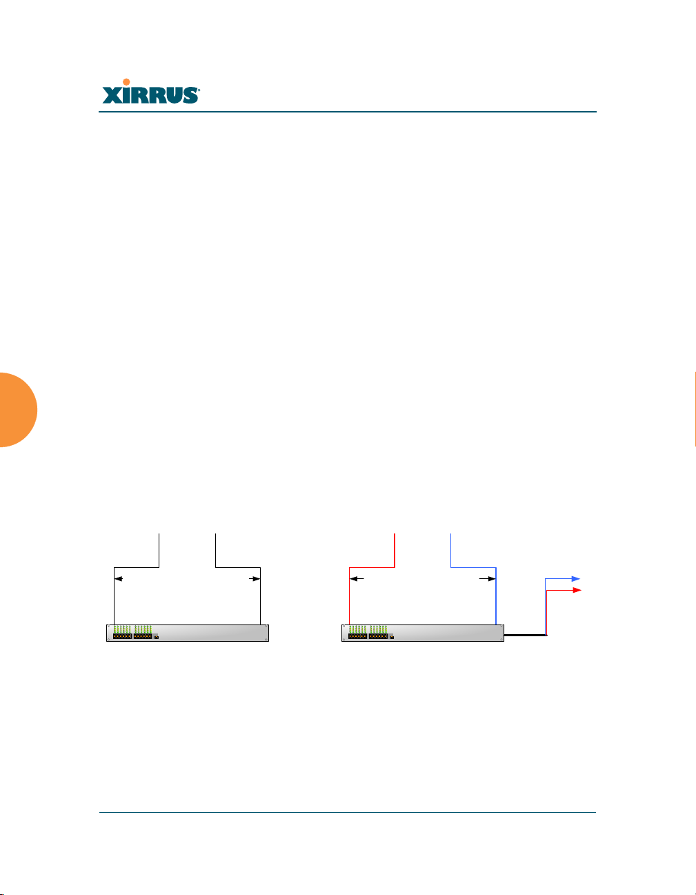
Gig1 Gig2
Primary Link
Secondary Link :
carries all traffic
if primary fails
Switch
Gig1 Gig2
Switch
Links split traffic based on
destination address, using
802.3ad link aggregation
Destinations
(a) Active backup (b) Aggregate using 802.3ad
automatically fails over to Gigabit2. When a failover occurs in this
mode, Gigabit2 issues gratuitous ARPs to allow it to substitute for
Gigabit1 at Layer 3 as well as Layer 2. See Figure 92 (a).
b. Aggregate Traffic from gig1 & gig2 using 802.3ad—The Array sends
network traffic across both gigabit ports to increase link speed to the
network. Both ports act as a single logical interface (trunk), using a
load balancing algorithm to balance traffic across the ports.
The destination IP address of a packet is used to determine its
outgoing adapter. For non-IP traffic (such as ARP), the last byte of the
destination MAC address is used to do the calculation. The network
switch must also support 802.3ad. If a port fails, the trunk degrades
gracefully—the other port still transmits. See Figure 92 (b).
Figure 92. Port Modes (a-b)
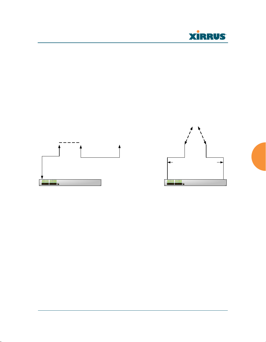
c. Bridge traffic between gig1 & gig2—Traffic received on Gigabit1 is
transmitted by Gigabit2; similarly, traffic received on Gigabit2 is
transmitted by Gigabit1. This allows the Array to act as a wired
bridge and allows Arrays to be daisy-chained and still maintain
144 Configuring the Wi-Fi Array
wired connectivity. See Figure 93 (c).
Wi-Fi Array
Gig1 Gig2
Switch
Gig1 and Gig2 are bridged.
Traffic received on either link
is repeated to the other
Gig1 Gig2
Gig1 Gig2
Switch
Received wireless traffic is
sent to both links
Traffic from either link is
processed for transmission
(c) Bridge traffic (d) Transmit on both ports
d. Transmit Traffic on both gig1 & gig2—Transmits incoming traffic on
both Gigabit1 and Gigabit2. Any traffic received on Gigabit1 or
Gigabit2 is sent to the onboard processor. This mode provides fault
tolerance. See Figure 93 (d).
Configuring the Wi-Fi Array 145
Figure 93. Port Modes (c-d)
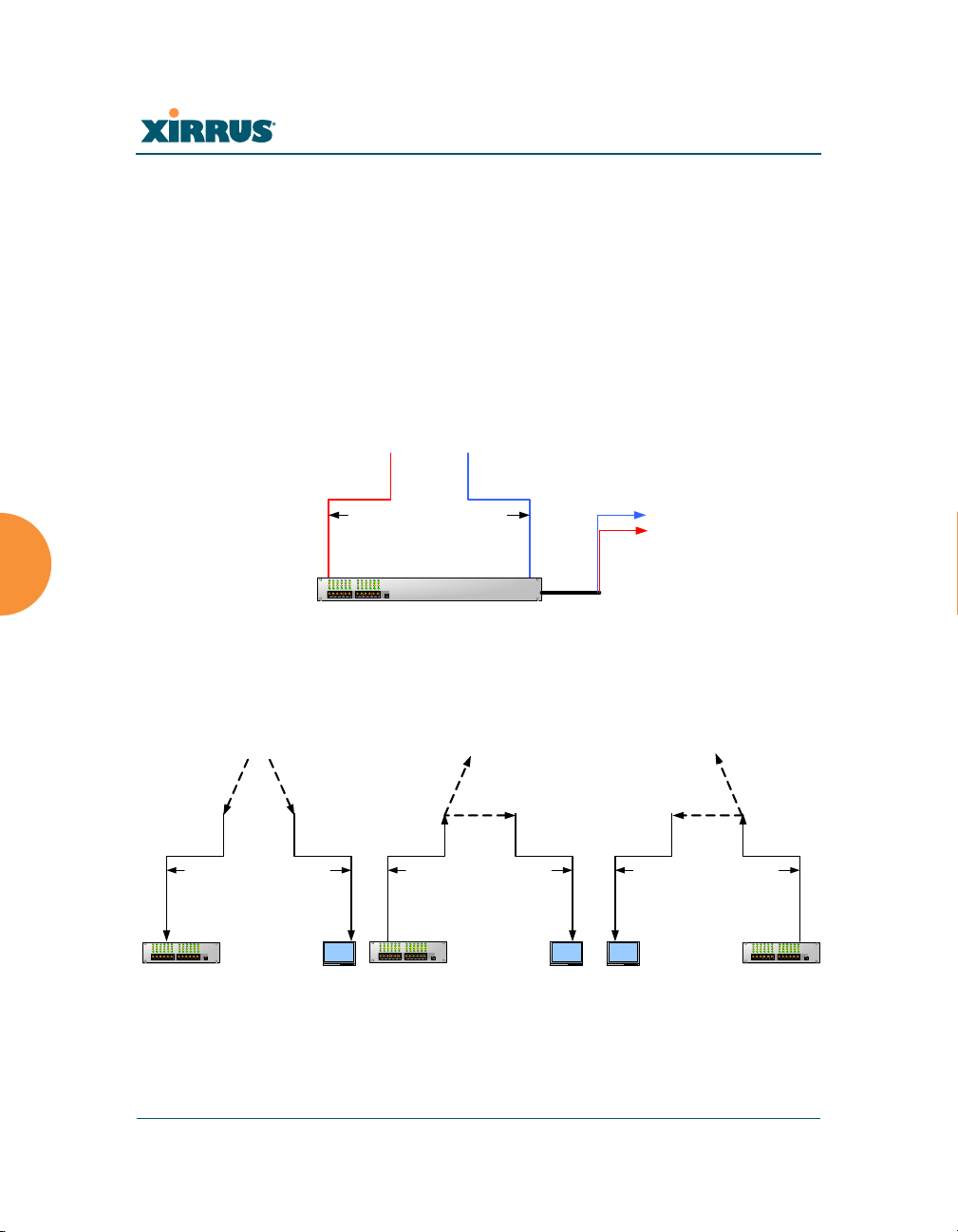
e. Load balance traffic between gig1 & gig2—This option provides
trunking, similar to option (b)—Aggregate Traffic from gig1 & gig2
using 802.3ad, but it uses a different load balancing algorithm to
determine the outgoing gigabit port. The outgoing port used is based
on an exclusive OR of the source and destination MAC address. Like
option (b), this mode also provides load balancing and fault
tolerance. See Figure 94 (e).
f. Mirror traffic on both gig1 & gig2—all traffic received on the Array
is transmitted out both Gigabit1 and Gigabit2. All traffic received on
Gigabit1 is passed on to the onboard processor as well as out
Gigabit2. All traffic received on Gigabit2 is passed on to the onboard
processor as well as out Gigabit1. This allows a network analyzer to
be plugged into one port to capture traffic for troubleshooting, while
Wi-Fi Array
Gig1 Gig2
Switch
Array load balances outgoing
traffic based on source and
destination address
Destinations
Gig1 Gig2
Received wireless traffic is
sent to both links
Gig1 Gig2
Traffic from Gig1 is processed
for wireless transmission and
copied to Gig2
Gig1 Gig2
Traffic from Gig2 is processed
for wireless transm i ssion and
copied to Gig 1
Switch
Switch
Switch
Network
Analyzer
Network
Analyzer
Network
Analyzer
(e) Load balance traffic
(f) Mirror traffic
the other port provides network connectivity for data traffic. See
Figure 94 (f).
146 Configuring the Wi-Fi Array
Figure 94. Port Modes (e-f)
 Loading...