

Page 1

XS
WirelessWireless
Wireless
WirelessWireless
User’s Guide
LAN ArrayLAN Array
LAN Array
LAN ArrayLAN Array
3900
3700
3500
March 17th, 2006
Page 2

Wireless LAN Array
XS-3900, XS-3700, XS-3500
All rights reserved. This document may not be reproduced or
disclosed in whole or in part by any means without the written
consent of Xirrus, Inc.
Part Number: 800-0006-001
(Revision E)
Page 3

Trademarks
is a trademark of Xirrus, Inc. All other trademarks and brand names
are marks of their respective holders.
Notices
FCC Notice
This device complies with Part 15 of the FCC Rules, with operation subject to the
following two conditions: (1) This device may not cause harmful interference, and
(2) this device must accept any interference received, including interference that
may cause unwanted operation.
This equipment has been tested and found to comply with the limits for a Class A
digital device, pursuant to Part 15 of the FCC rules. These limits are designed to
provide reasonable protection against harmful interference in a residential
installation. This equipment generates, uses and can radiate RF energy and, if not
installed and used in accordance with the instructions, may cause harmful
interference to radio communications. However, there is no guarantee that
interference will not occur in a particular installation. If this equipment does
cause harmful interference to radio or television reception, which can be
determined by turning the equipment off and on, the user is encouraged to try to
correct the interference by one or more of the following safety measures:
z Reorient or relocate the receiving antenna.
z Increase the separation between the equipment and the receiver.
z Consult the dealer or an experienced wireless technician for help.
Use of a shielded twisted pair (STP) cable must be used for all Ethernet
connections in order to comply with EMC requirements.
RF Radiation Hazard Warning
To ensure compliance with FCC RF exposure requirements, this device must be
installed in a location where the antennas of the device will have a minimum
distance of at least 25 cm (9.84 inches) from all persons. Using higher gain
antennas and types of antennas not certified for use with this product is not
allowed. The device shall not be co-located with another transmitter.
Page 4

Non-Modification Statement
Unauthorized changes or modifications to the device are not permitted. Use only
the supplied internal antenna, or external antennas supplied by the manufacturer.
Modifications to the device will void the warranty and may violate FCC
regulations. Please go to the Xirrus Web site for a list of all approved antennas.
Indoor Use
This product has been designed for indoor use. Operation of channels in the
5150MHz to 5250MHz band is permitted indoors only to reduce the potential for
harmful interference to co-channel mobile satellite systems.
Maximum Antenna Gain
Currently, the maximum antenna gain for external antennas is limited to 5.2dBi
for operation in the 2400MHz to 2483.5MHz, 5150MHz to 5250MHz and
5725MHz to 5825MHz bands. The antenna gains must not exceed maximum EIRP
limits set by the FCC / Industry Canada.
High Power Radars
High power radars are allocated as primary users (meaning they have priority) in
the 5150MHz to 5250MHz and 5650MHz to 5850MHz bands. These radars could
cause interference and/or damage to LELAN devices used in Canada.
Industry Canada Notice and Marking
This Class A digital apparatus complies with Canadian ICES-003.
Cet appareil numérique de la classe A est conforme à la norme NMB-003 du Canada.
The term “IC:” before the radio certification number only signifies that Industry
Canada technical specifications were met.
To reduce potential radio interference to other users, the antenna type and its gain
should be so chosen that the equivalent isotropically radiated power (EIRP) is not
more than that required for successful communication.
Page 5

EU Directive 1999/5/EC Compliance Information
This section contains compliance information for the Xirrus Wireless LAN Array
family of products, which includes the XS-3900, XS-3700 and XS-3500. The
compliance information contained in this section is relevant to the European
Union and other countries that have implemented the EU Directive 1999/5/EC.
Declaration of Conformity
Cesky [Czech] Toto zahzeni je v souladu se základnimi požadavky a
ostatnimi odpovidajcimi ustano veni mi Sm
1999/5/EC.
Dansk [Danish] Dette udstyr er i overensstemmelse med de
væsentlige krav og andre relevante bestemmelser i
Direktiv 1999/5/EF.
Deutsch [German] Dieses Gerat entspricht den grundlegenden
Anforderungen und den weiteren entsprechenden
Vorgaben der Richtinie 1999/5/EU.
Eesti [Estonian] See seande vastab direktiivi 1999/5/EU olulistele
nöuetele ja teistele as jakohastele sätetele.
English This equipment is in compliance with the essential
requirements and other relevant provisions of
Directive 1999/5/EC.
Č
rnice
Español [Spain] Este equipo cump le con los requisitos esenciales asi
como con otras disposiciones de la Directiva 1999/5/
CE.
ǼȜȜȘȞȣțȘ [Greek] ǹȣIJȩȗ Ƞ İȟȠʌȜIJıµȩȗ İȓȞĮȚ ıİ ıȣµµȩȡijȦıȘ µİIJȚȗ
ȠȣıȚȫįİȚȗ ĮʌĮȚIJȒıİȚȗ țĮȚ ȪȜȜİȗ ıȤİIJȚțȑȗ įȚĮIJȐȟİȚȗ IJȘȗ
ȅįȘȖȚĮȗ 1999/5/EC.
Français [French] Cet appareil est conforme aux exigences essentielles
et aux autres dispositions pertinentes de la Directive
1999/5/EC.
Ď
slenska [Icelandic]
Þetta tæki er samkvæmt grunnkröfum og öðrum
viðeigandi ákvæðum Tilskipunar 1999/5/EC.
Page 6

Italiano [Italian] Questo apparato é conforme ai requisiti essenziali ed
agli altri principi sanciti dalla Direttiva 1999/5/CE.
Latviski [Latvian] ŠƯ iekƗrta atbilst DirektƯvas 1999/5/EK bnjtiskajƗ
prasƯbƗm un citiem ar to saistƯtajiem noteikumiem.
Lietuviǐ [Lithuanian] Šis Ƴrenginys tenkina 1995/5/EB Direktyvos
esminius reikalavimus ir kitas šios direktyvos
nuostatas.
Nederlands [Dutch] Dit apparant voldoet aan de essentiele eisen en
andere van toepassing zijnde bepalingen van de
Richtlijn 1995/5/EC.
Malti [Maltese] Dan l-apparant huwa konformi mal-htigiet essenzjali
u l-provedimenti l-o
5/EC.
Margyar [Hungarian] Ez a készülék teljesiti az alapvetö követelményeket
és más 1999/5/EK irányelvben meghatározott
vonatkozó rendelkezéseket.
Norsk [Norwegian] Dette utstyret er i samsvar med de grunnleggende
krav og andre relevante bestemmelser i EU-direktiv
1999/5/EF.
hra rilevanti tad-Direttiva 1999/
Polski [Polish] Urządzenie jest zgodne z ogólnymi wymaganiami
oraz sczególnymi mi warunkami okreĞlony mi
Dyrektywą. UE:1999/5/EC.
Portuguès [Portugese] Este equipamento está em conformidade com os
requisitos essenciais e outras provisões relevantes da
Directiva 1999/5/EC.
Slovensko [Slovenian] Ta naprava je skladna z bistvenimi zahtevami in
ostalimi relevantnimi popoji Direktive 1999/5/EC.
Slovensky [Slovak] Toto zariadenie je v zhode so základnými
požadavkami a inými prislušnými nariadeniami
direktiv: 1999/5/EC.
Page 7

Suomi [Finnish] Tämä laite täyttää direktiivin 1999/5//EY olennaiset
vaatimukset ja on siinä asetettujen muiden laitetta
koskevien määräysten mukainen.
Svenska [Swedish] Denna utrustning är i överensstämmelse med de
väsentliga kraven och andra relevanta bestämmelser
i Direktiv 1999/5/EC.
Assessment Criteria
The following standards were applied during the assessment of the product
against the requirements of the Directive 1999/5/EC:
z Radio: EN 301 893 and EN 300 328 (if applicable)
z EMC: EN 301 489-1 AND en 301 489-17
z Safety: EN 50371 to EN 50385
CE Marking
For the Xirrus Wireless LAN Array (XS-3900, XS-3700 and XS-3500), the CE mark
and Class-2 identifier opposite are affixed to the equipment and its packaging:
Page 8
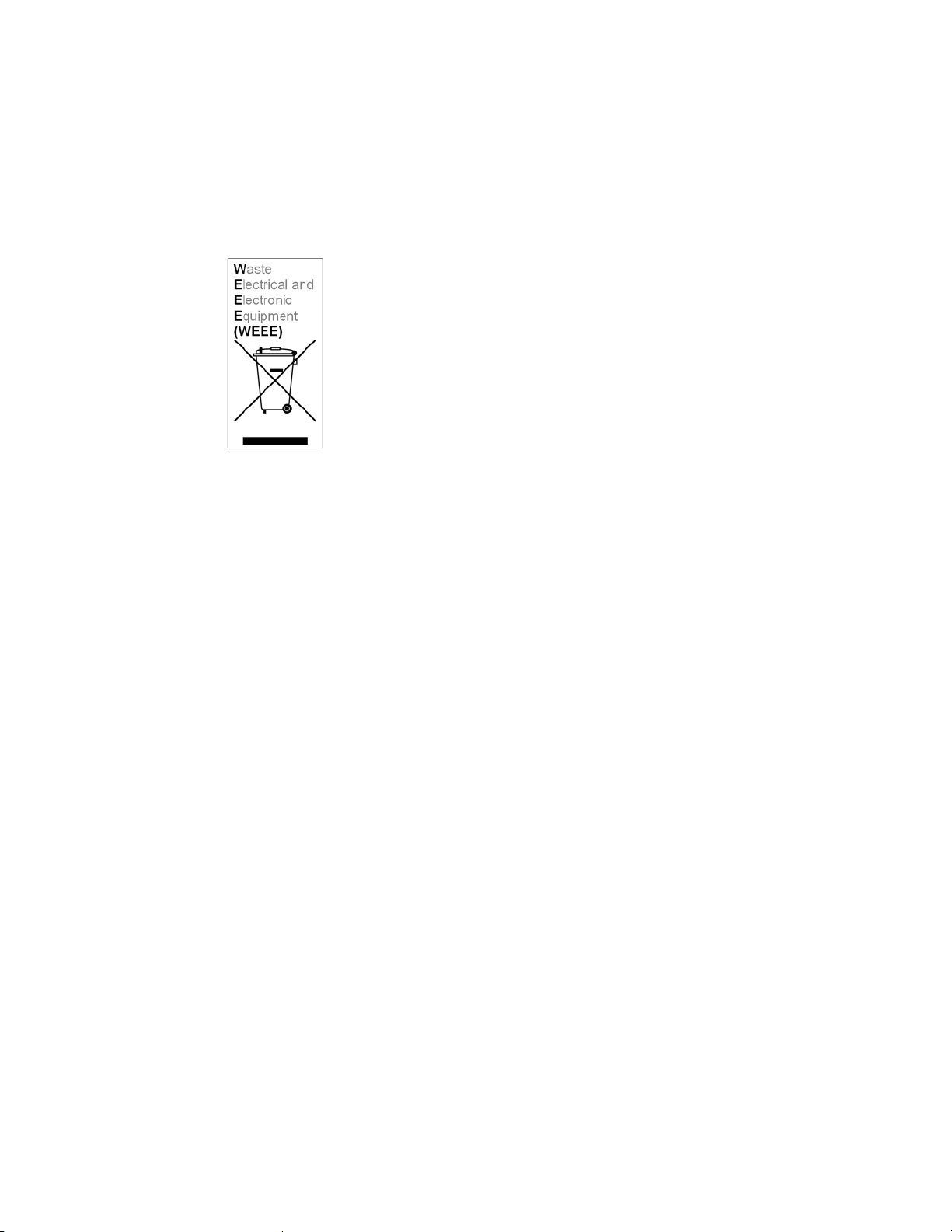
WEEE Compliance
z Natural resources were used in the production of
this equipment.
z This equipment may contain hazardous substances
that could impact the health of the environment.
z In order to avoid harm to the environment and
consumption of natural resources, we encourage
you to use appropriate take-back systems when
disposing of this equipment.
z The appropriate take-back systems will reuse or
recycle most of the materials of this equipment in a
way that will not harm the environment.
z The crossed-out wheeled bin symbol (in
accordance with European Standard EN 50419)
invites you to use those take-back systems and
advises you not to combine the material with
refuse destined for a land fill.
z If you need more information on collection, re-use
and recycling systems, please contact your local or
regional waste administration.
z Please contact Xirrus for specific information on the
environmental performance of our products.
Page 9
National Restrictions
In the majority of the EU and other European countries, the 2.4 GHz and 5 GHz
bands have been made available for the use of Wireless LANs. The following table
provides an overview of the regulatory requirements in general that are
applicable for the 2.4 GHz and 5 GHz bands.
Frequency Band
(MHz)
Max Power Level
(EIRP) (mW)
Indoor
ONLY
Outdoor
ONLY
2400–2483.5 100 X X**
5150–5350* 200 X N/A
5470–5725* 1000 X X
*Dynamic frequency selection and Transmit Power Control is required in these
frequency bands.
**France is indoor use only in the upper end of the band.
The requirements for any country may change at any time. Xirrus recommends
that you check with local authorities for the current status of their national
regulations for both 2.4 GHz and 5 GHz wireless LANs.
The following countries have additional requirements or restrictions than those
listed in the above table:
Belgium
The Belgian Institute for Postal Services and Telecommunications (BIPT) must
be notified of any outdoor wireless link having a range exceeding 300 meters.
Xirrus recommends checking at
www.bipt.be for more details.
Draadloze verbindingen voor buitengebruik en met een reikwijdte van meer dan 300
meter dienen aangemeld te worden bij het Belgisch Instituut voor postdiensten en
telecommunicatie (BIPT). Zie
www.bipt.be voor meer gegevens.
Les liasons sans fil pour une utilisation en extérieur d’une distance supérieure à 300
mèters doivent être notifiées à l’Institut Belge des services Postaux et des
Télécommunications (IBPT). Visitez
www.bipt.be pour de plus amples détails.
Page 10

France
The use of the band from 5470 MHz to 5725 MHz is not allowed in France.
The band from 5150 MHz to 5350 MHz can only be used indoors. If the
product is used outdoors, the use of any 5 GHz frequency is not allowed, and
power output is restricted in some portions of the 2.4 GHz band. Refer to the
following table or go to
L’utilisation de la bande 5470 MHz à 5725 MHz n’est pas autorisée en France. La
bande de 5150 MHz à 5350 MHz ne peut être utilisée qu’ à l’intérieur d’un bâtiment.
Dans le cas d’une utilisation en extérieur aucune fréquence dans le bandes des 5 GHz
n’est permise, tandis que la puissance est limitée dans certaines parties de la bande
des 2.4 GHz. Reportez-vous à la suivre table ou visitez www.art-telecom.fr pour de
plus amples détails.
The following table shows the applicable power levels for 2.4 GHz and 5 GHz
in France (Puissances utilisables dans les bandes 2.4 GHz et 5 GHz en France).
www.art-telecom.fr for more details.
Location
Indoor
(Intérieur)
Outdoor
(Extérieur)
Frequency Range
(MHz)
2400–2483.5
5150–5350
5470–5725
2400–2454
2454–2483.5
5150–5350
5470–5725
Power (EIRP)
100 mW (20 dBm)
200 mW (23 dBm)
Not allowed (Interdit)
100 mW (20 dBm)
10 mW (10 dBm)
Not allowed (Interdit)
Not allowed (Interdit)
Page 11

Greece
A license from EETT is required for the outdoor operation in the 5470 MHz to
5725 MHz band. Xirrus recommends checking www.eett.gr for more details.
З дз йпхсгȕȐйкф щнеощфесйкп спхуфз ж нзух нпф фщн 5470–5725 МЗz å éôñ åôȐéùíï
åôÜȐ ьЬдейȐ фзт ЕЕФФ, пх псзгеȕôȐé óôåñȐȐь у цщнз гн з фпх ГЕЕИБ.
есйууьфесет ле фпм сейещуфп www.eett.gr
Italy
This product meets the National Radio Interface and the requirements
specified in the National Frequency Allocation Table for Italy. Unless this
wireless LAN product is operating within the boundaries of the owner’s
property, its use requires a “general authorization.” please check with
www.communicazioni.it/it/ for more details.
Questo prodotto é conforme alla specifiche di Interfaccia Radio Nazionali e rispetta il
Piano Nazionale di ripartizione delle frequenze in Italia. Se non viene installato
all’interno del proprio fondo, l’utilizzo di prodotti wireless LAN richiede una
“autorizzazione Generale.” Consultare www.communicazioni.it/it/ per maggiori
dettagli.
Noway, Switzerland and Liechtenstein
Although Norway, Switzerland and Liechtenstein are not EU member states,
the EU Directive 1999/5/EC has also been implemented in those countries.
Calculating the Maximum Output Power
The regulatory limits for maximum output power are specified in EIRP (radiated
power). The EIRP level of a device can be calculated by adding the gain of the
antenna used (specified in dBi) to the output power available at the connector
(specified in dBm).
Page 12

Antennas
The Xirrus Wireless LAN Array family of products employs integrated antennas
that cannot be removed and which are not user accessible. Nevertheless, as
regulatory limits are not the same throughout the EU, users may need to adjust
the conducted power setting for the radio to meet the EIRP limits applicable in
their country or region. Adjustments can be made from the product’s
management interface—either Web Management Interface (WMI) or Command
Line Interface (CLI).
Operating Frequency
The operating frequency in a wireless LAN is determined by the access point. As
such, it is important that the access point is correctly configured to meet the local
regulations. See National Restrictions in this section for more information.
If you still have questions regarding the compliance of Xirrus products or you
cannot find the information you are looking for, please contact us at:
Xirrus, Inc.
370 North Westlake Blvd, Suite 200
Westlake Village, CA 91362
USA
Tel: 1.805.497.0955
Fax: 1.805.449.1180
www.xirrus.com
Page 13

Safety Warnings
Safety Warnings
!
Read all user documentation before powering this device. All Xirrus
interconnected equipment should be contained indoors. This product is
not suitable for outdoor operation. Please verify the integrity of the
system ground prior to installing Xirrus equipment. Additionally,
verify that the ambient operating temperature does not exceed 50°C.
Explosive Device Proximity Warning
!
Do not operate the XS-3900/XS-3700/XS-3500 unit near unshielded
blasting caps or in an explosive environment unless the device has been
modified to be especially qualified for such use.
Lightning Activity Warning
!
Do not work on the XS-3900/XS-3700/XS-3500 or connect or disconnect
cables during periods of lightning activity.
Circuit Breaker Warning
!
The XS-3900/XS-3700/XS-3500 relies on the building’s installation for
over current protection. Ensure that a fuse or circuit breaker no larger
than 120 VAC, 15A (U.S.) or 240 VAC, 10A (International) is used on all
current-carrying conductors.
Translated safety warnings appear on the following page.
Page 14

Translated Safety Warnings
Avertissements de Sécurité
Sécurité
!
Lisez l'ensemble de la documentation utilisateur avant de mettre cet
appareil sous tension. Tous les équipements Xirrus interconnectés
doivent être installés en intérieur. Ce produit n'est pas conçu pour être
utilisé en extérieur. Veuillez vérifier l'intégrité de la terre du système
avant d'installer des équipements Xirrus. Vérifiez également que la
température de fonctionnement ambiante n'excède pas 50°C.
Proximité d'appareils explosifs
!
N'utilisez pas l'unité XS-3900/XS-3700/XS-3500 à proximité d'amorces
non blindées ou dans un environnement explosif, à moins que
l'appareil n'ait été spécifiquement modifié pour un tel usage.
Foudre
!
N'utilisez pas l'unité XS-3900/XS-3700/XS-3500 et ne branchez pas ou
ne débranchez pas de câbles en cas de foudre.
Disjoncteur
!
L'unité XS-3900/XS-3700/XS-3500 dépend de l'installation du bâtiment
pour ce qui est de la protection contre les surintensités. Assurez-vous
qu'un fusible ou qu'un disjoncteur de 120 Vca, 15 A (États-Unis) ou de
240 Vca, 10 A (International) maximum est utilisé sur tous les
conducteurs de courant.
Page 15

Software Warranty and License Agreement
THIS SOFTWARE LICENSE AGREEMENT (THE “AGREEMENT”) IS A LEGAL
AGREEMENT BETWEEN YOU (“CUSTOMER”) AND LICENSOR (AS DEFINED
BELOW) AND GOVERNS THE USE OF THE SOFTWARE INSTALLED ON THE
PRODUCT (AS DEFINED BELOW). IF YOU ARE AN EMPLOYEE OR AGENT
OF CUSTOMER, YOU HEREBY REPRESENT AND WARRANT TO LICENSOR
THAT YOU HAVE THE POWER AND AUTHORITY TO ACCEPT AND TO
BIND CUSTOMER TO THE TERMS AND CONDITIONS OF THIS AGREEMENT
(INCLUDING ANY THIRD PARTY TERMS SET FORTH HEREIN). IF YOU DO
NOT AGREE TO ALL OF THE TERMS OF THIS AGREEMENT RETURN THE
PRODUCT AND ALL ACCOMPANYING MATERIALS (INCLUDING ALL
DOCUMENTATION) TO THE RELEVANT VENDOR FOR A FULL REFUND OF
THE PURCHASE PRICE THEREFOR.
CUSTOMER UNDERSTANDS AND AGREES THAT USE OF THE SOFTWARE
SHALL BE DEEMED AN AGREEMENT TO THE TERMS AND CONDITIONS
GOVERNING SUCH SOFTWARE AND THAT CUSTOMER IS BOUND BY AND
BECOMES A PARTY TO THIS AGREEMENT.
1. Definitions
1.1 “Documentation” means the user manuals and all other all
documentation, instructions or other similar materials accompanying the
Software covering the installation, application, and use thereof.
1.2 “Licensor” means XIRRUS and its suppliers.
1.3 “Product” means a multi-radio access point containing four or more
distinct radios capable of simultaneous operation on four or more nonoverlapping channels.
1.4 “Software” means, collectively, each of the application and embedded
software programs delivered to Customer in connection with this
Agreement. For purposes of this Agreement, the term Software shall be
deemed to include any and all Documentation and Updates provided
with or for the Software.
1.5 “Updates” means any bug-fix, maintenance or version release to the
Software that may be provided to Customer from Licensor pursuant to
this Agreement or pursuant to any separate maintenance and support
agreement entered into by and between Licensor and Customer.
Page 16

2. Grant of Rights
2.1 Software. Subject to the terms and conditions of this Agreement, Licensor
hereby grants to Customer a perpetual, non-exclusive, nonsublicenseable, non-transferable right and license to use the Software
solely as installed on the Product in accordance with the accompanying
Documentation and for no other purpose.
2.2 Ownership. The license granted under Sections 2.1 above with respect to
the Software does not constitute a transfer or sale of Licensor's or its
suppliers' ownership interest in or to the Software, which is solely
licensed to Customer. The Software is protected by both national and
international intellectual property laws and treaties. Except for the
express licenses granted to the Software, Licensor and its suppliers retain
all rights, title and interest in and to the Software, including (i) any and all
trade secrets, copyrights, patents and other proprietary rights therein or
thereto or (ii) any Marks (as defined in Section 2.3 below) used in
connection therewith. In no event shall Customer remove, efface or
otherwise obscure any Marks contained on or in the Software. All rights
not expressly granted herein are reserved by Licensor.
2.3 Copies. Customer shall not make any copies of the Software but shall be
permitted to make a reasonable number of copies of the related
Documentation. Whenever Customer copies or reproduces all or any part
of the Documentation, Customer shall reproduce all and not efface any
titles, trademark symbols, copyright symbols and legends, and other
proprietary markings or similar indicia of origin (“Marks”) on or in the
Documentation.
Page 17

2.4 Restrictions. Customer shall not itself, or through any parent, subsidiary,
affiliate, agent or other third party (i) sell, rent, lease, license or
sublicense, assign or otherwise transfer the Software, or any of
Customer's rights and obligations under this Agreement except as
expressly permitted herein; (ii) decompile, disassemble, or reverse
engineer the Software, in whole or in part, provided that in those
jurisdictions in which a total prohibition on any reverse engineering is
prohibited as a matter of law and such prohibition is not cured by the fact
that this Agreement is subject to the laws of the State of California,
Licensor agrees to grant Customer, upon Customer's written request to
Licensor, a limited reverse engineering license to permit interoperability
of the Software with other software or code used by Customer; (iii) allow
access to the Software by any user other than by Customer's employees
and contractors who are bound in writing to confidentiality and non-use
restrictions at least as protective as those set forth herein; (iv) except as
expressly set forth herein, write or develop any derivative software or
any other software program based upon the Software; or (v) use any
computer software or hardware which is designated to defeat any copy
protection or other use limiting device, including any device intended to
limit the number of users or devices accessing the Product.
3. Limited Warranty and Limitation of Liability
3.1 Limited Warranty & Exclusions. Licensor warrants that the Software will
perform in substantial accordance with the specifications therefor set
forth in the Documentation for a period of ninety [90] days after
Customer's acceptance of the terms of this Agreement with respect to the
Software (“Warranty Period”). If during the Warranty Period the
Software does not perform as warranted, Licensor shall, at its option,
correct the relevant Software giving rise to such breach of performance or
replace such Software free of charge. THE FOREGOING ARE
CUSTOMER'S SOLE AND EXCLUSIVE REMEDIES FOR BREACH OF
THE FOREGOING WARRANTY. THE WARRANTY SET FORTH
ABOVE IS MADE TO AND FOR THE BENEFIT OF CUSTOMER ONLY.
The warranty will apply only if (i) the Software has been used at all times
and in accordance with the instructions for use set forth in the
Documentation and this Agreement; (ii) no modification, alteration or
addition has been made to the Software by persons other than Licensor or
Licensor's authorized representative; and (iii) the Software or Product on
which the Software is installed has not been subject to any unusual
electrical charge.
Page 18

3.2 DISCLAIMER. EXCEPT AS EXPRESSLY STATED IN THIS SECTION 3,
ALL ADDITIONAL CONDITIONS, REPRESENTATIONS, AND
WARRANTIES, WHETHER IMPLIED, STATUTORY OR OTHERWISE,
INCLUDING, WITHOUT LIMITATION, ANY IMPLIED WARRANTIES
OR CONDITIONS OF MERCHANTABILITY, FITNESS FOR A
PARTICULAR PURPOSE, SATISFACTORY QUALITY, ACCURACY,
AGAINST INFRINGEMENT OR ARISING FROM A COURSE OF
DEALING, USAGE, OR TRADE PRACTICE, ARE HEREBY
DISCLAIMED BY LICENSOR AND ITS SUPPLIERS. THIS DISCLAIMER
SHALL APPLY EVEN IF ANY EXPRESS WARRANTY AND LIMITED
REMEDY OFFERED BY LICENSOR FAILS OF ITS ESSENTIAL
PURPOSE. ALL WARRANTIES PROVIDED BY LICENSOR ARE
SUBJECT TO THE LIMITATIONS OF LIABILITY SET FORTH IN THIS
AGREEMENT.
3.3 HAZARDOUS APPLICATIONS. THE SOFTWARE IS NOT DESIGNED
OR INTENDED FOR USE IN HAZARDOUS ENVIRONMENTS
REQUIRING FAIL SAFE PERFORMANCE, SUCH AS IN THE
OPERATION OF A NUCLEAR FACILITY, AIRCRAFT NAVIGATION OR
COMMUNICATIONS SYSTEMS, AIR TRAFFIC CONTROLS OR OTHER
DEVICES OR SYSTEMS IN WHICH A MALFUNCTION OF THE
SOFTWARE WOULD RESULT IN FORSEEABLE RISK OF INJURY OR
DEATH TO THE OPERATOR OF THE DEVICE OR SYSTEM OR TO
OTHERS (“HAZARDOUS APPLICATIONS”). CUSTOMER ASSUMES
ANY AND ALL RISKS, INJURIES, LOSSES, CLAIMS AND ANY OTHER
LIABILITIES ARISING OUT OF THE USE OF THE SOFTWARE IN ANY
HAZARDOUS APPLICATIONS.
3.4 Limitation of Liability.
(a) TOTAL LIABILITY. NOTWITHSTANDING ANYTHING ELSE
HEREIN, ALL LIABILITY OF LICENSOR AND ITS SUPPLIERS
UNDER THIS AGREEMENT SHALL BE LIMITED TO THE
AMOUNT PAID BY CUSTOMER FOR THE RELEVANT
SOFTWARE, OR PORTION THEREOF, THAT GAVE RISE TO SUCH
LIABILITY OR ONE HUNDRED UNITED STATES DOLLARS
(US$100), WHICHEVER IS GREATER. THE LIABILITY OF
LICENSOR AND ITS SUPPLIERS UNDER THIS SECTION SHALL
BE CUMULATIVE AND NOT PER INCIDENT.
Page 19

(b) DAMAGES. IN NO EVENT SHALL LICENSOR, ITS SUPPLIERS OR
THEIR RELEVANT SUBCONTRACTORS BE LIABLE FOR (A) ANY
INCIDENTAL, SPECIAL, PUNITIVE OR CONSEQUENTIAL
DAMAGES, LOST PROFITS OR LOST OR DAMAGED DATA, OR
ANY INDIRECT DAMAGES, WHETHER ARISING IN CONTRACT,
TORT (INCLUDING NEGLIGENCE AND STRICT LIABILITY) OR
OTHERWISE OR (B) ANY COSTS OR EXPENSES FOR THE
PROCUREMENT OF SUBSTITUTE GOODS OR SERVICES IN EACH
CASE, EVEN IF LICENSOR OR ITS SUPPLIERS HAVE BEEN
INFORMED OF THE POSSIBILITY OF SUCH DAMAGES.
3.5 Exclusions. SOME JURISDICTIONS DO NOT PERMIT THE
LIMITATIONS OF LIABILITY AND LIMITED WARRANTIES SET
FORTH UNDER THIS AGREEMENT. IN THE EVENT YOU ARE
LOCATED IN ANY SUCH JURISDICTION, THE FOREGOING
LIMITATIONS SHALL APPLY ONLY TO THE MAXIMUM EXTENT
PERMITTED IN SUCH JURISDICTIONS. IN NO EVENT SHALL
THE FOREGOING EXCLUSIONS AND LIMITATIONS ON
DAMAGES BE DEEMED TO APPLY TO ANY LIABILITY BASED
ON FRAUD, WILLFUL MISCONDUCT, GROSS NEGLIGENCE OR
PERSONAL INJURY OR DEATH.
4. Confidential Information
4.1 Generally. The Software (and its accompanying Documentation)
constitutes Licensor's and its suppliers' proprietary and confidential
information and contains valuable trade secrets of Licensor and its
suppliers (“Confidential Information”). Customer shall protect the
secrecy of the Confidential Information to the same extent it protects its
other valuable, proprietary and confidential information of a similar
nature but in no event shall Customer use less than reasonable care to
maintain the secrecy of the Confidential Information. Customer shall not
use the Confidential Information except to exercise its rights or perform
its obligations as set forth under this Agreement. Customer shall not
disclose such Confidential Information to any third party other than
subject to non-use and non-disclosure obligations at least as protective of
a party's right in such Confidential Information as those set forth herein.
4.2 Return of Materials. Customer agrees to (i) destroy all Confidential
Information (including deleting any and all copies contained on any of
Customer's Designated Hardware or the Product) within fifteen (15) days
of the date of termination of this Agreement or (ii) if requested by
Licensor, return, any Confidential Information to Licensor within thirty
(30) days of Licensor's written request.
Page 20

5. Term and Termination
5.1 Te r m . Subject to Section 5.2 below, this Agreement will take effect on the
Effective Date and will remain in force until terminated in accordance
with this Agreement.
5.2 Termination Events. This Agreement may be terminated immediately
upon written notice by either party under any of the following
conditions:
(a) If the other party has failed to cure a breach of any material term or
condition under the Agreement within thirty (30) days after receipt of
notice from the other party; or
(b) Either party ceases to carry on business as a going concern, either
party becomes the object of the institution of voluntary or
involuntary proceedings in bankruptcy or liquidation, which
proceeding is not dismissed within ninety (90) days, or a receiver is
appointed with respect to a substantial part of its assets.
5.3 Effect of Termination.
(a) Upon termination of this Agreement, in whole or in part, Customer
shall pay Licensor for all amounts owed up to the effective date of
termination. Termination of this Agreement shall not constitute a
waiver for any amounts due.
(b) The following Sections shall survive the termination of this
Agreement for any reason: Sections 1, 2.2, 2.4, 3, 4, 5.3, and 6.
(c) No later than thirty (30) days after the date of termination of this
Agreement by Licensor, Customer shall upon Licensor's instructions
either return the Software and all copies thereof; all Documentation
relating thereto in its possession that is in tangible form or destroy the
same (including any copies thereof contained on Customer's
Designated Hardware). Customer shall furnish Licensor with a
certificate signed by an executive officer of Customer verifying that
the same has been done.
Page 21

6. Miscellaneous
If Customer is a corporation, partnership or similar entity, then the license to
the Software and Documentation that is granted under this Agreement is
expressly conditioned upon and Customer represents and warrants to
Licensor that the person accepting the terms of this Agreement is authorized
to bind such entity to the terms and conditions herein. If any provision of this
Agreement is held to be invalid or unenforceable, it will be enforced to the
extent permissible and the remainder of this Agreement will remain in full
force and effect. During the course of use of the Software, Licensor may
collect information on your use thereof; you hereby authorize Licensor to use
such information to improve its products and services, and to disclose the
same to third parties provided it does not contain any personally identifiable
information. The express waiver by either party of any provision, condition
or requirement of this Agreement does not constitute a waiver of any future
obligation to comply with such provision, condition or requirement.
Customer and Licensor are independent parties. Customer may not export or
re-export the Software or Documentation (or other materials) without
appropriate United States, European Union and foreign government licenses
or in violation of the United State's Export Administration Act or foreign
equivalents and Customer shall comply with all national and international
laws governing the Software. This Agreement will be governed by and
construed under the laws of the State of California and the United States as
applied to agreements entered into and to be performed entirely within
California, without regard to conflicts of laws provisions thereof and the
parties expressly exclude the application of the United Nations Convention
on Contracts for the International Sales of Goods and the Uniform Computer
Information Transactions Act (as promulgated by any State) to this
Agreement. Suits or enforcement actions must be brought within, and each
party irrevocably commits to the exclusive jurisdiction of, the state and
federal courts located in Ventura County, California. Customer may not
assign this Agreement by operation of law or otherwise, without the prior
written consent of Licensor and any attempted assignment in violation of the
foregoing shall be null and void. This Agreement cancels and supersedes all
prior agreements between the parties. This Agreement may not be varied
except through a document agreed to and signed by both parties. Any printed
terms and conditions contained in any Customer purchase order or in any
Licensor acknowledgment, invoice or other documentation relating to the
Software shall be deemed deleted and of no force or effect and any additional
typed and/or written terms and conditions contained shall be for
administrative purposes only, i.e. to identify the types and quantities of
Software to be supplied, line item prices and total price, delivery schedule,
and other similar ordering data, all in accordance with the provisions of this
Agreement.
Page 22

Hardware Warranty Agreement
PLEASE READ THIS AGREEMENT CAREFULLY BEFORE USING THIS
PRODUCT
BY USING THIS PRODUCT, YOU ACKNOWLDEGE THAT YOU HAVE READ
AND UNDERSTOOD ALL THE TERMS AND CONDITIONS OF THIS
AGREEMENT AND THAT YOU ARE CONSENTING TO BE BOUND BY THIS
AGREEMENT. IF YOU DO NOT AGREE TO ALL OF THE TERMS OF THIS
AGREEMENT, RETURN THE UNUSED PRODUCT TO THE PLACE OF
PURCHASE FOR A FULL REFUND.
LIMITED WARRANTY. Xirrus warrants that for a period of one year from the
date of purchase by the original purchaser (“Customer”): (i) the Xirrus Equipment
(“Equipment”) will be free of defects in materials and workmanship under
normal use; and (ii) the Equipment substantially conforms to its published
specifications. Except for the foregoing, the Equipment is provided AS IS. This
limited warranty extends only to Customer as the original purchaser. Customer's
exclusive remedy and the entire liability of Xirrus and its suppliers under this
limited warranty will be, at Xirrus' option, repair, replacement, or refund of the
Equipment if reported (or, upon request, returned) to the party supplying the
Equipment to Customer. In no event does Xirrus warrant that the Equipment is
error free or that Customer will be able to operate the Equipment without
problems or interruptions.
This warranty does not apply if the Equipment (a) has been altered, except by
Xirrus, (b) has not been installed, operated, repaired, or maintained in accordance
with instructions supplied by Xirrus, (c) has been subjected to abnormal physical
or electrical stress, misuse, negligence, or accident, or (d) is used in ultrahazardous activities.
DISCLAIMER. EXCEPT AS SPECIFIED IN THIS WARRANTY, ALL EXPRESS OR
IMPLIED CONDITIONS, REPRESENTATIONS, AND WARRANTIES
INCLUDING, WITHOUT LIMITATION, ANY IMPLIED WARRANTY OF
MERCHANTABILITY, FITNESS FOR A PARTICULAR PURPOSE,
NONINFRINGEMENT OR ARISING FROM A COURSE OF DEALING, USAGE,
OR TRADE PRACTICE, ARE HEREBY EXCLUDED TO THE EXTENT
ALLOWED BY APPLICABLE LAW.
IN NO EVENT WILL XIRRUS OR ITS SUPPLIERS BE LIABLE FOR ANY LOST
REVENUE, PROFIT, OR DATA, OR FOR SPECIAL, INDIRECT,
CONSEQUENTIAL, INCIDENTAL, OR PUNITIVE DAMAGES HOWEVER
CAUSED AND REGARDLESS OF THE THEORY OF LIABILITY ARISING OUT
OF THE USE OF OR INABILITY TO USE THE EQUIPMENT EVEN IF XIRRUS
OR ITS SUPPLIERS HAVE BEEN ADVISED OF THE POSSIBILITY OF SUCH
DAMAGES. In no event shall Xirrus' or its suppliers' liability to Customer,
whether in contract, tort (including negligence), or otherwise, exceed the price
paid by Customer.
Page 23

The foregoing limitations shall apply even if the above-stated warranty fails of its
essential purpose. SOME STATES DO NOT ALLOW LIMITATION OR
EXCLUSION OF LIABILITY FOR CONSEQUENTIAL OR INCIDENTAL
DAMAGES.
The above warranty DOES NOT apply to any evaluation Equipment made
available for testing or demonstration purposes. All such Equipment is provided
AS IS without any warranty whatsoever.
Customer agrees the Equipment and related documentation shall not be used in
life support systems, human implantation, nuclear facilities or systems or any
other application where failure could lead to a loss of life or catastrophic property
damage, or cause or permit any third party to do any of the foregoing.
All information or feedback provided by Customer to Xirrus with respect to the
Product shall be Xirrus' property and deemed confidential information of Xirrus.
Equipment including technical data, is subject to U.S. export control laws,
including the U.S. Export Administration Act and its associated regulations, and
may be subject to export or import regulations in other countries. Customer
agrees to comply strictly with all such regulations and acknowledges that it has
the responsibility to obtain licenses to export, re-export, or import Equipment.
This Agreement shall be governed by and construed in accordance with the laws
of the State of California, United States of America, as if performed wholly within
the state and without giving effect to the principles of conflict of law. If any
portion hereof is found to be void or unenforceable, the remaining provisions of
this Warranty shall remain in full force and effect. This Warranty constitutes the
entire agreement between the parties with respect to the use of the Equipment.
Manufacturer is Xirrus, Inc. 370 North Westlake Blvd #200 Westlake Village, CA
91362.
Page 24

Wireless LAN Array
Table of Contents
All topics listed in this Table of Contents are clickable, which means you can
instantly jump to any selected topic with a click of your mouse button. Items that
do not appear in the TOC list—they are part of the Front Matter, prior to this Table
of Contents—include the following:
z Trademarks
z Notices
z EU Directive 1999/5/EC Compliance Information
z Safety Warnings
z Translated Safety Warnings
z Software Warranty and License Agreement
z Hardware Warranty Agreement
List of Figures...................................................................................... ix
Introduction ......................................................................................... 1
The Xirrus Family of Products ............................................................................... 1
Nomenclature .................................................................................................... 2
About this User’s Guide .......................................................................................... 2
Organization ...................................................................................................... 2
Notes and Cautions .......................................................................................... 4
Screen Images .................................................................................................... 4
Your User’s Guide as a PDF Document ........................................................ 4
Hyperlinks ......................................................................................................... 4
Why Choose the Xirrus Wireless LAN Array? .................................................... 5
Product Overview .................................................................................................... 6
Enterprise Class Security ................................................................................. 6
Deployment Flexibility .................................................................................... 7
Remote DC Power System (Optional) .................................................... 8
Enterprise Class Management ........................................................................ 9
Key Features and Benefits ..................................................................................... 10
High Capacity and High Performance ........................................................ 10
Extended Coverage ......................................................................................... 11
Non-Overlapping Channels .......................................................................... 12
Table of Contents i
Page 25

Wireless LAN Array
Secure Wireless Access .................................................................................. 12
Applications Enablement .............................................................................. 12
SDMA Optimization ...................................................................................... 12
Easy Deployment ............................................................................................ 12
Product Specifications (XS-3900 and XS-3700) .................................................. 13
Product Specifications (XS-3500) ......................................................................... 17
Installing the Xirrus Array................................................................ 21
Installation Prerequisites ...................................................................................... 21
Optional Network Components ................................................................... 23
Client Requirements ....................................................................................... 23
Planning Your Installation .................................................................................... 24
General Deployment Considerations .......................................................... 24
Coverage and Capacity Planning ................................................................. 25
Placement .................................................................................................. 25
RF Patterns ................................................................................................ 26
Calculating Areas .................................................................................... 27
Capacity and Cell Sizes ........................................................................... 28
Sample 802.11a Cells ............................................................................... 29
Fine Tuning Cell Sizes ............................................................................. 30
Roaming Considerations ........................................................................ 30
Allocating Channels ................................................................................ 31
Deployment Examples ............................................................................ 32
Failover Planning ............................................................................................ 33
Port Failover Protection .......................................................................... 33
Switch Failover Protection ..................................................................... 34
Power Planning ............................................................................................... 35
AC Power .................................................................................................. 35
Remote Distributed DC Power .............................................................. 35
Security Planning ............................................................................................ 35
Wireless Encryption ................................................................................ 35
Authentication ......................................................................................... 36
Network Management Planning .................................................................. 37
Deployment Summary ................................................................................... 38
Installation Workflow ........................................................................................... 39
Unpacking the Xirrus Array ................................................................................. 40
Installing Your Xirrus Wireless LAN Array ...................................................... 41
ii Table of Contents
Page 26

Wireless LAN Array
Choosing a Location ....................................................................................... 41
Wiring Considerations ............................................................................ 42
Mounting the Unit .......................................................................................... 43
Attaching the T-Bar Clips ....................................................................... 44
Installing the Mounting Plate ................................................................ 45
Connecting the Cables ............................................................................ 46
Attaching the Array to the Mounting Plate (XS-3900) ....................... 47
Attaching the Array to the Mounting Plate (XS-3500) ....................... 48
Securing the Array ................................................................................... 49
Dismounting the Array ........................................................................... 50
Powering Up the Xirrus Wireless LAN Array ................................................... 51
Establishing Communication with the Array .................................................... 53
Using the Serial Port ....................................................................................... 53
Using the Ethernet Ports ................................................................................ 53
Logging In ........................................................................................................ 53
Performing the Express Setup Procedure ........................................................... 54
Kit Contents ..................................................................................................... 60
Tools Required ................................................................................................ 60
Mark the Wall Position .................................................................................. 61
Install the SNAPTOGGLE™ Toggle Bolts .................................................. 62
Attach the Mounting Plate to the Wall Mounting Bracket ....................... 63
Attach the Wall Mounting Bracket/Plate Assembly to the Wall ............ 63
Mount the Array ............................................................................................. 64
The Web Management Interface ................................................... 65
An Overview .......................................................................................................... 65
Content ............................................................................................................. 66
Structure ........................................................................................................... 67
Status Bar .................................................................................................. 68
Applying Configuration Changes ................................................................ 68
Character Restrictions .................................................................................... 68
Configuring the Xirrus Array............................................................ 69
Logging In ............................................................................................................... 69
Making Configuration Changes to the Array .................................................... 70
Array Status ..................................................................................................... 70
Express Setup .................................................................................................. 73
Table of Contents iii
Page 27

Wireless LAN Array
Network Interfaces ......................................................................................... 79
Network Settings ..................................................................................... 80
Network Statistics .................................................................................... 84
DHCP Settings ......................................................................................... 85
DNS Settings ............................................................................................. 87
IAP Interfaces .................................................................................................. 89
IAP Settings .............................................................................................. 90
Global Settings ......................................................................................... 93
Global Settings .11a ................................................................................. 96
Global Settings .11bg ............................................................................... 99
IAP LED Settings ................................................................................... 103
Statistics ................................................................................................... 104
Statistics (for specific radios) ................................................................ 105
Statistics (for all radios) ........................................................................ 106
SSID ................................................................................................................. 107
Understanding SSIDs ............................................................................ 108
SSID Management ................................................................................. 109
Security ........................................................................................................... 112
Security Management ........................................................................... 113
Radius Server ......................................................................................... 118
Radius User ............................................................................................ 120
MAC Access List .................................................................................... 122
Admin Management ............................................................................. 124
Management Control ............................................................................ 126
Rogue AP List ......................................................................................... 127
Rogue Control List ................................................................................ 128
Stations ........................................................................................................... 130
RSSI ................................................................................................................. 131
Services ........................................................................................................... 132
Time Settings .......................................................................................... 133
System Log ............................................................................................. 135
SNMP ...................................................................................................... 137
Array Info ....................................................................................................... 139
Tools ................................................................................................................ 140
Show Config .................................................................................................. 142
Event Log ....................................................................................................... 143
iv Table of Contents
Page 28

Wireless LAN Array
The Command Line Interface...................................................... 145
Establishing a Secure Shell (SSH) Connection ................................................. 145
Basic Commands .................................................................................................. 146
Help ................................................................................................................ 146
Tab Key ........................................................................................................... 146
? Key ............................................................................................................... 146
Save ................................................................................................................. 146
Show ............................................................................................................... 146
End .................................................................................................................. 146
Exit .................................................................................................................. 146
Quit ................................................................................................................. 146
No .................................................................................................................... 146
Command Modes ................................................................................................. 147
Configure Mode ............................................................................................ 147
Admin Mode .......................................................................................... 147
Contact Info Mode ................................................................................. 147
Date & Time Mode ................................................................................ 148
DHCP Mode ........................................................................................... 148
DNS Mode .............................................................................................. 148
Radius Mode .......................................................................................... 148
Run Test Mode ....................................................................................... 149
Security Mode ........................................................................................ 149
SNMP Mode ........................................................................................... 149
SSID Mode .............................................................................................. 149
Syslog Mode ........................................................................................... 150
Selecting Interfaces .............................................................................................. 150
Commands ............................................................................................................ 151
administrator ................................................................................................. 152
acl .................................................................................................................... 154
console ............................................................................................................ 155
contact-info .................................................................................................... 157
copy ................................................................................................................. 158
date-time ........................................................................................................ 159
dhcp-server .................................................................................................... 160
dir .................................................................................................................... 162
dns ................................................................................................................... 163
erase ................................................................................................................ 164
Table of Contents v
Page 29

Wireless LAN Array
eth0 .................................................................................................................. 165
ftp .................................................................................................................... 167
gig1 .................................................................................................................. 168
gig2 .................................................................................................................. 170
hostname ........................................................................................................ 172
iap .................................................................................................................... 173
iap global_settings ........................................................................................ 175
iap global_a_settings .................................................................................... 178
iap global_bg_settings .................................................................................. 180
location ........................................................................................................... 182
more ................................................................................................................ 183
radius-server .................................................................................................. 183
reboot .............................................................................................................. 185
reset ................................................................................................................. 186
run-script ........................................................................................................ 186
run-tests .......................................................................................................... 187
save ................................................................................................................. 189
security ........................................................................................................... 189
show ................................................................................................................ 192
snmp ............................................................................................................... 194
ssh .................................................................................................................... 195
syslog .............................................................................................................. 196
telnet ............................................................................................................... 197
Appendices..................................................................................... 199
Appendix A: Servicing the Xirrus Array ............................................................201
Removing the Access Panel ................................................................................ 202
Reinstalling the Access Panel ............................................................................. 204
Replacing the FLASH Memory Module ........................................................... 205
Replacing the Main System Memory ................................................................ 206
Replacing the Integrated Access Point Radio Module ................................... 207
Replacing the Power Supply Module ............................................................... 209
Appendix B: Quick Reference Guide ................................................................211
Review of WMI Pages ......................................................................................... 211
Factory Default Settings ...................................................................................... 215
Network Interfaces ....................................................................................... 215
vi Table of Contents
Page 30

Wireless LAN Array
Serial ........................................................................................................ 215
Gigabit 1 and Gigabit 2 ......................................................................... 215
Fast Ethernet ........................................................................................... 216
Integrated Access Points (IAPs) .................................................................. 216
Server Settings ............................................................................................... 217
DHCP ...................................................................................................... 217
External RADIUS ................................................................................... 217
Internal RADIUS .................................................................................... 218
NTP .......................................................................................................... 218
Syslog ...................................................................................................... 218
SNMP .............................................................................................................. 218
Default SSID .................................................................................................. 219
Encryption ...................................................................................................... 219
Administrator Account and Password ...................................................... 220
Management .................................................................................................. 220
Keyboard Shortcuts ............................................................................................. 220
Appendix C: Technical Support .........................................................................221
General Hints and Tips ....................................................................................... 221
Frequently Asked Questions .............................................................................. 222
Multiple SSIDs ............................................................................................... 222
Security ........................................................................................................... 224
VLAN Support .............................................................................................. 227
Contact Information ............................................................................................ 228
Glossary of Terms.......................................................................... 229
Index................................................................................................ 241
Table of Contents vii
Page 31

Page is intentionally blank
Wireless LAN Array
viii Table of Contents
Page 32

Wireless LAN Array
List of Figures
Figure 1. Adobe Acrobat (Version 6 and above) .................................................... 4
Figure 2. Wireless LAN Array (XS-3900)................................................................. 6
Figure 3. Wireless Coverage Patterns ...................................................................... 7
Figure 4. Remote DC Power Distribution................................................................ 8
Figure 5. WMI: Array Status Page............................................................................ 9
Figure 6. Layout of IAPs (XS-3900)......................................................................... 10
Figure 7. Antenna Patterns ...................................................................................... 11
Figure 8. Wall Thickness Considerations .............................................................. 24
Figure 9. Unit Placement.......................................................................................... 25
Figure 10. Full (Normal) Coverage........................................................................... 26
Figure 11. Adjusting RF Patterns .............................................................................. 26
Figure 12. Custom Coverage ..................................................................................... 27
Figure 13. Calculating the Area of a Circle.............................................................. 27
Figure 14. Sample 802.11a Cells ................................................................................ 29
Figure 15. Transmit Power......................................................................................... 30
Figure 16. Overlapping Cells..................................................................................... 30
Figure 17. Allocating Channels Manually ............................................................... 31
Figure 18. Deployment Scenario (54 Mbps)—Per Sector ...................................... 32
Figure 19. Deployment Scenario (36 Mbps)—Per Sector ...................................... 32
Figure 20. Deployment Scenario (18 Mbps)—Per Sector ...................................... 33
Figure 21. Port Failover Protection........................................................................... 33
Figure 22. Switch Failover Protection ...................................................................... 34
Figure 23. Installation Workflow .............................................................................. 39
Figure 24. Array Placement ....................................................................................... 41
Figure 25. Attaching the T-Bar Clips........................................................................ 44
Figure 26. Installing the Mounting Plate (XS-3900 shown)................................... 45
Figure 27. Connecting the Cables ............................................................................. 46
Figure 28. Attaching the Unit (XS-3900) .................................................................. 47
Figure 29. Attaching the Unit (XS-3500) .................................................................. 48
Figure 30. Securing the Array.................................................................................... 49
Figure 31. IAP Positions (XS-3900) ........................................................................... 50
Figure 32. LED Locations (XS-3900) ......................................................................... 51
Figure 33. WMI: IAP LED Settings Page ................................................................. 52
Figure 34. Network Interface Ports........................................................................... 53
List of Figures ix
Page 33

Wireless LAN Array
Figure 35. WMI: Express Setup Page (Part 1) ......................................................... 54
Figure 36. WMI: Express Setup Page (Part 2) ......................................................... 55
Figure 37. WMI: Time Zones ..................................................................................... 58
Figure 38. Enabling the NTP Feature ....................................................................... 59
Figure 39. Wall Mount—Marking the Holes........................................................... 61
Figure 40. Installing the Toggle Bolts....................................................................... 62
Figure 41. Attaching the Wall Mounting Plate ....................................................... 63
Figure 42. Mounting the Array on a Wall ............................................................... 64
Figure 43. Web Management Interface .................................................................... 65
Figure 44. WMI: Frames............................................................................................. 67
Figure 45. WMI: Status Bar ........................................................................................ 68
Figure 46. WMI: Logging In to the Wireless LAN Array...................................... 69
Figure 47. WMI: Array Status Page .......................................................................... 70
Figure 48. Linked Items.............................................................................................. 71
Figure 49. WMI: Disabled Device (Partial View).................................................... 71
Figure 50. IAP Cells .................................................................................................... 72
Figure 51. WMI: Express Setup Page (Part 1) ......................................................... 73
Figure 52. WMI: Express Setup Page (Part 2) ......................................................... 74
Figure 53. WMI: Time Zones ..................................................................................... 77
Figure 54. Enabling the NTP Feature ....................................................................... 78
Figure 55. WMI: Network Interfaces Page .............................................................. 79
Figure 56. WMI: Network Settings Page (Part 1).................................................... 80
Figure 57. WMI: Network Settings Page (Part 2).................................................... 81
Figure 58. Network Interface Ports........................................................................... 81
Figure 59. WMI: Network Statistics Page ................................................................ 84
Figure 60. WMI: DHCP Settings Page...................................................................... 85
Figure 61. WMI: DNS Settings Page......................................................................... 87
Figure 62. WMI: IAP Interfaces Page ....................................................................... 89
Figure 63. WMI: IAP Settings Page .......................................................................... 90
Figure 64. Entering a Description ............................................................................. 92
Figure 65. WMI: Global Settings Page...................................................................... 93
Figure 66. WMI: Global Settings .11a Page.............................................................. 96
Figure 67. Specifying 802.11a Data Rates ................................................................ 97
Figure 68. WMI: Global Settings .11bg Page ........................................................... 99
Figure 69. Specifying 802.11g Data Rates .............................................................. 100
Figure 70. Specifying 802.11b Data Rates .............................................................. 100
Figure 71. WMI: IAP LED Settings Page ............................................................... 103
x List of Figures
Page 34

Wireless LAN Array
Figure 72. WMI: Statistics Page............................................................................... 104
Figure 73. WMI: Statistics for IAP a4 Page (XS-3700) .......................................... 105
Figure 74. WMI: Statistics for All IAPs Page (XS-3700) ....................................... 106
Figure 75. WMI: SSID Page...................................................................................... 107
Figure 76. WMI: SSID Management Page ............................................................. 109
Figure 77. WMI: Security Page................................................................................ 112
Figure 78. WMI: Security Management Page........................................................ 113
Figure 79. WMI: Radius Server Page...................................................................... 118
Figure 80. WMI: Radius User Page......................................................................... 120
Figure 81. WMI: MAC Access List Page ................................................................ 122
Figure 82. WMI: Admin Management Page ......................................................... 124
Figure 83. Management Control ............................................................................. 126
Figure 84. WMI: Rogue AP List Page..................................................................... 127
Figure 85. WMI: Rogue Control List Page............................................................. 128
Figure 86. WMI: Stations Page ................................................................................ 130
Figure 87. RSSI Page ................................................................................................. 131
Figure 88. WMI: Services Page................................................................................ 132
Figure 89. WMI: Time Settings Page ...................................................................... 133
Figure 90. WMI: System Log Page.......................................................................... 135
Figure 91. WMI: SNMP Page................................................................................... 137
Figure 92. WMI: Array Info Page............................................................................ 139
Figure 93. WMI: Tools Page..................................................................................... 140
Figure 94. WMI: Show Config Page ....................................................................... 142
Figure 95. WMI: Event Log Page ............................................................................ 143
Figure 96. Command Line Interface....................................................................... 145
Figure 97. CLI: Adding a New Administrator Account...................................... 153
Figure 98. CLI: Default Serial Port Settings........................................................... 155
Figure 99. CLI: Setting the IP Address for the Serial Port................................... 156
Figure 100. CLI: Adding a New Administrator Account...................................... 157
Figure 101. CLI: Disabling Daylight Savings .......................................................... 160
Figure 102. CLI: Setting the IP Address for the Fast Ethernet Interface ............. 166
Figure 103. CLI: Setting the IP Address for the Gigabit 1 Interface..................... 169
Figure 104. CLI: Setting the IP Address for the Gigabit 2 Interface..................... 171
Figure 105. CLI: Setting the Host Name of the Array............................................ 172
Figure 106. CLI: Setting the Cell Size of an IAP...................................................... 174
Figure 107. CLI: Enabling All Radio Interfaces ...................................................... 177
Figure 108. CLI: Enabling All 802.11a Radio Interfaces ........................................ 179
List of Figures xi
Page 35

Wireless LAN Array
Figure 109. CLI: Testing Client Connectivity.......................................................... 188
Figure 110. CLI: Viewing the Routing to a Client .................................................. 188
Figure 111. CLI: Disabling WEP Encryption........................................................... 191
Figure 112. CLI: Displaying the Current Security Settings................................... 193
Figure 113. Disconnecting Power from the Array.................................................. 201
Figure 114. Removing the Access Panel Screws ..................................................... 202
Figure 115. Removing the Access Panel .................................................................. 203
Figure 116. Disconnecting the Power Supply and Fan.......................................... 203
Figure 117. Reconnecting the Fan and Power Supply ........................................... 204
Figure 118. Reinstalling the Access Panel................................................................ 204
Figure 119. Removing the FLASH Memory Module............................................. 205
Figure 120. Removing the DIMM Memory Module .............................................. 206
Figure 121. Removing the Chassis Cover Nylon Screws ...................................... 207
Figure 122. Removing the Chassis Cover ................................................................ 207
Figure 123. Lifting the Integrated Access Point Module....................................... 208
Figure 124. Disconnect the Integrated Access Point Module ............................... 208
Figure 125. Installing a New Access Panel (with Power Supply) ........................ 209
xii List of Figures
Page 36

Wireless LAN Array
Introduction
This chapter introduces the Wireless LAN Array, including an overview of its key
features and benefits, and a detailed listing of the product’s physical,
environmental, technology and regulatory specifications. Section headings for
this chapter include:
z “The Xirrus Family of Products” on page 1
z “About this User’s Guide” on page 2
z “Why Choose the Xirrus Wireless LAN Array?” on page 5
z “Product Overview” on page 6
z “Key Features and Benefits” on page 10
z “Product Specifications (XS-3900 and XS-3700)” on page 13
z “Product Specifications (XS-3500)” on page 17
The Xirrus Family of Products
The Xirrus family of products includes the following items:
z Xirrus Wireless LAN Array (XS-3900 / XS-3700 / XS-3500)
The Wireless WLAN Array is specifically designed for the Enterprise
market. There are three versions of this product, each with a different
wireless capacity—16 IAPs (Integrated Access Points—radios) with the
XS-3900, 8 IAPs with the XS-3700, and 4 IAPs with the XS-3500.
z Xirrus Wireless Management System (XM-3300)
The XM-3300 is used for managing large Wireless WLAN Array
deployments from a centralized Web-based interface. If you need detailed
information about this product, refer to the XM-3300 User’s Guide, part
number 800-0007-001.
z Xirrus Remote DC Power System (XP-3100)
The XP-3100 provides distributed DC power to multiple Wireless WLAN
Arrays, eliminating the need to run dedicated AC power to each unit and
facilitating backup power when connected via a UPS.
Introduction 1
Page 37

Wireless LAN Array
Nomenclature
Throughout this User’s Guide, the Wireless LAN Array is also referred to as the
Xirrus Array, or simply the Array. In some instances, the terms product and unit
are also used. When discussing specific products from the Xirrus family, the
product name is used (for example, XS-3900, XS-3700 or XS-3500).
The Xirrus Wireless Management System (XM-3300) and the Xirrus Remote DC
Power System (XP-3100) are referred to as the XM-3300 and XP-3100, or XM and
XP respectively.
About this User’s Guide
This User’s Guide provides detailed information and procedures that will enable
wireless network administrators to install, configure and manage the Xirrus
Array so that end users can take full advantage of the product’s features and
functionality without technical assistance.
Organization
Topics and procedures are organized by function under the following chapter
headings:
z Introduction
Provides a brief introduction to wireless technology, an overview of the
product, including its key features and benefits, and presents the product
specifications.
z Installing the Xirrus Array
Defines the prerequisites for deploying and installing the Array and
provides instructions to help you plan and complete a successful
installation.
z The Web Management Interface
Offers an overview of the product’s embedded Web Management
Interface, including its content and structure. It also emphasizes what you
need to do to ensure that any configuration changes you make are
applied, and provides a list of restricted characters.
2 Introduction
Page 38

Wireless LAN Array
z Configuring the Xirrus Array
Contains procedures for configuring the Array using its embedded Web
Management Interface. It also includes instructions for logging in to the
Array with your Web browser, and procedures for upgrading the system
firmware and resetting the Array to its factory defaults.
z The Command Line Interface
Provides instructions for configuring the Array using keywords and
commands via its embedded Command Line Interface—with examples
and syntax conventions—and includes a procedure for establishing a
Secure Shell (SSH) connection to the product.
z Appendix A: Servicing the Xirrus Array
Contains procedures for servicing the Array, including the removal and
reinstallation of major hardware components.
z Appendix B: Quick Reference Guide
Contains product reference information, including a review of the Web
Management Interface pages and their content, an alphabetical listing of
keywords available with the Command Line Interface, the product’s
factory default settings, a sample event log, and some useful keyboard
shortcuts.
z Appendix C: Technical Support
Offers guidance to resolve technical issues, including some general hints
and tips to enhance your product experience, and a procedure for
isolating problems within an Array-enabled wireless network. Also
includes Frequently Asked Questions (FAQs), a table of error messages
generated by the product, and Xirrus contact information.
z Glossary of Terms
Provides an explanation of terms directly related to Xirrus product
technology, organized alphabetically.
z Index
The index is a valuable information search tool. Use the index to locate
specific topics discussed in this User’s Guide. Simply click on any page
number in the index to jump to the referenced topic.
Introduction 3
Page 39

Notes and Cautions
The following symbols are used throughout this User’s Guide:
Wireless LAN Array
#
Screen Images
Some screen images of the Web Management Interface have been modified for
clarity. For example, an image may have been cropped to highlight a specific area
of the screen, and/or sample data may be included in some fields.
Your User’s Guide as a PDF Document
This User’s Guide is also made available as a secure PDF (Portable Document
Format) file and can be viewed using the Adobe® Acrobat Reader® product. It
cannot be edited or modified. If you don’t have Acrobat Reader, you can
downloaded it free-of-charge from: http://www.adobe.com.
Hyperlinks
If you click on body text that appears in the color TEAL (with the exception of
headings or notes) the embedded hyperlink within the text will immediately take
you to the referenced destination. All internal and external cross-references,
including page numbers within the List of Figures and the Index, have associated
hyperlinks. After “jumping” to a referenced topic, if you want to return to the
previous page (reference source), simply click on Acrobat’s previous page button.
This symbol is used for general notes that provide useful supplemental
information.
This symbol is used for cautions. Cautions provide critical information that
!
may adversely affect the performance of the product.
Previous page button
Figure 1. Adobe Acrobat (Version 6 and above)
4 Introduction
Page 40

Wireless LAN Array
Why Choose the Xirrus Wireless LAN Array?
In 2003 there were approximately 30,000 Wireless Local Area Networks (WLANs)
operating in the public domain. Research suggests that the number will more
than quadruple by 2006. Enterprise WLANs in the private sector are also
becoming increasingly common as businesses strive for greater flexibility in the
workplace and the need for employee mobility rises. The only requirements for
an effective wireless deployment are a power source, a couple of screws, and an
imagination.
Wireless LAN is also fully compatible with standard Ethernet protocols, so
connectivity with existing wired infrastructures is transparent to users—they can
still access and use the same applications and network services that they use
when plugged into the company’s wired LAN infrastructure (it’s only the plug
that no longer exists).
Wireless LAN has come a long way in the past few years and now offers the
performance, reliability and security that Enterprise customers have come to
expect from their networks. The technology is being driven by three major IEEE
standards:
z 802.11a
Operates in the 5 GHz range with a maximum speed of 54 Mbps.
z 802.11b
Operates in the 2.4 GHz range with a maximum speed of 11 Mbps. It has
a range of about 100 meters indoors and 300 meters outdoors.
z 802.11g
Supports a higher transmission speed of 54 Mbps in the 2.4 GHz range
and is backwards compatible with 802.11b.
Whether you’re a small company with just a handful of employees, or a large
corporation with thousands, wireless has the scalability and flexibility to serve
your needs.
Introduction 5
Page 41
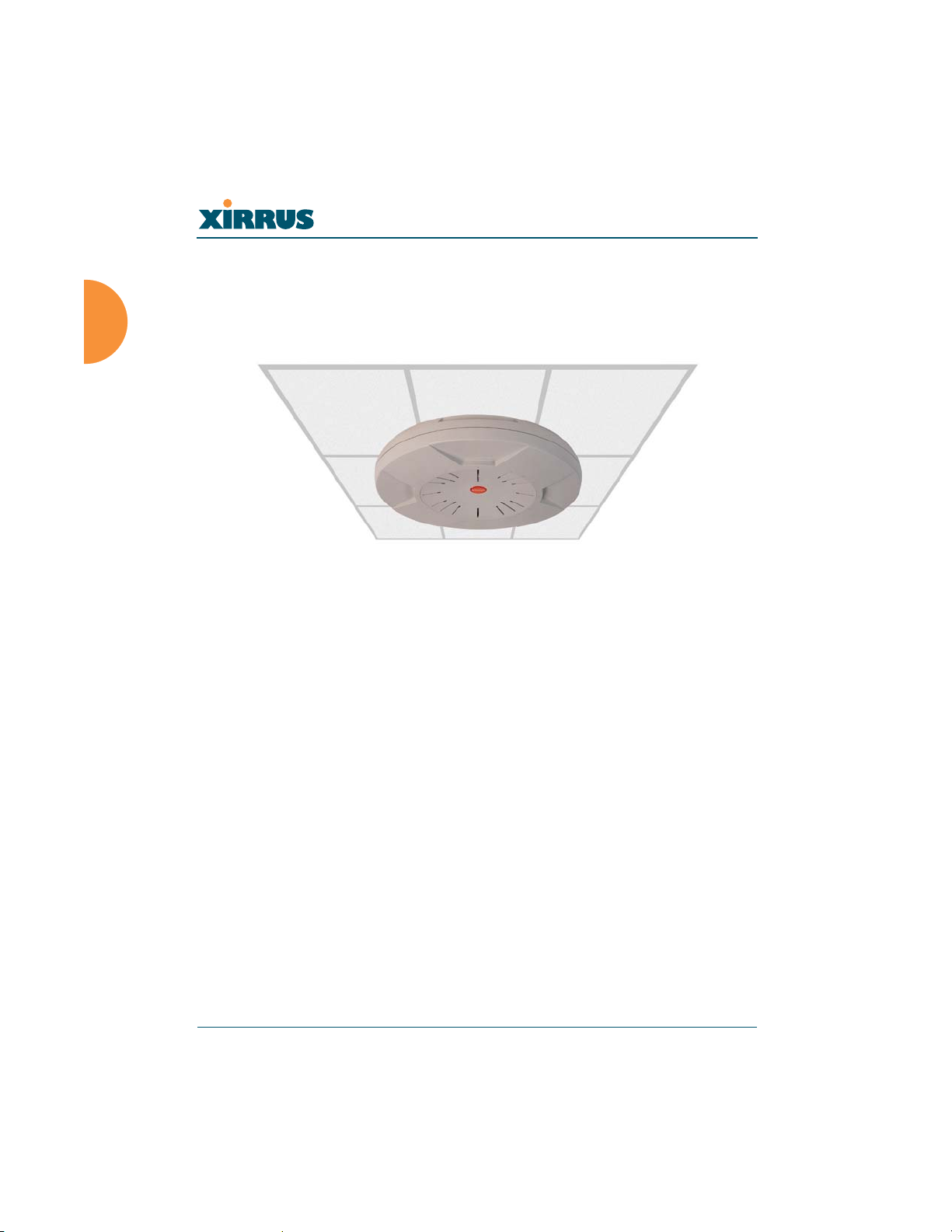
Wireless LAN Array
Product Overview
Part of the family of Xirrus products, the Wireless LAN Array is a high capacity,
multi-mode device designed for the Enterprise market, with twice the range and
up to sixteen times the capacity of competitive wireless products.
Figure 2. Wireless LAN Array (XS-3900)
The Xirrus Array (regardless of the product model) is Wi-Fi® compliant and
simultaneously supports 802.11a, 802.11b and 802.11g clients. Enterprise class
features such as VLAN support and multiple SSID capability enable robust
network compatibility and a high level of scalability and system control. The
optional Xirrus Wireless Management System (XM-3300) allows global
management of hundreds of Arrays from a central location.
The XS-3700 and XS-3500 versions of the Wireless LAN Array deliver a
correspondingly lower capacity than the XS-3900.
Enterprise Class Security
The latest and most effective wireless encryption security standards, including
WPA (Wi-Fi Protected Access) with 802.11i AES (Advanced Encryption Standard)
are provided with the Xirrus Array. In addition, the use of an embedded RADIUS
server (or 802.1x with an external RADIUS server) ensures user authentication—
multiple Arrays can authenticate to the optional XM-3300 ensuring only
authorized Xirrus Wireless LAN Arrays become part of the wireless network.
Rogue AP detection and site monitoring is performed in the background by the
Array automatically.
6 Introduction
Page 42

Wireless LAN Array
Deployment Flexibility
Xirrus’ unique multi-radio architecture generates 360 degrees of sectored highgain 802.11a/b/g coverage that provides extended range and the highest possible
data rates for a large volume of clients. Each sector can be controlled
automatically or manually, creating a pattern of wireless coverage perfectly
tailored to individual customer needs. For example:
outside wall
Figure 3. Wireless Coverage Patterns
Figure 2 depicts the following two scenarios:
z Full pattern coverage
All radios are activated with coverage spanning 360 degrees. If within
range, clients will always receive coverage regardless of their geographic
position relative to the Array.
z Partial pattern coverage
If desired, the Xirrus Array can be deployed close to an exterior wall. In
this case, half of all available radios have been deactivated to prevent
redundant signals from “bleeding” beyond the site’s perimeter wall. This
configuration may also be used in those cases where you want to restrict
wireless coverage to selected areas of the building’s interior.
Introduction 7
Page 43
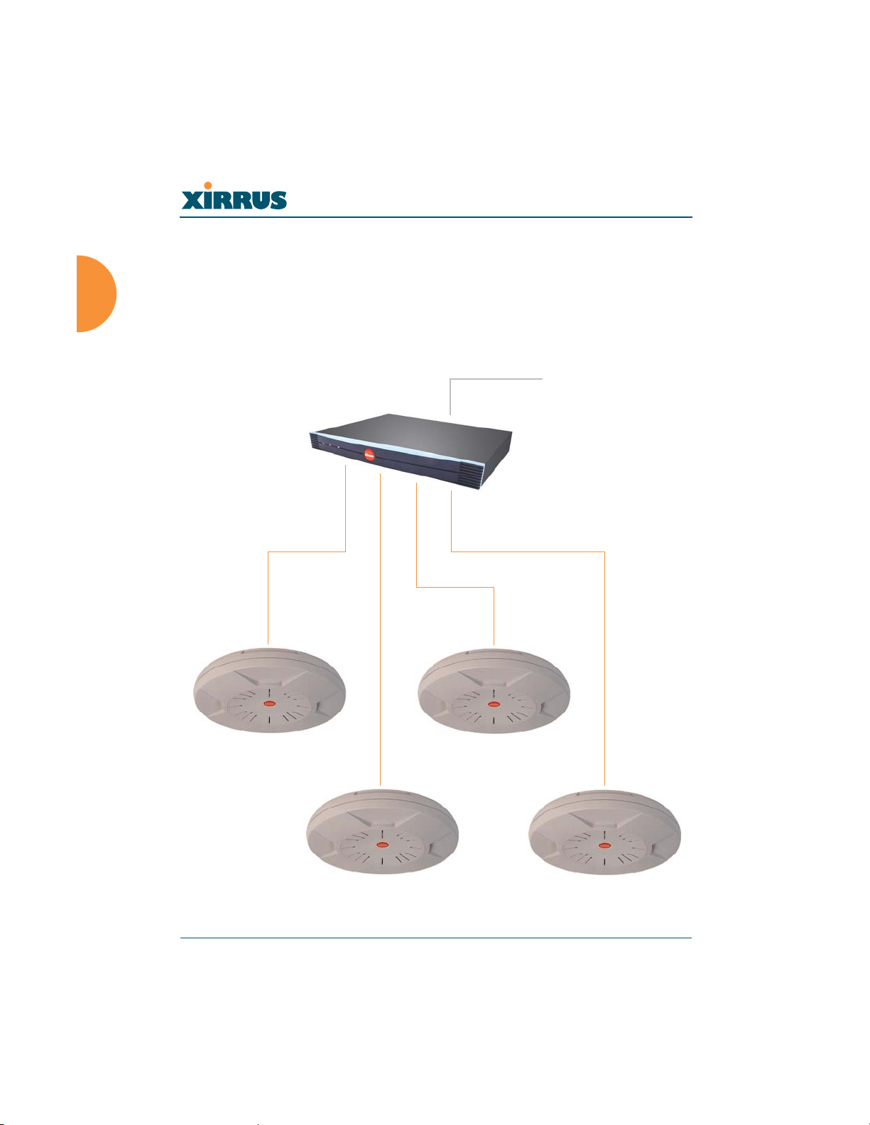
Wireless LAN Array
Remote DC Power System (Optional)
The Xirrus Remote DC Power System (XP-3100) provides distributed DC power
to your Array (DC version) deployments, eliminating the need to provide an AC
power outlet in close proximity to the unit(s).
In the following example, DC power is supplied to four Xirrus Arrays while
utilizing only one AC power outlet.
AC Input to XP-3100
XP-3100
DC Output to Xirrus Arrays
Figure 4. Remote DC Power Distribution
8 Introduction
Page 44
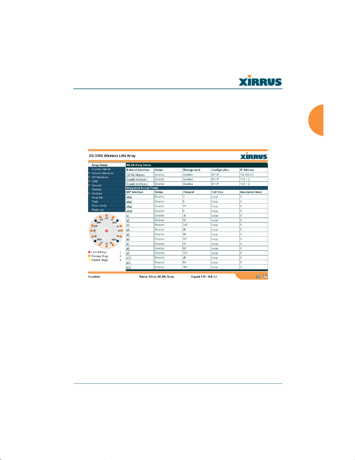
Wireless LAN Array
Enterprise Class Management
The Xirrus Array can be configured with its default RF settings, or the RF settings
can be customized using the Array’s embedded Web Management Interface
(WMI). The WMI enables easy configuration and control from a graphical
console, along with a full compliment of troubleshooting tools, reports and
statistics.
Figure 5. WMI: Array Status Page
In addition, a fully featured Command Line Interface (CLI) offers IT professionals
a familiar management and control environment. SNMP (Simple Network
Management Protocol) is also supported to allow management from an SNMP
compliant management tool, such as the optional Xirrus Wireless Management
System.
#
Introduction 9
For deployments of more than two Arrays, we recommend that you use the
Xirrus Wireless Management System (XM-3300). The XM-3300 offers a rich
set of features for fine control over large deployments.
Page 45

Wireless LAN Array
Key Features and Benefits
This section describes some of the key product features and the benefits you can
expect when deploying the Xirrus Array (the XS-3900 product is highlighted in
this section).
High Capacity and High Performance
The XS-3900 easily handles time-sensitive traffic, such as voice, and can enable
wireless connectivity for 1,024 users. The unit includes two Gigabit uplink ports
for connection to the wired network. A total of sixteen IAPs provides a maximum
wireless capacity of 864 Mbps, which offers ample reserves for the high demands
of current and future applications. Of the sixteen IAPs, twelve operate in the
802.11a mode and four operate in any combination of 802.11a, 802.11b and
802.11g.
If desired, IAP (radio) abg2 can also be configured in RF monitoring and rogue
AP detection mode.
a12
a11
abg4
a1
abg1
a10
a9
a8
abg3
a7
a6
Mode(s) IAP number
Figure 6. Layout of IAPs (XS-3900)
10 Introduction
a2
a3
a4
abg2 (RF monitoring)
a5
Page 46
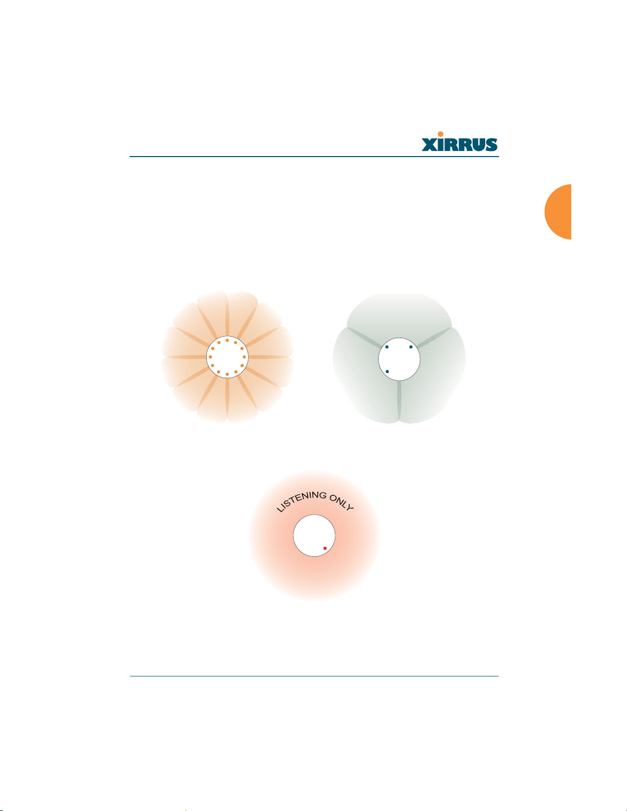
Wireless LAN Array
Extended Coverage
One XS-3900 solution enables you to replace up to sixteen access points (includes
one omnidirectional IAP for monitoring the network). Fifteen IAP radios with
integrated directional antennas provide increased wireless range and enhanced
data rates in all directions. With a Xirrus Array deployed, far fewer access points
are needed for your wireless network. Radio abg2 (see Figure 6) can be switched
to use an integrated omnidirectional antenna—for listening only—and can be
dedicated to the tasks of site monitoring and rogue AP detection.
Array
Array
802.11a (directional) 802.11a/b/g (directional)
Array
802.11a/b/g (omnidirectional)
Figure 7. Antenna Patterns
Introduction 11
Page 47

Wireless LAN Array
Non-Overlapping Channels
Complete use of non-overlapping channels limits interference and delivers
maximum capacity. On the XS-3900, all 16 non-overlapping channels are fully
utilized across the 5GHz and 2.4GHz spectrums (up to 12 across the 5GHz
spectrum and up to 3 across the 2.4GHz spectrum—typically, one radio is used as
a dedicated RF monitor).
Secure Wireless Access
Multiple layers of authentication and encryption ensure secure data
transmissions. The Xirrus Array is 802.11i compliant with encryption support for
64 bit and 128 bit WEP, and WPA with TKIP and AES encryption.
Authentication support is provided via 802.1x, including PEAP, EAP-TLS, and
EAP-TTLS.
Applications Enablement
QoS (Quality of Service) functionality combined with true switch capabilities
enable high density Voice over Wireless LAN deployments. Compliant with
802.1p and 802.1q standards.
SDMA Optimization
SDMA (Spatial Division Multiple Access) technology provides full 360° coverage
while allowing independent channel and power output customization. Also
supports fast inter-zone handoffs for time-sensitive applications and roaming
support.
Easy Deployment
The Xirrus Wireless Management System (XM-3300) offers real time monitoring
and management capabilities of the wireless network—ideal for the Enterprise
market. It also allows you to import floor plans to help you plan your
deployment. The Xirrus Wireless LAN Array chassis has a plenum rated, lockable
and tamper resistant case.
12 Introduction
Page 48
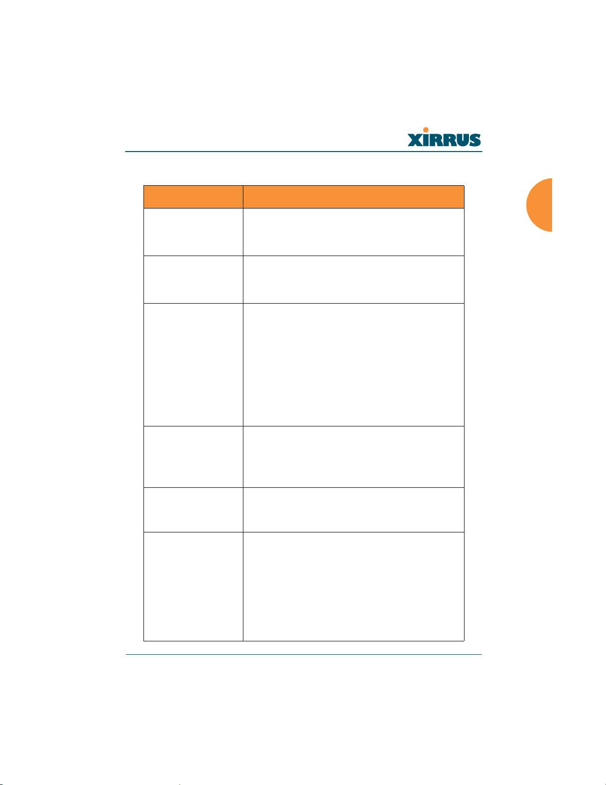
Wireless LAN Array
Product Specifications (XS-3900 and XS-3700)
Element Specifications
Number of Users Maximum of 64 associated users per radio
1024 users per Array (XS-3900)
512 users per Array (XS-3700)
Physical Diameter: 18.65 inches (47.37 cm)
Height: 3.87 inches (9.83 cm)
Weight: 8lbs (3.63 kg)
Environmental Operating Temperature:
-10°C to 50°C
0% to 90% relative humidity (non-condensing)
Storage Temperature:
-20°C to 60°C
5% to 95% relative humidity (non-condensing)
Maximum Operating Altitude:
2000 meters (6561 feet)
System 825 MHz CPU
128MB RAM, expandable
512MB system flash, expandable
Expansion slot for future options
Electrical Input Power (AC version): 90VAC to 265VAC
at 47Hz to 63Hz
Input Power (DC version): 48VDC
Interfaces Serial:
1 x RS232 – RJ45 connector
Ethernet Interfaces:
2 x Gigabit 10/100/1000 Mbps w/failover
1 x Fast Ethernet 10/100 Mbps
Status LEDs:
System status, Ethernet, Radio
Introduction 13
Page 49
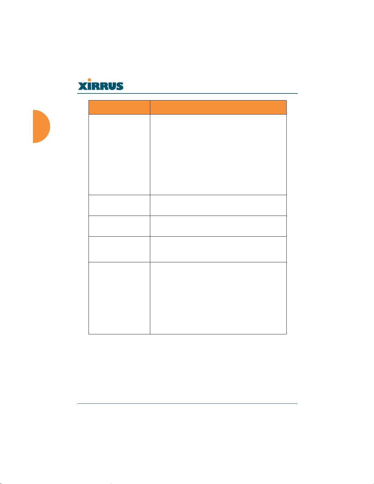
Wireless LAN Array
Element Specifications
Management Web-based HTTPS
SNMP v3
CLI via SSHv2 or Telnet
FTP
TFTP
Serial
Proprietary
Xirrus Wireless Management System
Syslog reporting for alerts/alarms
Networking DHCP client, DHCP server, NTP client
RFC
VLAN Support 802.1Q, P VLAN
Supports up to 16 VLANs
Multiple SSID
Support
Allows up to 16 separate SSIDs to be defined
with map security, VLAN and QoS settings for
each SSID
Performance Client Load Balancing
Automatic load balancing between system
radios
Quality of Service:
802.1P wired traffic prioritization
Wireless packet prioritization
MAP CoS to TCID
Fair queuing of downstream traffic
14 Introduction
Page 50

Wireless LAN Array
Element Specifications
Security Wireless Security:
WEP 40bit/128bit encryption
WPA with TKIP and AES encryption
Misappropriated APs automatically reset to
factory defaults (requires the Xirrus Wireless
Management System)
Rogue AP detection, with alerts and
classification
User and System Authentication:
WPA Pre-Shared Key authentication
Embedded RADIUS Server
802.1x EAP-TLS
802.1x EAP-TTLS
802.1x PEAP
External RADIUS servers
Authentication of Xirrus Arrays to the Xirrus
Management System (XM-3300)
Introduction 15
Page 51

Element Specifications
Wireless Number of Radios:
XS-3900: 12 x 802.11a radios
4 x 802.11a/b/g radios
XS-3700: 4 x 802.11a radios
4 x 802.11a/b/g radios
Wireless Standards:
802.11a/b/g and g-only mode
802.11e (draft), 802.11i
Channel Selection:
Manual
Automatic
Frequency Bands:
11a: 5.15-5.25 GHz (UNII 1)
11a: 5.15-5.25 GHz (TELEC)
11a: 5.25-5.35 GHz (UNII 2)
11a: 5.470-5.725 (ETSI)
11a: 5.725-5825 GHz (UNII 3)
11b/g: 2.412-2.462 GHz (FCC)
11b/g: 2.412-2.472 GHz (ETSI)
11b/g: 2.412-2.484 GHz (TELEC)
Wireless LAN Array
Antenna:
Internal 6 dBi sectorized antenna
External RP-TNC connector
Radio Approvals:
FCC (United States)
EN 301.893 (Europe)
Compliance UL / cUL 60950 and EN 60950
FCC Part 15.107 and 15109, Class A
EN 301.489 (Europe)
Warranty One year (hardware), 90 day (software)
16 Introduction
Page 52
Wireless LAN Array
Product Specifications (XS-3500)
Element Specifications
Number of Users Maximum of 64 associated users per radio (256
users per Array). Recommended number of
typical users per Array is 20.
Physical Diameter: 12.58 inches (31.95 cm)
Height: 2.58 inches (6.55 cm)
Weight: 4lbs (1.81 kg)
Environmental Operating Temperature:
-10°C to 50°C
0% to 90% relative humidity (non-condensing)
Storage Temperature:
-20°C to 60°C
5% to 95% relative humidity (non-condensing)
Maximum Operating Altitude:
2000 meters (6561 feet)
System 825 MHz CPU
128MB RAM, expandable
512MB system flash, expandable
Expansion slot for future options
Electrical Input Power (AC version): 90VAC to 265VAC
at 47Hz to 63Hz
Input Power (DC version): 48VDC
Interfaces Serial:
1 x RS232 – RJ45 connector
Ethernet Interfaces:
1 x Gigabit 10/100/1000 Mbps w/failover
Status LEDs:
System status, Ethernet, Radio
Introduction 17
Page 53
Wireless LAN Array
Element Specifications
Management Web-based HTTPS
SNMP v3
CLI via SSHv2 or Telnet
FTP
TFTP
Serial
Proprietary
Xirrus Wireless Management System
Syslog reporting for alerts/alarms
Networking DHCP client, DHCP server, NTP client
RFC
VLAN Support 802.1Q, P VLAN
Supports up to 16 VLANs
Multiple SSID
Support
Allows up to 16 separate SSIDs to be defined
with map security, VLAN and QoS settings for
each SSID
Performance Client Load Balancing
Automatic load balancing between system
radios
Quality of Service:
802.1P wired traffic prioritization
Wireless packet prioritization
MAP CoS to TCID
Fair queuing of downstream traffic
18 Introduction
Page 54

Wireless LAN Array
Element Specifications
Security Wireless Security:
WEP 40bit/128bit encryption
WPA with TKIP and AES encryption
Misappropriated APs automatically reset to
factory defaults (requires the Xirrus Wireless
Management System)
Rogue AP detection, with alerts and
classification
User and System Authentication:
WPA Pre-Shared Key authentication
Embedded RADIUS Server
802.1x EAP-TLS
802.1x EAP-TTLS
802.1x PEAP
External RADIUS servers
Authentication of Xirrus Arrays to the Xirrus
Management System (XM-3300)
Introduction 19
Page 55

Element Specifications
Wireless Number of Radios:
4 x 802.11a/b/g radios
Wireless Standards:
802.11a/b/g and g-only mode
802.11e (draft), 802.11i
Channel Selection:
Manual
Automatic
Frequency Bands:
11a: 5.15-5.25 GHz (UNII 1)
11a: 5.15-5.25 GHz (TELEC)
11a: 5.25-5.35 GHz (UNII 2)
11a: 5.470-5.725 (ETSI)
11a: 5.725-5825 GHz (UNII 3)
11b/g: 2.412-2.462 GHz (FCC)
11b/g: 2.412-2.472 GHz (ETSI)
11b/g: 2.412-2.484 GHz (TELEC)
Antenna:
4 internal 3 dBi 180° 802.11b/g sectorized
antennas
1 internal 2 dBi 360° omni-directional antenna
External RP-TNC connector
Radio Approvals:
FCC (United States)
EN 301.893 (Europe)
Wireless LAN Array
Compliance UL / cUL 60950 and EN 60950
FCC Part 15.107 and 15109, Class A
EN 301.489 (Europe)
Warranty One year (hardware), 90 day (software)
20 Introduction
Page 56

Wireless LAN Array
Installing the Xirrus Array
This chapter defines the prerequisites for installing the Xirrus Array and provides
instructions to help you complete a successful installation. Section headings for
this chapter include:
z “Installation Prerequisites” on page 21
z “Planning Your Installation” on page 24
z “Installation Workflow” on page 39
z “Unpacking the Xirrus Array” on page 40
z “Installing Your Xirrus Wireless LAN Array” on page 41
z “Powering Up the Xirrus Wireless LAN Array” on page 51
z “Establishing Communication with the Array” on page 53
z “Performing the Express Setup Procedure” on page 54
Installation Prerequisites
Your Xirrus Array deployment requires the presence of hardware and services in
the host wired/wireless network, including:
z Dedicated AC power outlet
Unless you are using the Xirrus Remote DC Power System (XP-3100) with
the DC version of the Xirrus Array, you need a dedicated power outlet to
supply AC power to each unit deployed at the site. If you are using the
optional XP-3100, then DC power is supplied to all units and only one AC
outlet is required for the XP-3100.
z Ethernet port (read notes)
You need at least one 10/100/1000 BaseT port to establish wired Gigabit
Ethernet connectivity (via the product’s Gigabit 1 or Gigabit 2 port) and
one 10/100 BaseT port (if desired) for product management.
The Array’s Ethernet ports should be plugged into an Ethernet switch, not
!
an Ethernet hub—if a hub is used, we recommend that you connect only
one Ethernet port.
Installing the Xirrus Array 21
Page 57
Wireless LAN Array
The Gigabit1 Ethernet interface is the primary port for both data and
!
management traffic. If a single Ethernet connection is used, it must be
connected to the Gigabit1 Ethernet interface.
The 10/100 Ethernet Port can be used for managing the Array, and will
only bridge management traffic. See also, “Port Failover Protection” on
page 33.
z Secure Shell (SSH) utility
To establish secure remote command line access to the Array, you need a
Secure Shell (SSH) utility, such as PuTTY.
z Secure Web browser
Either Internet Explorer (version 6.0 or higher), Netscape Navigator
(version 7.0 or higher), or Mozilla Firefox (version 1.01 or higher) and it
must be available on the same subnet as the Array. A secure Web browser
is required for Web-based management of the Array.
z Serial connection capability
To connect directly to the console port on the Array, your computer must
be equipped with a male 9-pin serial port and terminal emulation
software (for example, HyperTerminal).
Use the following settings when establishing a serial connection:
Bits per second 115,200
Data bits 8
Parity None
Stop bits 1
Flow control None
22 Installing the Xirrus Array
Page 58

Wireless LAN Array
Optional Network Components
The following network components are optional.
z DHCP server
To distribute IP addresses and ancillary information to your Xirrus Array.
z Xirrus Wireless Management System (XM-3300)
The optional XM-3300 offers powerful management features for small or
large Xirrus Array deployments.
z Xirrus Remote DC Power System (XP-3100)
The optional XP-3100 provides distributed DC power to multiple Arrays,
eliminating the need to run dedicated AC power to each unit and
facilitating backup power when connected via a UPS.
z External RADIUS server
Although your Array comes with an embedded RADIUS server, for
802.1x authentication in large deployments you may want to add an
external RADIUS server.
Client Requirements
The Xirrus Array should only be used with Wi-Fi certified client devices.
Installing the Xirrus Array 23
Page 59

Wireless LAN Array
Planning Your Installation
This section provides guidelines and examples to help you plan your Xirrus
Array deployment to achieve the best overall coverage and performance. We
recommend you conduct a site survey to determine the best location and settings
for each Array you install.
General Deployment Considerations
The Xirrus Array’s unique multi-radio architecture generates 360 degrees of
sectored high-gain 802.11a/b/g coverage that provides extended range. However,
the number, thickness and location of walls, ceilings or other objects that the
wireless signals must pass through may affect the range. Typical ranges vary
depending on the types of materials and background RF (radio frequency) noise
at your location. To maximize wireless range, follow these basic guidelines:
1. Keep the number of walls and ceilings between the Array and your
receiving devices to a minimum—each wall or ceiling can reduce the
wireless range from between 3 and 90 feet (1 to 30 meters). Position your
devices so that the number of walls or ceilings is minimized.
2. Be aware of the direct line between each device. For example, a wall that
is 1.5 feet thick (half a meter) at 90° is actually almost 3 feet thick (or 1
meter) when viewed at a 45° angle. At an acute 2° degree angle the same
wall is over 42 feet (or 14 meters) thick! For best reception, try to ensure
that your wireless devices are positioned so that signals will travel
straight through a wall or ceiling.
90° 45°
< 3 feet
1.5 feet
Figure 8. Wall Thickness Considerations
24 Installing the Xirrus Array
2°
> 42 feet
Page 60
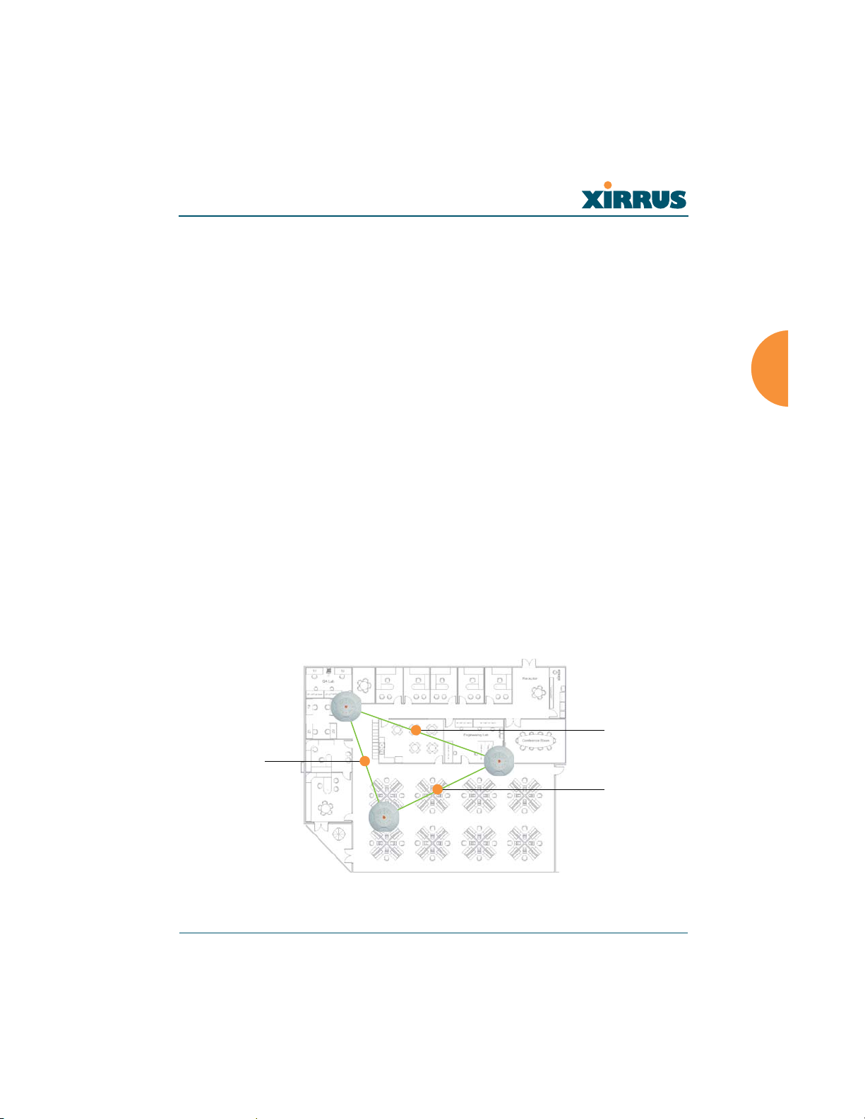
Wireless LAN Array
3. Building materials can make all the difference. For example, solid metal
doors or aluminum wall studs may adversely effect wireless signals. Try
to position wireless client devices so that the signal passes through
drywall (between studs) or open doorways and not other materials.
Coverage and Capacity Planning
This section considers coverage and capacity for your deployment(s), including
placement options, RF patterns and cell sizes, area calculations, roaming
considerations, and channel allocations.
Placement
Use the following guidelines when considering placement options:
1. The best placement option for the Array is ceiling-mounted within an
open plan environment (cubicles rather than fixed walls).
2. Keep the Array away from electrical devices or appliances that generate
RF noise. Because the Array is generally mounted on ceilings, be aware of
its position relative to lighting (especially fluorescent lighting)—we
recommend maintaining a distance of at least 3 to 6 feet (or 1 to 2 meters).
3. If using multiple Arrays at the same location, we recommend
maintaining a distance of at least 100 feet between units.
t100 ft
t100 ft
t100 ft
Figure 9. Unit Placement
Installing the Xirrus Array 25
Page 61
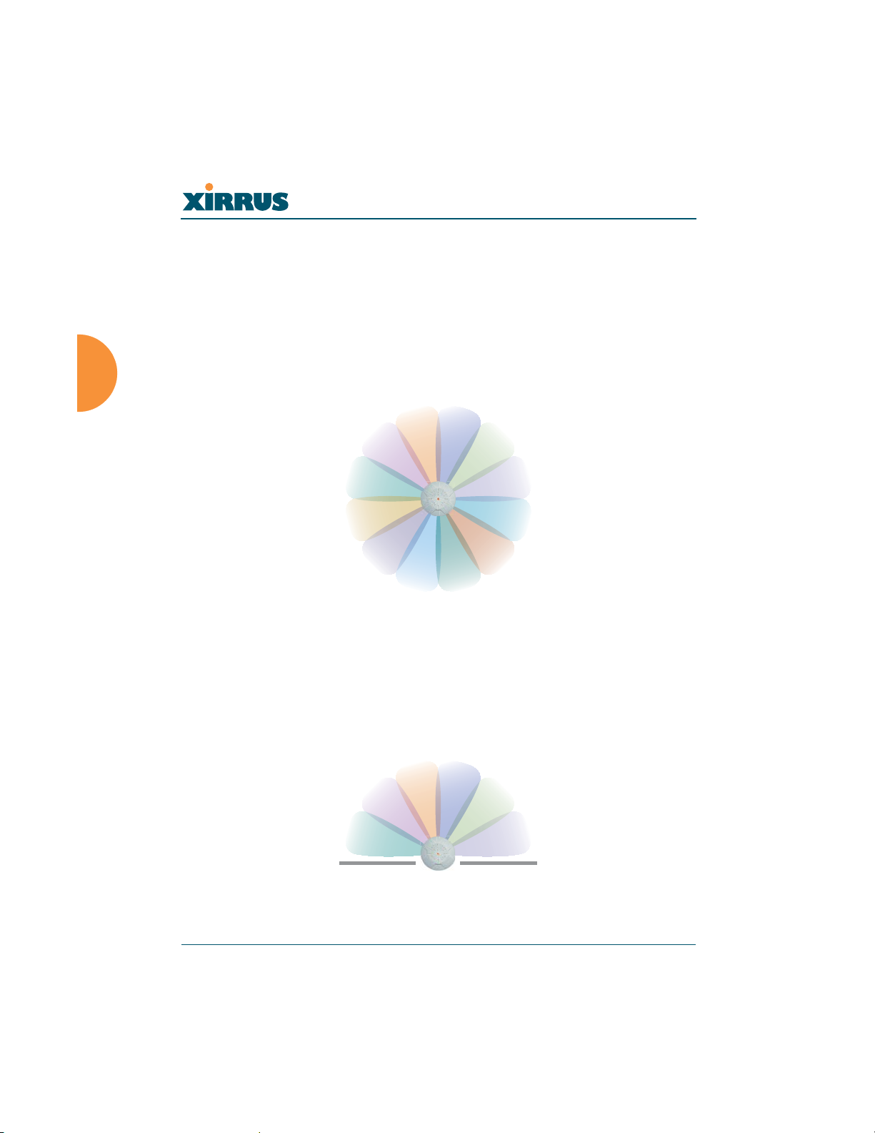
Wireless LAN Array
RF Patterns
The Xirrus Array allows you to control—automatically or manually—the pattern
of wireless coverage that best suits your deployment needs. You can choose to
operate with full coverage, half coverage, or custom coverage (by enabling or
disabling individual sectors).
Full (Normal) Coverage
In normal operation, the Array provides a full 360 degrees of coverage.
Figure 10. Full (Normal) Coverage
Half Coverage
If installing a unit close to an exterior wall, you can deactivate half of the radios to
prevent redundant signals from “bleeding” beyond the wall and extending
service into public areas. The same principle applies if you want to restrict service
to an adjacent room within the site.
outside wall
Figure 11. Adjusting RF Patterns
26 Installing the Xirrus Array
Page 62

Wireless LAN Array
Custom Coverage
Where there are highly reflective objects in close proximity to the Array, you can
turn off specific radios to avoid interference and feedback.
reflective
object
Figure 12. Custom Coverage
Calculating Areas
Before we discuss cell sizes, it is useful to know how to calculate the area of a
circle (because the Array radiates a full 360 degrees). The area of a circle is equal
to pi (
S) times the square of the radius, where pi is equal to 3.14. The following
graphic calculates the area of a circle with a radius of 20 feet.
3.14 x 202 = 1,256 sq ft
20 ft
Figure 13. Calculating the Area of a Circle
Installing the Xirrus Array 27
Page 63
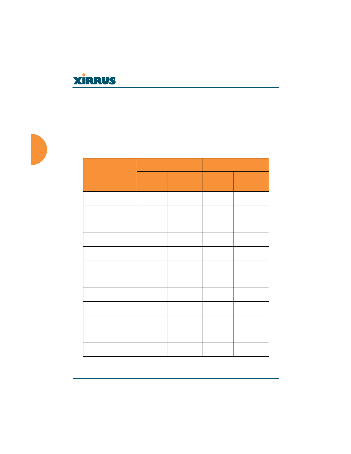
Wireless LAN Array
Capacity and Cell Sizes
Cell sizes should be calculated based on the number of users, the applications
being used (for example, data/video/voice), and the number of Arrays available
at the location. The capacity of a cell is defined as the minimum data rate desired
for each sector multiplied by the total number of sectors being used.
The following chart shows the maximum recommended cell sizes for each data
rate.
Desired
Data Rate
(Mbps)
11a Cell Size 11b/g Cell Size
Radius
(feet)
Area
(sq. feet)
Radius
(feet)
54 100 31,400 104 33,962
48 185 107,466 183 105,155
36 247 191,568 260 212,264
24 278 242,672 283 251,479
18 309 299,810 338 358,726
12 339 360,852 364 416,037
9 371 432,193 374 439,211
6 402 507,437 390 477,594
11 0 0 416 543,396
5.5 0 0 437 649,295
Area
(sq. feet)
2 0 0 458 658,659
1 0 0 468 687,735
28 Installing the Xirrus Array
Page 64

Wireless LAN Array
Sample 802.11a Cells
The following 802.11a sample cells illustrate the coverage area and minimum
throughput you can expect (per sector) based on the size of each cell. Notice how
the throughput increases as the cell size decreases, and vice versa.
68 ft
14,520 sq ft
54 Mbps per sector
98 ft
30,157 sq ft
36 Mbps per sector
165 ft
85,487 sq ft
18 Mbps per sector
Figure 14. Sample 802.11a Cells
Installing the Xirrus Array 29
Page 65

Wireless LAN Array
Fine Tuning Cell Sizes
Adjusting the transmit power allows you to fine tune cell sizes. There are three
settings—Large, Medium, or Small (the default is Large). If you are installing
many units in close proximity to each other, reduce the transmit power to avoid
excessive interference with other Arrays or installed APs. See also, “IAP Settings”
on page 90.
Small
Medium
Large
Figure 15. Transmit Power
Roaming Considerations
Cells should overlap approximately 10 - 15% to accommodate client roaming.
ROAMING
10 - 15% overlap
Figure 16. Overlapping Cells
30 Installing the Xirrus Array
Page 66

Wireless LAN Array
Allocating Channels
Because the Xirrus Array is a multi-channel device, allocating the best channels to
radios is important if peak performance is to be maintained.
Automatic Channel Selection
We recommend that you allow the Array to make intelligent channel allocation
decisions automatically. In the automatic mode, channels are allocated
dynamically, driven by changes in the environment.
Manual Channel Selection
You can manually assign channels on a per radio basis, though manual selection
is not recommended (and not necessary).
#
To avoid co-channel interference, do not select adjacent channels for radios that
are physically next to each other.
Maintain channel separation
Figure 17. Allocating Channels Manually
Installing the Xirrus Array 31
Page 67

Wireless LAN Array
Deployment Examples
The following examples employ 802.11a cells, each offering minimum
throughputs of 54 Mbps, 36 Mbps, and 18 Mbps per sector respectively, and
assume a floor plan covering a total area of about 60,000 square feet.
Figure 18. Deployment Scenario (54 Mbps)—Per Sector
Figure 19. Deployment Scenario (36 Mbps)—Per Sector
32 Installing the Xirrus Array
Page 68
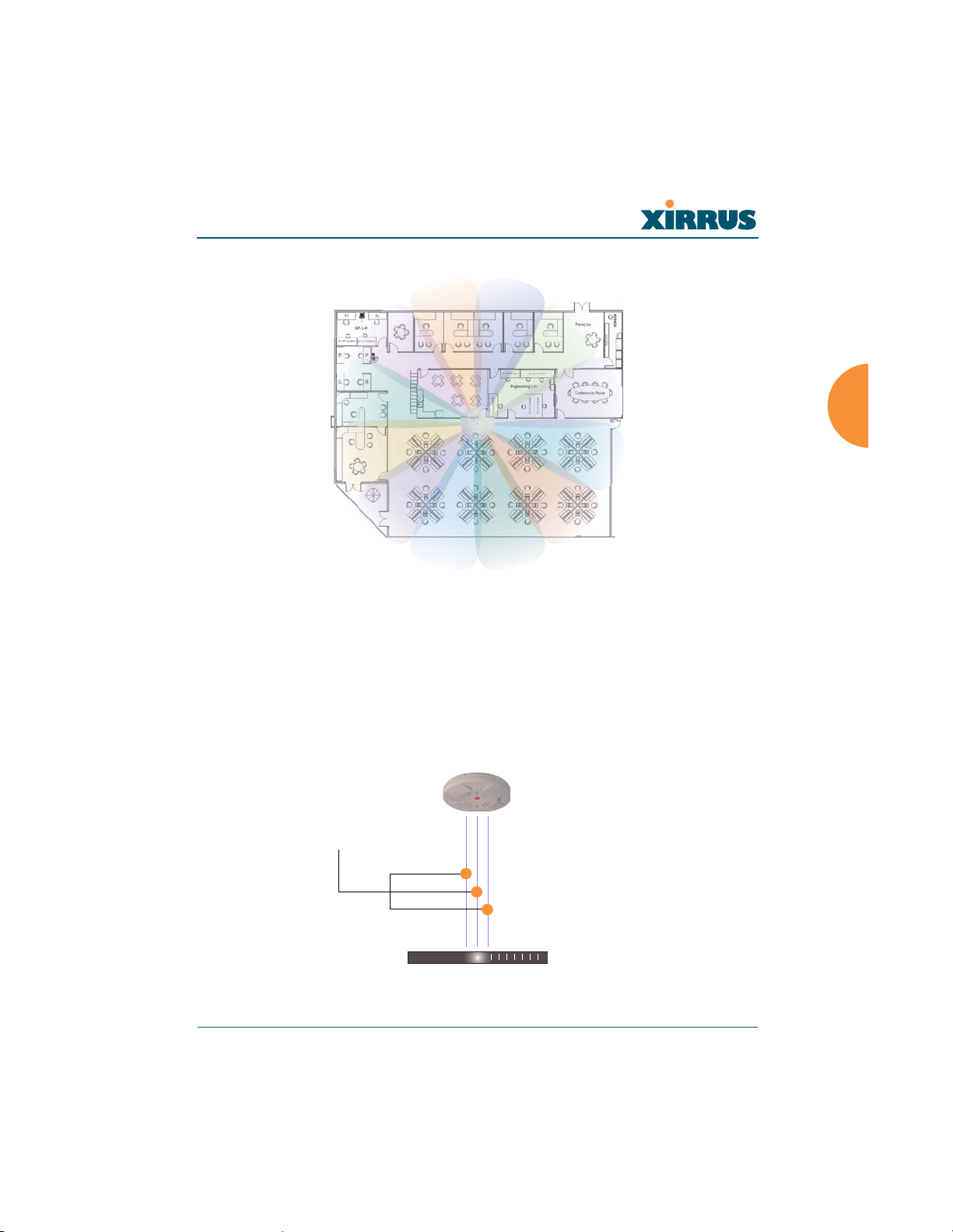
Wireless LAN Array
Figure 20. Deployment Scenario (18 Mbps)—Per Sector
Failover Planning
This section discusses failover protection at the unit and port levels.
Port Failover Protection
To ensure that service is continued in the event of a port failure, you can utilize
the Gigabit 1 and Gigabit 2 ports simultaneously.
Multiple port connections
Ethernet switch
Figure 21. Port Failover Protection
Installing the Xirrus Array 33
Page 69
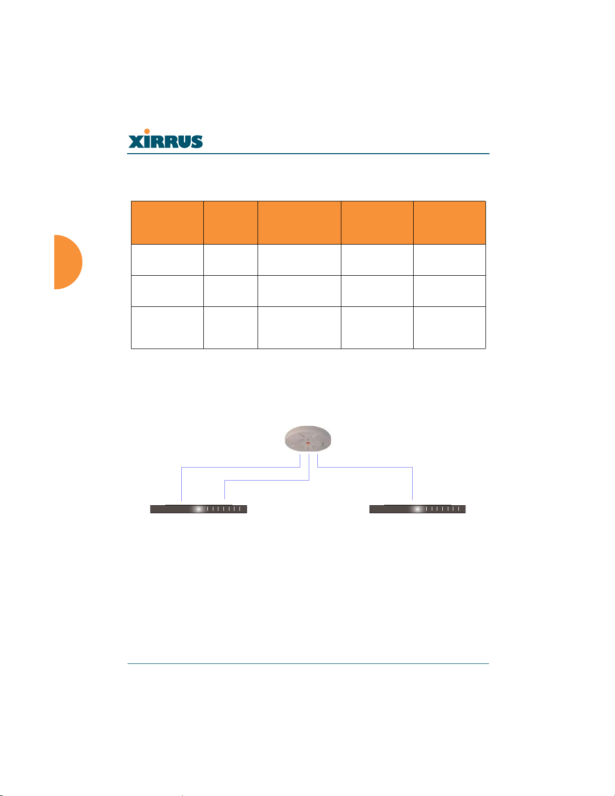
Wireless LAN Array
In addition, the Array has full failover protection between the Gigabit 1 and
Gigabit 2 Ethernet ports (see following table).
Interface
Fast Ethernet No Yes None DHCP or
Gigabit 1 Yes Yes Gigabit 2 DHCP or
Gigabit 2 Yes Yes Gigabit 1 Assumes the
Switch Failover Protection
To ensure that service is continued in the event of a switch failure, you can
connect Arrays to more than one Ethernet switch (not a hub).
Bridges
Data?
Ethernet connections
Bridges
Management
Traffic?
Fails Over To: IP address
static
static
IP address of
Gigabit 1
Ethernet switch
Figure 22. Switch Failover Protection
#
34 Installing the Xirrus Array
Gigabit Ethernet connections must be on the same subnet.
Backup switch
Page 70

Wireless LAN Array
Power Planning
This section discusses the AC and DC power options.
AC Power
The AC power option requires a direct connection between the Array and a
dedicated AC power outlet. The power cord is provided with the unit.
Remote Distributed DC Power
To deliver DC power to the Array, you must have the optional Xirrus Remote DC
Power System (XP-3100) and a Xirrus Array that supports DC power—see
Figure 4 on page 8 . The XP-3100 provides DC power to multiple Arrays from a
single source, and requires only one AC power outlet.
Depending on the type of cable used, Arrays can be located up to 1,000 feet from
the XP-3100. In addition, the XP-3100 can be plugged into a UPS to prevent power
failure to all Arrays in the network.
#
When using CAT5 cable, DC power can be provided up to a distance of 300
feet.
Security Planning
This section offers some useful guidelines for defining your preferred encryption
and authentication method. For additional information, go to the Security section
of “Frequently Asked Questions” on page 222.
Wireless Encryption
Encryption ensures that no user can decipher another user’s data transmitted
over the airwaves. There are three encryption options available to you, including:
z WEP-40bit or WEP-128bit
Because WEP is vulnerable to cracks, we recommend that you only use
this for legacy devices that cannot support a stronger encryption type.
z Wi-Fi Protected Access
This is much more secure than WEP and uses TKIP for encryption.
Installing the Xirrus Array 35
Page 71

Wireless LAN Array
z Wi-Fi Protected Access with AES
This is government-grade encryption—available on most new client
adapters—and uses the AES–CCM encryption mode (Advanced
Encryption Standard–Counter Mode).
Authentication
Authentication ensures users are who they say they are, and occurs when users
attempt to join the wireless network and periodically there after. The following
authentication methods are available with the XS-3900:
z RADIUS 802.1x
802.1x uses a remote RADIUS server to authenticate large numbers of
clients, and can handle different authentication methods (EAP-TLS, EAPTTLS EAP-PEAP).
z Xirrus internal RADIUS server
Includes all the core functionality of a full RADIUS server built into the
Xirrus Array. Recommended for smaller numbers of users (about 100 or
less).
z Pre-Shared Key
Uses a pass-phrase or key that is manually distributed to all authorized
users. The same passphrase is given to client devices and entered into
each Array.
z MAC Access Control Lists (ACLs)
MAC access control lists provide a list of client adapter MAC addresses
that are allowed or denied access to the wireless network, and can be
used in addition to any of the above authentication methods. ACLs are
good for embedded devices, like printers and bar-code scanners (though
MAC addresses can be spoofed). The Xirrus Array supports 512 ACL
entries.
36 Installing the Xirrus Array
Page 72

Wireless LAN Array
Network Management Planning
Network management can be performed using any of the following methods:
z Command Line Interface, using an SSH (Secure Shell) utility, like PuTTY.
z Web-based management, using the Array’s embedded Web Management
Interface (WMI). This method provides configuration and basic
monitoring tools, and is good for small deployments (one or two units).
z Web-based management, using the optional Xirrus Wireless Management
System (XM-3300). The XM-3300 is used for managing large Array
deployments from a centralized Web-based interface and offers the
following features:
Layer 3 appliance
Globally manage large numbers of Arrays
Seamless view of the entire wireless network
Easily configure large numbers of Arrays
Rogue AP monitoring
Easily manage system-wide firmware updates
Monitor performance and trends
Aggregation of alerts and alarms
Installing the Xirrus Array 37
Page 73
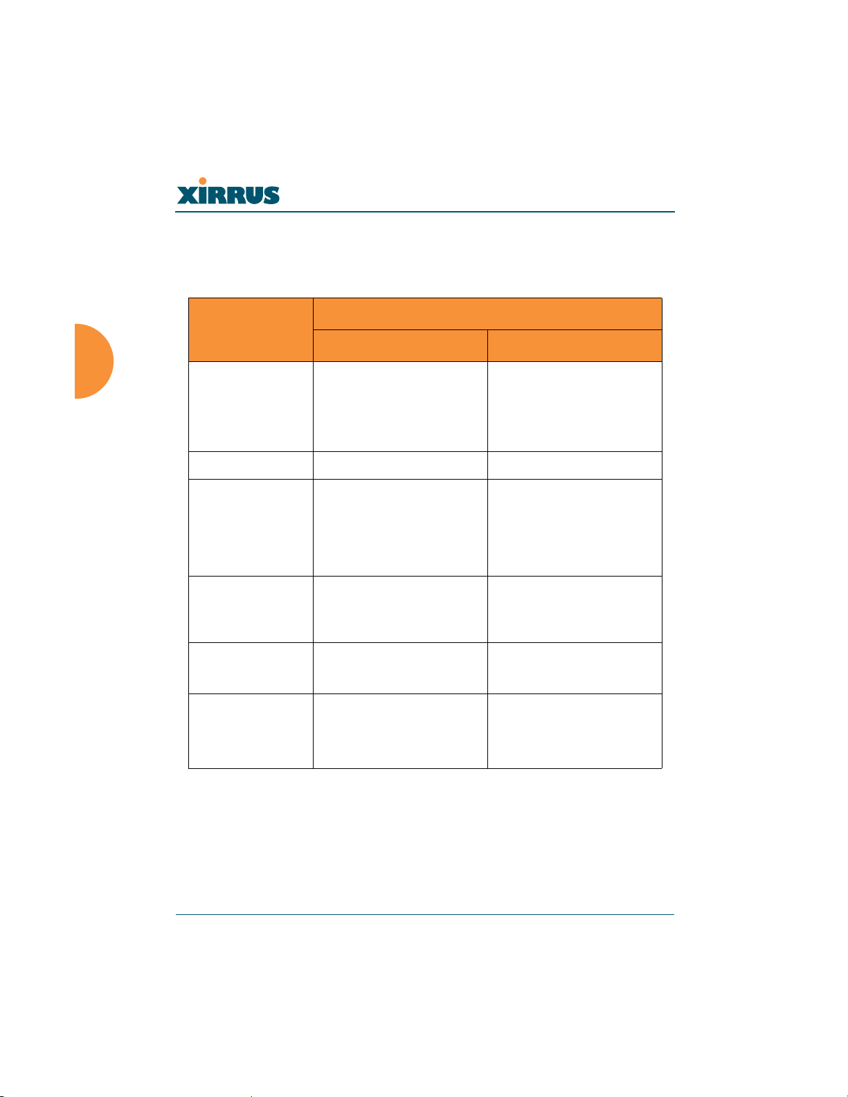
Wireless LAN Array
Deployment Summary
The following table summarizes your deployment options for small and large
deployments.
Number of Xirrus Arrays
Function
One or Two Three or More
Power AC
DC (with XP-3100)
DC (with XP-3100)
AC
UPS backup
(recommended)
Failover Recommended Highly recommended
VLANs Optional Optional use,
Can be used to put all
APs on one VLAN or
map to existing VLAN
scheme
Encryption WPA with TKIP
(recommended)
PSK or 802.1x
Authentication Internal RADIUS server
WPA with AES
(recommended)
802.1x keying
External RADIUS server
Pre-Shared Key
Management Internal WMI
XM-3300
Internal CLI
XM-3300
38 Installing the Xirrus Array
Page 74

Wireless LAN Array
Installation Workflow
This workflow illustrates the steps that are required to install and configure your
Xirrus Array successfully. Review this flowchart before attempting to install the
unit on a customer’s network.
Determine the number of Arrays needed
Choose the location(s) for your Xirrus Arrays
AC DC
Run AC power and Ethernet cables Run DC power and Ethernet cables
Install the mounting plate
Connect the cables and turn on the power
Verify that the Ethernet link and radio LEDs are functioning correctly
Perform the Express Setup procedure
Figure 23. Installation Workflow
AC or DC
power?
Installing the Xirrus Array 39
Page 75
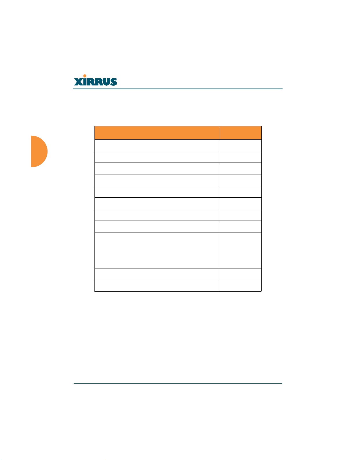
Wireless LAN Array
Unpacking the Xirrus Array
When you unpack your Xirrus Array, you will find the following items in the
carton:
Item Quantity
Xirrus Wireless LAN Array 1
AC power cord 1
Console cable 1
Mounting plate 1
Mounting screws 4
Tile grid mounting clamps 4
Clamp nuts 4
Mounting template 1
CD-ROM containing:
This User’s Guide in PDF format
End User License Agreement (EULA)
README file
Quick Install Guide 1
Registration Card 1
40 Installing the Xirrus Array
1
Page 76
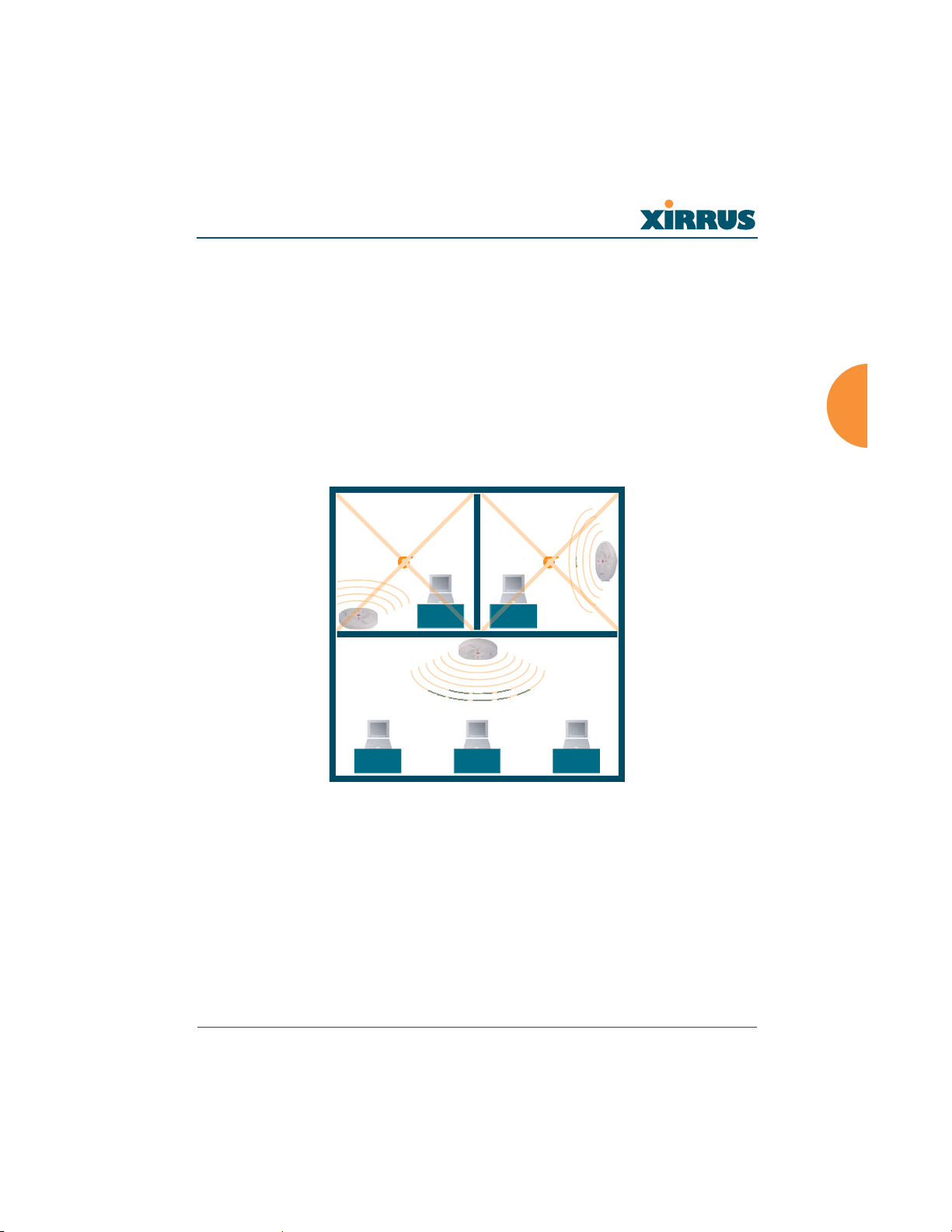
Wireless LAN Array
WR
ONG
CORRECT
WR
G
Installing Your Xirrus Wireless LAN Array
This section provides instructions for installing your Xirrus Wireless LAN Array.
Choosing a Location
Based on coverage, capacity and deployment examples discussed earlier in this
chapter, choose a location for the Array that will provide the best results for your
needs. The Xirrus Array was designed to be mounted on a ceiling where the unit
is unobtrusive and wireless transmissions can travel unimpeded throughout open
plan areas. Choose a location that is central to your users (see the following
diagram for correct placement.
Figure 24. Array Placement
Installing the Xirrus Array 41
Page 77

Wireless LAN Array
Wiring Considerations
Unless you are using the Xirrus Remote DC Power System (XP-3100) with the DC
version of the Array, an AC power outlet must be available to the Array (an AC
power cord is provided with each unit). If you are using the XP-3100 to distribute
DC power to multiple Arrays, go to “Remote DC Power System (Optional)” on
page 8.
Once you have determined the best location for your Xirrus Array, you must run
cables to the location for the following services:
Power
z Dedicated AC power
z DC power (if using the XP-3100)
Network
z Gigabit 1
z Gigabit 2 (optional, not available on the XS-3500)
z Fast Ethernet (optional, not available on the XS-3500)
z Serial cable
42 Installing the Xirrus Array
Page 78

Wireless LAN Array
Important Notes About Network Connections
Read the following notes before making any network connections.
The Array’s Ethernet ports should be plugged into an Ethernet switch, not an
!
Ethernet hub—if a hub is used, we recommend that you connect only one
Ethernet port.
The Gigabit1 Ethernet interface is the primary port for both data and
!
management traffic. If a single Ethernet connection is used, it must be
connected to the Gigabit1 Ethernet interface.
The 10/100 Ethernet Port can be used for managing the Array, and will only
bridge management traffic. See also, “Port Failover Protection” on page 33.
#
Mounting the Unit
Most offices have drop-down acoustical ceiling tiles set into a standard grid. The
Xirrus Array has been designed to enable mounting to a tiled ceiling via a
mounting plate and clamps that attach to the grid. Once the mounting plate is
attached, the Array simply rotates onto the plate (similar to a smoke detector).
Once the unit is mounted it can be removed and re-attached easily, without the
need for tools or modifications to the original installation.
This section assumes that you are mounting the Array to a tiled ceiling. If your
ceiling is not tiled, the mounting plate can be attached directly to the ceiling with
the screws and anchors provided (without using the tile grid mounting clamps).
When the unit’s IP address is unknown or a network connection has not been
established, the serial cable is used for connecting directly with the Command
Line Interface (CLI) via HyperTerminal. When a network connection is
established, the Array can be managed from any of the available network
connections, either Fast Ethernet, Gigabit 1 or Gigabit 2.
Installing the Xirrus Array 43
Page 79
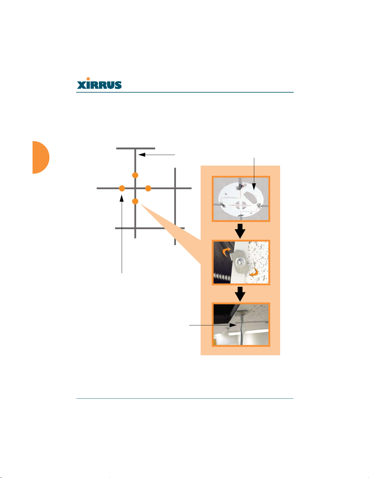
Wireless LAN Array
Attaching the T-Bar Clips
The T-bar clips are used to create four mounting points on the ceiling tile grid for
the Array mounting plate. Use the mounting template (provided) to find the
correct location for all four clamps. To attach the clamps, simply twist the clamps
onto the grid and tighten the screw post with a screwdriver.
T-bar clips (4 places)
Tighten the screw post
Ceiling tile grid
Tem pl at e
Figure 25. Attaching the T-Bar Clips
44 Installing the Xirrus Array
Page 80
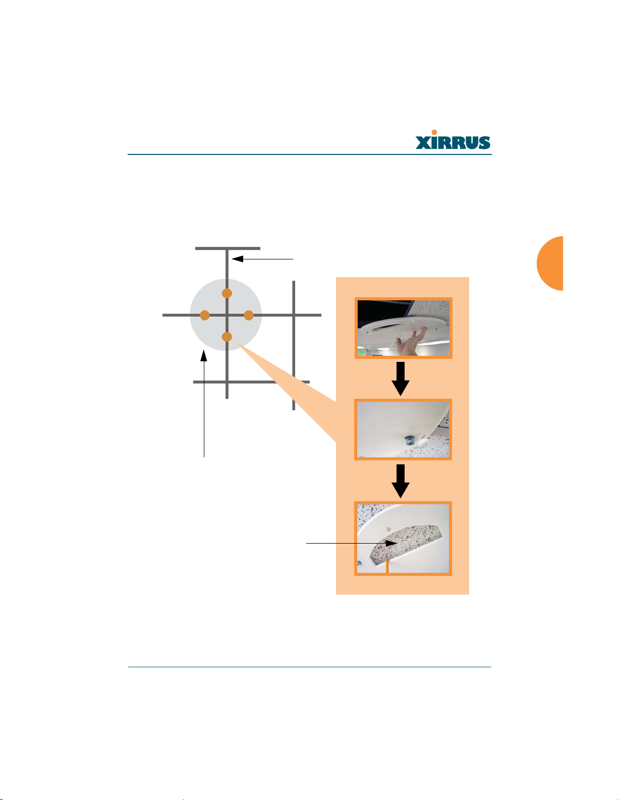
Wireless LAN Array
Installing the Mounting Plate
If necessary, orient the mounting plate (see “Attaching the T-Bar Clips” on
page 44) and locate the plate on the four screw posts. Secure the mounting plate to
the four clamps using the nuts provided. Once the mounting plate is secured, cut
an access hole in the ceiling tile for the cables.
Tile grid
Mounting Plate
Cut an access hole here
Figure 26. Installing the Mounting Plate (XS-3900 shown)
Installing the Xirrus Array 45
Page 81
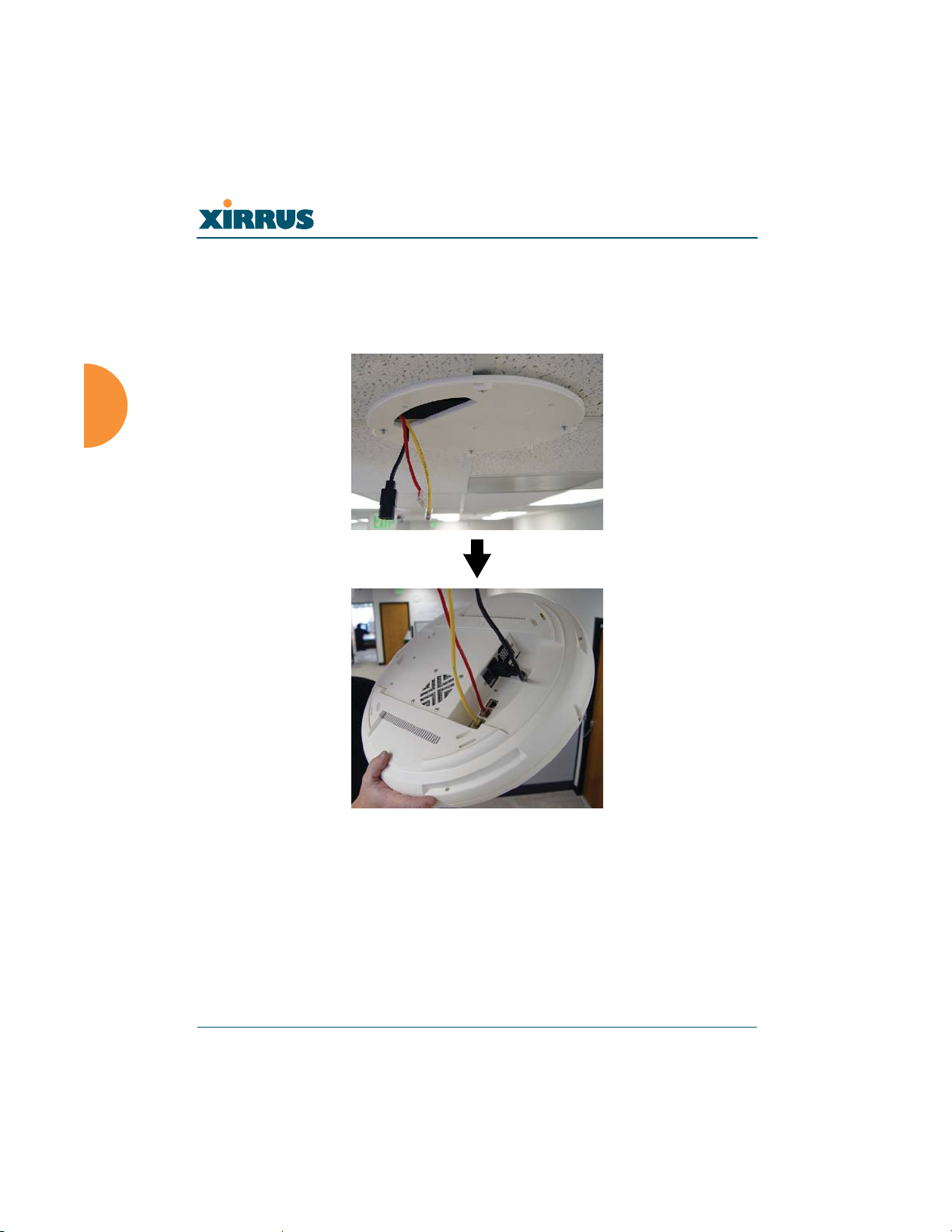
Wireless LAN Array
Connecting the Cables
Feed the power and Ethernet cables through the access hole in the tile and the
mounting plate (XS-3900), then connect the cables to the unit. See also, “Wiring
Considerations” on page 42.
Figure 27. Connecting the Cables
When the cables are connected, turn on the power switch—before attaching the
unit to the mounting plate (next step). Verify that the Ethernet link LED lights and
the LED boot sequence begins. The radio LEDs on the front of the unit will
illuminate in rotation, indicating that the Xirrus Array software is loading and the
unit is functioning correctly.
46 Installing the Xirrus Array
Page 82
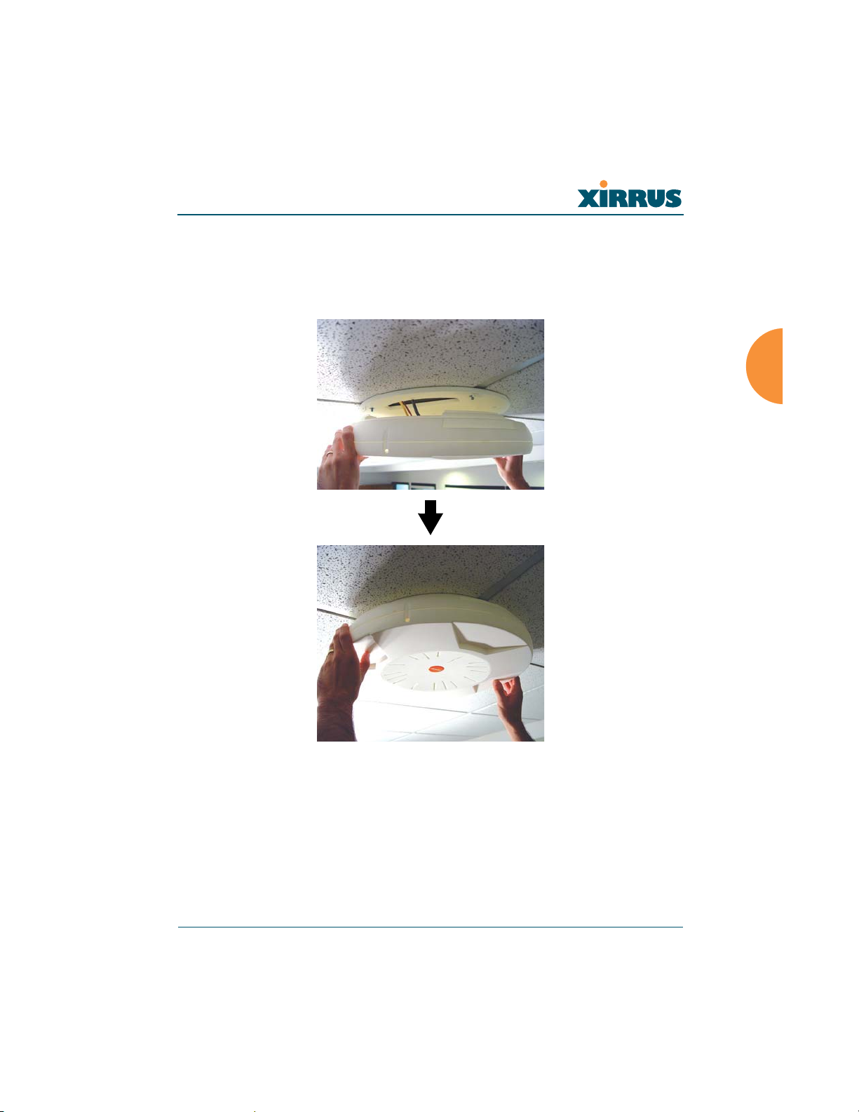
Wireless LAN Array
Attaching the Array to the Mounting Plate (XS-3900)
Align the port recess on the Array with the access hole in the mounting plate, then
connect the Array with the lugs on the mounting plate (4 places) and turn the
Array clockwise to lock the unit into place (similar to a smoke detector).
Figure 28. Attaching the Unit (XS-3900)
Installing the Xirrus Array 47
Page 83
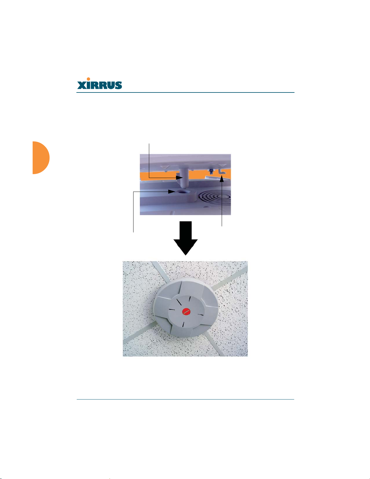
Wireless LAN Array
Attaching the Array to the Mounting Plate (XS-3500)
Align the XS-3500 Wireless LAN Array with the key post on the mounting plate,
then turn the Array to the right to lock the unit into place at the 4 lugs—similar to
a smoke detector.
Key post
Lug
Alignment hole
Figure 29. Attaching the Unit (XS-3500)
48 Installing the Xirrus Array
Page 84

Wireless LAN Array
Securing the Array
For added security, there is a locking bracket incorporated into the mounting
plate, which will accept a small luggage-style padlock (if desired). There is also a
Kensington lock slot located near the Ethernet ports. In addition, the mounting
plate incorporates a positive locking tab that prevents the unit from being
inadvertently released.
Locking bracket
Figure 30. Securing the Array
Now that the Array is physically installed, you must run the Express Setup
procedure from the unit’s Web Management Interface to enable the radios and
establish initial system configuration settings. Go to “Powering Up the Xirrus
Wireless LAN Array” on page 51.
Installing the Xirrus Array 49
Page 85

Wireless LAN Array
Dismounting the Array
To dismount the Array, place your fingers so as to increase the space between the
Array and the mounting plate at the positions indicated by the decals on the
mounting plate—these are aligned with IAPs (radios) abg1 and abg3, as indicated
on the clock-face of the Array.
a12
a11
abg4
a1
abg1
a9
a10
a8
abg3
a7
a6
Figure 31. IAP Positions (XS-3900)
a2
a3
a4
abg2
a5
50 Installing the Xirrus Array
Page 86
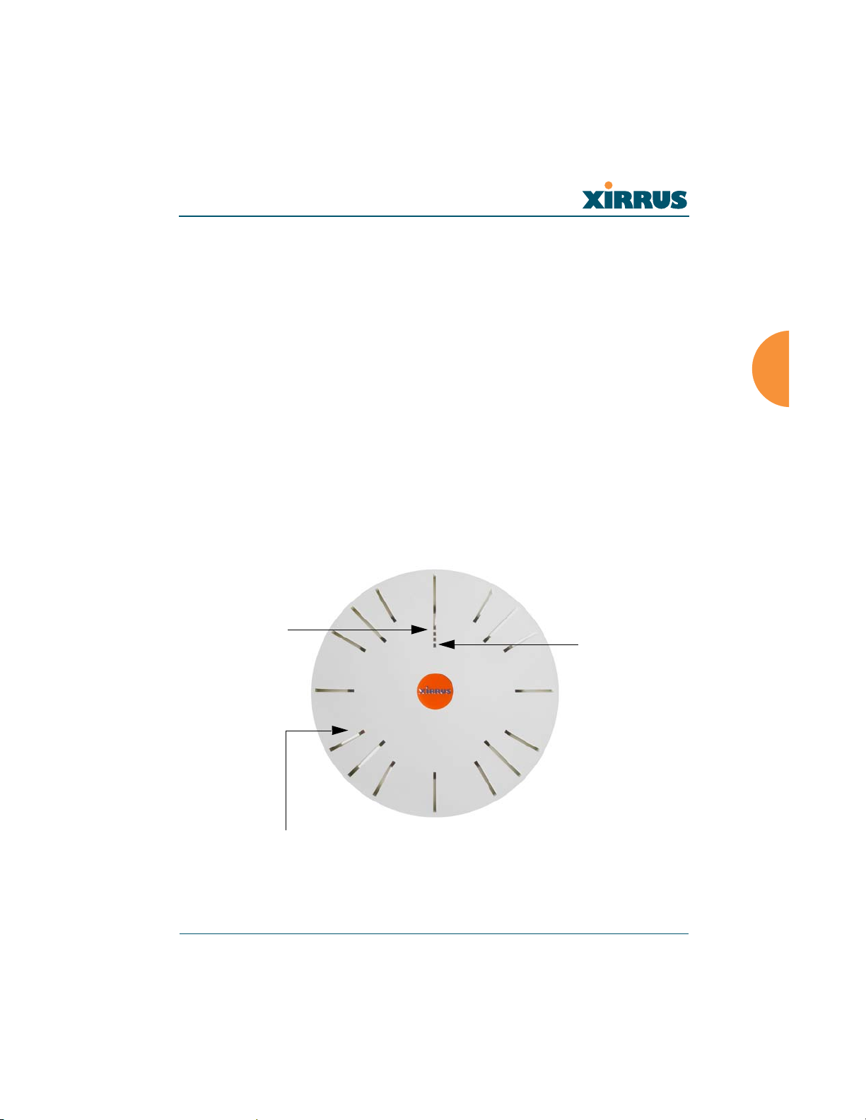
Wireless LAN Array
Powering Up the Xirrus Wireless LAN Array
When powering up, the Array follows a specific sequence of LED patterns
showing the boot progress, and following a successful boot will provide extensive
status information. The normal boot sequence is as follows:
1. The green status LED will light first, showing a steady flashing while the
unit boots. In the event of a boot failure, this LED will change to flashing
red.
2. The Ethernet Link/Activity LEDs on the underside of the Array will light
for those ports connected to the network.
3. All IAP radio LEDs will light simultaneously.
4. While the Array is booting, a sequential LED pattern will cycle through
all the radio LEDs.
5. When the Array completes boot, the status LED will show a steady green,
and all radio lights will show the current state of those radios.
Ethernet
Activity LEDs
Status LED
IAP LEDs (x16)
Figure 32. LED Locations (XS-3900)
Installing the Xirrus Array 51
Page 87
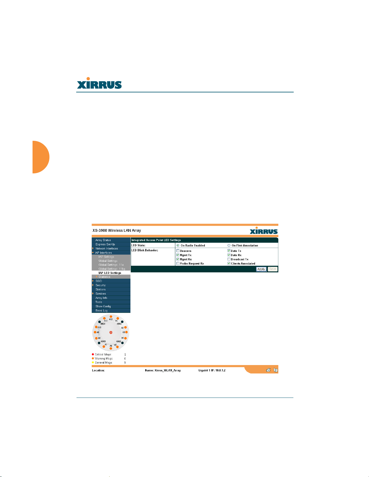
Wireless LAN Array
Once the unit is fully booted the default IAP LED display will be as follows:
z IAP radio LEDs that are enabled will show a steady orange for 802.11a
radios, or green for 802.11b/g radios.
z Once a client associates with an individual IAP, that LED will show a
slow flash (heartbeat) pattern.
z When data is transmitted or received by an IAP, that IAP’s LED will flash.
The rate of flashing changes with the number of packets sent or received
per second—the LED will flash more quickly with a greater number of
packets per second and more slowly with lower numbers of packets per
second.
These settings may be altered or disabled entirely for diagnostic purposes or for
personal preference. Changes are made via the Array’s Command Line Interface
or the Web Management Interface—refer to “IAP LED Settings” on page 103.
Figure 33. WMI: IAP LED Settings Page
52 Installing the Xirrus Array
Page 88
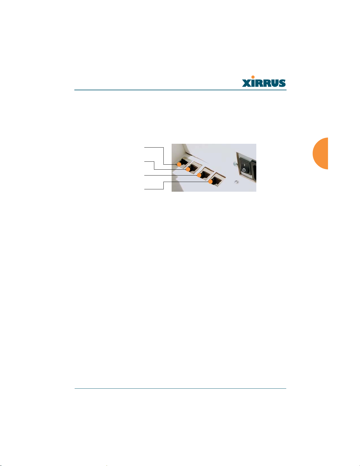
Wireless LAN Array
Establishing Communication with the Array
The Array can be configured through the Command Line Interface (CLI) or the
graphical Web Management Interface (WMI). You can use the CLI via the serial
management port, the Fast Ethernet port, or either of the Gigabit Ethernet ports.
You can use the WMI via any of the Array’s Ethernet ports.
Serial
Fast Ethernet
Gigabit 1
Gigabit 2
Figure 34. Network Interface Ports
Using the Serial Port
If using the serial port to make your connection, use serial settings of 8 bits, no
parity, 1 stop bit (8N1) and a speed setting of 115200 baud. Use the
communication package of your choice.
Using the Ethernet Ports
If the Array is booted and does not receive DHCP addresses on either the Fast
Ethernet or Gigabit Ethernet ports, the Fast Ethernet port will default to an IP
address of 10.0.0.1 and both Gigabit Ethernet ports will default to 10.0.1.1 and
10.0.2.1 respectively. If the Array is connected to a network that provides DHCP
addresses, the IP address can be determined by the following two methods:
1. Examine the DHCP tables on the server and find the addresses assigned
to the Array (Xirrus MAC addresses begin with 000F7D).
2. Query the Array using the CLI via the serial port. Use the show ethernet
command to view the IP addresses assigned to each port.
Logging In
When logging in to the Array, use the default user name and password—the
default user name is admin, and the default password is admin.
Installing the Xirrus Array 53
Page 89
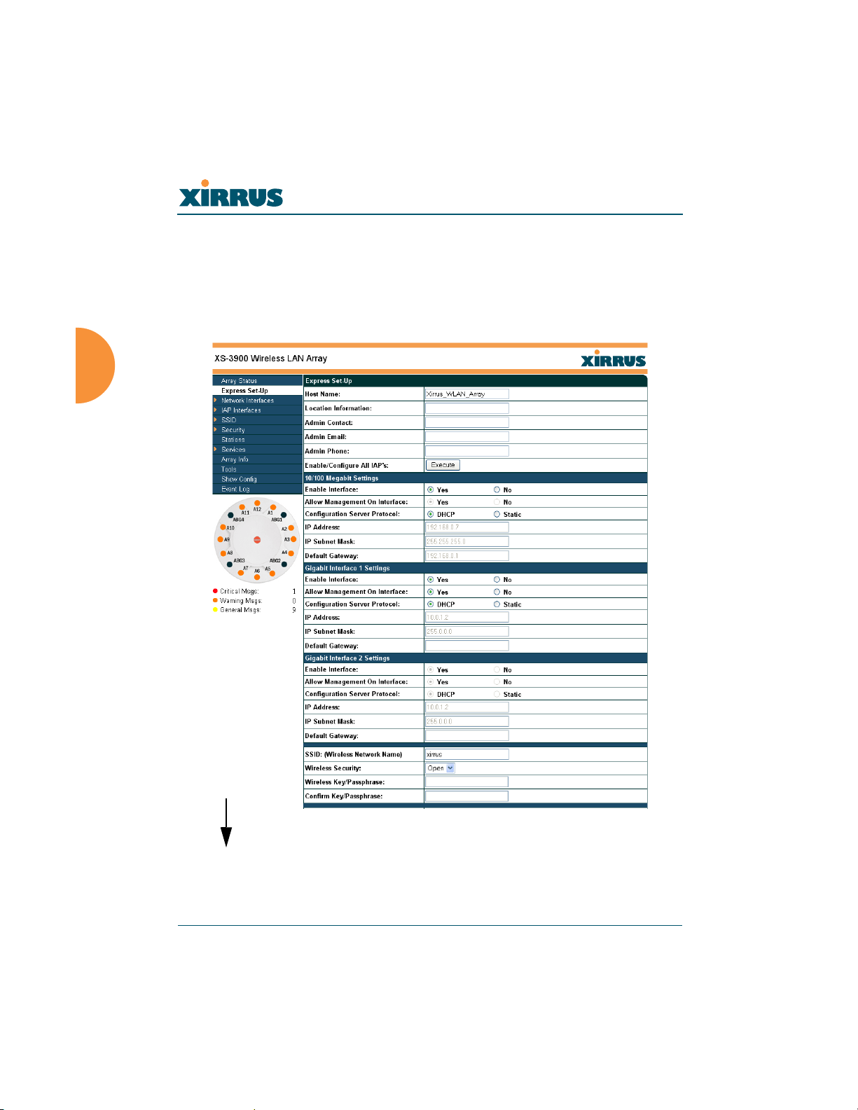
Wireless LAN Array
Performing the Express Setup Procedure
The Express Setup procedure allows you to establish global configuration settings
that will enable basic Array functionality. Any changes you make on this page
will affect all radios. When finished, click on the Apply button to apply the new
settings to this session, then click on the Save button to save your changes.
more ...
Figure 35. WMI: Express Setup Page (Part 1)
54 Installing the Xirrus Array
Page 90
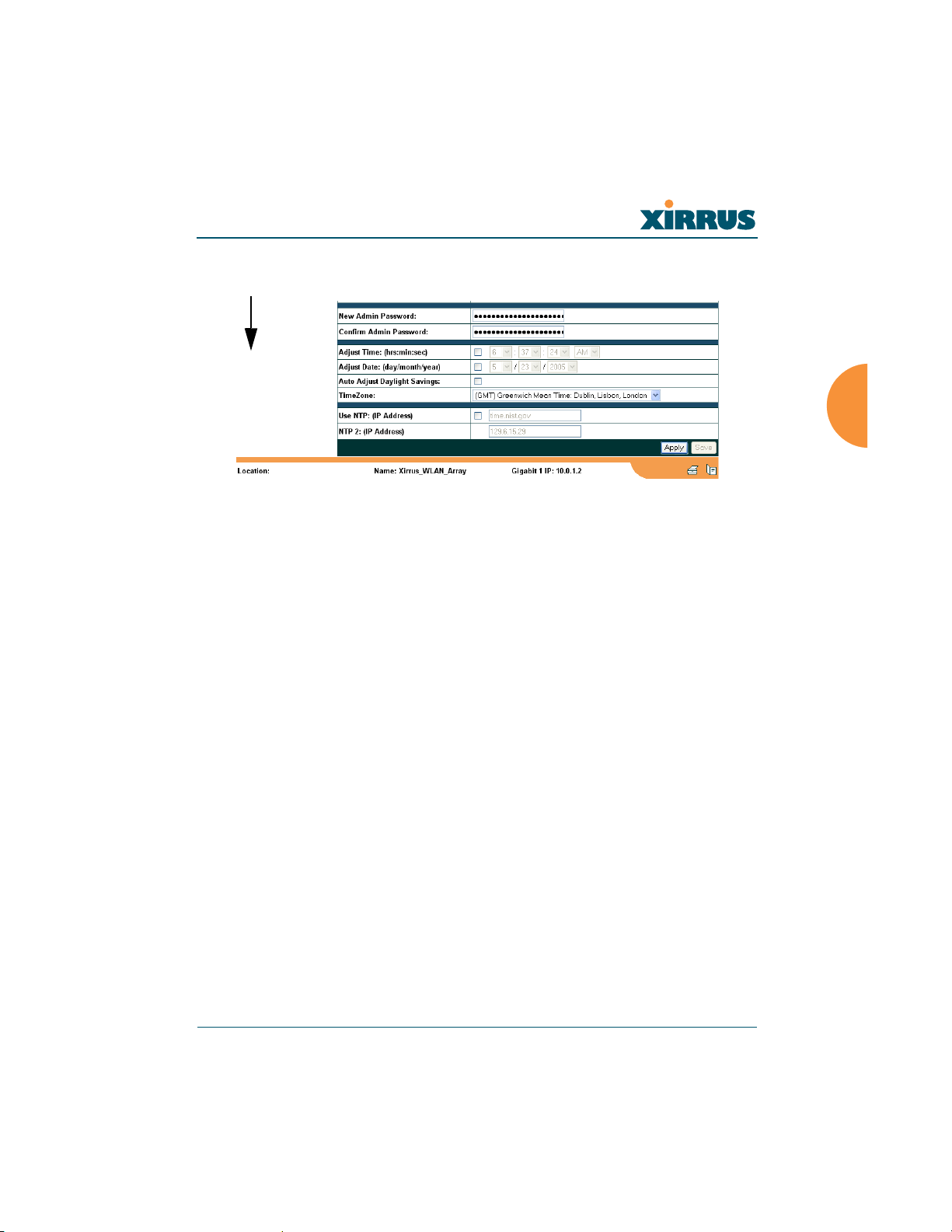
Wireless LAN Array
... continued
Figure 36. WMI: Express Setup Page (Part 2)
Procedure for Performing an Express Setup
1. Host Name: Specify a unique host name for this Array. The host name is
used to identify the Array on the network. Use a name that will be
meaningful within your network environment, up to 64 alphanumeric
characters.
2. Location Information: Enter a brief but meaningful description that
accurately defines the physical location of the Array. In an environment
where multiple units are installed, clear definitions for their locations are
important if you want to identify a specific unit.
3. Admin Contact: Enter the name and contact information of the person
who is responsible for administering the Array at the designated location.
4. Admin Email: Enter the email address of the admin contact you entered
in Step 3.
5. Admin Phone: Enter the telephone number of the admin contact you
entered in Step 3.
6. Enable/Configure All IAPs: Click on the Execute button to enable and
auto configure all IAPs (a message displays the countdown time—in
seconds—to complete the auto-configuration task).
Installing the Xirrus Array 55
Page 91

Wireless LAN Array
7. Configure the Fast Ethernet (10/100 Megabit), Gigabit 1 and Gigabit 2
network interfaces. The fields for each of these interfaces are the same,
and include:
a. Enable Interface: Choose Ye s to enable this network interface, or
choose No to disable the interface.
b. Allow Management on Interface: Choose Yes to allow management
of the Array via this network interface, or choose No to deny all
management privileges for this interface.
c. Configuration Server Protocol: Choose DHCP to instruct the Array
to use DHCP to assign IP addresses to the Array’s Ethernet interfaces,
or choose Static IP if you intend to enter IP addresses manually. If
you choose the Static IP option, you must enter the following
information:
z IP Address: Enter a valid IP address for this Array. To use
any of the remote connections (Web, SNMP, or SSH), a valid
IP address must be used.
z IP Subnet Mask: Enter a valid IP address for the subnet
mask (the default is 255.255.255.0). The subnet mask defines
the number of IP addresses that are available on the routed
subnet where the Array is located.
z Default Gateway: Enter a valid IP address for the default
gateway. This is the IP address of the router that the Array
uses to forward data to other networks.
8. SSID (Wireless Network Name): The SSID (Service Set Identifier) is a
unique name that identifies a wireless network. All devices attempting to
connect to a specific WLAN must use the same SSID. The default for this
field is “xirrus.”
For additional information about SSIDs, go to the Multiple SSIDs section
of “Frequently Asked Questions” on page 222.
9. Wireless Security: Select the desired wireless security scheme (Open,
WEP or WPA). Make your selection from the choices available in the pull-
down list.
56 Installing the Xirrus Array
Page 92

Wireless LAN Array
Open
This option offers no data encryption and is not recommended,
though you might choose this option if clients are required to use a
VPN connection through a secure SSH utility, like PuTTy.
WEP (Wired Equivalent Privacy)
An optional IEEE 802.11 function that offers frame transmission
privacy similar to a wired network. WEP generates secret shared
encryption keys that both source and destination stations can use to
alter frame bits to avoid disclosure to eavesdroppers.
WPA (Wi-Fi Protected Access)
A Wi-Fi Alliance standard that contains a subset of the IEEE 802.11i
standard, using TKIP or AES as an encryption method and 802.1X for
authentication. WPA is the stronger of the two wireless security
schemes.
For more information about security, including a full review of all
security options and settings, go to “Security Management” on page 113.
#
10. Wireless Key/Passphrase: Depending on the wireless security scheme
you selected, enter a unique WEP key or WPA passphrase.
a. Confirm Key/Passphrase: If you entered a WEP key or WPA
11. New Admin Password: If desired, enter a new administration password
for managing this Array. Choose a password that is not obvious, and one
that you can remember. If you forget your password, you must reset the
Array to its factory defaults so that the password is reset to admin (its
default setting).
a. Confirm Admin Password: If you entered a new administration
Installing the Xirrus Array 57
Security settings will only take effect if they are assigned to a specific
SSID. Refer to “SSID” on page 107.
passphrase, confirm it here.
password, confirm the new password here.
Page 93
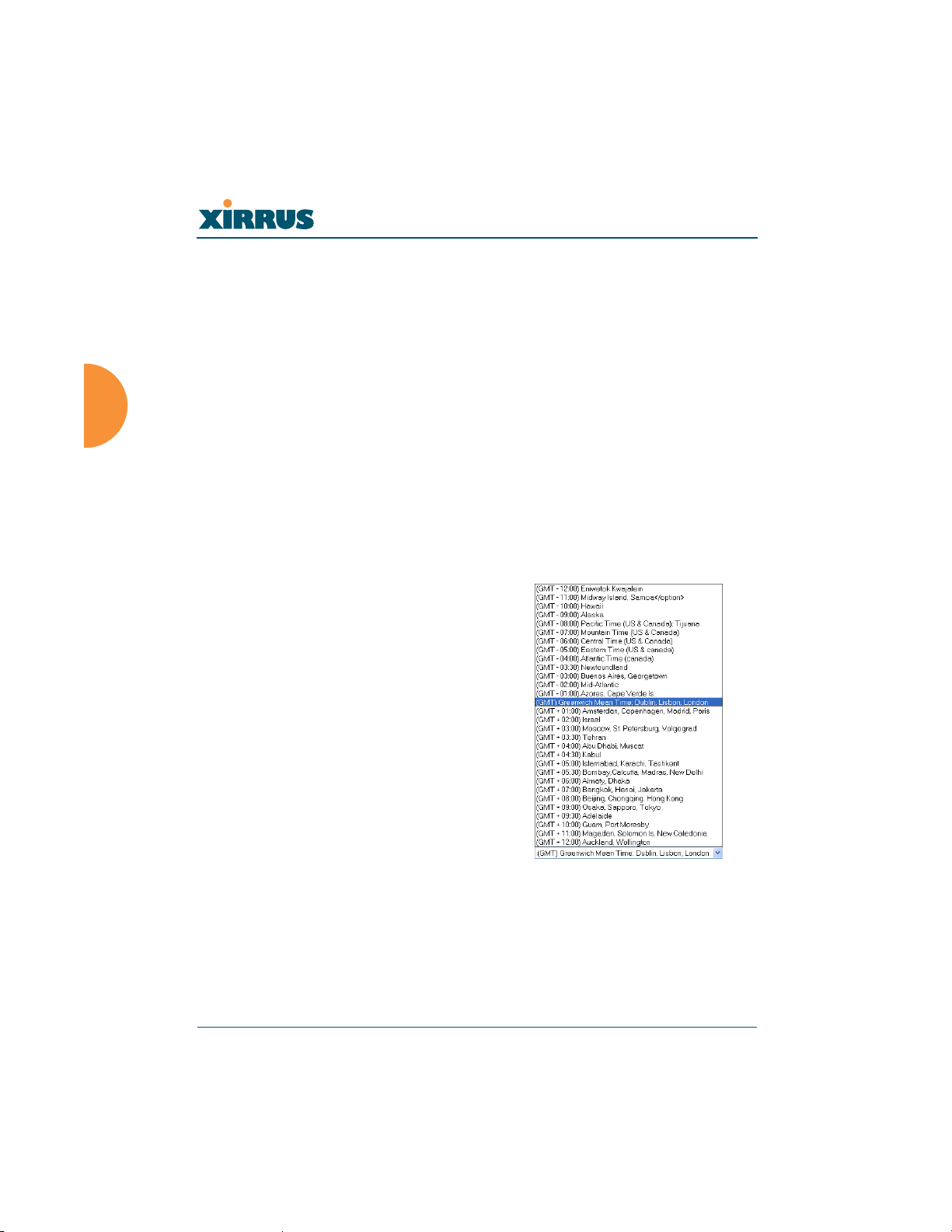
Wireless LAN Array
12. Adjust Time (hrs:min:sec): Check this box if you want to adjust the
current system time. When the box is checked, the time fields become
active. Enter the revised time (hours, minutes, seconds, am/pm) in the
corresponding fields. If you don’t want to adjust the current time, this box
should be left unchecked (default).
13. Adjust Date (day/month/year): Check this box if you want to adjust the
current system date. When the box is checked, the date fields become
active. Enter the revised date (day, month, year) in the corresponding
fields. If you don’t want to adjust the current date, this box should be left
unchecked (default).
14. Auto Adjust Daylight Savings: Check this box if you want the system to
adjust for daylight savings automatically, otherwise leave this box
unchecked (default).
15. Time Zone: Select a time zone
from the choices available in the
pull-down list.
Figure 37. WMI: Time Zones
58 Installing the Xirrus Array
Page 94
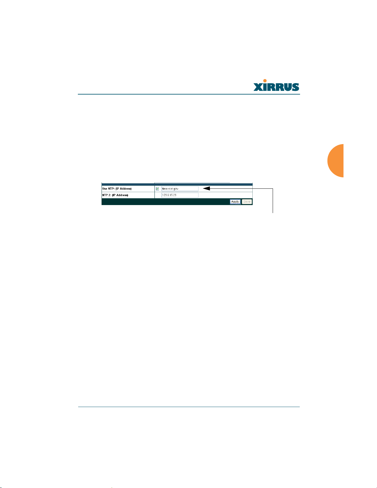
Wireless LAN Array
16. Use NTP (IP Address): Check this box if you want to use an NTP
(Network Time Protocol) server to synchronize the Array’s clock. This
ensures that syslog time-stamping is maintained across all units. Without
an NTP server assigned (no universal clock), each Array will use its own
internal clock and stamp times accordingly, which may result in
discrepancies. When this box is checked, the NTP and NTP 2 IP address
fields become active. If you don’t want to use an NTP server, leave this
box unchecked (default), otherwise enter the IP address or DNS name of
the NTP server.
NTP enabled
Figure 38. Enabling the NTP Feature
a. NTP 2 (IP Address): If you enabled the NTP option and the site is
using a secondary NTP server, enter the IP address or DNS name of
the secondary NTP server.
17. Click on the Apply button to apply the new settings to this session
18. Click on the Save button to save your changes (otherwise your new
settings will not take effect).
This ends the Express Setup procedure.
Installing the Xirrus Array 59
Page 95

Wireless LAN Array
Installing the XS-3900 Wall Mount Assembly
The wall mounting assembly is used to mount the XS-3900 Wireless LAN Array
on a wall, instead of the traditional ceiling mount—where mounting the Array on
the ceiling may be impractical at your location.
Kit Contents
The Wall Mounting Assembly kit includes the following items:
z 8 x SNAPTOGGLE™ toggle bolts (for attaching the wall bracket to the
wall)
z 4 x 1/4 inch bolt assemblies (for attaching the mounting plate to the wall
bracket)
z Wall M oun tin g Bracket
Tools Required
z Power drill
z 1/2 inch (13mm) drill bit
z Cross head screwdriver
z 1/4 inch nut wrench
z Pencil
z Level
60 Installing the Xirrus Array
Page 96
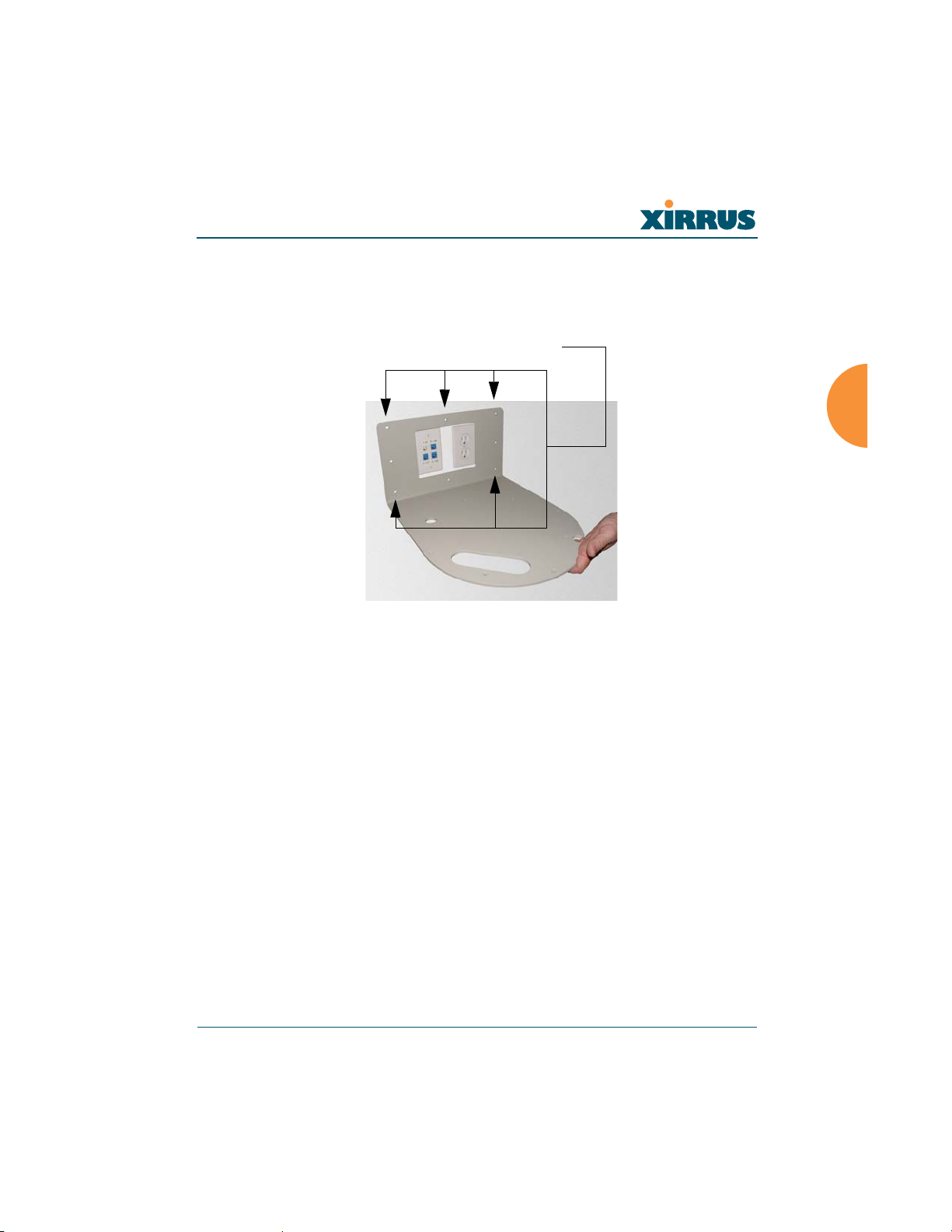
Wireless LAN Array
Mark the Wall Position
1. Use the Wall Mounting Bracket as a template and mark the locations on
the wall for the mounting holes.
Mark holes (at least 5 places)
Figure 39. Wall Mount—Marking the Holes
When marking the holes, ensure that the mounting plate is level—you
may need assistance.
#
Installing the Xirrus Array 61
The bracket must be secured to the wall in at least 5 places, using a minimum
of the top 3 holes and the 2 outside holes at the bottom. For maximum strength,
use all 8 mounting points (8 toggle bolts are provided).
Page 97

Wireless LAN Array
Install the SNAPTOGGLE™ Toggle Bolts
2. At the locations you marked in Step 1, drill a 1/2 inch (13mm) hole (there
must be a minimum clearance behind the wall of 1 7/8 inches (48mm).
3. (Refer to graphic A) Hold the metal channel flat alongside the plastic
straps and slide the channel through the hole.
A
C D
Figure 40. Installing the Toggle Bolts
B
4. (Refer to graphic B) Hold the strap handle between your thumb and
forefinger and pull towards you until the metal channel rests flush
behind the wall.
To achieve the maximum shear holding capability for the toggle bolt, orient the
metal channel so that the channel is vertical to the floor.
Using your other hand, now slide the plastic cap along the straps until the
flange of the cap is flush with wall.
The straps provide a one-way ratcheting mechanism (similar to a cable tie).
Ensure that the toggle bolt assembly is oriented correctly (vertical to the floor)
before sliding the plastic cap along the straps.
5. (Refer to graphic C) Break the straps at the wall, flush with the flange of
the cap. The straps can be broken by pushing them from side-to-side and
simply snapping them off.
62 Installing the Xirrus Array
Page 98

Wireless LAN Array
Graphic D shows a cutaway example of how the toggle bolt is used to
secure an item to the wall (in our case, the item is the Wall Mounting
Bracket—secured to the wall with a minimum of 5 toggle bolts.
Do not attach the Wall Mounting Bracket to the wall at this time.
Attach the Mounting Plate to the Wall Mounting Bracket
Secure the Wireless LAN Array’s mounting plate to the Wall Mounting
Bracket (4 places)—tighten the 4 bolt assemblies to a torque of 10–12 lbf.ft
(1.38–1.66 kgf.m). Do not overtighten the bolts.
Mounting Plate
Secure (x4 bolt assemblies)
Figure 41. Attaching the Wall Mounting Plate
Attach the Wall Mounting Bracket/Plate Assembly to the Wall
6. Secure the Wall Mounting Bracket (with attached Mounting Plate) to the
wall at the toggle bolt anchors you created in Steps 2 through 5—a
minimum of 5 places.
Installing the Xirrus Array 63
Page 99
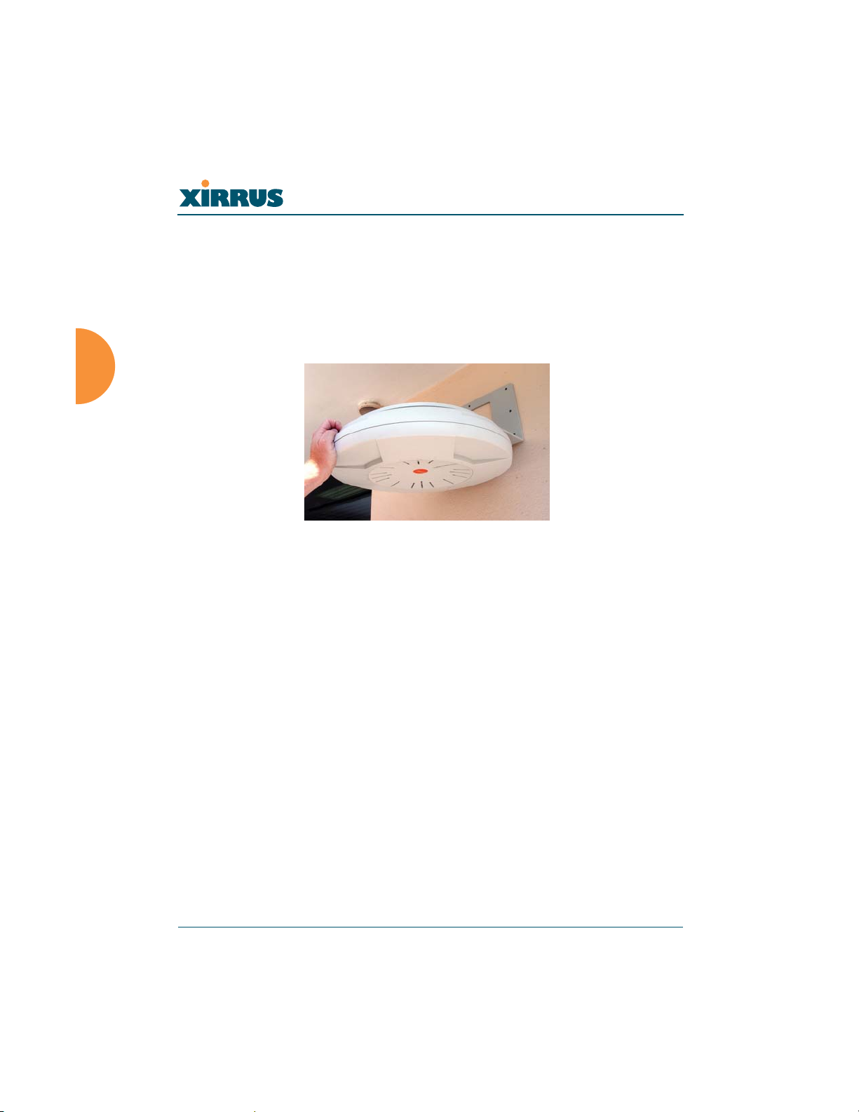
Wireless LAN Array
Mount the Array
The image opposite shows the orientation of the Wireless LAN Array when
mounted on a wall. It is not intended to show a fully installed Array.
7. Mount the Wireless LAN Array to the Wall Mounting Bracket in the same
way that you would mount the Array to a ceiling mount (the procedure is
identical).
Figure 42. Mounting the Array on a Wall
64 Installing the Xirrus Array
Page 100
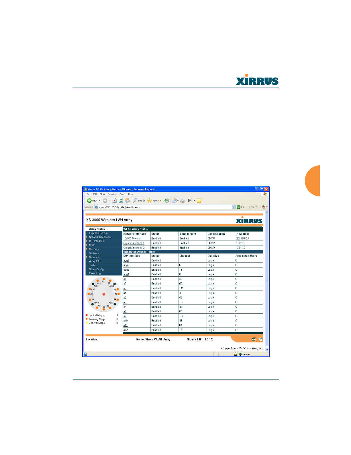
Wireless LAN Array
The Web Management Interface
This chapter provides an overview of the XS-3900’s embedded Web Management
Interface (WMI), used for establishing your network’s configuration settings and
wireless operating parameters.
An Overview
The WMI is an easy-to-use graphical interface to your Xirrus Array. It allows you
to configure the product to suit your individual requirements and ensure that the
unit functions efficiently and effectively.
Figure 43. Web Management Interface
The Web Management Interface 65
 Loading...