

Cambium Networks XI-AC867 Users Manual

Wireless Array
Configuring the
Wireless Array
The following topics include procedures for configuring the Array using the
product’s embedded Web Management Interface (WMI). Procedures have been
organized into functional areas that reflect the flow and content of the WMI.
The following WMI windows allow you to establish configuration parameters for
your Array, and include:
“Express Setup” on page 159
“Network” on page 165
“Services” on page 179
“VLANs” on page 204
“Tunnels” on page 209
“Security” on page 213
“SSIDs” on page 254
“Groups” on page 280
“IAPs” on page 287
“WDS” on page 358
“Filters” on page 365
“Clusters” on page 374
“Mobile” on page 380
After making changes to the configuration settings of an Array you must click the
Save button at the top of the configuration window, otherwise the changes
you make will not be applied the next time the Array is rebooted.
Configuring the Wireless Array 157
Some settings are only available if the Array’s license includes appropriate
features. If a setting is unavailable (grayed out), then your license does not
support the feature. See “About Licensing and Upgrades” on page 387.

Wireless Array
Note that the Configuration menu section may be collapsed down to hide the
headings under it by clicking it. Click again to display the headings. (See
Figure 39 on page 86.)
This chapter only discusses using the configuration windows on the Array. To
view status or use system tools on the Array, please see:
“Viewing Status on the Wireless Array” on page 91
“Using Tools on the Wireless Array” on page 385
158 Configuring the Wireless Array
Wireless Array
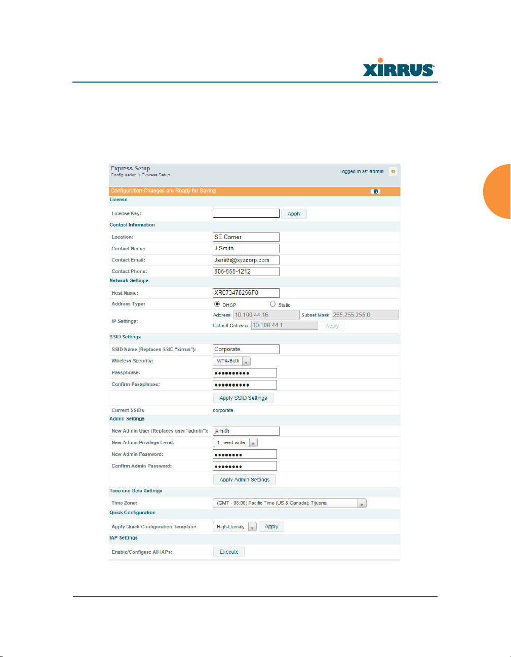
Express Setup
Initial Array configuration via XMS sets items such as SSIDs and security, as
described in “Zero-Touch Provisioning and Ongoing Management” on page 69.
This page allows you to see many of these values, or change them locally.
Figure 95. WMI: Express Setup
Configuring the Wireless Array 159

Wireless Array
When finished, click the Save button if you wish to make your changes
permanent.
Procedure for Performing an Express Setup
1. License Key: An unlicensed Array will automatically contact Xirrus to
obtain its license, if it has Internet connectivity. If you need to enter a
license manually, enter it here. See “Licensing” on page 74.
2. Configure the Contact Information settings.
a. Location: Enter a brief but meaningful description that accurately
defines the physical location of the Array. In an environment where
multiple units are installed, clear definitions for their locations are
important if you want to identify a specific unit.
b. Contact Name: Enter the name and contact information of the person
who is responsible for administering the Array at the designated
location.
c. Contact Email: Enter the email address of the admin contact you
entered in Step 3.
d. Contact Phone: Enter the telephone number of the admin contact you
entered in Step 3.
3. Configure the Network settings. Please see “Network Interfaces” on
page 166 for more information.
a. Host Name: Specify a unique host name for this Array. The host
name is used to identify the Array on the network. Use a name that
will be meaningful within your network environment, up to 64
alphanumeric characters. The default is the Array’s serial number.
b. Address Type: Choose DHCP to instruct the Array to use DHCP to
assign IP addresses to the Array’s Ethernet interfaces, or choose
Static if you intend to enter IP addresses manually. If you choose the
Static IP option, you must enter the following IP Settings:
c. IP Settings: If you choose the Static IP addressing option, enter the
following:
160 Configuring the Wireless Array

Wireless Array
• Address: Enter a valid IP address for this Array. To use a remote
• Subnet Mask: Enter a valid IP address for the subnet mask (the
• Default Gateway: Enter a valid IP address for the default
• Click the Apply button for this interface when done making IP
connection (Web, SNMP, or SSH), a valid IP address must be
used.
default is 255.255.255.0). The subnet mask defines the number of
IP addresses that are available on the routed subnet where the
Array is located.
gateway. This is the IP address of the router that the Array uses
to forward data to other networks.
changes.
4. SSID Settings: This section specifies the wireless network name and
For improved security, you should also take the additional steps described in
“Securing Low Level Access to the Array” on page 76.
security settings.
a. SSID Name is a unique name that identifies a wireless network. The
default SSID is xirrus. Entering a value in this field will replace the
this default SSID with the new name.
For additional information about SSIDs, go to the Multiple SSIDs
section of “Frequently Asked Questions” on page 492.
b. Wireless Security: Select the desired wireless security scheme (Open,
WEP or WPA). Make your selection from the choices available in the
pull-down list.
• Open — This option offers no data encryption and is not
recommended, though you might choose this option if clients are
required to use a VPN connection through a secure SSH utility,
like PuTTy.
• WEP (Wired Equivalent Privacy) — An optional IEEE 802.11
function that offers frame transmission privacy similar to a wired
network. WEP generates secret shared encryption keys that both
Configuring the Wireless Array 161

Wireless Array
source and destination stations can use to alter frame bits to
avoid disclosure to eavesdroppers.
• WPA (Wi-Fi Protected Access) — A Wi-Fi Alliance standard that
contains a subset of the IEEE 802.11i standard, using TKIP or AES
as an encryption method and 802.1x for authentication. WPA is
the stronger of the two wireless security schemes.
• WPA2 (Wi-Fi Protected Access 2) — WPA2 is the follow-on
security method to WPA for wireless networks and provides
stronger data protection and network access control. It offers
Enterprise and consumer Wi-Fi users with a high level of
assurance that only authorized users can access their wireless
networks. Like WPA, WPA2 is designed to secure all versions of
802.11 devices, including 802.11a, 802.11b, 802.11g, and 802.11n,
multi-band and multi-mode.
• WPA-Both (WPA and WPA2) — This option makes use of both
WPA and WPA2.
For more information about security, including a full review of all
security options and settings, go to “Understanding Security” on
page 214.
c. WEP Encryption Key/WPA Passphrase: Depending on the wireless
security scheme you selected, enter a unique WEP key or WPA
passphrase. This field and the one below only appear if you select a
Wireless Security option other than Open.
d. Confirm Encryption Key/Passphrase: If you entered a WEP key or
WPA passphrase, confirm it here.
e. Click Apply SSID Settings when done.
f. Current SSIDs: This lists all of the currently defined SSIDs for you
(regardless of whether they are enabled or not).
162 Configuring the Wireless Array

Wireless Array
5. Admin Settings: This section allows you to change the default admin
username, password, and privileges for the Array. You may change the
password and leave the user name as is, but we suggest that you change
both to improve Array security.
a. New Admin User (Replaces user “admin”): Enter the name of a new
administrator user account. Be sure to record the new account name
and password, because the default admin user will be deleted! Note
that the Array also offers the option of authenticating administrators
using a RADIUS server (see “Admin Management” on page 219)).
b. New Admin Privilege Level: By default, the new administrator will
have read/write privileges on the Array (i.e., the new user will be
able to change the configuration of the Array). If you wish the new
account to have different privileges, select the desired level from the
drop-down list. For more information about user privileges, please
see “Admin Privileges” on page 221. Take care to make sure to leave
yourself enough read/write privileges on at least one account to be
able to administer the Array.
c. New Admin Password: Enter a new administration password for
managing this Array. If you forget this password, you must reset the
Array to its factory defaults so that the password is reset to admin (its
default setting).
d. Confirm Admin Password: If you entered a new administration
password, confirm the new password here.
e. Click Apply Admin Settings when done.
6. Time and Date Settings: System time is synchronized using NTP
(Network Time Protocol) by default. Use the pull-down menu to select
the Time Zone.
7. Quick Configuration: This offers predefined configuration options such
as Classroom and High-Density that capture best practices from years of
field experience. If one of the options in the drop-down list is appropriate
Configuring the Wireless Array 163
Wireless Array
LED on
to your deployment, select it and click Apply. For example, the High-
Density option uses best practices to configure the Array for high density
settings such as lecture halls, convention centers, stadiums, etc.
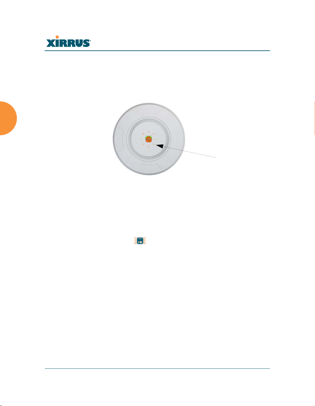
8. IAP Settings:
Figure 96. LEDs are Switched On
Enable/Configure All IAPs: Click on the Execute button to enable and
auto configure all IAPs (a message displays the countdown time — in
seconds — to complete the auto-configuration task). When an IAP is
enabled, its LED is switched on.
9. Click the Save button at the upper right to make your changes
permanent, i.e., these settings will still be in effect after a reboot.
164 Configuring the Wireless Array
Wireless Array
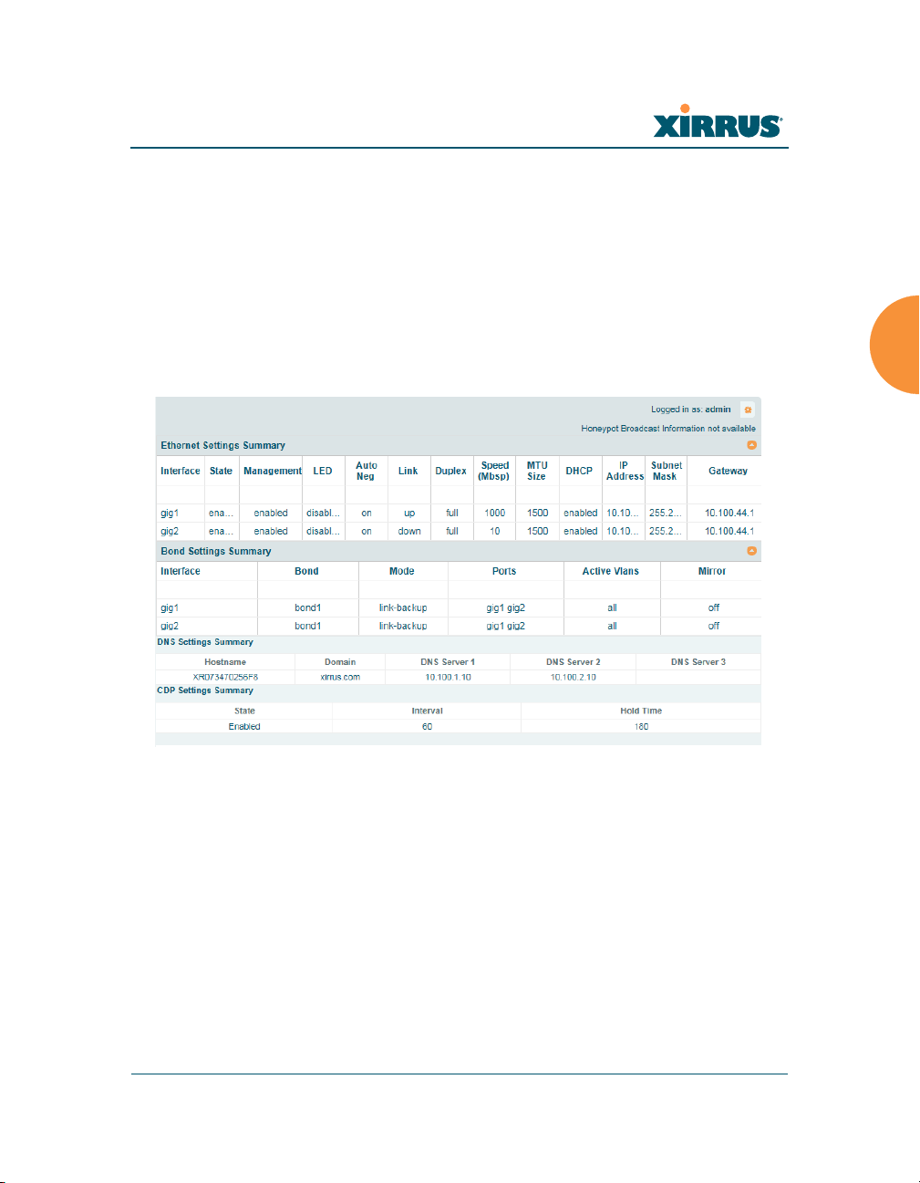
Network
This is a status-only window that provides a snapshot of the configuration
settings currently established for the Ethernet interfaces. DNS Settings and CDP
Settings (Cisco Discovery Protocol) are summarized as well. You must go to the
appropriate configuration window to make changes to any of the settings
displayed here (configuration changes cannot be made from this window). You
can click on any item in the Interface column to “jump” to the associated
configuration window.
Figure 97. Network Interfaces
WMI windows that allow you to change or view configuration settings associated
with the network interfaces include:
“Network Interfaces” on page 166
“Bonds and Bridging” on page 169
“DNS Settings” on page 176
“CDP Settings” on page 177
Configuring the Wireless Array 165
Wireless Array
See Also
DNS Settings
Network Interfaces
Network Status Windows
Spanning Tree Status
Network Statistics
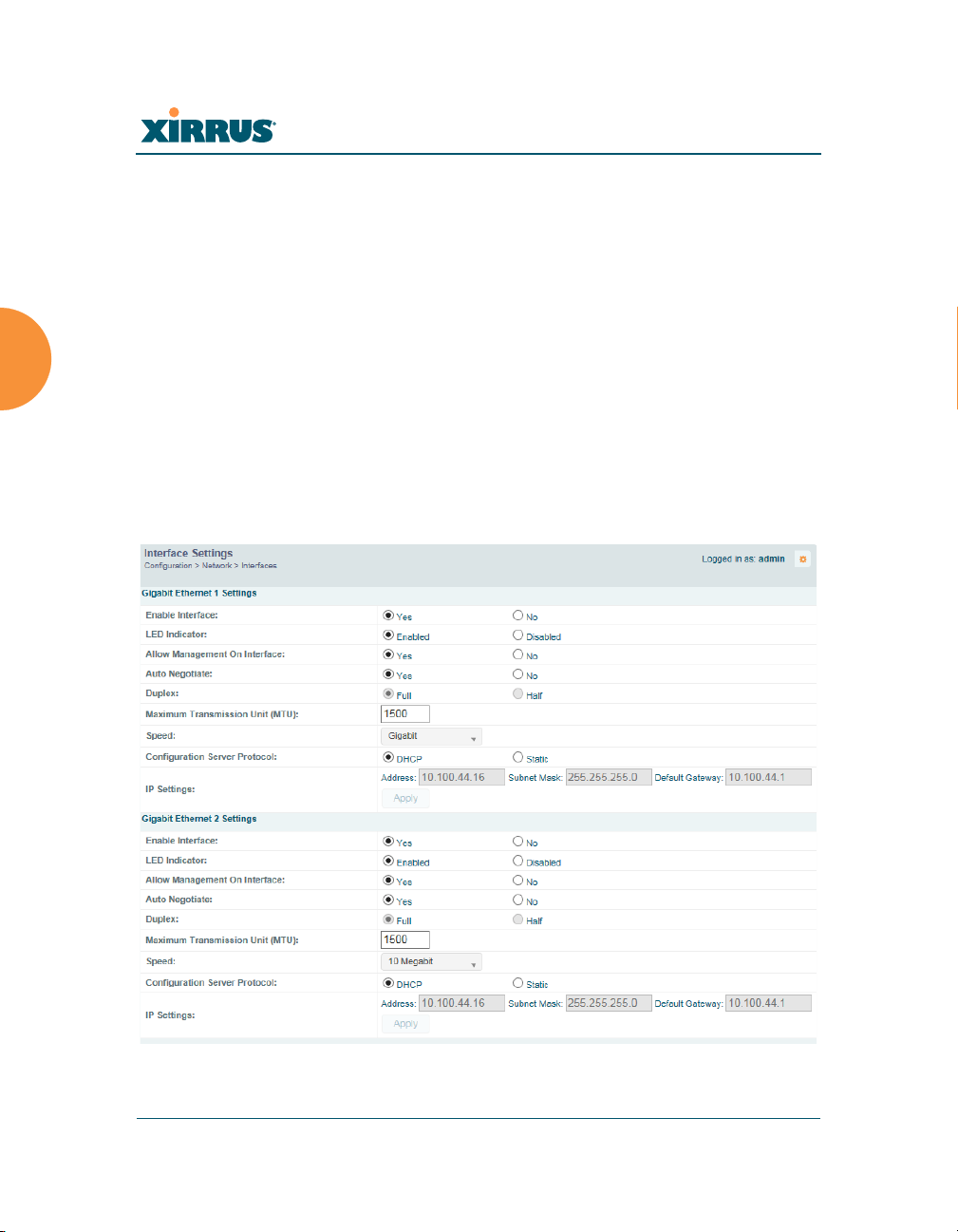
Network Interfaces
XR-500, XR-1000, and some XR-2000 Series Arrays have one Gigabit Ethernet
interface, while XR- 600, XR-4000 and some XR-2000 Series Arrays have two, and
XR-6000 Series models have four. This window allows you to establish
configuration settings for these interfaces.
Figure 98. Network Settings
166 Configuring the Wireless Array

Wireless Array
When finished making changes, click the Save button if you wish to make
your changes permanent. When the status of a port changes, a Syslog entry is
created describing the change.
Network Interface Ports
For the location of network interface ports on the underside of an XR Series
Array, see the illustrations starting with Figure 32 on page 71.
Procedure for Configuring the Network Interfaces
Configure the Gigabit network interfaces. The fields for each of these interfaces
are the same, and include:
1. Enable Interface: Choose Yes to enable this network interface, or choose
No to disable the interface.
2. LED Indicator: Choose Enabled to allow the LED for this interface to
blink with traffic on the port, or choose Disabled to turn the LED off.
The LED will still light during the boot sequence, then turn off. This
option is only available for the Gigabit interfaces.
3. Allow Management on Interface: Choose Yes to allow management of
this Array via the selected network interface, or choose No to deny all
management privileges for this interface.
4. Auto Negotiate: This feature allows the Array to negotiate the best
Configuring the Wireless Array 167
For improved security, you should also take the additional steps described in
“Securing Low Level Access to the Array” on page 76.
transmission rates automatically. Choose Ye s to enable this feature, or
choose No to disable this feature — the default is enabled. If you disable
the Auto Negotiate feature, you must define the Duplex and Speed
options manually (otherwise these options are not available). Both sides
of the link must have the same values for the following settings, or the
connection will have errors.
a. Duplex: Full-duplex mode transmits data in two directions
simultaneously (for example, a telephone is a full-duplex device

Wireless Array
because both parties can talk and be heard at the same time). Halfduplex allows data transmission in one direction at a time only (for
example, a walkie-talkie is a half-duplex device). If the AutoNegotiate feature is disabled, you can manually choose Half or Full
duplex for your data transmission preference.
b. MTU: the Maximum Transmission Unit size. This is the largest packet
size (in bytes) that the interface can pass along.
c. Speed: If the Auto-Negotiate feature is disabled, you must manually
choose the data transmission speed from the pull-down list. For the
Gigabit interfaces the options are 10 Megabit or 100 Megabit. (Note
that 1000 Megabit speed can only be set by Auto-Negotiation.)
5. Configuration Server Protocol / IP Settings: Choose DHCP to instruct
the Array to use DHCP when assigning IP addresses to the Array, or
choose Static IP if you intend to enter IP addresses manually. If you select
the Static IP option you must specify the IP address, IP subnet mask and
default gateway.
a. Address: If you selected the Static IP option, enter a valid IP address
for the Array. To use any of the remote connections (Web, SNMP, or
SSH), a valid IP address must be established.
b. Subnet Mask: If you selected the Static IP option, enter a valid IP
address for the subnet mask (the default for Class C is 255.255.255.0).
The subnet mask defines the number of IP addresses that are
available on the routed subnet where the Array is located.
c. Default Gateway: If you selected the Static IP option, enter a valid IP
address for the default gateway. This is the IP address of the router
that the Array uses to send data to other networks. (You don’t need to
enter the gateway if it is on the same subnet as the Array.)
d. Click the Apply button for this interface when done making IP
changes.
6. When done configuring all interfaces as desired, click the Save button
if you wish to make your changes permanent.
168 Configuring the Wireless Array
Wireless Array
See Also
Bonds and Bridging
DNS Settings
Network
Network Statistics
Spanning Tree Status
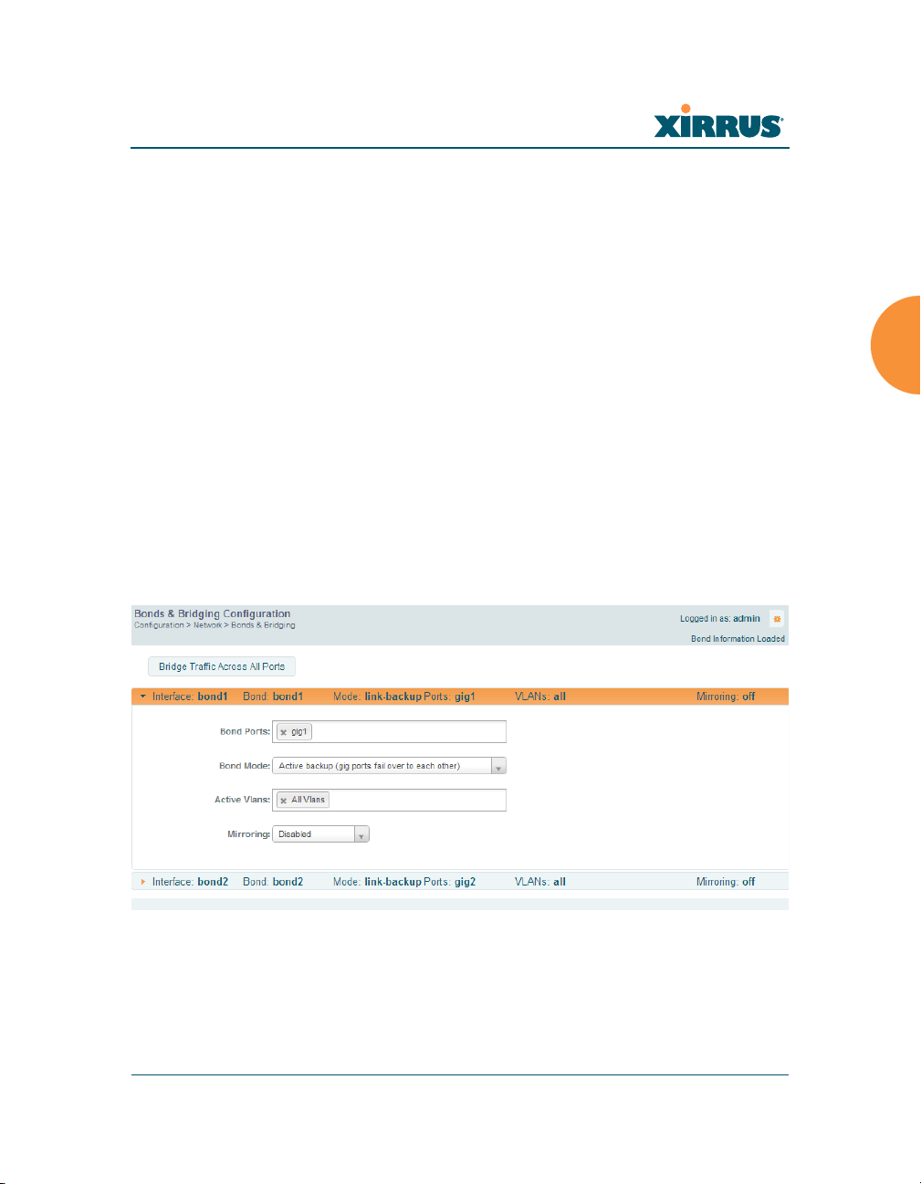
Bonds and Bridging
On models with more than one Gigabit port these ports may be bonded, i.e.
configured to work together in sets. For example, one port may provide active
backup or load balancing for another, or other options as described in this section.
XR-6000 Series Arrays have four Gigabit ports, and you may specify which ports
are bonded to work together as a pair. You may also select more than two ports to
work together in one group.
A special option lets you configure bridging between the gigabit ports on an
Array that has two of these ports.
Figure 99. Network Bonds and Bridging
You may use the mirror option to have all the traffic that is ingressing and
egressing one bond be transmitted by the bond you are configuring. For example,
if you configure Bond2 to mirror Bond1, then all traffic going in and out of
Configuring the Wireless Array 169
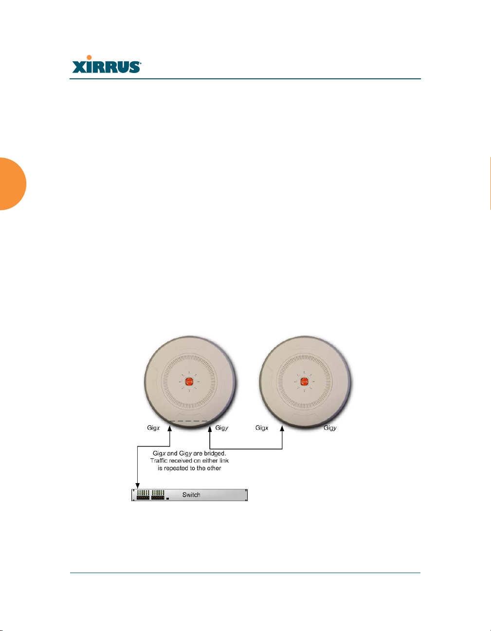
Wireless Array
Bridging traffic
Bond1’s Gigabit ports will be transmitted out of Bond2’s Gigabit ports. This way
of duplicating one bond’s traffic to another bond is very useful for
troubleshooting with a network analyzer.
Procedure for Configuring Network Bonds
Configure the bonding behavior of the Gigabit network interfaces. The fields for
each of these bonds are the same, and include:
1. Bridge Traffic Across All Ports: Click this for Layer 2 bridging between
If a set of Gigabit ports have been bonded, the IP address, IP mask, IP
gateway, IP DHCP, and Management settings are shared between bonded
ports. Any changes you make to these settings on one member will be
reflected in the settings of the other members. Other settings may be
configured individually.
all Gigabit ports. (Figure 100)
Figure 100. Bridging Traffic
170 Configuring the Wireless Array

Wireless Array
Traffic received on Gigx is transmitted by Gigy; similarly, traffic received
on Gigy is transmitted by Gigx. The Array acts as a wired bridge—this
allows Arrays to be chained and still maintain wired connectivity.
Each Array in a chain must have power supplied to its PoE port from a
compatible power injector or powered switch port. An Array does not
supply power to another Array.
When bridging is enabled, it configures the following bond settings for
each bond. Do not make any manual changes to these settings afterwards
if you wish to continue bridging.
• Bond Mode is set to Active Backup (the default value).
• Each port is in its own bond, by itself.
• Bond Mirror is Off.
• You will typically need to enable use of Spanning Tree manually, to
prevent network loops.
• Active VLANs is set to All.
A bridge between ports Gig1 and Gig2 sets Bond1 to contain only Gig1.
Bond2 contains only Gig2.
If you are bridging a chain of more than two Arrays, the endpoint Array
is not actually bridging. It can be left with the default settings—Bond1 is
set to Active Backup, and will contain Gig1 and Gig2.
Skip to Step 7 on page 175.
2. If you are not enabling bridging, configure the bonding behavior of the
Gigabit network interfaces as described in the following steps. The fields
for each of these bonds are the same.
3. Bond Mode: Select the desired behavior for a set of bonded Gigabit
Ethernet ports from the following options.
The modes below describe the relationship between a set of Gigabit
ports—for example, load balancing or active backup. Use the Bond Ports
field to select the ports that are bonded (set in Step 4). Two or more ports
Configuring the Wireless Array 171
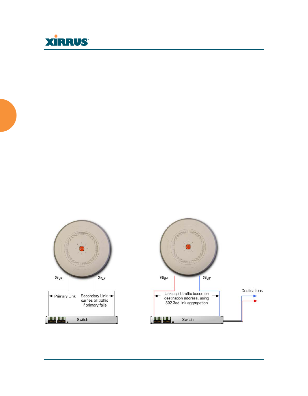
Wireless Array
(a) Active backup (b) Aggregate using 802.3ad
may be bonded. You may also include just one single port in a bond—this
is useful for mirroring one Gigabit port to another port (Step c on
page 174). In Arrays that have four Gigabit ports, you have the option of
bonding three or four ports together. In this discussion, we call two ports
that are bonded Gigx and Gigy.
a. Active Backup (gig ports fail over to each other) — This mode
provides fault tolerance and is the default mode. Gigx acts as the
primary link. Gigy is the backup link and is passive. Gigy assumes
the IP properties of Gigx. If Gigx fails, the Array automatically fails
over to Gigy. When a failover occurs in this mode, Gigy issues
gratuitous ARPs to allow it to substitute for Gigx at Layer 3 as well as
Layer 2. See Figure 101 (a). You may include more than two ports in
the bond with Active Backup to provide additional fault tolerance.
For example, if you have three Gigabit ports configured in a bond, if
the first two ports in the bond were to go down, the Array would fail
over traffic to the third Gigabit port.
Figure 101. Port Modes (a, b)
172 Configuring the Wireless Array
Wireless Array
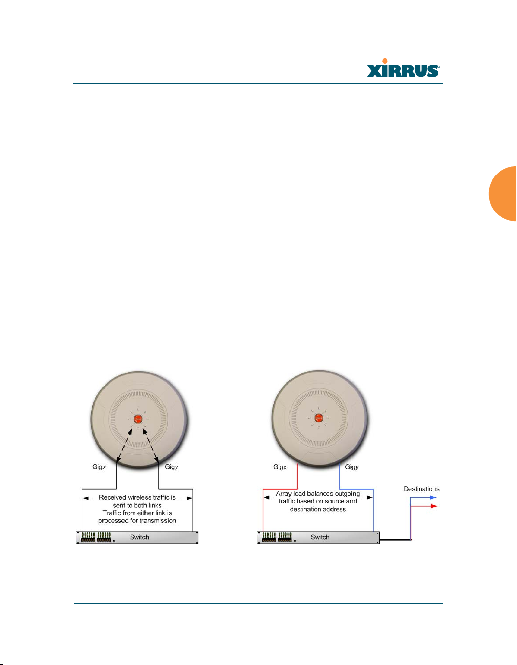
(c) Transmit on all ports (d) Load balance traffic
b. Aggregate Traffic from gig ports using 802.3ad — The Array sends
network traffic across all member Gigabit ports to increase link speed
to the network. These ports act as a single logical interface, using a
load balancing algorithm to balance traffic across the ports. For nonIP traffic (such as ARP), the last byte of the destination MAC address
is used to do the calculation. If the packet is a fragment or not TCP or
UDP, the source and destination IP addresses are used to do the
calculation. If the packet is TCP or UDP over IP then the source IP
address, destination IP address, source port number and destination
port number are all used to do the calculation. The network switch
must also support 802.3ad. If a port fails, the connection degrades
gracefully — the other port still transmits. See Figure 101 (b).
c. Transmit Traffic on all gig ports — Transmits incoming traffic on all
Gigabit ports. Any traffic received on Gigabit ports is sent to the
onboard processor. This mode provides fault tolerance. See
Figure 102 (c).
Figure 102. Port Modes (c, d)
Configuring the Wireless Array 173

Wireless Array
d. Load balance traffic between gig ports — This option provides
trunking, similar to option (b) — Aggregate Traffic from gig1 & gig2
using 802.3ad, but it does not use 802.3ad and it uses a different load
balancing algorithm to determine the outgoing Gigabit port. The
outgoing port used is based on an exclusive OR of the source and
destination MAC address. Like option (b), this mode also provides
load balancing and fault tolerance. See Figure 102 (d).
4. Bond Ports: Select the ports to be members of this bond for the behavior
specified by Bond Mode. By default, Bond1 contains Gig1 and Gig2. You
may also set up a bond with a single port, for example, if you wish to
mirror one Gigabit port to another. In Arrays that have four Gigabit ports,
you also have the option of bonding three or four ports together.
When you check off a port to be a member of a bond, that port is
automatically removed from any other bonds that contain it.
5. Active VLANs: Active VLANs shows the VLANs that you have selected
to be passed through this port. Create and manage the list of VLANs that
are allowed to be passed through this port. Traffic will be dropped for
VLANs that are not in this list. The default setting is to pass All VLANs.
a. To add a VLAN to the list of allowed VLANs, click this field and
select the desired VLAN from the drop-down list. To allow all
VLANs (current or future) to be passed, select All VLANs.
b. To allow only the set of currently defined VLANs (see “VLANs” on
page 204) to be passed, select All Current VLANs. Essentially, this
“fixes” the Active VLANs list to contain the currently defined
VLANs, and only this set, until you make explicit changes to the
Active VLANs list. If you create new VLANs, they will not be passed
unless you take action to add them to the list.
c. To remove a VLAN from the list of allowed VLANs, click the X before
its name.
6. Mirroring — Specify one of the active bonds (Bondx) that is to be
mirrored by this bond (Bondy). (Figure 103) All wireless traffic received
on the Array is transmitted out both Bondx and Bondy. All traffic
174 Configuring the Wireless Array
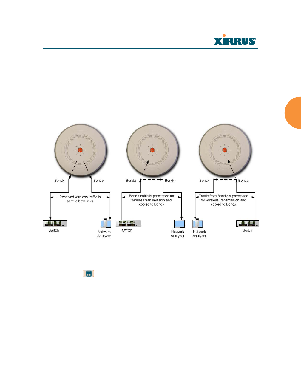
Wireless Array
received on Bondx is passed on to the onboard processor as well as out
Bondy. All traffic received on Bondy is passed on to the onboard
processor as well as out Bondx. This allows a network analyzer to be
plugged into Bondy to capture traffic for troubleshooting, while the
bonded ports provide network connectivity for data traffic.
If each bond contains just one port, then you have the simple case of one
port mirroring another.
Figure 103. Mirroring Traffic
7. When done configuring bonds and bridging as desired, click the Save
button if you wish to make your changes permanent.
See Also
Network Interfaces
DNS Settings
Network
Network Statistics
Spanning Tree Status
Configuring the Wireless Array 175

Wireless Array
DNS Settings
This window allows you to establish your DNS (Domain Name System) settings.
The Array uses these DNS servers to resolve host names into IP addresses. The
Array also registers its own Host Name with these DNS servers, so that others
may address the Array using its name rather than its IP address. An option allows
you to specify that the Array’s DNS servers will be assigned via a DHCP server
on the wired network.
Note that the DNS servers defined here are not used by wireless clients — servers
for stations associated to the Array are defined along with DHCP pools. See
“DHCP Server” on page 194. At least one DNS server must be set up if you want
to offer clients associating with the Array the ability to use meaningful host
names instead of numerical IP addresses. When finished, click the Save button
if you wish to make your changes permanent.
Figure 104. DNS Settings
Procedure for Configuring DNS Servers
1. DNS Host Name: Enter a valid DNS host name.
2. DNS Domain: Enter the DNS domain name.
3. DNS Server 1: Enter the IP address of the primary DNS server.
4. DNS Server 2 and DNS Server 3: Enter the IP address of the secondary
and tertiary DNS servers (if required).
5. Use DNS settings assigned by DHCP: If you are using DHCP to assign
the Array’s IP address, you may turn this option On. The Array will then
obtain its DNS domain and server settings from the network DHCP
176 Configuring the Wireless Array

Wireless Array
server that assigns an IP address to the Array, rather than using the DNS
Server fields above. You may also configure that DHCP server to assign a
host name to the Array.
6. Click the Save button if you wish to make your changes permanent.
See Also
DHCP Server
Network
Network Interfaces
Network Statistics
Spanning Tree Status
CDP Settings
CDP (Cisco Discovery Protocol) is a layer 2 network protocol used to share
information (such as the device manufacturer and model, network capabilities,
and IP address) with other directly connected network devices. Wireless Arrays
can both advertise their presence by sending CDP announcements, and gather
and display information sent by neighbors (see “CDP Neighbors” on page 108).
This window allows you to establish your CDP settings. When finished, the Save
button if you wish to make your changes permanent.
Figure 105. CDP Settings
Procedure for Configuring CDP Settings
1. Enable CDP: When CDP is enabled, the Array sends out CDP
announcements of the Array’s presence, and gathers CDP data sent by
neighbors. When disabled, it does neither. CDP is enabled by default.
Configuring the Wireless Array 177

Wireless Array
2. CDP Interval: The Array sends out CDP announcements advertising its
presence at this interval. The default is 60 seconds.
3. CDP Hold Time: CDP information received from neighbors is retained
for this period of time before aging out of the Array’s neighbor list. Thus,
if a neighbor stops sending announcements, it will no longer appear on
the CDP Neighbors window after CDP Hold Time seconds from its last
announcement. The default is 180 seconds.
See Also
CDP Neighbors
Network
Network Interfaces
Network Statistics
178 Configuring the Wireless Array
Wireless Array
Services
This is a status-only window that allows you to review the current settings and
status for services on the Array, including DHCP, SNMP, Syslog, and Network
Time Protocol (NTP) services. For example, for the DHCP server, it shows each
DHCP pool name, whether the pool is enabled, the IP address range, the gateway
address, lease times, and the DNS domain being used. There are no configuration
options available in this window, but if you are experiencing issues with network
services, you may want to print this window for your records.
Figure 106. Services
The following sections discuss configuring services on the Array:
“Time Settings (NTP)” on page 180
“NetFlow” on page 182
“Wi-Fi Tag” on page 183
“Location” on page 184
“System Log” on page 186
“SNMP” on page 191
Configuring the Wireless Array 179
Wireless Array
“DHCP Server” on page 194
“Proxy Forwarding” on page 196
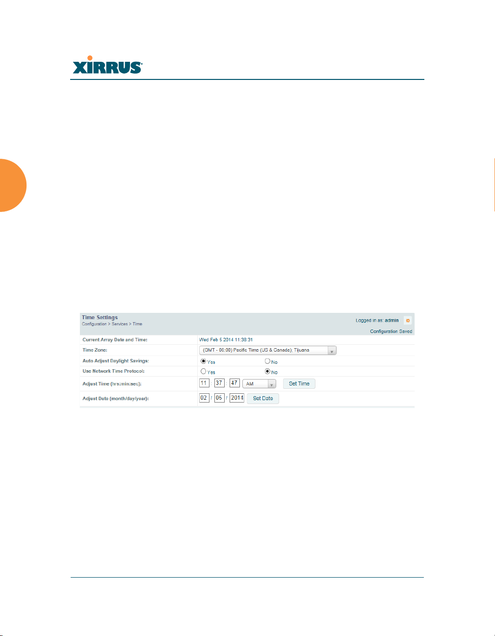
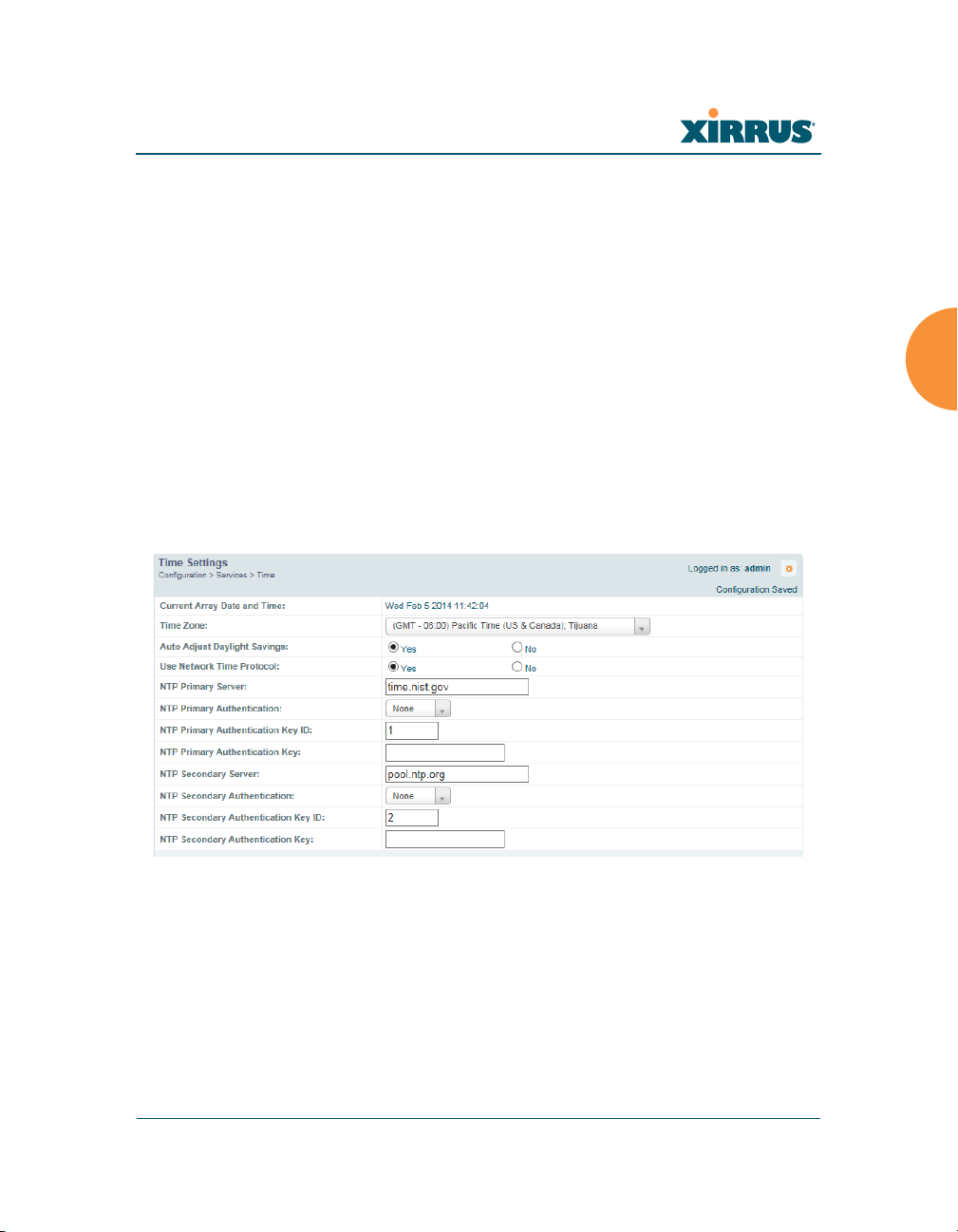
Time Settings (NTP)
This window allows you to manage the Array’s time settings, including
synchronizing the Array’s clock with a universal clock from an NTP (Network
Time Protocol) server. We recommend that you use NTP for proper operation of
SNMP in XMS (the Xirrus Management System), since a lack of synchronization
will cause errors to be detected. Synchronizing the Array’s clock with an NTP
server also ensures that Syslog time-stamping is maintained across all units.
It is possible to use authentication with NTP to ensure that you are receiving
synchronization from a known source. For example, the instructions for
requesting a key for the NIST Authenticated NTP server are available at
http://www.nist.gov/pml/div688/grp00/upload/ntp_instructions.pdf.
The Array allows you to enter optional authentication information.
Figure 107. Time Settings (Manual Time)
Procedure for Managing the Time Settings
1. Current Array Date and Time: Shows the current time.
2. Time Zone: Select the time zone you want to use (normally your local
time zone) from the pull-down list.
3. Auto Adjust Daylight Savings: Check this box to have the system adjust
for daylight savings automatically, else leave it unchecked (default).
4. Use Network Time Protocol: select whether to set time manually or use
NTP to manage system time.
180 Configuring the Wireless Array
Wireless Array
5. Setting Time Manually
a. Adjust Time (hrs:min:sec): If you are not using NTP, use this field if
you want to adjust the current system time. Enter a revised time
(hours, minutes, seconds, am/pm) in the corresponding fields. Click
Set Time to apply the changes.
b. Adjust Date (month/day/year): If you are not using NTP, use this
field if you want to adjust the current system date. Enter a revised
date (month, day and year) in the corresponding fields. Click Set
Date to apply the changes.
6. Using an NTP Server
a. NTP Primary Server: If you are using NTP, enter the IP address or
domain name of the NTP server.
Figure 108. Time Settings (NTP Time Enabled)
b. NTP Primary Authentication: (optional) If you are using
authentication with NTP, select the type of key: MD5 or SHA1. Select
None if you are not using authentication (this is the default).
c. NTP Primary Authentication Key ID: Enter the key ID, which is a
decimal integer.
Configuring the Wireless Array 181
Wireless Array
d. NTP Primary Authentication Key: Enter your key, which is a string
of characters.
e. NTP Secondary Server: Enter the IP address or domain name of an
optional secondary NTP server to be used in case the Array is unable
to contact the primary server. You may use the authentication fields
as described above if you wish to set up authentication for the
secondary server.
See Also
Express Setup
Services
SNMP
System Log
NetFlow
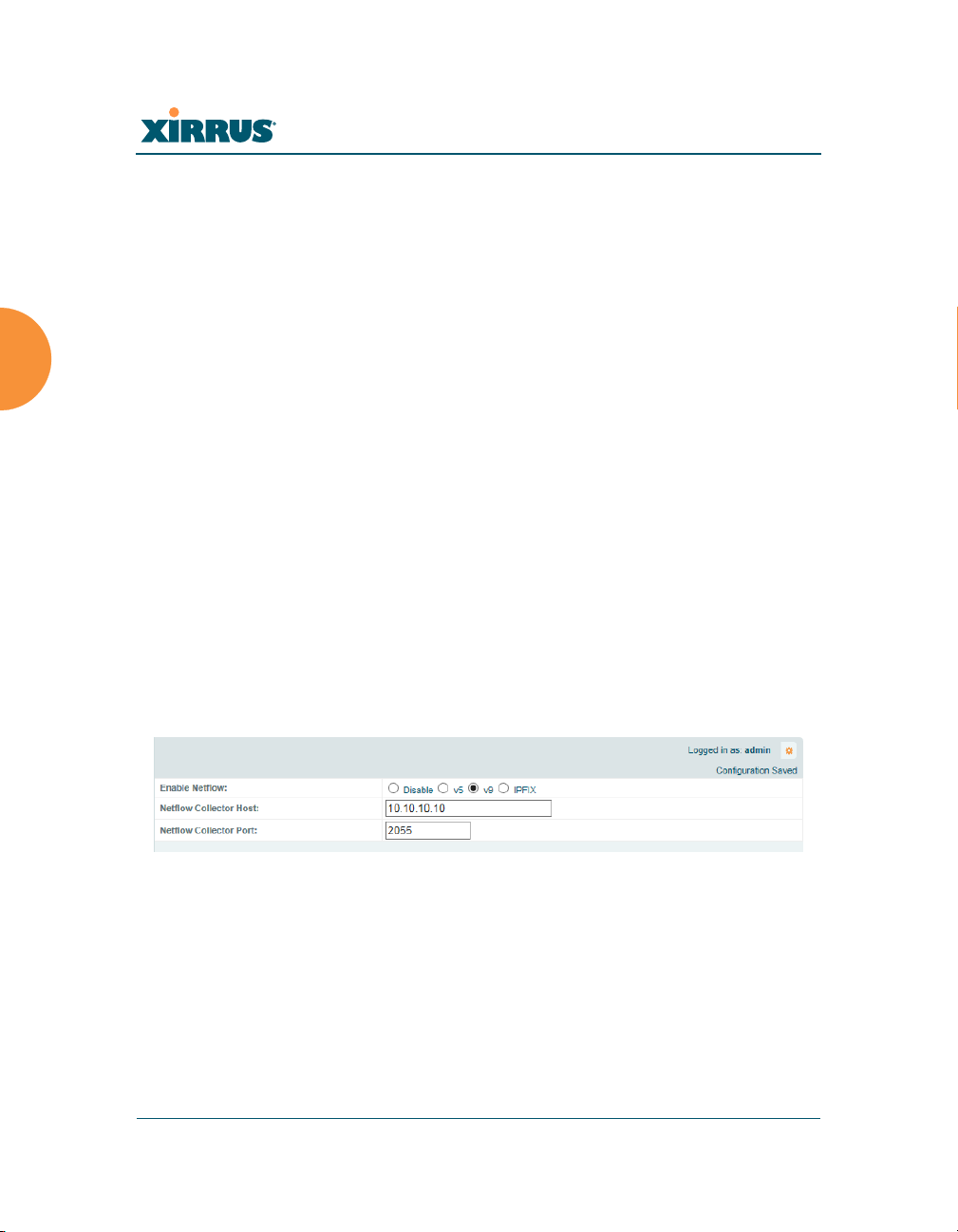
This window allows you to enable or disable the sending of NetFlow information
to a designated collector. NetFlow is a proprietary but open network protocol
developed by Cisco Systems for collecting IP traffic information. When NetFlow
is enabled, the Array will send IP flow information (traffic statistics) to the
designated collector.
Figure 109. NetFlow
NetFlow sends per-flow network traffic information from the Array. Network
managers can use a NetFlow collector to view the statistics on a per-flow basis
and use this information to make key decisions. Knowing how many packets and
bytes are sent to and from certain IP addresses or across specific network
interfaces allows administrators to track usage by various areas. Traffic flow
information may be used to engineer networks for better performance.
182 Configuring the Wireless Array
Wireless Array
Procedure for Configuring NetFlow
1. Enable NetFlow: Select one of the Netflow versions to enable NetFlow
functionality: v5, v9, or IPFIX. Internet Protocol Flow Information Export
(IPFIX) is an IETF protocol (www.ietf.org) performing many of the same
functions as Netflow. Choose Disable if you wish to disable this feature.
2. NetFlow Collector Host (Domain or IP): If you enabled NetFlow, enter
the domain name or IP address of the collector.
3. NetFlow Collector Port: If you enabled NetFlow, enter the port on the
collector host to which to send data.
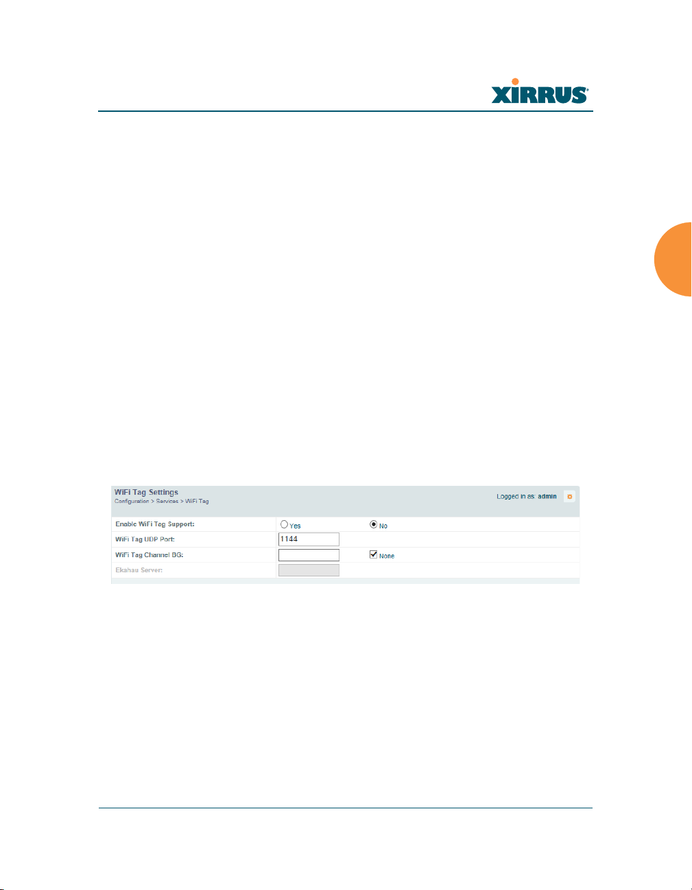
Wi-Fi Tag
This window enables or disables Wi-Fi tag capabilities. When enabled, the Array
listens for and collects information about Wi-Fi RFID tags sent on the designated
channel. These tags are transmitted by specialized tag devices (for example,
AeroScout or Ekahau tags). A Wi-Fi tagging server then queries the Array for a
report on the tags that it has received. The Wi-Fi tagging server uses proprietary
algorithms to determine locations for devices sending tag signals.
Figure 110. Wi-Fi Tag
Procedure for Configuring Wi-Fi Tag
1. Enable Wi-Fi Tag: Choose Yes to enable Wi-Fi tag functionality, or choose
No to disable this feature.
Configuring the Wireless Array 183

Wireless Array
2. Wi-Fi Tag UDP Port: If Wi-Fi tagging is enabled, enter the UDP port that
the Wi-Fi tagging server will use to query the Array for data. When
queried, the Array will send back information on tags it has observed. For
each, the Array sends information such as the MAC address of the tag
transmitting device, and the RSSI and noise floor observed.
3. Wi-Fi Tag Channel BG: If you enabled Wi-Fi tagging, enter the 802.11
channel on which the Array will listen for tags. The tag devices must be
set up to transmit on this channel. Only one channel may be configured,
and it must be an 802.11b/g channel in the range of Channel 1 to 11.
4. Ekahau Server: If you enabled Wi-Fi tagging and you are using an
Ekahau server, enter its IP address or hostname. Ekahau Wi-Fi Tag
packets received by the Array will be encapsulated as expected by
Ekahau, and forwarded to the server.
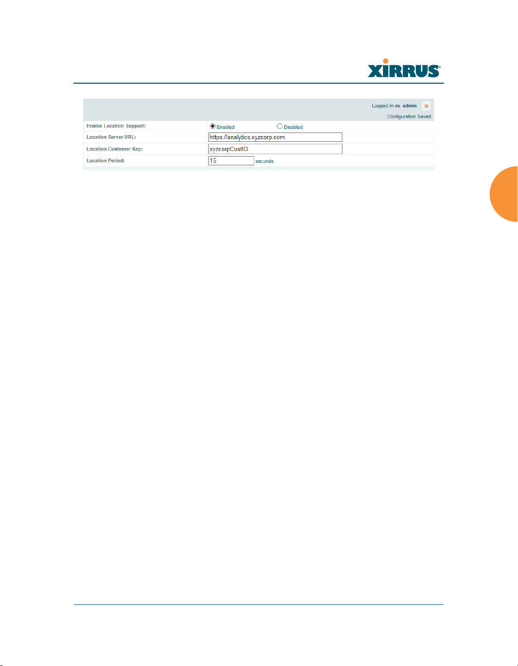
Location
The Array offers an integrated capability for capturing and uploading visitor
analytics data, eliminating the need to install a standalone sensor network. This
data can be used to characterize information such as guest or customer traffic and
location, visit duration, and frequency. Use this Location window to configure the
Array to send collected data to an analytics server, such as Euclid.
When Location Support is enabled, the Array collects information about stations,
including the station ID and manufacturer, time and length of the visit and related
time interval statistics, and signal strength and its related statistics. Data collected
from stations comprises only basic device information that is broadcast by Wi-Fi
enabled devices. Devices that are only detected are included, as well as those that
actually connect to the Array. The Array sending the data also sends its own ID so
that the server knows where the visitors were detected. Data messages are
uploaded via HTTPS, and they are encrypted if a Location Customer Key has
been entered. Data is sent as JSON (JavaScript Object Notation) objects, as
described in “Location Service Data Formats” on page 504.
184 Configuring the Wireless Array
Wireless Array
Figure 111. Location
Procedure for Configuring Location
1. Enable Location Support: Choose Yes to enable the collection and upload
of visitor analytic data, or choose No to disable this feature.
2. Location URL: If Location Support is enabled, enter the IP address or
hostname of the location/analytics server. If this URL contains the string
euclid, then the Array knows that data is destined for a Euclid location
server.
For a Euclid analytics server, use the URL that was assigned to you as a
customer by Euclid. The Array will send JSON-formatted messages in the
form required by Euclid via HTTPS.
For any other location analytics server, enter its URL. The Array will send
JSON-formatted messages in the form described in “Location Service
Data Formats” on page 504.
3. Location Customer Key: (optional) If a Location Customer Key has been
entered, data is sent encrypted using AES with that key.
4. Location Period: If you enabled Location Support, specify how often data
is to be sent to the server, in seconds.
Configuring the Wireless Array 185
Wireless Array
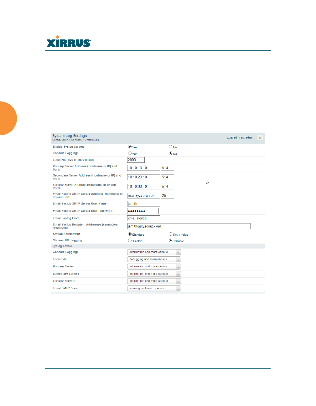
System Log
This window allows you to enable or disable the Syslog server, define primary,
secondary, and tertiary servers, set up email notification, and set the level for
Syslog reporting for each server and for email notification — the Syslog service
will send Syslog messages at the selected severity or above to the defined Syslog
servers and email address. An option allows you to use a Splunk application to
analyze Array events by sending data in key:value pairs, as described in “About
Using the Splunk Application for Xirrus Arrays” on page 189.
Figure 112. System Log
Procedure for Configuring Syslog
1. Enable Syslog Server: Choose Yes to enable Syslog functionality, or
choose No to disable this feature.
186 Configuring the Wireless Array
 Loading...