

Cambium Networks XDR241 Users Manual
XA4 Series High Density Access Points
1
Quick Installation Guide
For XA4 Models
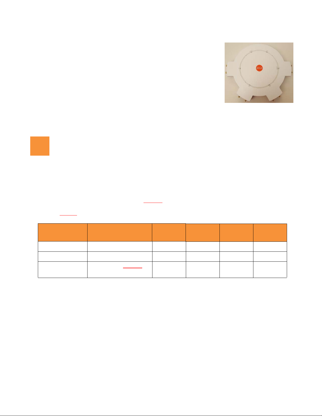
XA4 Series High Density Convention Center Access Points (CCAPs) are plenumrated indoor APs using external antennas. With four 802.11ac Wave 2 radios, a
powerful integrated controller, application-level intelligence, automated
provisioning, and optional cloud management, the APs deliver robust wireless
connectivity in areas of medium to high user density. The XA4-240 has four 4x4
Wave 2 802.11ac radios: Radio IAP1 is a dual-band 2.4GHz/5GHz radio, and
IAP2 through IAP4 are single-band 5GHz radios.
This Guide covers the steps required to install and start the AP. For detailed configuration information, see the
Xirrus Wireless Access Point User's Guide.
You Need the Following Items
Accessory Kit (included in each AP carton) includes Mounting bracket
Xirrus-recommended antennas (and cables if needed) for up to four radios. Network designers should specify
how many antennas to install for each radio. See the table below and “Install Antennas” on page 3 to see what
connectors to use, based on the number of antennas allocated to a radio. Cables (if needed) are low-loss coaxial
cables terminated with RP-SMA connectors. ??OK??
output power setting must be reduced by 1 dB for every dB above 6dBi gain the selected antenna may
produce. ??OK??
If you are not using recommended antennas, the XA4’s
# Antenna
Connectors to Use
22x2YesNoNoYes
3 3x3; or 2x2 plus DFS* Yes Yes No Yes
4 4x4 (default ??OK??
DFS*: Zero-wait DFS (dynamic frequency selection) uses a dedicated antenna to provide fast frequency
selection. This enables better use of 5GHz Wi-Fi channels.
... For Usage Scenario
(Configured settings)
or 3x3 plus DFS*
Connector 1 Connector 2 Connector 3 Connector 4
);
Yes Yes Yes Yes
Power and Ethernet connection(s) to your wired network using Cat 5e/6 cables. The AP has 2 Ethernet ports:
GIG1/PoE—This 2.5 Gigabit port powers the AP via Power over Ethernet (PoE) using a Cat 5e or Cat 6
cable that also carries data traffic. See below for Power details. Note that the port’s rate is set by autonegotiation with the switch.
(Optional) GIG2—Connection to this second, data-only one-gigabit port provides additional bandwidth.
Use Cat 5E or Cat 6 cable.
AP must be connected to PoE networks without routing cabling to the outside plant. This ensures that cabling is
not exposed to lightning strikes or possible crossover from high voltage lines. AP, PoE Injectors, or Switches must
be installed and used indoors. The total Cat 5e or Cat 6 cable length from the switch to the AP must be no more
than 100 m, including all cable segments.
1
XA4 Series High Density Access Points
2
Power— See the matrix below to select a compatible PoE switch or Xirrus-supplied injector for your AP. If
using an injector, you must provide a data connection from the switch to the injector as well as another cable
from the injector's OUT port to the AP’s GIGABIT1/PoE port. PoE injectors require an AC outlet.
(POE-75U-1UP-X)
XP1-MSI-75
XP8-MSI-70M
XP2-MSI-95M
AP Model
Consumption
Maximum
Power
PoE Switch
(802.3at)
Generic
PoE Switch
Xirrus
XP1-MSI-30
XP1-MSI-75M
XA4-240 38W
(Ports
1-12 only)
Apply power to GIG1/POE port only—other AP Gigabit ports will not draw power if connected to a
powered switch port, and AP LEDs will not light.
Workstation with a Web browser to configure the AP via the Xirrus Management System or directly via the
AP’s Windows Management Interface (WMI).
NOTE: Leave protective plastic film on the AP until installation is complete, to avoid leaving marks on the AP.
Direct Ceiling Mount—use the furnished mounting plate with four user-supplied screws that are appropriate
for the construction type of the mounting site. The AP attaches to the mounting plate with four keyhole studs
that are pre-installed on the back of the AP.
Choose a Suitable Location
Choose an indoor location that is central to your users, and that is away from heat sources.
The location must be capable of supporting the weight of the AP and the mounting bracket (about 5?? lb total).
For optimal placement, we recommend that a predictive survey be performed by a qualified Xirrus partner.
Maintain a distance of at least 50 feet between additional APs.
Keep the unit away from electrical devices or appliances that generate RF noise-at least 3 to 6 ft (1m - 2m).
To ensure good air flow, it is essential that the AP’s vents are not blocked.
The XA4 can operate from a Wireless Distribution System (WDS) link. However, the unit must be configured
via the Ethernet connection prior to mounting and power must be supplied via the GIG1 Ethernet connector.
2
XA4 Series High Density Access Points
3
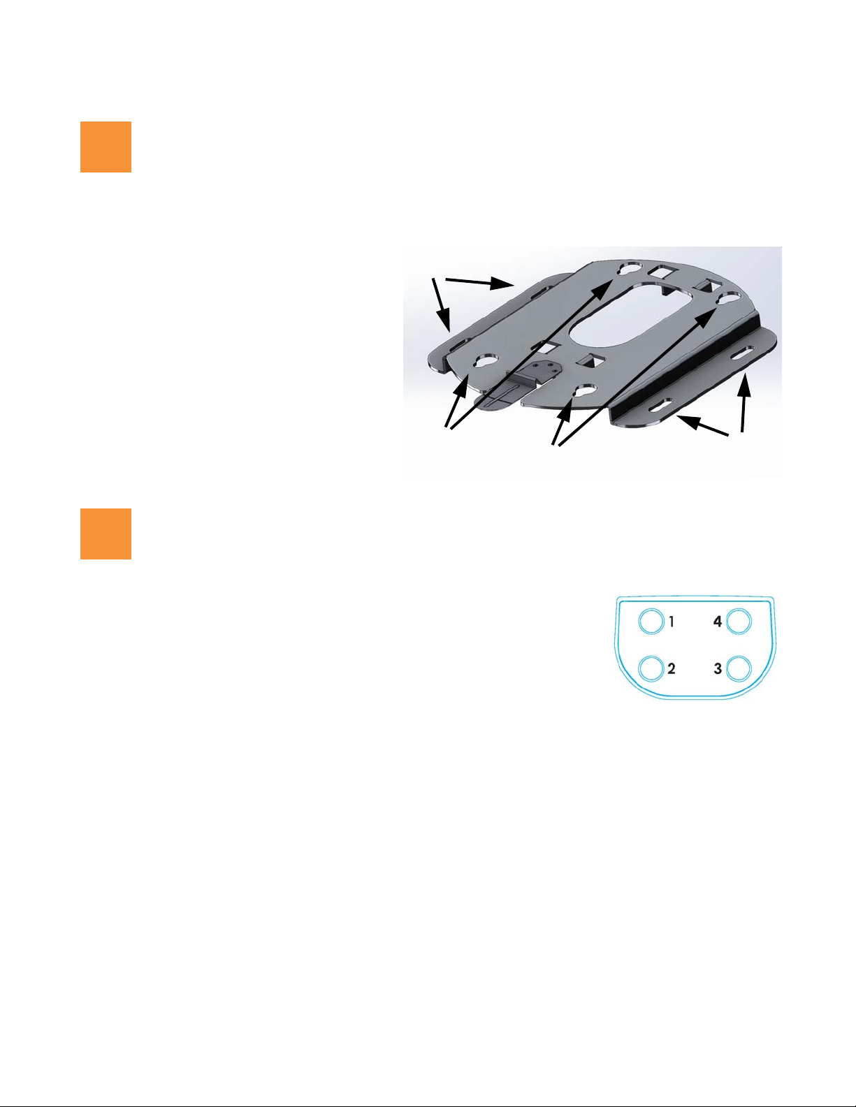
Mounting slots
AP attachment
keyhole slots
Mounting slots
Cable
feed
4
Antenna Connectors
Install Mounting Hardware—Ceiling Mount
The following steps use a mounting plate, which offers a secure mount and ease of dismount.
1. Use the AP mounting plate to mark the
placement on the ceiling of the cable feed
opening and of the 4 mounting slots.
2. Drill and prepare holes for user-supplied
screws as appropriate.
3. Cut an access hole for the cable(s) in the
ceiling and draw enough cable through to
attach to the AP when it is installed.
4. Align the mounting plate over the prepared
holes (position the edges with the mounting
slots flush against the wall.). Feed the cable(s)
through. Secure the plate with the screws.
Install Antennas
See the Xirrus External Antenna Guide for recommended antennas.
Check the network plan for the number of antennas to connect to each of the
four radios, named IAP1 to IAP4. The table on page 1 shows which
connector numbers to use, and the image at right shows their numbering.
For Rubber Duck Antennas:
Install the antennas on the AP at the locations described above.
For Panel Antennas:
Install your antenna(s) as directed by the manufacturer. Note that radio IAP1 is dual-band, so if you use single-
band antennas for it, you must configure IAP1 to the antenna’s band (2.4 GHz or 5.0 GHz). See “Zero-Touch
Provisioning and Ongoing Management” on page 4).
Use low-loss coaxial cables compatible with the XA4’s RP-SMA connectors. Note that some antennas include
integrated cables as part of the unit, and these do not need separate cables.
3
XA4 Series High Density Access Points
5
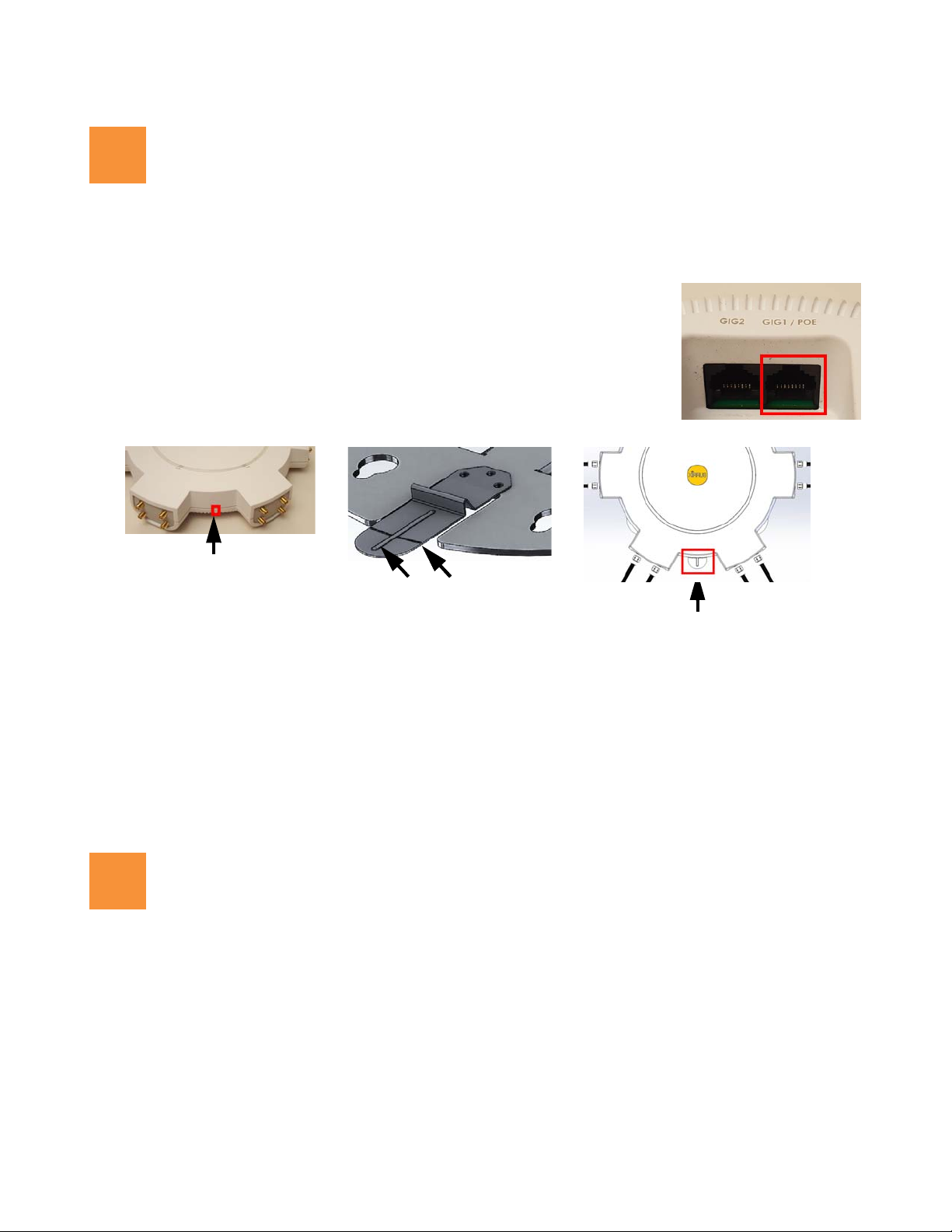
POE
Alignment Lines on
Lock/Unlock Lever
Alignment Line
on AP
Alignment Lines on
Lock/Unlock Lever
Lock/Unlock Lever
Installed AP
6
Connect Cables and Install AP
NOTE: Once you connect GIG1/POE, an automatic upgrade typically starts soon after the AP has Internet connectivity. Do
not unplug this port during the upgrade or the AP may become inoperable. The upgrade should take 10 minutes or less.
1. Connect the cable that carries power and data to GIG1/PoE (shown in red). If you
use a Xirrus-supplied injector, its CONNECT LED should light (for 70W and
higher injectors, it is OK if it blinks). If power is being properly supplied, the AP’s
LEDs will light and then commence blinking in their rotating boot pattern. A
second data connection may be plugged into GIG2 (optional).
2. If using panel antennas, connect the cables as indicated in the table on page 1.
3. Mount the AP: Position the keyhole studs on the back of the AP over the keyhole slots on the mounting plate
using the following aid—line up the alignment line on the AP (small bump located on the AP as indicated
above) with the vertical line on the lock lever.
4. Push the AP against the mounting plate and slide the AP towards the locking lever until the keyhole slugs are
secure in the slots and the lever locks in place. The edge of the AP will line up with the horizontal line on the
lock lever.
5. If you need to remove the AP, push down on the lock lever to unlock the AP. Continue to hold it down while
Zero-Touch Provisioning and Ongoing Management
Most customers use the Xirrus Management System (XMS) for the initial setup and continuing management of
Xirrus APs. XMS users set up new APs for zero-touch provisioning via the following platforms. Wait five minutes
after powering up the AP to automatically discover it, then use XMS to view and manage it. Newly discovered
APs are automatically assigned to the XMS “default” profile, and receive the configuration defined for that profile.
XMS-Cloud—performs zero-touch provisioning. Your new APs appear in XMS even before you receive your
you slide the AP away from the lever and pull the AP off the mounting plate.
equipment. When the email arrives with your login information, use XMS-Cloud to specify the initial settings
for your APs. A Guided Tour will walk you through the basic steps of creating a profile containing
4
1.800.947.7871 Toll Free in the US
+1.805.262.1600 Sales
+1.805.262.1601 Fax
2101 Corporate Center Drive
Thousand Oaks, CA 91320, USA
To learn more visit:
xirrus.com or
email info@xirrus.com
© 201 Xirrus, Inc. All Rights Reserved. The Xirrus logo is a registered trademark of Xirrus, Inc.
All other trademarks are the property of their respective owners. Content subject to change without notice.
configuration settings, including creating SSIDs and firewall/application control rules. Once the installed AP
7
has Internet connectivity, it will automatically contact Xirrus for cloud-based zero-touch provisioning per your
settings, install the latest applicable license, and upgrade the AP to the latest software version as appropriate.
XMS-Enterprise—detects and provisions new Xirrus devices deployed in your network. Create and configure
a default profile for newly added APs, then set up discovery for the APs’ subnetwork. New devices will
automatically receive the configuration defined in the default profile.
If you are not using XMS, please see the Xirrus Wireless AP User's Guide to configure the AP manually via the
Express Setup menu. The User Guide is available from http://support.xirrus.com (login required). Select the
Libraries tab and click the ArrayOS - XR Platform Latest Release link.
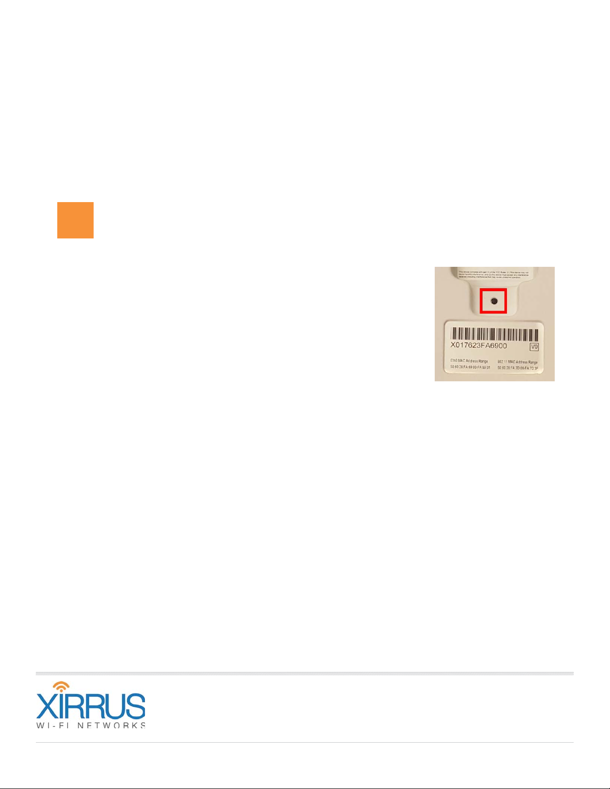
Using the Reset Button
The reset button returns the AP to factory default settings while rebooting. It is
located on the bottom of the AP, just above the serial number/bar code. Use the
reset button as follows:
Unplug the cable from the GIG1/PoE port.
Press the reset button all the way (there should be a faint click) and hold it.
Plug the cable back in and continue to keep the button pressed for 10 seconds.
This triggers the factory default reset during the boot process.
812-0085-013 Rev A

Wireless Access Point
Appendix C: Notices (XA, XD and XR500/
600 Series Only)
This appendix contains the following information:
“Notices” on page 553
“EU Directive 1999/5/EC Compliance Information” on page 562
“Compliance Information (Non-EU)” on page 569
“Safety Warnings” on page 570
“Translated Safety Warnings” on page 571
“Software License and Product Warranty Agreement” on page 572
“Hardware Warranty Agreement” on page 572
This Appendix contains Notices, Warnings, and Compliance information for
the XA, XD and XR500/600 Series only.
For Notices, Warnings, and Compliance information for outdoor products,
please see the Quick Installation Guide for that product.
For Notices, Warnings, and Compliance information for XR-320 and
X2-120, please see the X2 and XR300 Series Notices and Regulatory
Guide.
For Notices, Warnings, and Compliance information for all other APs,
please see “Notices (XR-1000 to XR-6000 Indoor Models)” on page 571.
Notices
Wi-Fi Alliance Certification
www.wi-fi.org
553

Wireless Access Point
FCC Notice for XD4-240 (XD4240)
This equipment has been tested and found to comply with the limits for a Class A
digital device, pursuant to part 15 of the FCC Rules. These limits are designed to
provide reasonable protection against harmful interference when the equipment
is operated in a commercial environment. This equipment generates, uses, and
can radiate radio frequency energy and, if not installed and used in accordance
with the instruction manual, may cause harmful interference to radio
communications. Operation of this equipment in a residential area is likely to
cause harmful interference in which case the user will be required to correct the
interference at his own expense.
FCC Notice for All Other Devices Covered by This Appendix
This equipment has been tested and found to comply with the limits for a Class B
digital device, pursuant to Part 15 of the FCC rules. These limits are designed to
provide reasonable protection against harmful interference in a residential
installation. This equipment generates, uses and can radiate RF energy and, if not
installed and used in accordance with the instructions, may cause harmful
interference to radio communications. However, there is no guarantee that
interference will not occur in a particular installation. If this equipment does
cause harmful interference to radio or television reception, which can be
determined by turning the equipment off and on, the user is encouraged to try to
correct the interference by one or more of the following safety measures:
Reorient or relocate the receiving antenna.
Increase the separation between the equipment and the receiver.
Connect the equipment into an outlet on a circuit different from that to
which the receiver is connected.
Consult the dealer or an experienced wireless technician for help.
For All Devices Covered by This Appendix
The rest of the information in this Appendix applies to all Xirrus XA, XD and
XR500/600 Series APs, except as noted.
554

Wireless Access Point
FCC Caution: Any changes or modifications not expressly approved by the
!
party responsible for compliance could void the user's authority to operate this
equipment.
This device complies with Part 15 of the FCC Rules, with operation subject to the
following two conditions: (1) This device may not cause harmful interference, and
(2) this device must accept any interference received, including interference that
may cause unwanted operation.
For all models available in the USA/Canada market, only channels 1~11 can be
operated in the 2.4GHz band. Selection of other channels is not possible.
This device and its antenna(s) must not be co-located or operating in conjunction
with any other antenna or transmitter except in accordance with FCC multi-
transmitter product procedures.
This device is restricted for indoor use.
Operations in the 5.15-5.25GHz band are restricted to indoor usage only.
IMPORTANT NOTE: FCC Radiation Exposure Statement
This equipment complies with FCC radiation exposure limits set forth for an
uncontrolled environment. To ensure compliance with FCC and Industry Canada
RF exposure requirements, this device must be installed in a location where the
antennas of the device will have a minimum distance of at least 30 cm (12 inches)
from all persons, except that XD2 models must have a minimum distance of at
least 20 cm (8 inches) from all persons, and the antennas of XA4 models must
have a minimum distance of at least 34 cm (13.6 inches) from all persons. Using
higher gain antennas and types of antennas not certified for use with this product
is not allowed. The device shall not be co-located with another transmitter.
High Power Radars
High power radars are allocated as primary users (meaning they have priority) in
the 5250MHz to 5350MHz and 5650MHz to 5850MHz bands. These radars could
cause interference and/or damage to LE-LAN devices.
555
 Loading...