

Cambium Networks XD2240B Users Manual

Wireless Access Point
X2 and XD2 Series
Quick Installation Guide
XD4 Series
August 8, 2015

is a registered trademark of Xirrus, Inc. All other trademarks and brand names are marks of their respective
holders.
Please see Legal Notices, Warnings, Compliance Statements, and Warranty and License Agreements in the Xirrus
Wireless AP User’s Guide.
All rights reserved. This document may not be reproduced or disclosed in whole or in part by any means without
the written consent of Xirrus, Inc.
Part Number: 812-0085-012 Rev A August 8, 2015
X2 and XD2 Two-Radio Access Points
1
Quick Installation Guide
For X2 and XD2 Series Models
X2 and XD2 Series Access Points (APs) are new classes of APs within the Xirrus wireless
portfolio. With two omnidirectional 802.11ac radios, a powerful integrated controller,
application-level intelligence, and optional cloud management, the APs deliver robust
wireless connectivity in areas of medium to high user density. The XD2-240 AP has two
802.11ac Wave 2 radios, while the X2-120 has two Wave 1 radios.
The X2 Series includes the X2-120 (Model X2120). The XD2 Series includes the XD2-240 (Model XD2240).
This Guide covers the steps required to install and start these APs. For detailed configuration information, see the
Xirrus Wireless AP User's Guide.
You Need the Following Items
Power and Ethernet connection(s) to your wired network using Cat 5e or Cat 6 cables:
GIG1/POE—This Gigabit port powers the AP via Power over Ethernet (PoE) using a Cat 5e or Cat 6 cable
that also carries data traffic. See below for Power details.
GIG2—This second, data-only Gigabit port is only available on the XD2, and provides additional
bandwidth. Its use is optional. Connect with Cat 5E or Cat 6 cable.
AP must be connected to PoE networks without routing cabling to the outside plant. This ensures that cabling is
not exposed to lightning strikes or possible crossover from high voltage lines. AP, PoE Injectors, and Switches
must be installed and used indoors. The total Cat 5e or Cat 6 cable length from the switch to the AP must be no
more than 100 m, including all cable segments.
Power— See the matrix below to select a compatible PoE switch or Xirrus-supplied injector for your AP.
X2 models are IEEE802.3af-compatible, while XD2 models require 802.3at. If using an injector, you must
provide a data connection from the switch to the injector as well as another cable from the injector's OUT port
to the AP’s GIG1/POE port.
Injector or Switch
Generic PoE+
(802.3at)
PoE+ Switch
(802.3at)
Xirrus
XP1-MSI-20
XP1-MSI-30
XP1-MSI-75M
(POE-75U-1UP-X)
XP1-MSI-75
XP8-MSI-70M
XP2-MSI-95M
AP Type
X2
XD2
Injector or Switch
Generic PoE
(802.3af)
Apply power to GIG1/POE port only—other AP Gigabit ports will not draw power if connected to a
powered switch port, and AP LEDs will not light.
If you are using a POE switch, it is imperative that you know that the switch has sufficient power budget
to power all connected devices.
1
X2 and XD2 Two-Radio Access Points
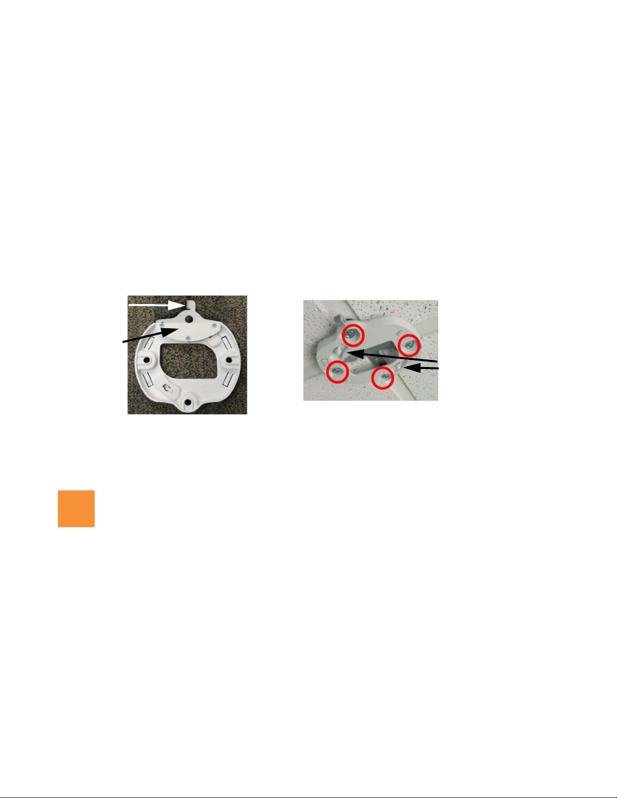
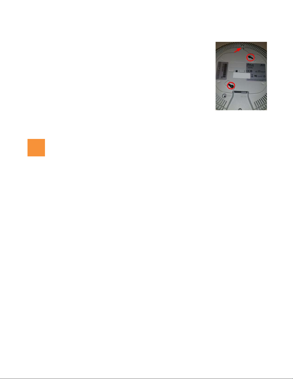
Locking
Ta b
Locking
Plate
Recessed mounting
holes (circled in red,
only 2 ceiling clips
needed)
Tabs for
attaching AP
2
All Xirrus XD2 APs are Type 2, Class 4 POE-802.3at devices. If your switch vendor provides a setting for
the type of powered-device detection with options such as Legacy, 4-Point, or BOTH, set the port to BOTH
or 4-Point. Do not use settings intended for legacy devices.
Access to a Web browser to configure the AP via the Xirrus Management System or directly via the AP’s
Windows Management Interface (WMI).
For a suspended ceiling mount, you need a 7/16” nut driver to attach the mounting plate to the T-Bar clips.
(See “Install Mounting Hardware and AP” on page 3.) Do not use old T-bar clips or studs from XN or XS APs
with the X2 and XD2 Series—they will damage the AP case.
For a locked installation, supply a zip-tie, small lock, or other locking hardware.
NOTE: Leave protective plastic film on the AP until installation is complete, to avoid leaving marks on the AP.
Mounting Options
Direct Ceiling Mount—for the ability to lock the AP in place or detect tampering, use the furnished mounting
plate with at least two user-supplied screws.
AP Mounting Plate (back) AP Mounting Plate (front, mounted)
Suspended Ceiling Grid Mount—See photos above and on page 3. Use the mounting plate with the two
supplied T-Bar clips (for 15/16” ceiling grid). For a slotted ceiling grid, T-slot bolts are available for attaching
the mounting plate to slots in the grid.
Wall Mount—use a Wall Mount Kit (XE-500-WALL), which contains a mounting plate, wall mount bracket,
and three screws (1/4” Plastite).
Choose a Suitable Location
Choose an indoor location that is central to your users, that is away from heat sources. To ensure good air flow,
it is essential that the AP’s vents are not blocked.
The AP should be installed parallel to the ground (i.e., in a horizontal position, not tilted on its side). The AP
should not be more than 30 feet above the ground (or the level at which receiving devices will be used). For
atypical installations, please verify the resulting signal coverage.
The location must be capable of supporting the weight of the AP and the mounting bracket (about 2 lb total).
For optimal placement, we recommend that a predictive survey be performed by a qualified Xirrus partner.
Maintain a distance of at least 50 feet between additional APs.
Keep the unit away from electrical devices or appliances that generate RF noise-at least 3 to 6 ft (1m - 2m).
2
X2 and XD2 Two-Radio Access Points
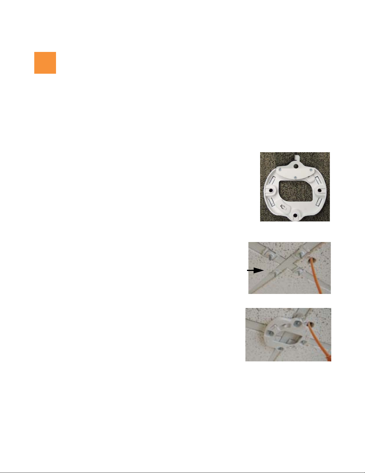
3
T-Bar Clips
(4 shown; only
2 needed)
Install Mounting Hardware and AP
3A—Ceiling Mount with Mounting Plate
3C—Wall Mount with Bracket
3B—Ceiling Grid Mount with Mounting Plate
3A—Ceiling Mount with Mounting Plate
The following steps use a mounting plate, which offers a more secure mount, ease of dismount, and a locking
option for the AP.
1. Use the holes on the AP mounting plate to mark the placement of at least two
user-supplied screws to install in the ceiling.
2. Drill and prepare holes for the screws as appropriate.
3. Cut an access hole for the cable(s) in the ceiling and draw enough cable through
to attach to the AP after it is installed.
4. Align the AP mounting plate over the prepared holes, with the metal locking
plate against the ceiling. Secure the plate with the screws. Do not over-tighten.
5. Proceed to “Connect Cables and Install AP” on page 4.
3B—Ceiling Grid Mount with Mounting Plate
1. For T-Bar clips, use two of the four holes on the AP
mounting plate to mark the placement of two T-bar clips
on the metal ceiling support grid.
2. Cut an access hole in the ceiling tile and draw the cable(s) through.
3. Align the AP mounting plate over the screw posts of the T-Bar bracket or
4. Proceed to “Connect Cables and Install AP” on page 4.
Twist the two supplied T-bar clips onto the metal ceiling
grid at the marked locations and tighten the screw posts
to 10-12 lbf.ft (1.38-1.66 kgf.m). Do not over- tighten the
screw posts.
clips and secure it to the two posts using the nuts provided. Tighten the
nuts to 10-12 lbf.ft (1.38-1.66 kgf.m), but do not over tighten.
3
X2 and XD2 Two-Radio Access Points
4
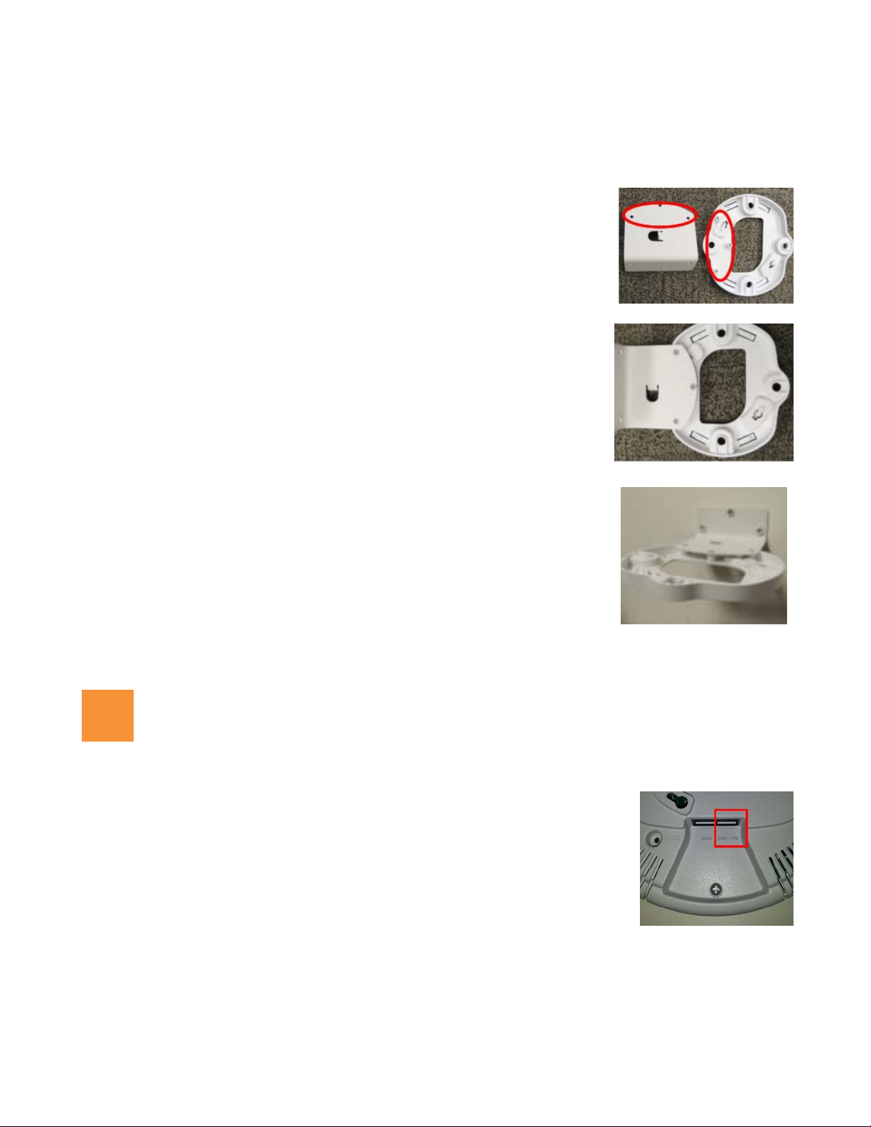
3C—Wall Mount with Bracket
NOTE: The mounting location must be able to support the weight of the AP and the mounting bracket (about 2 lb. total).
1. If the AP mounting plate has a metal locking plate, remove it. Align the three
holes in the wall bracket over the corresponding mounting plate holes. The
wall bracket’s small locking tab should point down toward the mounting plate.
NOTE: Use only the screws provided in the accessory kit. Other screws that seem
equivalent in size may damage the mounting plate.
2. Use the three screws provided in the accessory kit to attach the wall mount
bracket to the AP mounting plate as shown here.
3. Use the Wall Mounting Bracket as a template and mark the locations on the
wall for the mounting holes. The bracket must be secured to the wall in 3
places. When marking the holes, make sure the mounting plate is level.
4. Attach the mounting plate to the wall with three user-supplied screws
appropriate to the wall construction type.
NOTE: The mounting location must be capable of supporting the weight of the AP and the
mounting bracket (about 2 pounds total).
5. Cut an access hole for the cable(s) in the wall and draw enough cable through
to attach to the AP after it is installed.
6. Proceed to “Connect Cables and Install AP” on page 4.
Connect Cables and Install AP
1. Connect the cable that carries power and data to GIG1/POE (shown in red). If
you use a Xirrus-supplied injector, its CONNECT LED should light (for 70W and
higher injectors, it is OK if it blinks). If power is being properly supplied, the
AP’s LEDs will light and then commence blinking in their rotating boot pattern.
A second data connection may be plugged into GIG2 (optional, XD2 only).
4
X2 and XD2 Two-Radio Access Points
5
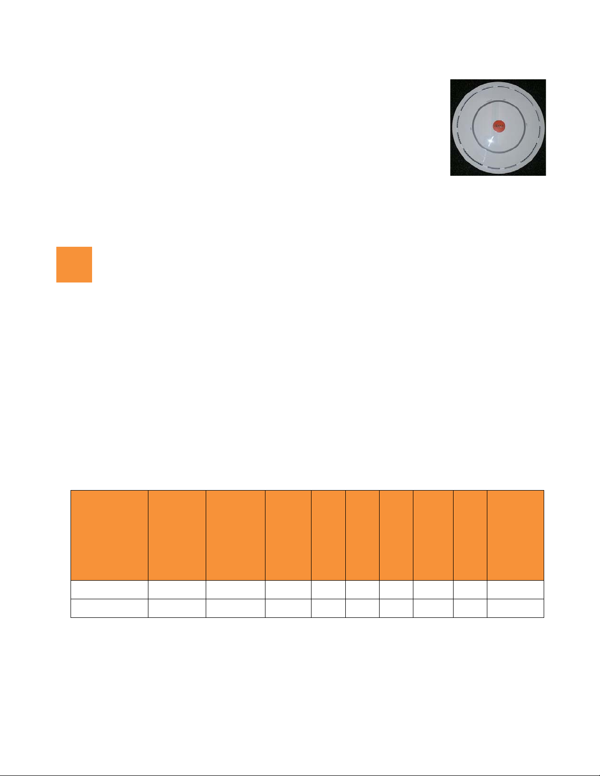
2. Align the two slots on the back of the AP chassis (circled in red) with the
corresponding tabs on the AP mounting plate. To assist you in positioning the
AP, make sure that the AP’s locking slug (red arrow) lines up with the matching
locking tab on the wall bracket or mounting plate (see photos in “AP Mounting
Plate (back)” on page 2).
3. Push the AP chassis up on the mounting plate tabs and rotate the AP to the right
until it snaps in place.
4. To secure the AP to the mounting plate for tamper evidence or to deter removal,
feed a customer-provided zip tie or other locking hardware through the hole in
the top of the locking slug (red arrow, photo above) and the matching locking
tab on the mounting plate or wall bracket.
5. Remove the protective plastic film from the unit.
6. You may remove the AP by pushing it up against the mounting plate and rotating to the left.
Zero-Touch Provisioning and Ongoing Management
Most customers employ the Xirrus Management System (XMS) for the initial setup and continuing management of
Xirrus devices. XMS users can readily set up their new devices for provisioning and ongoing maintenance via the
following platforms. Newly discovered APs are automatically assigned to the XMS “default” profile, and will
receive the configuration defined for that profile.
XMS-Cloud—performs zero-touch provisioning as shown in this quick video guide: http://www.xirrus.com/
TV/Training/XMS-cloud-Next-Generation
equipment. When the email arrives with your login information, use XMS-Cloud to specify the initial settings
for your APs. A Guided Tour will walk you through the basic steps of creating a profile containing
configuration settings, including creating SSIDs and firewall/application control rules. Once the installed AP
has Internet connectivity, it will automatically contact Xirrus for cloud-based zero-touch provisioning per your
settings, install the latest applicable license, and upgrade the AP to the latest software version as appropriate.
XMS-Enterprise—automatically detects and provisions new Xirrus devices deployed in your network via a
similar provisioning approach. Set up discovery for your APs’ subnetwork, and create and configure a default
profile for newly added APs. After discovery, these new devices automatically receive the configuration
defined in your default profile.
If you are not using XMS, please see the Xirrus Wireless AP User's Guide to configure your AP manually (XD2 only)
via the Express Setup menu option. The User Guide is available from
Select the Libraries tab and click the ArrayOS - XR Platform Latest Release link.
. Your new APs appear in XMS even before you receive your
http://support.xirrus.com (login required).
5

X2 and XD2 Two-Radio Access Points
6
7
Using the Reset Button
The reset button returns the AP to factory default settings while rebooting. It is
located on the bottom of the unit. Use the reset button as follows:
Unplug the cable from the GIG1/POE port.
Press the reset button all the way (there should be a faint click) and hold it.
Plug the cable back in and continue to keep the button pressed for 10 seconds.
This triggers the factory default reset during the boot process.
Specifications and Drawings
Physical/Environmental Specifications
Dimensions (WxDxH, including mounting plate): 8 x 8 x 2.25 in / 20.3 x 20.3 x 5.7 cm
Weight: 2 lb / 0.9 kg
Operating Temperature: 0-50°C / 32-122°F, 5-95% humidity, non-condensing.
Mounting Plate
6
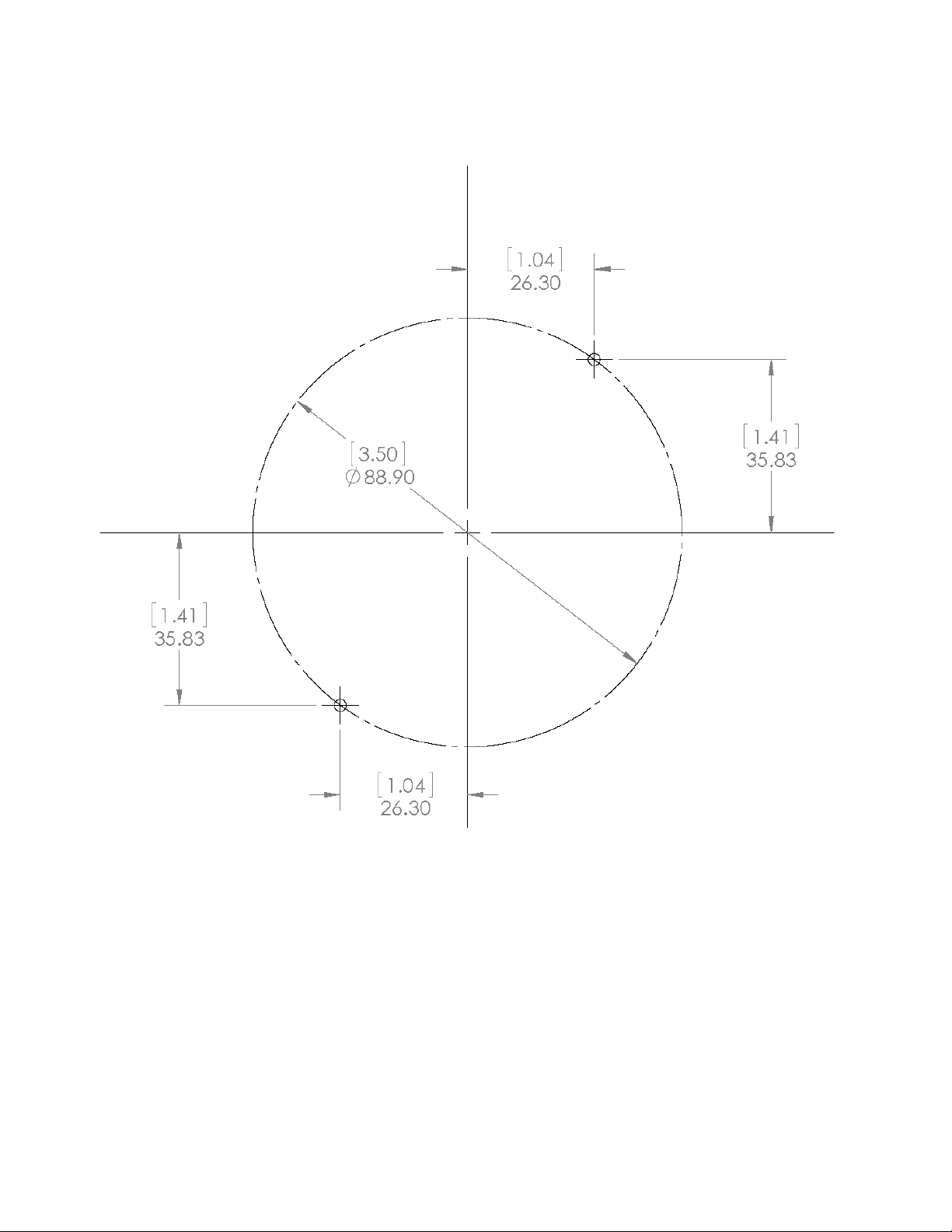
Direct Mounting Template
X2 and XD2 Two-Radio Access Points
7

1.800.947.7871 Toll Free in the US
+1.805.262.1600 Sales
+1.805.262.1601 Fax
2101 Corporate Center Drive
Thousand Oaks, CA 91320, USA
To learn more visit:
xirrus.com or
email info@xirrus.com
© 201 Xirrus, Inc. All Rights Reserved. The Xirrus logo is a registered trademark of Xirrus, Inc.
All other trademarks are the property of their respective owners. Content subject to change without notice.
812-0085-012 Rev A

Wireless Access Point
Appendix C: Notices (XD and XR500/600 Series Only)
This appendix contains the following information:
“Notices” on page 539
“EU Directive 1999/5/EC Compliance Information” on page 546
“Compliance Information (Non-EU)” on page 553
“Safety Warnings” on page 555
“Translated Safety Warnings” on page 556
“Software License and Product Warranty Agreement” on page 557
“Hardware Warranty Agreement” on page 563
This Appendix contains Notices, Warnings, and Compliance information for
the XD and XR500/600 Series only.
For Notices, Warnings, and Compliance information for outdoor products,
please see the Quick Installation Guide for that product.
For Notices, Warnings, and Compliance information for all other APs,
please see “Notices (XR-1000 to XR-6000 Indoor Models)” on page 563.
Notices
Wi-Fi Alliance Certification
www.wi-fi.org
FCC Notice
This equipment has been tested and found to comply with the limits for a Class B
digital device, pursuant to Part 15 of the FCC rules. These limits are designed to
provide reasonable protection against harmful interference in a residential
installation. This equipment generates, uses and can radiate RF energy and, if not
539
 Loading...