

Cambium Networks XD2230 Users Manual
XD2-230 Two-Radio Access Points
1
Quick Installation Guide
For the XD2-230 AP
The XD2-230 Access Point (AP) is part of the Xirrus wireless portfolio. With two
omnidirectional 802.11ac radios, an integrated controller, and cloud management,
this AP delivers robust wireless connectivity.
The XD2-230 (Model XD2230) AP’s radio1 is a dual-band (2.4GHz/5GHz) 3x3
802.11ac Wave 1 radio, set to 2.4GHz by default. Radio2 is a 5GHz-only Wave 2
radio.
This Guide covers the steps required to install and start these APs.
You Need the Following Items
Power and Ethernet connection(s) to your wired network using Cat 5e or Cat 6 cables:
GIG1/POE—This Gigabit port powers the AP via Power over Ethernet (PoE) using a Cat 5e or Cat 6 cable
that also carries data traffic. See below for Power details.
GIG2—This second, data-only Gigabit port is only available on the XD2-240, and provides additional
bandwidth. Its use is optional. Connect with Cat 5E or Cat 6 cable.
AP must be connected to PoE networks without routing cabling to the outside plant. This ensures that cabling is
not exposed to lightning strikes or possible crossover from high voltage lines. AP, PoE injectors, and switches
must be installed and used indoors. The total Cat 5e or Cat 6 cable length from the switch to the AP must be no
more than 100 m, including all cable segments.
Power—See the matrix below to select a compatible PoE switch or Xirrus-supplied injector for your AP. XD2
models require 802.3at. If using an injector, you must provide a data connection from the switch to the injector
as well as another cable from the injector's OUT port to the AP’s GIG1/POE port.
AP Type
XD2-230
Injector or Switch
Generic PoE+
(802.3
PoE+ Switch
(802.3at)
Xirrus
at)
XP1-MSI-30
XP1-MSI-75M
(POE-75U-1UP-X)
XP1-MSI-75
XP8-MSI-70M
XP2-MSI-95M
Apply power to GIG1/POE port only—other AP Gigabit ports will not draw power if connected to a
powered switch port, and AP LEDs will not light.
If you are using a POE switch, it is imperative that you know that the switch has sufficient power budget
to power all connected devices.
Xirrus XD2 APs are Type 2, Class 4 POE-802.3at devices. If your switch vendor provides a setting for the
type of powered-device detection with options such as Legacy, 4-Point, or BOTH, set the port to BOTH or
4-Point. Do not use settings intended for legacy devices.
1
XD2-230 Two-Radio Access Points
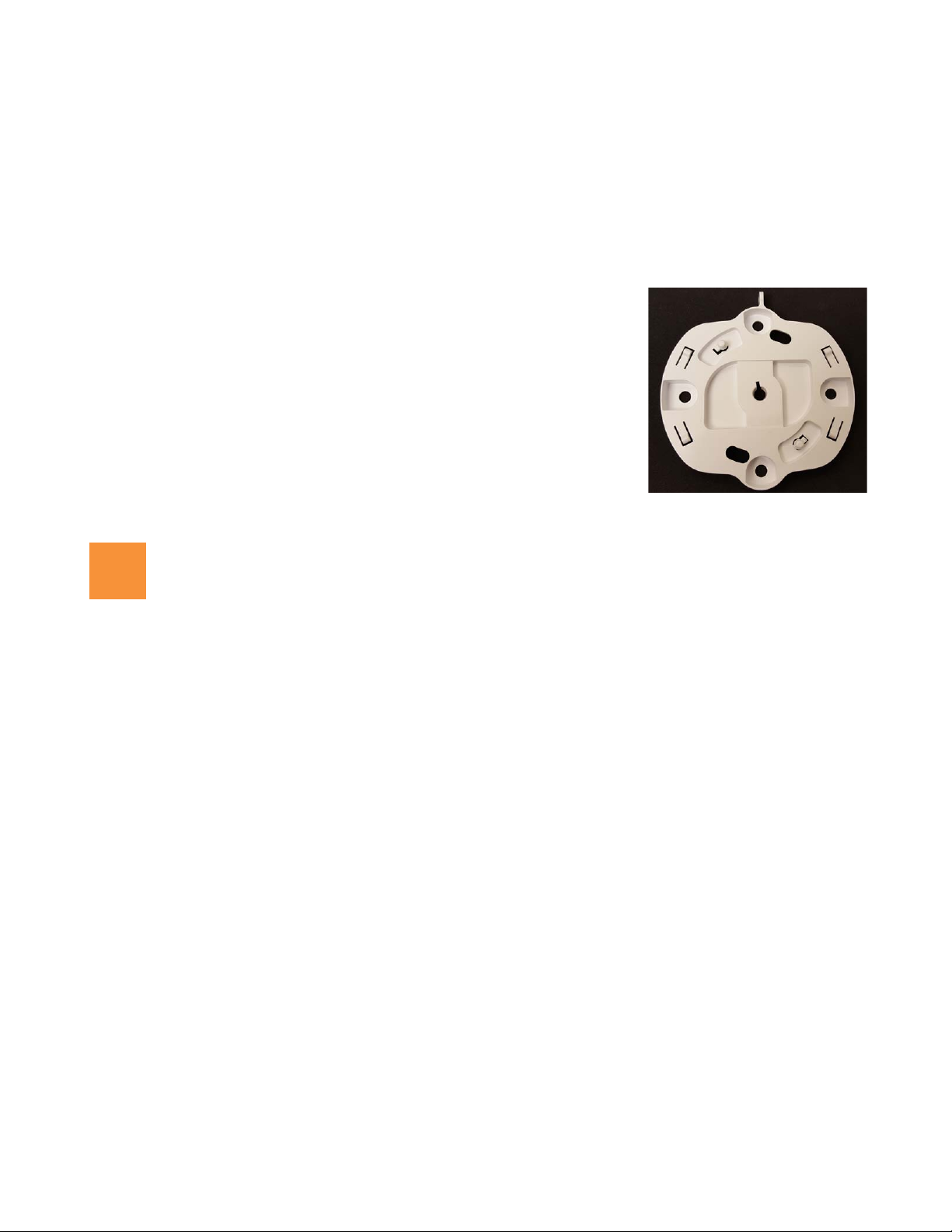
AP Mounting Plate (front)
This side faces the AP
2
Access to a Web browser to configure the AP via the Xirrus Management System or directly via the AP’s
Windows Management Interface (WMI).
For a suspended ceiling mount, you need a 7/16” nut driver to attach the mounting plate to the T-Bar clips.
(See “Install Mounting Hardware” on page 3.) Do not use old T-Bar clips or studs from XN or XS APs with the
X2 and XD2 Series—they will damage the AP case.
NOTE: Leave protective plastic film on the AP until installation is complete to avoid leaving marks on the AP.
Mounting Options
Direct Ceiling Mount—for a more secure mount, use the furnished
mounting plate with at least two user-supplied screws. Or you may mount
directly to the ceiling with two user-supplied screws (we recommend max
screw size #8, Pan Head type). In either case, you must use screws that are
appropriate for the ceiling construction material.
Suspended Ceiling Grid Mount—See photos at right and on Page 3. Use the
mounting plate with the two supplied T-Bar clips (for 15/16” ceiling grid).
For a slotted ceiling grid, T-slot bolts are available for attaching the
mounting plate to slots in the grid.
Wall Mount—use a Wall Mount Accessory Kit (XE-500-WALL), which
contains a mounting plate, wall mount bracket, and three screws (1/4”
Plastite).
Choose a Suitable Location
Choose an indoor location that is central to your users, that is away from heat sources. To ensure good air flow,
it is essential that the AP’s vents are not blocked.
The AP should be installed parallel to the ground (i.e., in a horizontal position, not tilted on its side). The AP
should not be more than 30 feet (9m) above the ground (or the level at which receiving devices will be used).
For atypical installations, please verify the resulting signal coverage.
The location must be capable of supporting the weight of the AP and the mounting bracket (about 2 lb total).
For optimal placement, we recommend that a predictive survey be performed by a qualified Xirrus partner.
Maintain a distance of at least 50 feet (15m) between additional APs.
Keep the unit away from electrical devices or appliances that generate RF noise—at least 3 to 6 ft (1m - 2m).
2

Install Mounting Hardware
3
XD2-230 Two-Radio Access Points
3A—Ceiling Mount
3C—Wall Mount with Bracket
3B—Ceiling Grid Mount with Mounting Plate
3A—Ceiling Mount
We recommend use of the supplied AP mounting plate, which offers a more secure mount and ease of dismount.
1. Remove the mounting plate from the back of the AP (push it against the AP and twist it to the left). Use the
holes on the mounting plate to mark the placement of at least two user-supplied screws to install in the ceiling.
If not using the mounting plate, mark the locations for the two mounting screws on the ceiling—the centers are
3.5” (8.9 cm) apart.
2. Drill and prepare holes for the screws as appropriate.
3. Cut an access hole for the cable(s) in the ceiling and draw enough cable through to attach to the AP after it is
installed.
4. If using the mounting plate, align it over the prepared holes. Secure the plate with the screws. Do not over-
tighten.
If not using the mounting plate, install two screws at the marked locations so that they protrude 1/8” (.3 cm)
between the mounting surface and the head of the screw.
5. Proceed to “Connect Cables and Install AP” on page 4.
NOTE: The AP must not be disassembled! If not using the mounting plate, do not remove the back of the AP to tighten the
screws after mounting to ceiling.
3B—Ceiling Grid Mount with Mounting Plate
1. Remove the mounting plate from the back of the AP (push it against the
AP and twist it to the left). For T-Bar clips, use two of the four holes on
the AP mounting plate to mark the placement of two T-Bar clips on the
metal ceiling support grid.
Twist the two supplied T-Bar clips onto the metal ceiling grid at the
marked locations and tighten the screw posts to 10-12 lbf.ft (1.38-1.66 kgf.m). Do not over- tighten the screw
posts.
2. Cut an access hole in the ceiling tile and draw the cable(s) through.
3. Align the AP mounting plate over the screw posts of the T-Bar clips and secure it to the two posts using the
nuts provided. Tighten the nuts to 10-12 lbf.ft (1.38-1.66 kgf.m), but do not over tighten.
4. Proceed to “Connect Cables and Install AP” on page 4.
3
 Loading...