

Cambium Networks 450 Series, PTP 450, PMP 450b, PTP 450b, PMP 450 AP Quick Start Manual
...
1
QUICK START GUIDE
450 SERIES RADIOS
pmp-2386

2
Accuracy
While reasonable efforts have been made to assure the accuracy of this document, Cambium Networks
assumes no liability resulting from any inaccuracies or omissions in this document, or from use of the
information obtained herein. Cambium Networks reserves the right to make changes to any products
described herein to improve reliability, function, or design, and reserves the right to revise this document and
to make changes from time to time in content hereof with no obligation to notify any person of revisions or
changes. Cambium Networks does not assume any liability arising out of the application or use of any
product, software, or circuit described herein; neither does it convey license under its patent rights or the
rights of others. It is possible that this publication may contain references to, or information about Cambium
Networks products (machines and programs), programming, or services that are not announced in your
country. Such references or information must not be construed to mean that Cambium Networks intends to
announce such Cambium Networks products, programming, or services in your country.
Copyrights
This document, Cambium Networks products, and 3rd Party software products described in this document
may include or describe copyrighted Cambium Networks and other 3rd Party supplied computer programs
stored in semiconductor memories or other media. Laws in the United States and other countries preserve for
Cambium Networks, its licensors, and other 3rd Party supplied software certain exclusive rights for
copyrighted material, including the exclusive right to copy, reproduce in any form, distribute and make
derivative works of the copyrighted material. Accordingly, any copyrighted material of Cambium Networks, its
licensors, or the 3rd Party software supplied material contained in the Cambium Networks products described
in this document may not be copied, reproduced, reverse engineered, distributed, merged or modified in any
manner without the express written permission of Cambium Networks. Furthermore, the purchase of
Cambium Networks products shall not be deemed to grant either directly or by implication, estoppel, or
otherwise, any license under the copyrights, patents or patent applications of Cambium Networks or other 3rd
Party supplied software, except for the normal non-exclusive, royalty free license to use that arises by
operation of law in the sale of a product.
Restrictions
Software and documentation are copyrighted materials. Making unauthorized copies is prohibited by law. No
part of the software or documentation may be reproduced, transmitted, transcribed, stored in a retrieval
system, or translated into any language or computer language, in any form or by any means, without prior
written permission of Cambium Networks.
License Agreements
The software described in this document is the property of Cambium Networks and its licensors. It is furnished
by express license agreement only and may be used only in accordance with the terms of such an agreement.
High Risk Materials
Cambium and its supplier(s) specifically disclaim any express or implied warranty of fitness for any high risk
activities or uses of its products including, but not limited to, the operation of nuclear facilities, aircraft
navigation or aircraft communication systems, air traffic control, life support, or weapons systems (“High Risk
Use”). Any High Risk is unauthorized, is made at your own risk and you shall be responsible for any and all
losses, damage or claims arising out of any High Risk Use.
www.cambiumnetworks.com
Cambium Networks and the stylized circular logo are trademarks of Cambium Networks, Ltd. All other
trademarks are the property of their respective owners.
© Copyright 2019 Cambium Networks, Ltd. All rights reserved.

3
Contents
English (UK | IE | NO)......................................................................................................................... 7
1. Introduction ........................................................................................................................................................................................ 7
2. Product Description ........................................................................................................................................................................ 7
3. Installation & Operation ................................................................................................................................................................. 7
4. Product Safety information .......................................................................................................................................................... 8
5. Typical Installation ........................................................................................................................................................................... 9
6. Hardware overview ........................................................................................................................................................................ 10
7. Installing and Connecting the Equipment ........................................................................................................................... 14
8. Configuring a 450 series radio to meet national regulations ...................................................................................... 16
9. External Antennas ........................................................................................................................................................................... 17
10. Other Accessories available from Cambium Networks ................................................................................................. 19
11. Operating in the EU ...................................................................................................................................................................... 20
12. Cambium Networks ....................................................................................................................................................................... 22
Czech (CZ) ......................................................................................................................................... 23
1. Úvod .....................................................................................................................................................................................................23
2. Popis produktu ................................................................................................................................................................................23
3. Instalace a provoz ..........................................................................................................................................................................23
4. Bezpečnostní informace k produktu ..................................................................................................................................... 24
5. Typické způsoby instalace ..........................................................................................................................................................25
6. Přehled hardwaru .......................................................................................................................................................................... 26
7. Montáž a připojení zařízení ....................................................................................................................................................... 30
8. Nastavení rádiových zařízení 450 podle národních předpisů .....................................................................................32
9. Externí antény ................................................................................................................................................................................. 34
10. Další příslušenství dodávané společností Cambium Networks .................................................................................. 35
11. Provoz v Evropské unii ............................................................................................................................................................... 36
12. Cambium Networks ...................................................................................................................................................................... 38
French (FR) ........................................................................................................................................ 39
1. Introduction ..................................................................................................................................................................................... 39
2. Description du produit ................................................................................................................................................................ 39
3. Installation et fonctionnement: ................................................................................................................................................ 39
4. Informations de sécurité du produit...................................................................................................................................... 40
5. Installation typique ........................................................................................................................................................................ 41
6. Aperçu des caractéristiques ..................................................................................................................................................... 42
7. Installation et connexion de l'équipement .......................................................................................................................... 46
8. Configuration d'une radio série 450 conformément aux règlementations nationales.................................... 48
9. Antennes externes ........................................................................................................................................................................ 50

4
10.
Autres Accessoires disponible auprès de Cambium Networks ...................................................................................51
11. Exploitation dans l'UE ...................................................................................................................................................................52
12. Cambium Networks ...................................................................................................................................................................... 54
German (DE) ...................................................................................................................................... 55
1. Einleitung .......................................................................................................................................................................................... 55
2. Produktbeschreibung .................................................................................................................................................................. 55
3. Installation & Betrieb .................................................................................................................................................................... 56
4. Informationen zur Produktsicherheit .................................................................................................................................... 56
5. Standardinstallation ......................................................................................................................................................................57
6. Hardware-Übersicht ..................................................................................................................................................................... 59
7. Installation und Verbindung der Geräte .............................................................................................................................. 63
8. Konfiguration eines Funkmoduls der Serie 450 unter Berücksichtigung nationaler Vorschriften ............ 65
9. Externe Antennen ......................................................................................................................................................................... 67
10. Von Cambium Networks erhältliches Zubehör ................................................................................................................. 69
11. Betrieb in der EU ........................................................................................................................................................................... 70
12. Cambium Networks ........................................................................................................................................................................ 71
Spanish (ES) ...................................................................................................................................... 73
1. Introducción ......................................................................................................................................................................................73
2. Descripción del producto ...........................................................................................................................................................73
3. Instalación y operación ................................................................................................................................................................73
4. Información de seguridad del producto .............................................................................................................................. 74
5. Instalación típica .............................................................................................................................................................................75
6. Vista de conjunto del hardware .............................................................................................................................................. 76
7. Instalación y conexión del equipo .......................................................................................................................................... 80
8. Configuración de una radio de la serie 450 conforme a la normativa nacional correspondiente ............. 82
9. Antenas externas ........................................................................................................................................................................... 84
10. Otros accesorios disponibles de Cambium Networks ................................................................................................... 85
11. Operación en la UE ....................................................................................................................................................................... 86
12. Cambium Networks ...................................................................................................................................................................... 89
Hungarian (HU) ................................................................................................................................. 90
1. Az útmutató bemutatása ........................................................................................................................................................... 90
2. A termékek ismertetése.............................................................................................................................................................. 90
3. Telepítés és üzemeltetés ............................................................................................................................................................ 90
4. Termékbiztonsági információk ................................................................................................................................................. 91
5. Jellemző telepítési módok ......................................................................................................................................................... 92
6. Hardver – áttekintés ..................................................................................................................................................................... 93
7. A berendezés felszerelése és csatlakoztatása .................................................................................................................. 97
8. 450-es szériájú rádió konfigurálása az országos szabályokhoz ............................................................................... 99
9. Külső antennák ................................................................................................................................................................................ 101

5
10.
A Cambium Networkstől beszerezhető egyéb tartozékok, kiegészítők ................................................................ 102
11. EU-beli használhatóság.............................................................................................................................................................. 103
12. Cambium Networks ..................................................................................................................................................................... 105
Italian (IT) ......................................................................................................................................... 106
1. Introduzione ................................................................................................................................................................................... 106
2. Descrizione del prodotto ......................................................................................................................................................... 106
3. Installazione e funzionamento ............................................................................................................................................... 106
4. Informazioni sulla sicurezza del prodotto.......................................................................................................................... 107
5. Installazione tipica....................................................................................................................................................................... 108
6. Panoramica dell’hardware ....................................................................................................................................................... 109
7. Installazione e collegamento dell’apparecchiatura ......................................................................................................... 113
8. Configurazione di un’apparecchiatura radio della serie 450 in modo che sia conforme alle normative
nazionali ........................................................................................................................................................................................................ 115
9. Antenne esterne ............................................................................................................................................................................. 117
10. Altri accessori disponibili presso Cambium Networks .................................................................................................. 118
11. Funzionamento nell’UE ............................................................................................................................................................... 119
12. Cambium Networks ..................................................................................................................................................................... 120
Polish (PL) ......................................................................................................................................... 122
1. Wprowadzenie .............................................................................................................................................................................. 122
2. Opis produktu ................................................................................................................................................................................ 122
3. Instalacja i obsługa ...................................................................................................................................................................... 123
4. Bezpieczeństwo użytkowania ................................................................................................................................................. 123
5. Typowa instalacja ......................................................................................................................................................................... 124
6. Omówienie sprzętu ...................................................................................................................................................................... 125
7. Instalacja i podłączanie sprzętu .............................................................................................................................................. 130
8. Konfiguracja modułu radiowego serii 450 w celu spełnienia krajowych przepisów ...................................... 132
9. Zewnętrzne anteny ...................................................................................................................................................................... 134
10. Inne akcesoria oferowane przez Cambium Networks .................................................................................................. 135
11. Możliwość funkcjonowania na obszarze UE ...................................................................................................................... 136
12. Cambium Networks ..................................................................................................................................................................... 138
Turkish (TR) ..................................................................................................................................... 140
1. Giriş .................................................................................................................................................................................................... 140
2. Ürün Açıklaması ........................................................................................................................................................................... 140
3. Kurulum ve Çalıştırma ................................................................................................................................................................ 140
4. Ürün Güvenlik bilgileri ................................................................................................................................................................. 141
5. Tipik Kurulum ................................................................................................................................................................................. 142
6. Donanıma genel bakış ................................................................................................................................................................. 143
7. Ekipmanı Kurma ve Bağlama ................................................................................................................................................... 147
8. 450 serisi cihazı ulusal düzenleme şartlarını yerine getirecek şekilde yapılandırma ....................................... 149

6
9.
Harici Antenler ................................................................................................................................................................................ 151
10. Cambium Networks tarafından sağlanabilen Diğer Aksesuarlar ............................................................................... 152
11. AB'de Çalıştırma ............................................................................................................................................................................ 153
12. Cambium Networks ..................................................................................................................................................................... 155

7
English (UK | IE | NO)
1. Introduction
Thank you for purchasing Cambium Networks 450 series platform equipment. This Quick Start Guide is
provided to assist operators in acquiring a high-level understanding of the 450 series platform hardware,
installation methods, initial login procedures, and safety/warranty information.
This Quick Start Guide applies to all 450 series platform products.
2. Product Description
The Cambium Networks 450 series of radio products supports data transmission over Point to MultiPoint
(PMP) and Point to Point (PTP) microwave links. This radio equipment (referred to as ‘outdoor units’ or ODUs)
is intended for professional applications for fixed outdoor installations only.
PMP (Point-to-Multipoint)
PTP (Point-to-Point)
The PMP 450 series platform consists of an
Access Point (AP) and multiple Subscriber
Module (SM) Outdoor Units (ODUs). The radio
link operates on a single frequency channel in
each direction using Time Division Duplex (TDD).
The AP is available as a connectorized unit to be
connected to an external antenna or as an
integrated unit with a sector antenna.
The SM is available as a connectorized unit to be
connected to an external antenna or as an
integrated unit with a directional antenna.
The PTP 450 series platform consists of two BH
(Backhaul) ODUs. In order to establish a radio
link between two BH radios, the end user must
configure one as a BHM (Backhaul Master) and
the other as a BHS (Backhaul Slave).
The radio link operates on a single frequency
channel using Time Division Duplex (TDD).
The PTP series platform is available as a
connectorized unit to be connected to an
external antenna or as an integrated unit with a
directional antenna.
3. Installation & Operation
Installation and operation of this product is complex, and Cambium therefore recommends professional
installation and management of the system to ensure that operation complies with the regulations of the
region where the product is installed. Please follow the instructions in this Quick Start Guide. Further guidance
on PMP and PTP installation and operation is available in the product user guide, see links at the end of this
Quick Start Guide.

8
The installer must have sufficient skills, knowledge and experience to perform the installation task and is
responsible for:
• Familiarity with current applicable national regulations including radio regulations, electrical
installation regulations, surge protection regulations and ‘working at heights’ regulations
• Installation in accordance with Cambium Networks instructions
• Confirming that the equipment settings are compliant with national or regional regulations
• Familiarity with training material available on the Cambium Networks website (see link below)
Please observe the important instructions below during installation. This will set the equipment in compliance
with national regulatory regulations and ensure legal operation.
• Ensure that the 450 series equipment is fitted with the latest application code. The software version
must be Canopy 16.x.x or later in order to comply with national regulations. Software is available from
the Cambium Support Centre web site, see link below.
4. Product Safety information
Observe the following safety rules:
• Ensure that the Outdoor Unit (ODU) and the structure on which it is mounted is capable of
withstanding the maximum wind speeds at a proposed site.
• Ensure the equipment is not powered during installation. Always disconnect equipment from its
power source before servicing.
• Harmful levels of RF radiation are present close to the antenna when the transmitter is on.
Observe the minimum safe distance limit for 450 products provided below.
Ensure that equipment is installed in a position avoiding any radiation hazard to humans.
Exercise extreme care when working at heights. Observe national ‘working at heights’ regulations. Use trained
‘competent’ staff.
Exercise extreme care when working near power lines.
Always use a qualified electrician to install cabling.
The Outdoor Unit (ODU) must be properly grounded.
Always use the specified Cambium 450 platform power supply units (PSU) to power the equipment. Failure to
use the specified Cambium supplied PoE could result in equipment damage and may cause a safety hazard.
Do not deploy Cambium Networks power injectors in an outdoor environment
Structures, equipment and people must be protected against electrostatic discharge: -
by siting equipment in a lightning protection zone
by installation of appropriate lightning conductors to conduct the surge current to ground via a separate
preferential solid path.
ground bonding and transient voltage surge suppression is recommended. Use Cambium specified surge
suppressors.
The ODU enclosure may be hot to the touch when in operation.
Use outdoor rated cables for connections that will be exposed to the outdoor environment. Install Cambium
recommended cables.
9
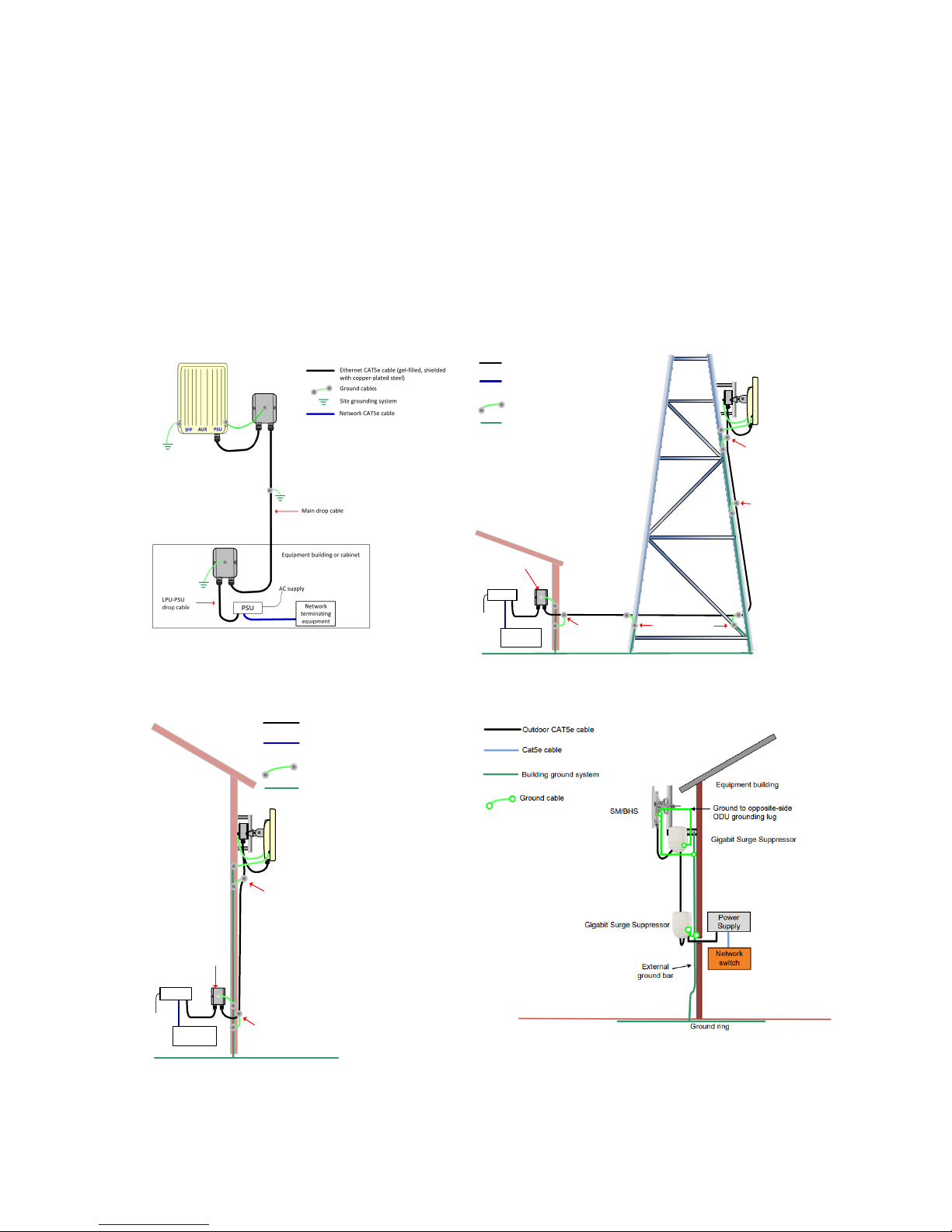
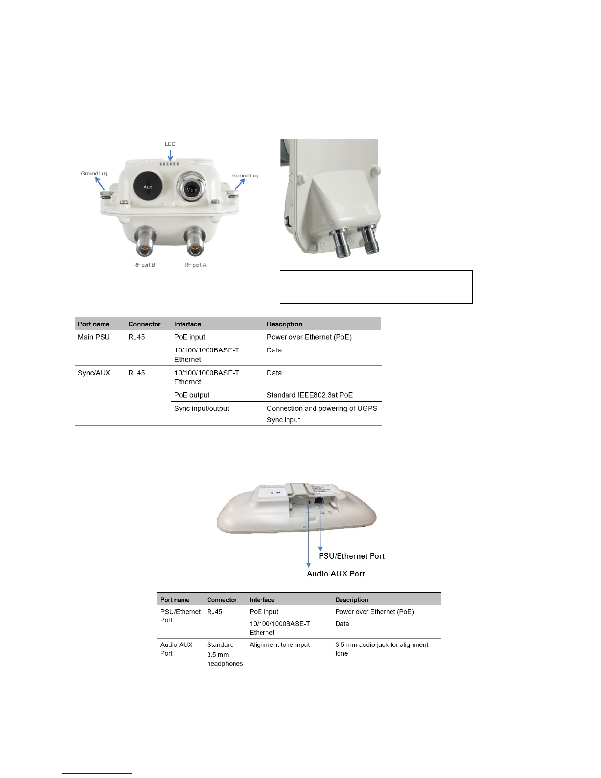
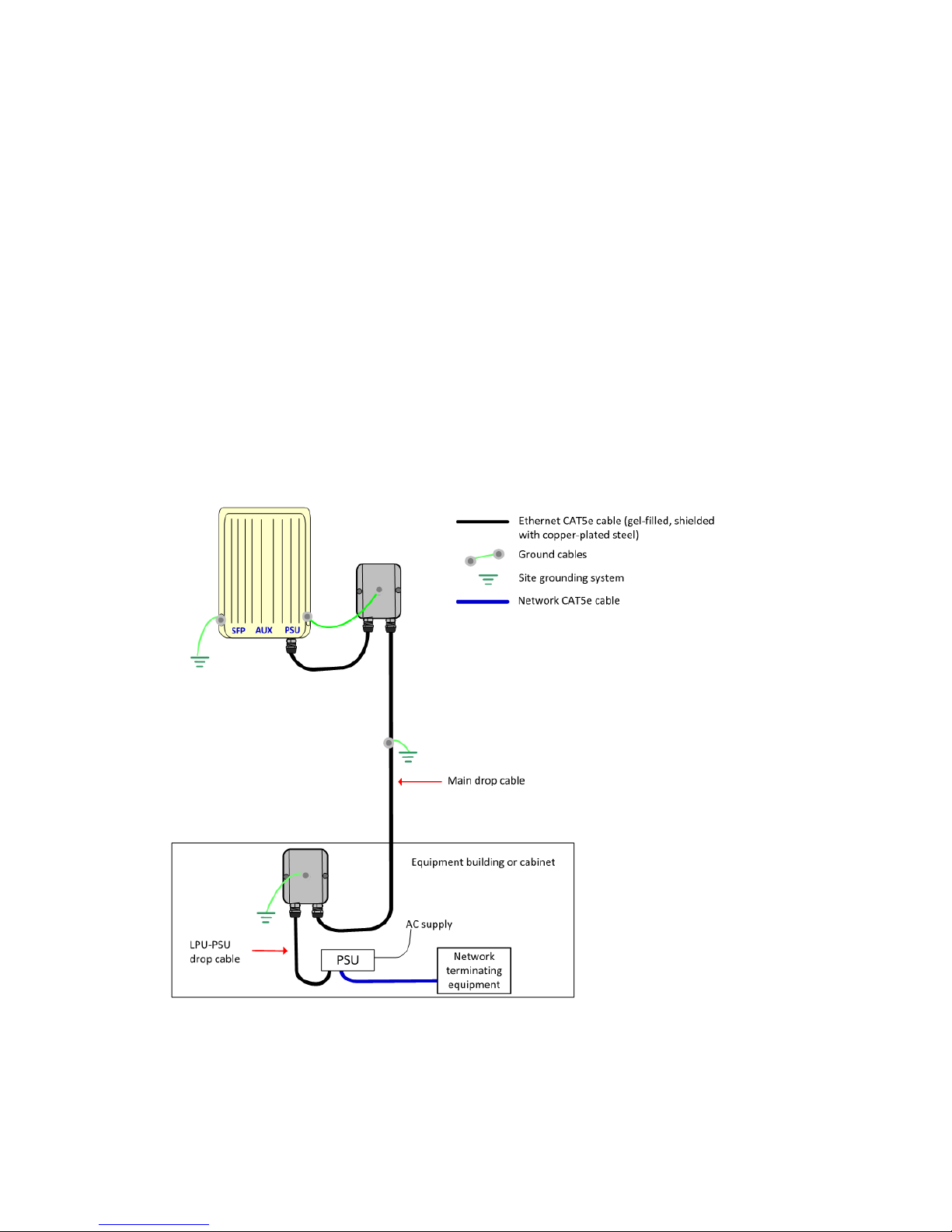
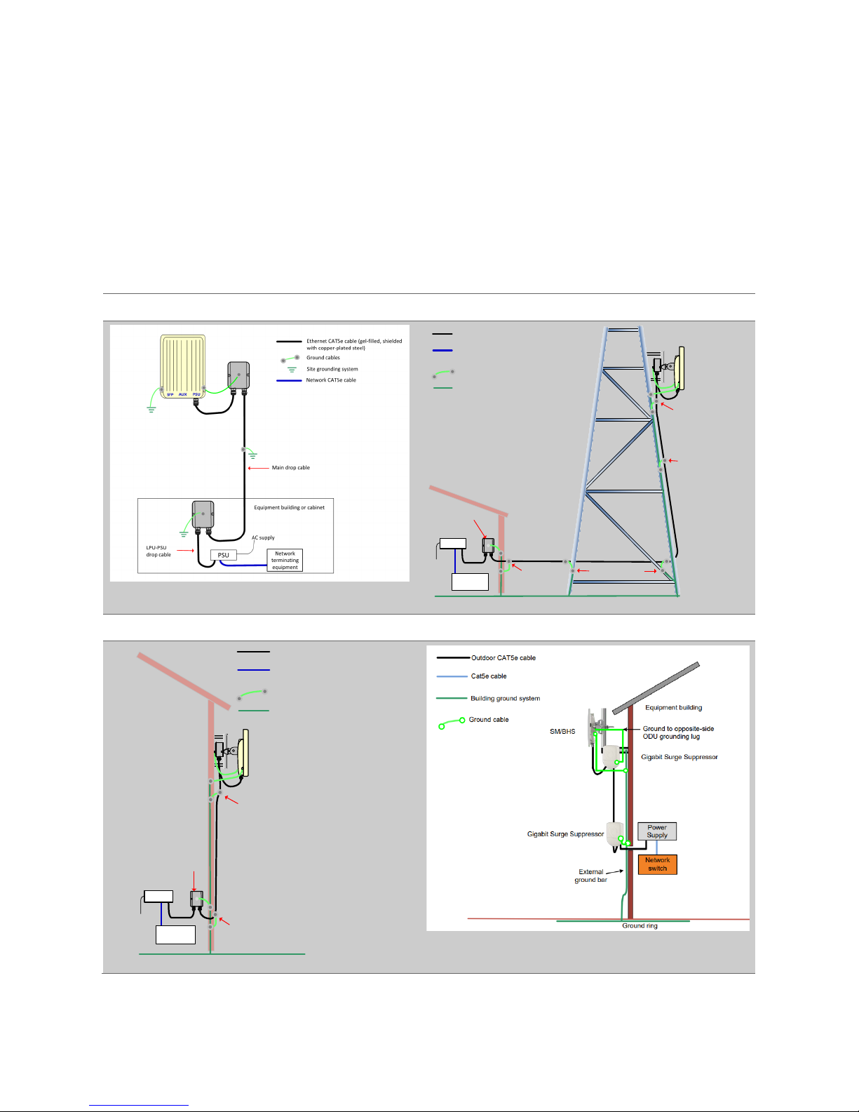
5. Typical Installation
In the simplest configuration (Figure 1), the data path from the network equipment (Ethernet interface), is
routed via a Power over Ethernet (PoE) injector (labelled ‘PSU’ in the figure) then via a copper cable to the
ODU (PSU port). Surge protection units should also be deployed as shown. A typical mast or tower
installation and wall installations is shown below (Figure 2, 3 & 4). Consult the user guide for detail of more
configurations.
Always site the radio equipment in a lightning protection zone:-
The equipment must be lower than the top of the tower or building or its lightning air terminal
The tower or building must be correctly grounded
Figure 1 Basic configuration Figure 2 Mast or tower installation
ODU
AC
supply
PSU
Network
equipment
ODU grou nd cables
Power over Ethernet CAT5e cable (gel-filled,
shielded with copper-plat ed stee l)
Network CAT5e cable
Site grounding system
Bottom LPU
First point of contact
between drop cable
and tower
Tower ground bar
Ground ring
Intermediate
ground cable(s)
as req uir ed
Build ing
en try
Equipment building
or cabinet
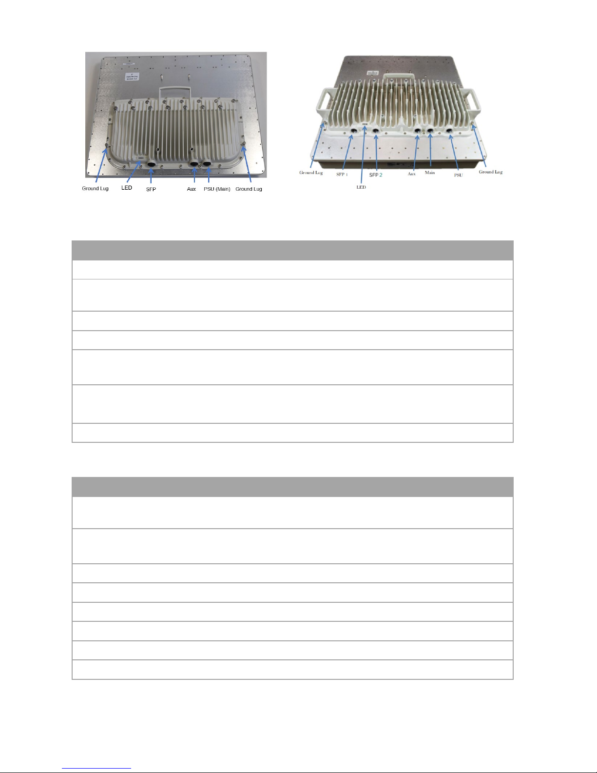
Figure 3 Wall installation (450i) Figure 4 Wall installation (450 SM)
ODU
PSU
Network
equipment
ODU ground cables
Site grounding system
Bottom LPU
Ground ring
First point of contact
between drop cable
an d w all
Building entry
Power over Ethernet CAT5e cabl e (gelfilled, shielded with copper-pl ated st eel)
Network Cat5e cab le
AC supply
10
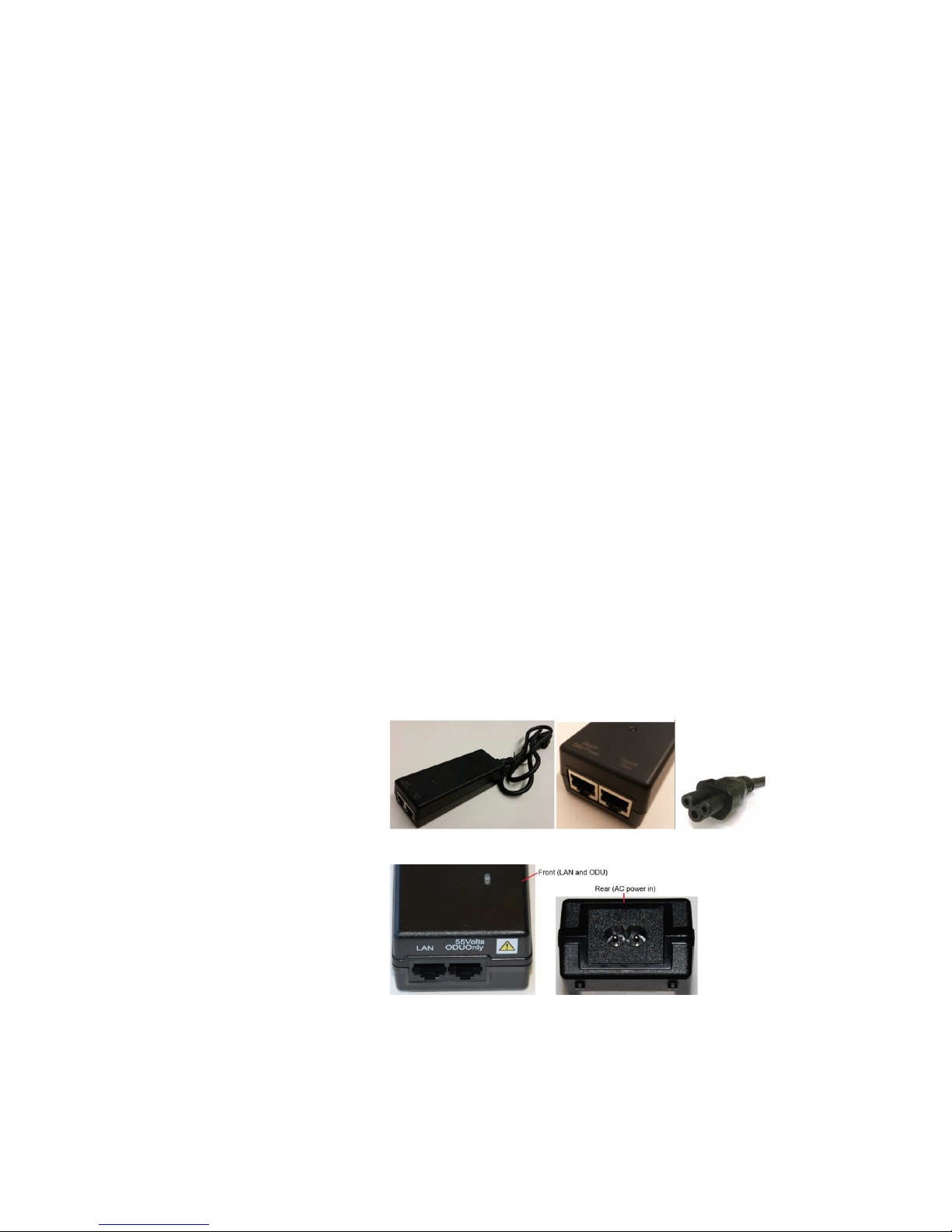
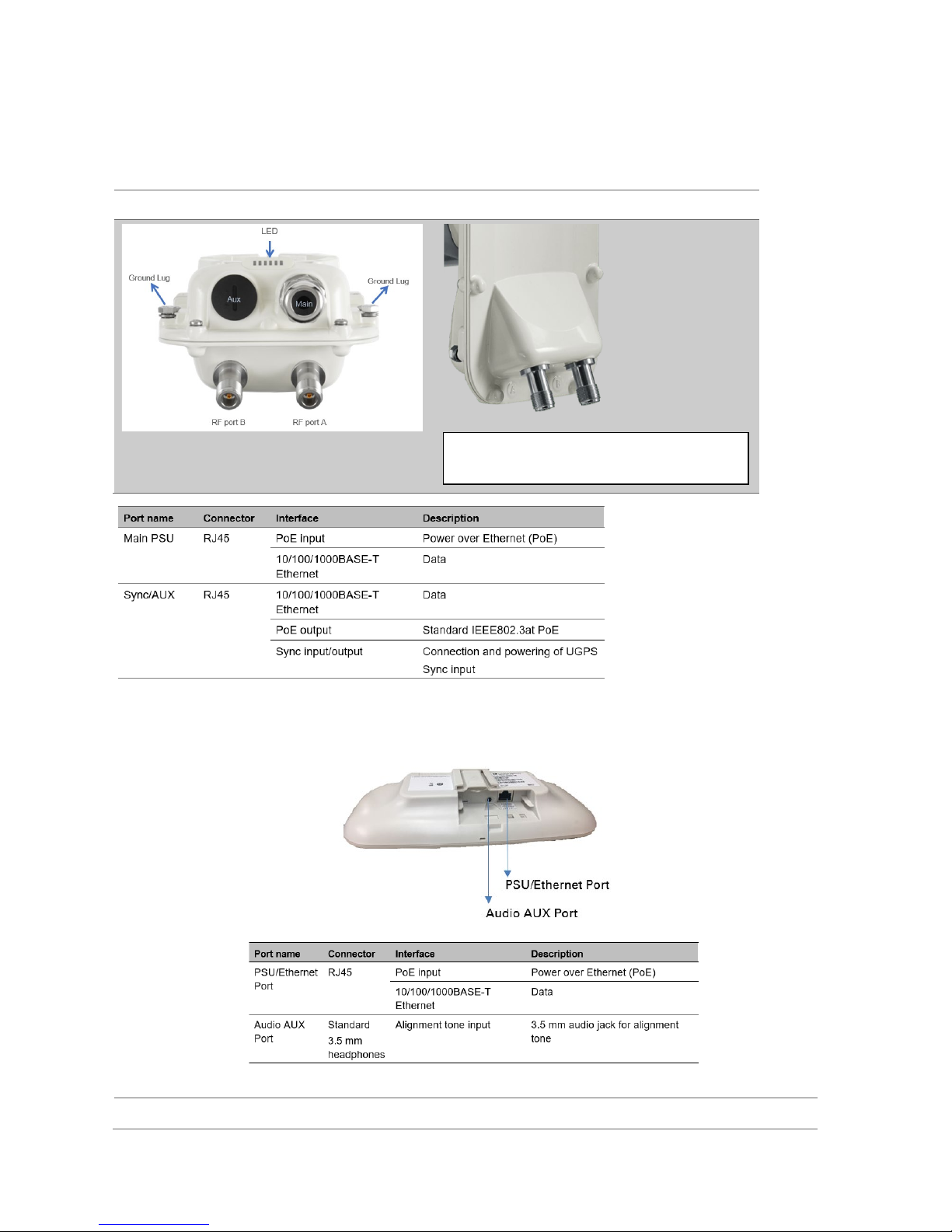
6. Hardware overview
PMP/PTP 450i interfaces
The Ethernet and Sync/AUX ports are located on the rear of the integrated and connectorized ODUs.
The connectorized ODU is shown here.
View of interface connections
The front of the connectorized ODU
PMP/PTP 450b interfaces
The Mid-Gain is unit shown here. The interfaces are the same for the high-gain
unit.
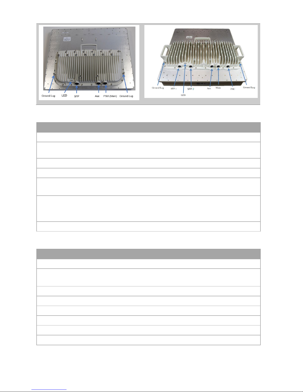
PMP 450m AP interfaces
5 GHz PMP 450m
3 GHz PMP 450m
(N type female connectors for RF cable
11
5 GHz PMP 450m AP interface definition
Port name
Connector
Interface function
Description
PSU (Main)
RJ45 PoE input Power over Ethernet (PoE)
10/100/1000 BaseT
Ethernet
Data
Aux
RJ45 10/100 BaseT Ethernet Data
PoE output Standard IEEE802.3at PoE
Sync input/output
Connection and powering of UGPS Sync
input
SFP
SFP
2.5 Gbps Copper Ethernet
and 1 Gbps Copper
Data and Management Services.
Plug-in SFP module is purchased separately
Ground Lugs
10 AWG copper wire For grounding the unit
3 GHz PMP 450m AP interface definition
Port name
Connector
Interface function
Description
PSU
4-pin DC power input
40 V – 60 V plus Cambium Sync-overpower
Main
RJ45 Ethernet
10/100/1000Base-T Ethernet, plus
Cambium Sync-over-data
Aux
RJ45 Ethernet 10/100Base-T Ethernet with PoE out
Synchronization UGPS synchronization port
Alignment Audio tones
SFP 1
SFP Ethernet SFP module
SFP 2
SFP Ethernet SFP module (single or dual)
Ground Lugs
10 AWG copper wire For grounding the unit
12
Power supplies
Power is supplied to the ODU by a PoE injector, except for 3 GHz PMP 450m where power and data are
supplied separately. All power injectors / power supplies in the Cambium Networks range are designed for an
indoor environment. The following table summarizes the Cambium Networks power supply variants available
for each 450 radio model.
Model
30 VDC
56 VDC
802.3af
802.3at
N000900L001B
/C
Gigabit (15W)
N000900L002A 100 Base T (15W) - obsolete
N000000L034A (AC) – 30W, 56VDC
N000065L001C (AC) – 60W
C000065L002C (AC+DC) – 100W
N000000L054B (AC)
54V 240W
PMP 450 AP
X
- - - X X* - - - -
PMP 450 SM
X
- - - X* X* - - - -
PTP 450
X
- - - X* X* - - - -
PMP / PTP 450b
X
- - - X X* - - - -
PMP 450i AP
-
X - X - - X X X -
PMP 450i SM
-
X - X - - X X X -
PTP 450i
-
X - X - - X X X -
5 GHz PMP 450m
-
X - - - - - - X -
3 GHz PMP 450m
-
- - - - - - - - X
*100 Base T-mode only (no Gigabit)
The AC line cord is supplied separately from the power supply. Regional variants are available.
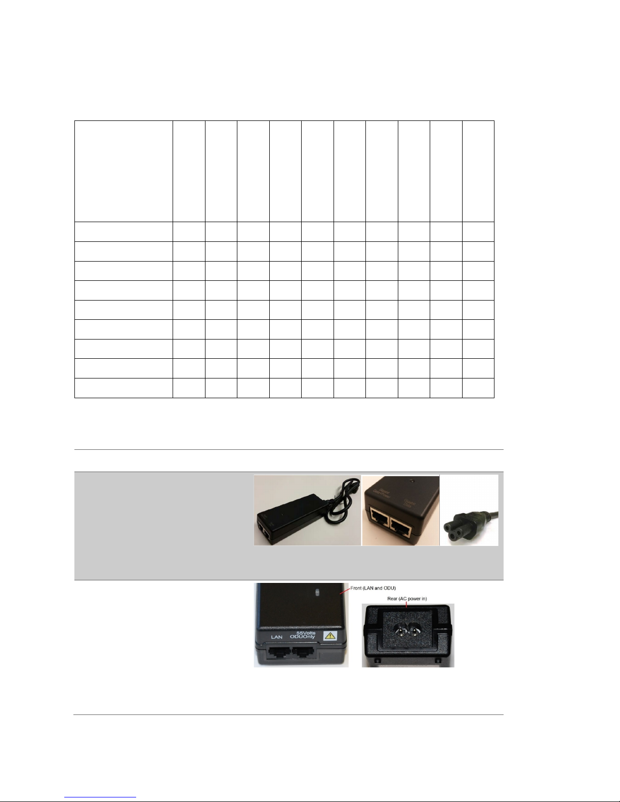
The power supply variants are displayed below:-
Power Injector type
Power Injector views
PMP / PTP 450 / 450b power supply
AC Input: 90-264 VAC, 0.5A rms
DC Output: 30.0 Vdc +/-5%, 15W, 500
mA max
RJ 45 Sockets: Two (Data In and Data
& Power Out)
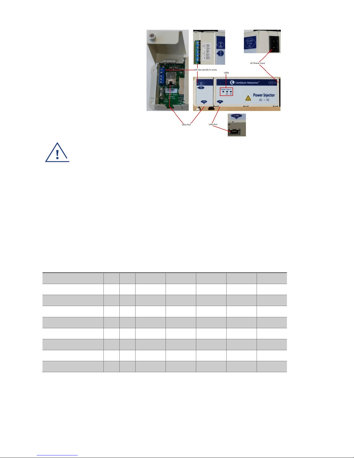
AC power injector (for 450i)
AC power in: AC power input (main
supply)
ODU port: RJ45 socket for connecting
Cat5e cable to ODU
LAN port: RJ45 socket for connecting
Cat5e cable to network equipment
13
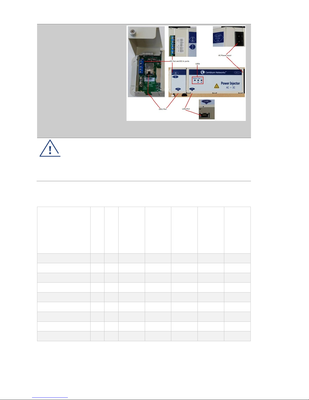
AC+DC Enhanced
Power injector
AC power input: 100-240V 47-63Hz
1.5A
DC In: Alternative DC power supply
input
ODU: RJ45 socket for connecting
Cat5e cable to ODU
LAN: RJ45 socket for connecting
Cat5e cable to network
DC Out: DC power output to a second
PSU (for power supply redundancy)
or to a NIDU
Warning
The PMP 450 Ruggedized High Gain Integrated
Subscriber Module (Cambium part numbers
C035045C014A and C036045C014A), while
encapsulated in a 450i-type enclosure, contains 450
circuitry which must be powered via 30VDC. Powering
these SMs with a 56 VDC will damage the device.
Surge protection units
The following table lists suitable surge suppressors for each 450 series radio model.
Model
30 VDC
56 VDC
C000000L065A
Gigabit Ethernet
Surge Suppressor
600SSH
(100 BASE T)
C000000L033A
Gigabit Ethernet
Surge Suppressor
C000065L007B
Lightning Protection
Unit kit
C000000L114A
DC Lightning
Protection Unit kit
PMP 450 AP
X - X X - - -
PMP 450 SM
X - X X - - -
PTP 450
X - X X - - -
PMP 450b
X - X X - - -
PMP 450i AP
- X - - X X -
PMP 450i SM
- X - - X X -
PTP 450i
- X - - X X -
5 GHz PMP 450m AP
- X - - - X -
3 GHz PMP 450m AP
- - - - - - X
Cambium Networks does NOT recommend deploying Gas Discharge Tube-based surge protection on PMP
450i or PMP 450b platforms.
Other accessories
Cambium Networks offers a wide range of additional accessories such as power cords, drop cables, grounding
cables etc. Please refer to the user guide or ordering guide for further details.
14
7. Installing and Connecting the Equipment
Review national regulations and ensure that all appropriate regulatory licenses are obtained prior to
deployment. Before installation, the location of the ODUs needs to be carefully planned to ensure good radio
coverage and to minimise interference. Use radio planning tools such as LINKPlanner to optimise link
performance. Installation and commissioning of equipment should be carried out by trained personnel.
Basic installation of ODUs
1. Pre-configure the ODU as described in the next section (section 8)
2. Install the ODUs in the powered-down state
3. Locate the ODUs so that the link is unobstructed by the radio horizon and no objects penetrate the
Fresnel zone.
4. For APs, use a local map, compass, and/or GPS device to determine the pointing direction as per the
sector arrangement. Apply the appropriate degree of downward tilt.
5. Attach the cables to the ODU as per the diagram below
a. Connect an Ethernet cable from the ‘Data’ or ‘LAN’ port of the PoE power supply to the
Ethernet port of a suitable laptop
b. Connect the drop cable from ODU to the ‘Data + Power’ or ‘ODU’ port of the power supply
c. Fit the surge suppressors as shown and connect grounding cables as required
d. Connect the power supply to a power source
e. Waterproof the external connections

15
Installing a 450 series Subscriber Module - SM
Additional steps are required to ensure that the SM is aligned correctly.
• A coarse alignment procedure must be executed using the alignment tool or alignment tone.
• Verification of the AP to SM link by reviewing power level, link tests, and reviewing registration and
session counts.
Refer to the user-guide for more detail.
Installing 450 series PTP links
The process for installing a ‘Backhaul Master’ (BHM) is similar to that described for an Access Point. When
installing the ‘Backhaul Slave’ (BHS), a coarse alignment procedure must be executed using the alignment tool
or alignment tone. Refer to the user-guide for more detail.
Consult the 450 series user-guide or training material for further detail of mounting arrangements, cabling
and alignment. The guides are available at the Cambium Networks Web-site, see links at the end of this
document.
16
8. Configuring a 450 series radio to meet national regulations
Cambium recommends that units are pre-configured ‘on the bench’ before being deployed.
Connect the 450 series unit to the PoE power supply and a suitable PC.
• Connect an Ethernet cable from the PC to the ‘data’ port on the PoE supply
• Connect another Ethernet cable from the PoE supply ‘data and power’ port to the 450 radio
• Plug the PoE supply power cord into a power outlet and switch on
• Check that the power LED on the PoE supply illuminates
On the 450 series radio -
• Check that the orange Ethernet LED starts with 10 slow flashes.
• Check that the Ethernet LED then illuminates continuously.
On the PC, configure the Ethernet port for a static IP address using the 169.254.X.X range, avoiding
169.254.0.0 and 169.254.1.1. A good example is 169.254.1.3. Enter a subnet mask of 255.255.0.0. Leave the
default gateway blank.
• Using a web browser, navigate to factory default web address 169.254.1.1 and log-in.
• Enter Username (factory default username is admin) and Password (factory default password is
admin) and click Login.
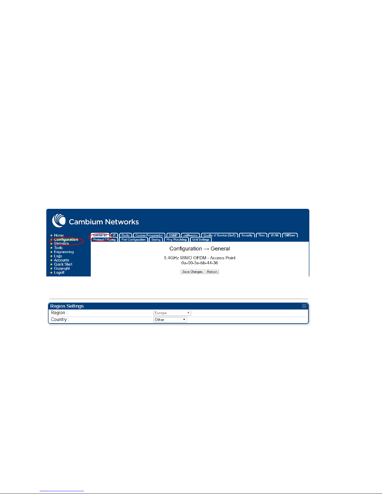
The 450 web interface menu and System Summary page are displayed.
On the menu of left hand side of web page, select ‘Configuration’ as shown:
Click on the ‘General’ tab and scroll down to the ‘Region Settings’ window:
Check that the ’region’ code matches the region where the unit is to be deployed. If it is not, select the correct
region, otherwise do not proceed further.
Click in the ‘Country’ box, and from the drop down list select the country where the unit will be deployed or if
not listed select ‘Other’.
Press the ‘Save Changes’ button and then ‘Reboot’.
When rebooted, log-in again.
Go to the ‘Radio’ tab. From the ‘Radio Configuration’ menu, select the required frequency band and then press
the ‘Save Changes’ button and ‘Reboot’. Once rebooted, log back in and enter the ‘Radio Configuration’ menu
again to select an appropriate carrier and bandwidth. ‘Alternate’ carriers may need to be selected for 5.4GHz
and 5.7Ghz bands for the EU versions of the radio.
17
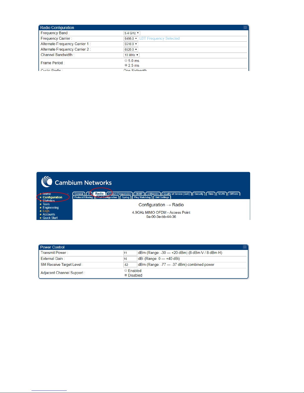
Press the ‘Save Changes’ button and then ‘Reboot’.
After reboot, navigate back to the ‘Power Control’ menu via the ‘Radio tab’. Check that the EIRP is set to the
correct value for the country in which the radio is deployed. Do not proceed further unless the EIRP is set
within the national regulations. If you are configuring a connectorized unit, follow the instructions in the “5
GHz 450i series connectorized units – additional steps” section.
Further set-up steps
Now set up other 450 unit parameters. By selecting and following the ‘Quick Start’ menu, you will be able to
set the minimal configuration required for operation.
Connectorised units – additional steps
In order to configure a connectorised radio to operate with the external antenna, the antenna gain must be
entered into the ‘Radio’ GUI. From the 450 web page, select ‘Configuration’ in the left hand menu and then
the ‘Radio’ tab.
Then go to the ‘Power Control’ window and enter the gain of the external antenna in dBi in the second box
down. The radio will automatically set the transmit power appropriately (although a re-boot of the radio may
be required).
Check that the figure displayed in the ‘transmit power’ box when added to the ‘external gain’ does not exceed
the permitted radiated power (EIRP) according to national regulations.
Note that the 450 web interface GUI is restricted so that excessive antenna gains cannot be entered.
9. External Antennas
Recommended External Antennas
Cambium Networks recommends the following antennas for use with PMP 450/450i AP connectorized units:
• Cambium part number 85009324001 - 5 GHz Antenna for 90 Degree Sector, 17dBi gain
• Cambium part number C030045D901A - 3.3-3.8 GHz Dual Slant Antenna for 90 Degree Sector.

18
For 5 GHz connectorized PTP 450i applications, Cambium Networks recommends the following dish
antennas.
Cambium part
number
Description
RDH4503B 5.25-5.85GHz 2-ft (0.6m), 29.0 dBi, Dual-polarization, H-Pol & V-Pol, with fine adjustments
RDH4504B 5.25-5.85GHz 3-ft (0.9m), 32.5 dBi, Dual-polarization, H-Pol & V-Pol
RDH4505B 5.25-5.85GHz 4-ft (1.2m), 34.9 dBi, Dual-polarization, H-Pol & V-Pol
RDH4506B 5.25-5.85GHz 6-ft (1.8m), 37.9 dBi, Dual-polarization, H-Pol & V-Pol
RDH4508B 5.25-5.85GHz 2-ft (0.6m), 28.8 dBi, High Performance Dual-polarization
RDH4509B 5.25-5.85GHz 3-ft (0.9m), 32.3 dBi, High Performance Dual-polarization
RDH4510B 5.25-5.85GHz 4-ft (1.2m), 34.7 dBi, High Performance Dual-polarization
RDH4511B 5.25-5.85GHz 6-ft (1.8m), 37.7 dBi, High Performance Dual-polarization
Alternative Antennas for Connectorised units
5 GHz 450 series connectorised units are designed to connect to a dual polar antenna, using vertical and
horizontal (VH) polarisation.
It is recommended that for 3 GHz 450 series connectorised units, an external dual polar antenna with dual
slant polarisation is used.
The 450i / 450 series connectorized radios have been tested for EU regulatory compliance using the antenna
types listed below. The maximum gain of each antenna type is shown. Antennas of equivalent gain or lower
and of the same antenna type may be used. For the EU, do not use an antenna with higher gain. To reduce
potential radio interference to other users, the antenna type and its gain must be so chosen that the
equivalent isotropic radiated power (EIRP) is not more than that necessary for successful communication.
Antenna Type Manufacturer’s Antenna Gain (dBi)
4.9 GHz Band 5.1 GHz Band 5.4 GHz Band 5.8 GHz Band
6’ Parabolic Dish 37.2 37 - 38.1
4’ Parabolic Dish - - 34.9 -
Flat Plate 28 28.5 28.5 28.5
Sectorised 17 17 17 17
OMNI 13 13 13 13

19
10. Other Accessories available from Cambium Networks
GPS Synchronization
Cambium offers a Global Positioning System (GPS) synchronization capability to limit the network’s own selfinterference. The 450 series Access Points (APs) or Backhaul Masters will accept a GPS timing input from a
‘cnPulse’ Sync Generator or a ‘Universal GPS module’. These units can provide timing for up to two radios. For
situations where more than two radios are co-located, a Cluster Management CMM can be employed to
distribute synchronization to several radios.
cnPulse and Universal GPS (UGPS)
The cnPulse or UGPS unit provides network synchronization for smaller
networks where a CMM may not be cost effective. These synchronisation
units work with all Cambium 450 series radios. They have a small
footprint and are easy to deploy.
Cluster Management Module (CMM)
The CMM provides distribution of Global Positioning System (GPS) synchronization to the AP and all associated Subscriber Modules (SMs). The CMM distributes power, GPS timing and networking connections for an
AP cluster. The CMM can be equipped with an internal switch or purchased without a switch so that the network operator can install the switch of their choice. One CMM can communicate with a variety of different AP
ODUs located on the same tower, as well as a Point-to-Point (PTP) ODU, thus providing connectivity for an entire site. The CMM can connect as many as eight collocated Radios and an Ethernet feed. An external GPS unit
is required to provide timing to the CMM.
CMM5
The CMM5 (Cluster Management Module) is the latest generation of solutions for the distribution of TDD Sync
signals and Power-over-Ethernet (PoE) in the field. The CMM5 is a modular design with individual 4-port
power injectors and an optional controller used for remote management.
Key features of the CMM5 include:
• Support for Gigabit Ethernet (1000BaseT)
• Modular and scalable from 4 ports to 32 ports
• Direct +/- 48VDC input (optional AC/DC power supplies are available from Cambium
Networks)
• Uses Cambium Networks UGPS for a synchronization source
• Dual resilient power inputs

20
11. Operating in the EU
Frequency Bands, Maximum Operating Power, Safe distance
5 GHz units
In the EU, the 5 GHz PMP 450 series products operate in the following frequency bands up to the maximum
power shown:
Note 1: Operation in the 5.8 GHz band is not permitted in the following European countries: AT, BG, CZ, CY,
FR, HR, IT, LU, LV, NL, PL, TR. In other countries, government licenses may be required to allow operation,
please check your national government website.
Note 2: The radio applies appropriate national frequency allocations, power and DFS settings for each country
code
For 5GHz 450 products deployed in the EU, the minimum safe distance between the equipment and humans is 25cm.
Note: if a connectorized unit is used with a high-gain antenna, the installer must calculate the minimum safe distance as a function of
the antenna gain
3 GHz units
In the EU, the 3 GHz PMP 450 series products operate in the following frequency bands up to the maximum
power shown:
Note 1: Obtain a license from your national licensing authority before deployment. The license should specify
the permitted frequency, bandwidth and the maximum power to be used. Set up equipment accordingly.
Note 2: For European countries, frequency of operation for the 3 GHz PMP 450i and 3 GHz PMP 450m
variants is 3410 MHz to 3800 MHz; for the 3.5 GHz PMP 450 SM it is 3410 MHz to 3600 MHz; for the 3.65 GHz
PMP 450 SM is 3550 MHz to 3800 MHz.
For 450m products deployed in the EU, the minimum safe distance between the equipment and humans is 2.3 meters.
For all other products in the 450 family deployed in the EU, the minimum safe distance between the equipment and humans is 50 cm.
Note: if a connectorized unit is used with a high-gain antenna, the installer must calculate the minimum safe distance as a function of
the antenna gain
Operating
Frequency
Band
EU
Standard
Maximum
Power Limit
(EIRP)
Permitted usage
5 GHz units that
support this
frequency band
5470 – 5725
MHz
EN 301 893 1 Watt / 30 dBm
Available for general
usage within all EU
nations
All 450 series
5725 – 5875
MHz
EN 302
502
4 Watts / 36
dBm
Permitted in some EU
nations, see notes 1 - 2
All 450 series
Operating
Frequency
Band
EU
Standard
Maximum
Power Limit
(EIRP)
Permitted usage
3 GHz units that
support this
frequency band
3410 – 3800
MHz
EN 302 3261
EN 302 3262
501 W/
57 dBm
This is a licensed band
within the EU.
See Note 1
See Note 2

21
EU Operation – Restrictions & requirements for authorization for use
• This radio equipment is for outdoor use only.
• The Cambium 450 series of products can be configured to operate in either licensed or unlicensed
frequency bands subject to frequency planning within individual countries. Operators / End users
must ensure that the equipment is installed and operated in accordance with the regulations
applicable to the country of operation and obtain any necessary licenses or permits.
Simplified EU declaration of conformity
Hereby, the manufacturer Cambium Networks Ltd, declares that the radio equipment types:-
- 5 GHz PMP 450i
- 5 GHz PTP 450i
- 5 GHz 450b Mid-Gain
- 5 GHz 450b High-Gain
- 5 GHz PMP 450m
- 3.5 GHz PMP 450 SM
- 3.65 GHz PMP 450 SM
- 3 GHz PMP 450i
- 3 GHz PMP 450m
are in compliance with Directive 2014/53/EU. The full text of the EU declaration of conformity is available at
the following internet address: http://www.cambiumnetworks.com/eu_dofc
Waste Electrical and Electronic Equipment (WEEE) directive
Please do not dispose of Electronic and Electric Equipment or Electronic and Electric Accessories with your household waste. In some countries or regions, collection systems have been set
up to handle waste of electrical and electronic equipment. In European Union countries, please
contact your local equipment supplier representative or Cambium Networks Support Centre
for information about the waste collection system in your country.

22
12. Cambium Networks
Cambium Networks provides professional grade fixed wireless broadband and microwave solutions for
customers around the world. Our solutions are deployed in thousands of networks in over 153 countries, with
our innovative technologies providing reliable, secure, cost-effective connectivity that’s easy to deploy and
proven to deliver outstanding performance.
Our award-winning Point to Point (PTP) radio solutions operate in licensed, unlicensed and defined use
frequency bands including specific FIPS 140-2 solutions for the U.S. Federal market. Ruggedized for 99.999%
availability, our PTP solutions have an impeccable track record for delivering reliable high-speed backhaul
connectivity even in the most challenging non-line-of-sight RF environments.
Our flexible Point-to-Multipoint (PMP) solutions operate in the licensed, unlicensed and federal frequency
bands, providing reliable, secure, cost effective access networks. With more than three million modules
deployed in networks around the world, our PMP access network solutions prove themselves day-in and dayout in residential access, leased line replacement, video surveillance and smart grid infrastructure applications.
Cambium Networks solutions are proven, respected leaders in the wireless broadband industry. We design,
deploy and deliver innovative data, voice and video connectivity solutions that enable and ensure the
communications of life, empowering personal, commercial and community growth virtually everywhere in the
world.
User Guides: http://www.cambiumnetworks.com/guides
Technical training: https://learning.cambiumnetworks.com
Support website: https://support.cambiumnetworks.com
Main website: http://www.cambiumnetworks.com
Sales enquiries: solutions@cambiumnetworks.com
Support enquiries: https://support.cambiumnetworks.com
Telephone number list: http://www.cambiumnetworks.com/contact-us/
Address: Cambium Networks Limited,
Linhay Business Park,
Eastern Road,
Ashburton,
Devon, TQ13 7UP
United Kingdom

23
Czech (CZ)
1. Úvod
Děkujeme, že jste si koupili zařízení Cambium Networks řady 450. Tato příručka má pomoct provozovatelům
získat podrobné informace o hardwaru, montážních postupech, úvodním přihlášení, bezpečnosti a záruce řady
450.
Platí pro všechny produkty řady 450.
2. Popis produktu
Rádiová zařízení Cambium Networks řady 450 podporují přenos dat po mikrovlnných spojích Point to
MultiPoint (PMP) a Point to Point (PTP). Tato zařízení (nazývaná také „venkovní jednotky“) slouží k
profesionálnímu užití a výhradně k venkovnímu upevnění.
PMP (Point-to-Multipoint)
PTP (Point-to-Point)
Platforma řady 450 obsahuje přístupový bod
(AP) a několik venkovních účastnických
zařízení (SM). Rádiové spojení pracuje v
jediném kmitočtovém kanálu v každém směru
a využívá duplex s časovým dělením (TDD).
Přístupový bod se dodává buď jako
integrovaný včetně sektorové antény, nebo
jako zařízení s konektorem, ke kterému se
připojuje externí anténa.
Účastnická zařízení se dodávají buď jako
integrovaná včetně směrové antény, nebo jako
zařízení s konektorem, ke kterým se připojuje
externí anténa.
Platforma řady PTP 450 zahrnuje dvě páteřní
(BH) venkovní jednotky. K navázání rádiového
spojení mezi dvěma páteřními rádiovými
jednotkami je třeba, aby koncový uživatel jednu z
nich nastavil jako páteřní master (BHM) a druhou
jako páteřní slave (BHS).
Rádiové spojení pracuje v jediném kmitočtovém
kanálu a využívá duplex s časovým dělením
(TDD).
Zařízení řady PTP se dodávají buď jako
integrovaná včetně směrové antény, nebo jako
zařízení s konektorem, ke kterému se připojuje
externí anténa.
3. Instalace a provoz
Instalace a provoz tohoto zařízení jsou poměrně komplexní. Společnost Cambium tedy doporučuje odbornou
montáž a správu systému, která mimo jiné zajistí soulad provozu s platnými předpisy regionu, kde se zařízení
provozuje. Dodržujte pokyny uvedené v této příručce pro rychlé spuštění. Další pokyny ohledně instalace a
provozu PMP a PTP sítí naleznete v uživatelské příručce k zařízení, viz odkazy na konci této příručky pro
rychlé spuštění.

24
Pracovník zajišťující montáž musí být dostatečně kvalifikovaný a je zodpovědný za:
znalost příslušných platných národních předpisů včetně předpisů o rádiovém provozu, elektrických
instalacích, ochraně proti přepětí a předpisů o práci ve výškách,
montáž podle pokynů společnosti Cambium Networks,
ověření souladu nastavení zařízení s národními a regionálními předpisy,
Znalost materiálů pro odbornou přípravu dostupných na webu Cambium Networks (viz odkaz níže).
Během montáže dodržujte následující důležité pokyny. Zajistíte tím soulad zařízení s národními předpisy a
jeho legální provoz.
Ověřte u zařízení řady 450 aktuálnost obsaženého aplikačního kódu. Aby byly splněny národní předpisy, musí
být vybaveno softwarem Canopy ve verzi 16.x.x nebo novější. Tento software je k dispozici na stránce centra
podpory Cambium, viz odkaz níže.
4. Bezpečnostní informace k produktu
Dodržujte následující bezpečnostní pokyny:
Přesvědčte se, že venkovní jednotka (i s konstrukcí, ke které je připevněná) odolá maximální síle větru v
uvažované lokalitě.
Během montáže nepřipojujte zařízení k napájení. Před každým servisním zásahem odpojte zařízení od zdroje
napájení.
V blízkosti antény zapnutého vysílače působí zdraví škodlivé vysokofrekvenční záření.
U produktů řady 450 dodržujte níže uvedenou minimální bezpečnou vzdálenost.
Umístěte zařízení tak, abyste škodlivému záření nikoho nevystavili.
Při výškových pracích dbejte maximální opatrnosti. Dodržujte vnitrostátní předpisy o práci ve výškách.
Využívejte služeb odborně způsobilých pracovníků.
Při práci v blízkosti elektrických vedení dbejte maximální opatrnosti.
Kabeláž by měl vždy instalovat kvalifikovaný elektrikář.
Venkovní jednotka se musí správně uzemnit.
K napájení zařízení vždy používejte určený napájecí zdroj platformy Cambium 450. Pokud určený zdroj PoE
dodaný společností Cambium nepoužijete, může dojít k poškození zařízení a ohrožení bezpečnosti.
Napájecí injektory Cambium Networks neumísťujte do nekrytého prostředí.
Konstrukce, zařízení a osoby musí být chráněny proti elektrostatickému výboji:
umístěním zařízení do zóny chráněné proti bleskům,
instalací vhodných bleskosvodů, které výboj odvedou do země preferovanou cestou.
Doporučuje se provést propojení se zemí a zajistit svody přechodného přepětí. Použijte přepěťovou ochranu
určenou společností Cambium.
Kryt venkovní jednotky může být při provozu horký.
Připojovací kabely vystavené venkovnímu prostředí musí být určené pro venkovní užití. Použijte kabely
doporučené společností Cambium.
25
5. Typické způsoby instalace
V nejjednodušším uspořádání (obrázek 1) vede trasa dat ze síťového zařízení (ethernetové rozhraní) přes
napájecí injektor PoE (na obrázku označen „PSU“) a pak po měděném kabelu do venkovní jednotky (na port
PSU). Jak vidíte, neměli byste zapomenou nainstalovat přepěťovou ochranu. Obvyklé způsoby instalace na
stožár či věž a na zeď jsou znázorněny níže (obrázky 2, 3 a 4). Informace o dalších možných konfiguracích
naleznete v uživatelské příručce.
Rádiové zařízení vždy umístěte do zóny chráněné proti bleskům:
Zařízení musí být vždy níž, než je vrchol věže, budovy nebo hromosvodu.
Věž nebo budova musí být správně uzemněny.
Obrázek 1 Základní uspořádání
Obrázek 2 Montáž na stožár nebo věž
ODU
AC
supply
PSU
Network
equipment
ODU grou nd cables
Power over Ethernet CAT5e cable (gel-filled,
shielded with copper-plat ed stee l)
Network CAT5e cable
Site grounding system
Bottom LPU
First point of contact
between drop cable
and tower
Tower ground bar
Ground ring
Intermediate
ground cable(s)
as req uir ed
Build ing
en try
Equipment building
or cabinet
Obrázek 3 Montáž na zeď (450i)
Obrázek 4 Montáž na zeď (450 SM)
ODU
PSU
Network
equipment
ODU ground cables
Site grounding system
Bottom LPU
Ground ring
First point of contact
between drop cable
an d w all
Building entry
Power over Ethernet CAT5e cabl e (gelfilled, shielded with copper-pl ated st eel)
Network Cat5e cab le
AC supply
26
6. Přehled hardwaru
Rozhraní PMP/PTP 450i
Ethernetový port a port Sync/AUX se nacházejí na zadní straně integrované i konektorové venkovní jednotky.
Zde můžete vidět konektorovou venkovní jednotku.
Pohled na konektivitu rozhraní
Přední strana konektorové venkovní jednotky
Rozhraní PMP/PTP 450b
Zde vidíte zařízení se středním ziskem. Rozhraní jsou stejná i u zařízení s vysokým
ziskem.
Rozhraní přístupového bodu PMP 450m
5 GHz PMP 450m
3 GHz PMP 450m
(Samičí konektory typu N VF kabelových
27
Definice rozhraní přístupového bodu 5 GHz PMP 450m
Název portu
Konektor
Funkce rozhraní
Popis
PSU (hlavní)
RJ45 Vstup PoE Napájení přes ethernet (POE).
10/100/1000 BaseT
Ethernet
Data
Aux
RJ45 10/100 BaseT Ethernet Data
Výstup PoE PoE podle standardu IEEE802.3at
Sync vstup/výstup
Připojení a napájení pro synchronizační
vstup UGPS
SFP
SFP
2,5 Gbps a 1 Gbps měděný
ethernet
Data a služby pro správu
Připojovací modul SFP je třeba zakoupit
zvlášť.
Zemnicí očka
10 AWG měděný drát Slouží k uzemnění zařízení.
Definice rozhraní přístupového bodu 3 GHz PMP 450m
Název portu
Konektor
Funkce rozhraní
Popis
PSU
4pinový Vstup SS napájení 40–60 V plus Cambium Sync-over-power
Main
RJ45 Ethernet
10/100/1000Base-T Ethernet, plus
Cambium Sync-over-data
Aux
RJ45 Ethernet Výstup 10/100Base-T Ethernet s PoE
Synchronizace Synchronizační port UGPS
Ladění Zvukové tóny
SFP 1
SFP Ethernet Modul SFP
SFP 2
SFP Ethernet Modul SFP (samostatný nebo dvojitý)
Zemnicí očka
10 AWG měděný drát Slouží k uzemnění zařízení.
28
Napájecí zdroje
Napájení venkovní jednotky zajišťuje injektor PoE (kromě zařízení PMP 450m 3 GHz, k němuž se napájení a
data vedou samostatně). Všechny napájecí injektory a napájecí zdroje dodávané společností Cambium
Networks jsou určeny do krytých prostor. Níže uvedená tabulka shrnuje varianty napájecích zdrojů Cambium
Networks dostupné pro jednotlivá rádiová zařízení řady 450.
Model
30 V SS 56 V SS 802.3af 802.3at N000900L
001B/C
Gigabit (15 W)
N000900L002A 100 Base T (15 W) – N000000L034A (Stříd.) – 30 W, 56 V SS
N000065L001C (Stříd.) – 60 W
C000065L002C (Stříd. + SS) – 100 W
N000000L054B (AC)
54 V 240 W
PMP 450 AP X – – – X X* – – – –
PMP 450 SM X – – – X* X* – – – –
PTP 450 X – – – X* X* – – – –
PMP / PTP 450b X – – – X X* – – – –
PMP 450i AP – X – X – – X X X –
PMP 450i SM – X – X – – X X X –
PTP 450i – X – X – – X X X –
5 GHz PMP 450m
– X – – – – – – X –
3 GHz PMP 450m – – – – – – – – – X
* Pouze režim 100 Base T (ne gigabitový režim)
Napájecí kabel k připojení do střídavé napájecí sítě se dodává samostatně ve verzích pro různé regiony.
Typy napájecích zdrojů si můžete prohlédnout níže:
Typ napájecího injektoru Fotografie napájecího injektoru
Napájecí zdroj PMP / PTP 450 / 450b
Stříd. vstup: 90–264 V stříd., 0,5 A
rms
SS výstup: 30,0 V SS +/-5 %, 15 W,
500 mA max
Konektory RJ 45: Dva (vstup dat a
výstup dat s napájením)
Střídavý napájecí injektor (pro 450i)
Stříd. vstup: Vstup střídavého
napájení (elektrická síť)
Port ODU: Konektor RJ45 pro
připojení kabelu CAT5e k venkovní
jednotce
Port LAN: Konektor RJ45 pro
připojení kabelu CAT5e k síťovému
zařízení
29
Rozšířený střídavostejnosměrný napájecí
injektor
Vstup stříd. napájení: 100–240 V 47–
63Hz 1,5 A
SS vstup: Alternativní vstup SS
napájení
ODU: Konektor RJ45 pro připojení
kabelu CAT5e k venkovní jednotce
LAN: Konektor RJ45 pro připojení
kabelu CAT5e k síti
SS výstup: Výstup SS napájení k
druhému napájecímu zdroji
(zajišťujícímu redundanci napájení)
nebo k rozhraní NIDU
Upozornění
Odolná integrovaná účastnická zařízení PMP 450 s
vysokým ziskem (výrobní čísla C035045C014A a
C036045C014A) se sice dodávají v krytu pro typ 450i,
obsahují však obvody řady 450, které se musí napájet 30
V SS. Když k těmto účastnickým zařízením připojíte 56 V
SS, poškodíte je.
Přepěťové ochrany
Níže uvedená tabulka obsahuje vhodné přepěťové ochrany pro jednotlivé modely rádiových zařízení řady 450.
Model
30 V SS
56 V SS
C000000L065A
Gigabitový
ethernet
600SSH
(100 BASE T)
C000000L033A
Gigabitový
ethernet
C000065L007B
Sada ochrany proti
blesku
C000000L114A
Stejnosměrná sada
ochrany proti blesku
PMP 450 AP
X – X X – – –
PMP 450 SM
X – X X – – –
PTP 450
X – X X – – –
PMP 450b
X – X X – – –
PMP 450i AP
– X – – X X –
PMP 450i SM
– X – – X X –
PTP 450i
– X – – X X –
5 GHz PMP 450m AP
– X – – – X –
3 GHz PMP 450m AP
– – – – – – X
Společnost Cambium Networks nedoporučuje používat spolu se zařízeními platforem PMP 450i nebo PMP
450b přepěťové ochrany na principu výbojek.
Další příslušenství

30
Společnost Cambium Networks nabízí celou řadu dalšího příslušenství, například napájecí kabely, připojovací
kabely, zemnicí kabely atd. Další informace naleznete v uživatelské příručce a v průvodci objednáváním.
7. Montáž a připojení zařízení
Podle vnitrostátních předpisů ještě před montáží ověřte, zda jste od regulačních orgánů získali všechna
potřebná povolení. Před montáží důkladně naplánujte umístění venkovních jednotek z hlediska dobrého
pokrytí rádiovým signálem a omezení rušení na minimum. K optimalizaci výkonu spojení použijte nástroje pro
plánování rádiových spojení, například LINKPlanner. Montáž a spuštění zařízení by měli provádět kvalifikovaní
pracovníci.
Základní montáž venkovních jednotek
1. Proveďte úvodní nastavení venkovní jednotky, jak je popsáno v dalším oddílu (oddíl 8).
2. Během montáže nepřipojujte venkovní jednotky k napájení.
3. Venkovní jednotky umísťujte tak, aby spojení nebránil rádiový horizont a do Fresnelovy zóny
nezasahovaly žádné objekty.
4. V případě přístupových bodů určete pomocí místní mapy, kompasu a případně zařízení GPS
směrovou orientaci podle uspořádání příslušného sektoru. Podle potřeby nastavte úhel sklonu.
5. Podle níže uvedeného schématu připojte k venkovní jednotce kabely.
a. Připojte ethernetový kabel z portu „Data“ nebo „LAN“ napájecího zdroje PoE k
ethernetovému portu notebooku.
b. Připojte napájecí kabel od venkovní jednotky k portu „Data + Power“ nebo „ODU“ napájecího
zdroje.
c. Podle obrázku nainstalujte přepěťové ochrany a podle potřeby připojte zemnicí kabely.
d. Připojte napájecí zdroj k elektrické síti.
e. Opatřete externí konektory ochranou proti vodě.
 Loading...