

Cambium Networks PMP 450i, PTP 450i, PTP 700, PMP 450, PMP 450m User Manual
...
Cambium PMP
Synchronization Solutions
User Guide
January 2017
V7.0

Accuracy
While reasonable efforts have been made to assure the accuracy of this document, Cambium Networks
assumes no liability resulting from any inaccuracies or omissions in this document, or from use of the
information obtained herein. Cambium reserves the right to make changes to any products described
herein to improve reliability, function, or design, and reserves the right to revise this document and to
make changes from time to time in content hereof with no obligation to notify any person of revi sions
or changes. Cambium does not assume any liability arising out of the application or use of any product,
software, or circuit described herein; neither does it convey license under its patent rights or the rights
of others. It is possible that this publication may contain references to, or information about Cambium
products (machines and programs), programming, or services that are not announced in yo ur country.
Such references or information must not b e construed to mean that Cambium intends to announce
such Cambium products, programming, or services in your country.
Copyrights
This document, Cambium products, and 3rd Party software products described in this d ocume n t may
include or describe copyrighted Cambium and other 3
semiconductor memories or other media. Laws in the United States and other countries preserve for
rd
Cambium, its licensors, and other 3
Party supplied software certain exclusive rights for copyrighted
material, including the exclusive right to copy, reproduce in any form, distribute and make derivative
works of the copyrighted material. Accordingly, any copyrighted material of Cambium, its licensors, or
rd
Party software supplied material contained in the Cambium products described in this document
the 3
may not be copied, reproduced, reverse e n gineered, distributed, merged or modified in any manner
without the express written permission of Cambium. Furthermore, the purchase of Cambium products
shall not be deemed to grant either direc tly or by implication, estoppel, or otherwise, any license under
the copyrights, patents or patent applications of Cambium or other 3rd Party supplied software, except
for the normal non-exclusive, royalty fre e lic ense to use that arises by operation of law in the sale of a
product.
rd
Party supplied computer programs stored in
Restrictions
Software and documentation are copyrighted materials. Making unauthorized copies is prohibited by
law. No part of the software or documentation may be reproduced, transmitted, transcribe d, stored in a
retrieval system, or translated into any language or computer language, in any form or by any means,
without prior written permission of Cambium.
License Agreements
The software described in this document is the property of Cambium and its licensors. It is fur nished by
express license agreement only and may be used only in accordance with the terms of such an
agreement.
High Risk Materials
Components, units, or 3rd Party products used in the product described here in are NOT fault-tolerant
and are NOT designed, manufactured, or inten ded for use as on-line control equipment in the foll owing
hazardous environments requirin g fail-safe controls: the operation of Nuclear Facilities, Aircraft
Navigation or Aircraft Communication Systems, Air Traffic Control, Life Support, or Weapons Systems
(High Risk Activities). Cambium and its supplier(s) specifically disclaim any expressed or implied
warranty of fitness for such High Risk Activi t ies.
© 2017 Cambium Networks Limited. All Rights Rese rved.
PMP-0297 007v001 January 2017)

PMP Synchronization Solutions Us er G uide
Safety and regulatory information
This section describes important safe ty and re g ulatory guidelines that must be observed by personnel
installing or operating Cambium wireless equipment.
Important safety information
To prevent loss of life or physical injury, observe the safety guidelines in this section.
Power lines
Exercise ext re me care when working near power lines.
Working at heights
Exercise extreme care when working at heights.
Grounding and protective earth
Units must be properly grounded to protect against lightning. It is the user’s responsibility to
install the equipment in accordance with national regulations. In the USA, follow Section 810 of
National Electric Code, ANSI/NFPA No.70-1984
the
Canadian Electrical Code
outdoor unit, mast, lead-in wire and discharge unit, size of grounding conductors and connection
requirements for grounding electr od es. Other regulations may apply in different countries and
therefore it is recommended that installation of the outdoor unit be contracted to a professional
installer.
. These codes describe correct installation procedures for grounding the
(USA). In Canada, follow Section 54 of the
Powering down before servicing
Always power down and unplug the equipment before servicing.
Primary disconnect device
The AP, SM, or BHs unit’s power supply is the primary disconnect device.
External cables
Safety may be compromised if outdoor rated cables are not used for connections that will be
exposed to the outdoor environment.
PMP-0297 007v001 (January, 2017)
i

PMP Synchronization Solutions Us er G uide
RF exposure near the antenna
Radio frequency (RF) fields will be present close to the antenna when the transmitter is on. Always
turn off the power to the unit before undertaking maintenance activities in front of the antenna.
Minimum separation distances
Install the AP/SM/BH so as to provide and maintain the minimum separation distances from all
persons.
The minimum separation distances for each frequ ency variant are specified in the product’s
corresponding User Guide.
PMP-0297 007v001 (January, 2017)
ii

PMP Synchronization Solutions Us er G uide
Contents
Safety and regulatory information ............................................................................................ i
Important safety information ...................................................................................................................... i
General information .........................................................................................................................................xi
Version information ...................................................................................................................................xi
Contacting Cambium Networks ...............................................................................................................xi
Caring for the environment ............................................................................................................................xii
Chapter 1: Introduction to synchronization ........................................................................ 1-1
Interference and reliability ............................................................................................................................ 1-2
Exclusivity and free use of spectrum .................................................................................................... 1-2
Sources of interference .......................................................................................................................... 1-3
Neutralizing interference ............................................................................................................................... 1-4
GPS synchronization .............................................................................................................................. 1-4
Configuration options for TDD synchronization .................................................................................. 1-5
Alternative to GPS synchronization ...................................................................................................... 1-6
Cambium’s synchronization solution s ........................................................................................................ 1-7
Universal GPS (UGPS) ........................................................................................................................... 1-7
CMM5 ....................................................................................................................................................... 1-8
CMM4 (Rack
CMM4
CMM4
CMMmicro (CMM3) – Product is End of Life and no longer available for new shipments ........... 1-10
Chapter 2: Cambium Cluster Management Module (CMM5) ................................................ 2-11
Product Overview ........................................................................................................................................ 2-12
Cluster Management: Scenario 1 ........................................................................................................ 2-12
Cluster Management: Scenario 2 ........................................................................................................ 2-13
CMM5 Controller Module .................................................................................................................... 2-14
CMM5 Injector Module ......................................................................................................................... 2-15
CMM5 Injector Compatibility Matrix ................................................................................................... 2-15
CMM5 Specifications ............................................................................................................................ 2-16
240 Watt Power Supply ........................................................................................................................ 2-17
600 Watt Power Supply ........................................................................................................................ 2-17
Power Supply Selection (When to use Each One) ............................................................................. 2-18
Power Line Filter ................................................................................................................................... 2-18
Ferrite Beads ......................................................................................................................................... 2-19
What’s in Each Box ............................................................................................................................... 2-19
Providing Sync to CMM5 via uGPS Module ...................................................................................... 2-20
CMM5 Planning ........................................................................................................................................... 2-21
Mount)
(Cabinet
(Cabinet
.............................................................................................................................. 1-8
with switch) ............................................................................................................... 1-9
without switch) .......................................................................................................... 1-9
PMP-0297 007v001 (January, 2017)
iii

PMP Synchronization Solutions Us er G uide
Injector Cabling ..................................................................................................................................... 2-21
Controller Cabling ................................................................................................................................. 2-21
CMM5 Injector Initial Startup ..................................................................................................................... 2-22
Injector Initial Startup ........................................................................................................................... 2-22
CMM5 Controller Initial Startup ................................................................................................................. 2-23
Controller Initial Startup ....................................................................................................................... 2-23
CMM5 Controller Configuration ................................................................................................................. 2-24
Log In ..................................................................................................................................................... 2-24
Reset Password ..................................................................................................................................... 2-24
View System Status .............................................................................................................................. 2-25
View Network -Interface Status ........................................................................................................... 2-26
View Synchronization Status ............................................................................................................... 2-27
View Chassis Status.............................................................................................................................. 2-28
Identify a Chassis .................................................................................................................................. 2-29
View Port Status .................................................................................................................................... 2-30
View/Configure Static Routes .............................................................................................................. 2-31
Set Local Time/NTP Protocol ............................................................................................................... 2-32
Update Injector Firmware .................................................................................................................... 2-33
Update Controller Firmware ................................................................................................................ 2-34
Installing the CMM5 .................................................................................................................................... 2-35
Avoiding Hazards .................................................................................................................................. 2-35
Grounding Equipment .......................................................................................................................... 2-35
Conforming to Regulations .................................................................................................................. 2-36
Protecting Cables and Connections .................................................................................................... 2-36
Testing the Components ...................................................................................................................... 2-36
Unpacking Components ....................................................................................................................... 2-36
Installing a uGPS Antenna ................................................................................................................... 2-37
Installing a Single Controller ............................................................................................................... 2-37
Installing a Single Injector ................................................................................................................... 2-39
Installing Two Injectors side by side ................................................................................................... 2-40
Installing a Controller/Injector side by side ........................................................................................ 2-42
Installing a 600 Watt Power Supply .................................................................................................... 2-43
Installing a Split DC Power Line .......................................................................................................... 2-46
Cabling the CMM5 ................................................................................................................................ 2-47
Class A Emissions Requirements ........................................................................................................ 2-49
Chapter 3: Cambium Cluster Management Module (CMM4) .................................................. 3-1
CMM4 and Controller Board ......................................................................................................................... 3-2
Power .............................................................................................................................................................. 3-6
Ethernet Switch .............................................................................................................................................. 3-7
Specifications ................................................................................................................................................. 3-8
Providing sync to CMM via UGPS Module ............................................................................................... 3-10
CMM Planning ............................................................................................................................................. 3-11
Typical Ethernet Cabling ...................................................................................................................... 3-11
PMP-0297 007v001 (January, 2017)
iv

PMP Synchronization Solutions Us er G uide
Standard Ethernet Cabling Configura tion .......................................................................................... 3-11
Power Planning ..................................................................................................................................... 3-16
Syncing Two Co-located CMMs Together .......................................................................................... 3-18
Cables .................................................................................................................................................... 3-20
EtherWAN Switch Information ................................................................................................................... 3-24
Configuring a CMM4 ................................................................................................................................... 3-26
Configuring IP Communications Parameters ..................................................................................... 3-26
Overriding Forgotten IP Addresses, Usernames, or Passwords ...................................................... 3-27
Log In ..................................................................................................................................................... 3-30
User Update .......................................................................................................................................... 3-31
Add User ................................................................................................................................................ 3-32
Delete User ............................................................................................................................................ 3-33
Configuring the CMM4 ports ............................................................................................................... 3-33
Configuring General CMM4 Parameters ............................................................................................ 3-34
Configuring the SNMP parameters ..................................................................................................... 3-36
Configuring VLAN ................................................................................................................................. 3-39
Configuring the Unit Settings .............................................................................................................. 3-40
Viewing the ARP Table (Statistics) ...................................................................................................... 3-41
Viewing General Status ........................................................................................................................ 3-42
Viewing Sync Status ............................................................................................................................. 3-45
Viewing the System Log ...................................................................................................................... 3-46
Viewing the Network Interface ............................................................................................................ 3-47
Viewing Layer 2 neighbors .................................................................................................................. 3-47
Installing a CMM4 ........................................................................................................................................ 3-48
Avoiding hazards .................................................................................................................................. 3-48
Grounding Equipment .......................................................................................................................... 3-48
Conforming to Regulations .................................................................................................................. 3-49
Protecting Cables and Connections .................................................................................................... 3-49
Testing the Components ...................................................................................................................... 3-49
Unpacking Components ....................................................................................................................... 3-49
Cables .................................................................................................................................................... 3-49
Installing a GPS Antenna ..................................................................................................................... 3-49
Installing the power supply for the CMM4 (30 VDC or 54 VDC) ....................................................... 3-53
Temperature Range .............................................................................................................................. 3-58
Installing a CMM4 (Models 1090CKHH and 1091HH) ........................................................................ 3-58
Installing a Rackmount CMM4 (Model 1092H H) ................................................................................ 3-60
Cabling a CMM4 (Models 1090CKHH and 1091HH) ........................................................................... 3-61
Cabling a Rackmount CMM4 ............................................................................................................... 3-66
Power Faults .......................................................................................................................................... 3-68
Chapter 4: Universal Global Positioning System Module ...................................................... 4-1
UGPS Product Description and Overview ................................................................................................... 4-2
UGPS Power Source Configurations ........................................................................................................... 4-4
External Power Only ............................................................................................................................... 4-4
PMP-0297 007v001 (January, 2017)
v

PMP Synchronization Solutions Us er G uide
Power from the Radio via UGPS Timing Port 1 or UGPS Timing Port 2 ........................................... 4-8
UGPS and CMM Configurations ................................................................................................................ 4-14
Product Specifications ................................................................................................................................. 4-15
UGPS installation and operation ................................................................................................................ 4-16
UGPS Installation Procedure ...................................................................................................................... 4-18
IP default bypass .......................................................................................................................................... 4-22
GPS status and location data readout ....................................................................................................... 4-25
Retrieving GPS Status and Location Data via Radio Web Management GUI ................................. 4-25
Retrieving GPS status and location data via SNMP .......................................................................... 4-26
UGPS Power Port and Timing Port Pinouts .............................................................................................. 4-29
Chapter 5: CMM Regulatory and Legal Notices .................................................................. 5-1
Important Note on Modifications .......................................................................................................... 5-1
National and Regional Regulatory Notices ................................................................................................. 5-2
U.S. Federal Communication Commission (FCC) Notification ........................................................... 5-2
Industry Canada (IC) Notification .......................................................................................................... 5-2
Equipment Disposal................................................................................................................................ 5-3
EU Declaration of Conformity for RoHS Compliance .......................................................................... 5-3
Labeling and Disclosure Table for China .............................................................................................. 5-3
RF Exposure Separation Distances .............................................................................................................. 5-5
Legal Notices .................................................................................................................................................. 5-6
Software License Terms and Conditions .............................................................................................. 5-6
Hardware Warranty in U.S. .................................................................................................................... 5-9
Limit of Liability ...................................................................................................................................... 5-9
Chapter 6: UGPS Regulatory, Legal, and Safety Notices ....................................................... 6-1
IMPORTANT NOTE ON MODIFICATIONS ............................................................................................ 6-1
Universal GPS module label .................................................................................................................. 6-1
NATIONAL AND REGIONAL REGULA TORY NOTICES........................................................................ 6-1
Equipment Disposal................................................................................................................................ 6-3
LIMIT OF LIABILITY ................................................................................................................................. 6-3
PMP-0297 007v001 (January, 2017)
vi

PMP Synchronization Solutions Us er G uide
List of Figures
Figure 1 GPS Synchronization ........................................................................................................................... 1-4
Figure 2 One unsynchronized AP in cluster resulting in self-interference .................................................... 1-6
Figure 3: Universal GPS (UGPS) ......................................................................................................................... 1-7
Figure 7: CMM5 Controller .................................................................................................................................. 1-8
Figure 8: CMM5 Injector ...................................................................................................................................... 1-8
Figure 4: CMM4 Rack Mo u nt .............................................................................................................................. 1-8
Figure 6: Cabinet (with switch) ........................................................................................................................... 1-9
Figure 5: CMMmicro (CMM3) ........................................................................................................................... 1-10
Figure 9: Cluster Management: Scenario 1 ..................................................................................................... 2-13
Figure 10: Cluster Management: S cena rio 2 ................................................................................................... 2-14
Figure 11: Controller Module ............................................................................................................................ 2-14
Figure 12: Injector Module ................................................................................................................................ 2-15
Figure 13: DC Line Filter .................................................................................................................................... 2-18
Figure 14: UGPS Module ................................................................................................................................... 2-20
Figure 15 Installing a Single Controller .......................................................................................................... 2-38
Figure 16: Installing a Single Injector ............................................................................................................... 2-39
Figure 17: Two Injectors with Joining Bar ....................................................................................................... 2-41
Figure 18: Rear Attaching Screw ...................................................................................................................... 2-41
Figure 19: Injector/Controller Combination ..................................................................................................... 2-43
Figure 20: 600 Watt Power Supply Install ation ............................................................................................... 2-44
Figure 21: 600 Watt Power Supply Installation (rear view) ............................................................................ 2-45
Figure 22: Installing a Split DC Power Line ..................................................................................................... 2-46
Figure 23: Wiring the Power Connector ........................................................................................................... 2-48
Figure 24 CMM4 internal view, including cable glands ................................................................................... 3-3
Figure 25 Rackmount CMM4 ............................................................................................................................. 3-4
Figure 26 GPS Antenna ...................................................................................................................................... 3-5
Figure 27 CMM4 Standard Configuration....................................................................................................... 3-12
Figure 28 Rackmount CMM4 Standard Configuration .................................................................................. 3-12
Figure 29 CMM4 cabled to use Gigabit Ethernet feed ................................................................................... 3-14
Figure 30 CMM4 cabled to support PTP 500/600 ........................................................................................... 3-15
Figure 31 Location of pin 1............................................................................................................................... 3-21
Figure 32 CMM sync cable pinout ................................................................................................................... 3-23
Figure 33 Location of pin 1............................................................................................................................... 3-23
Figure 34 IP tab of CMM4 ................................................................................................................................. 3-26
Figure 35 Login page of CMM4 ....................................................................................................................... 3-30
Figure 36 Changer Users Password tab of CMM4 ......................................................................................... 3-31
Figure 37 Add User tab of CMM4 .................................................................................................................... 3-32
PMP-0297 007v001 (January, 2017)
vii

PMP Synchronization Solutions Us er G uide
Figure 38 Delete User tab of CMM4 ................................................................................................................ 3-33
Figure 39 Port Configuration tab of CMM4 .................................................................................................... 3-33
Figure 40 CMM4 Configuration tab ................................................................................................................. 3-34
Figure 41 SNMP tab of CMM4 ......................................................................................................................... 3-37
Figure 42 VLAN tab of CMM4 .......................................................................................................................... 3-39
Figure 43 Unit Settings Tab of CMM4 ............................................................................................................. 3-40
Figure 44 ARP table .......................................................................................................................................... 3-41
Figure 45 General status tab of CMM4 ........................................................................................................... 3-42
Figure 46 Sync Status tab of CMM4 ................................................................................................................ 3-45
Figure 47 System Log tab of the CMM ........................................................................................................... 3-46
Figure 48 Network Interface tab of the CMM ................................................................................................. 3-47
Figure 49 Layer 2 Neighbors Log .................................................................................................................... 3-47
Figure 50 Detail of GPS antenna mounting .................................................................................................... 3-50
Figure 51 Weatherproofing an N-type antenna connec tor ........................................................................... 3-51
Figure 52 AP/BHM to UGPS cable .................................................................................................................... 3-52
Figure 53 Power supply DC connection .......................................................................................................... 3-53
Figure 54 Power supply AC connection .......................................................................................................... 3-54
Figure 55 CMM4 line filter installation (EU only) ........................................................................................... 3-55
Figure 56 Rackmount CMM line filter installation (EU only) ......................................................................... 3-56
Figure 57 Resistor when using both 56 VDC and 30 VDC power ................................................................. 3-58
Figure 58 CMM4 V-bracket to pole mounting ................................................................................................ 3-59
Figure 59 Attaching the rackmounting brackets ............................................................................................ 3-60
Figure 60 Rackmount CMM4 rack screw s ....................................................................................................... 3-61
Figure 61 Ethernet port connections ............................................................................................................... 3-62
Figure 62 Staggered Ethernet cables .............................................................................................................. 3-62
Figure 63 CMM4 LED indicators ...................................................................................................................... 3-64
Figure 64 LED indicators - rackmount CMM4 ................................................................................................ 3-67
Figure 65 CMM port status showing power fault .......................................................................................... 3-68
Figure 66 UGPS connector interface ................................................................................................................. 4-3
Figure 67 Power Pinout - UGPS Ethernet Power Cable ................................................................................... 4-4
Figure 68 PMP 100 AP receiving synchronization from external-powered UGPS ........................................ 4-5
Figure 69 PMP 320 receiving synchronization from external-powered UGPS .............................................. 4-6
Figure 70 One PMP 400/430 AP and one PMP 100 AP receiving synchronization from external-powered
UGPS .............................................................................................................................................................. 4-7
Figure 71 Power Pinout - UGPS to AP/BHM Timing Port (6-pin RJ-11) ......................................................... 4-8
Figure 72 AP/BHM to UGPS cable ...................................................................................................................... 4-9
Figure 73 PTP 230 backhaul master powering UGPS and receiving synchronization ............................... 4-10
Figure 74 PMP 450 AP powering UGPS and receiving synchronization ..................................................... 4-11
Figure 75 Two PTP 230 backhaul master units powering UGPS and receiving synchronization ............. 4-12
Figure 76 PTP 230 backhaul master powering UGPS/receiving synchronization and PMP 100/430 receiving
synchronization ........................................................................................................................................... 4-13
Figure 77 UGPS to CMM cable pin configuration .......................................................................................... 4-17
Figure 78 Location of pin 1............................................................................................................................... 4-17
PMP-0297 007v001 (January, 2017)
viii

PMP Synchronization Solutions Us er G uide
Figure 79 Configuring the sync input and disabling UGPS power - PMP 100/400/430 and PTP 100/200
series ............................................................................................................................................................ 4-18
Figure 80 Configuring the sync source - PMP 320 series .............................................................................. 4-18
Figure 81 Configuring the sync input and enabling UGPS power - PTP 230 series ................................... 4-20
Figure 82 CMM port conifguration for UGPS pow er ..................................................................................... 4-21
Figure 83 IP default bypass - default radio on timing port 1 ........................................................................ 4-23
Figure 84 IP default bypass - default radio on timing port 2 ........................................................................ 4-24
Figure 85 GPS status and location data - PMP 430 example ........................................................................ 4-25
Figure 86 GPS status and location data - PMP 320 ........................................................................................ 4-26
Figure 87 UGPS label.......................................................................................................................................... 6-1
Figure 88 Waste disposal of electronic and electric equipment ..................................................................... 6-3
PMP-0297 007v001 (January, 2017)
ix

PMP Synchronization Solutions Us er G uide
List of Tables
Table 1 CMM4 model numbers and Ethernet switch configuratio ns ............................................................ 3-2
Table 2 Power supply part numbers ................................................................................................................. 3-6
Table 3 CMM4 specifications ............................................................................................................................. 3-8
Table 4 Rackmount CMM4 specifications......................................................................................................... 3-9
Table 5 Recommended Ethernet cables ......................................................................................................... 3-20
Table 6 RJ-45 pinouts for straight-through Ethernet cable - 30 VDC ........................................................... 3-20
Table 7 RJ-45 pinouts for straight-through Ethernet cable - 56 VDC ........................................................... 3-21
Table 8 Recommended antenna cable ............................................................................................................ 3-21
Table 9 Wire size for CMM4 DC cable ............................................................................................................. 3-22
Table 10 EtherWAN switch details .................................................................................................................. 3-24
Table 11 IP tab attributes.................................................................................................................................. 3-26
Table 12 Change User Password tab attributes ............................................................................................. 3-31
Table 13 Add User attributes ........................................................................................................................... 3-32
Table 14 Delete User attributes ....................................................................................................................... 3-33
Table 15 Port Configuration attributes ............................................................................................................ 3-34
Table 16 CMM tab attributes ........................................................................................................................... 3-35
Table 17 Link Speed selections for CMM4 ..................................................................................................... 3-36
Table 18 SNMP tab attributes .......................................................................................................................... 3-38
Table 19 VLAN tab attributes ........................................................................................................................... 3-39
Table 20 Unit Settings tab attributes .............................................................................................................. 3-40
Table 21 ARP Table tab attributes ................................................................................................................... 3-41
Table 22 General Status tab attributes ........................................................................................................... 3-43
Table 23 Sync Status tab attributes ................................................................................................................ 3-45
Table 24 Network Interface tab attributes ...................................................................................................... 3-47
Table 25 AP/BHM to UGPS cable pinout ......................................................................................................... 3-52
Table 26 AP/BHM to UGPS cable pinout ........................................................................................................... 4-9
Table 27 Compatible 30V Power Supplies and Cords ................................................................................... 4-16
Table 28 Cable Length Specification ............................................................................................................... 4-17
Table 29 UGPS IP default bypass wiring ........................................................................................................ 4-22
Table 30 UGPS IP default bypass wiring ........................................................................................................ 4-22
Table 31 GPS SNMP OIDs - PMP 100/40 0/43 0 and P TP 100/200/ 230 se rie s ................................................ 4-27
Table 32 GPS SNMP OIDs - PMP 320 series ................................................................................................... 4-28
Table 33 UGPS Power Port Pinout .................................................................................................................. 4-29
Table 34 UGPS Timing Port Pinout .................................................................................................................. 4-29
Table 35 Disclosure Table for China ................................................................................................................. 5-4
Table 36 Exposure separation distances ......................................................................................................... 5-5
PMP-0297 007v001 (January, 2017)
x

PMP Synchronization Solutions Us er G uide
General information
Version information
The following shows the issue status of this document since it was first released:
Issue Date of issue Remarks
001v000 January 2013 First issue
002v000 April 2013 Formatting updates, rack-mount power supply cabling update
003v000
April 2013
004v000
005v000 January 2016
006v000 Februa ry 201 6 ePMP Updates
007v000 January 2017 Adds CMM5
Pinout details for UGPS powering
Instructions for weatherproofing an N-type connector
Discontinue 30 VDC and 56 VDC CMM power supplies,
introduce new power supplies
Update UGPS power supply information
Contacting Cambium Networks
PMP support website: http://www.cambiumnetworks.com/support
Cambium main website: http://www.cambiumnetworks.com/
Sales enquiries: sales@cambiumnetworks.com
Email support: support@cambiumnetworks.com
Telephone numbers:
For full list of Cambium support telephone numbers, see:
http://www.cambiumnetworks.com/support/contact-support
Address:
Cambium Networks
3800 Golf Road, Suite 360
Rolling Meadows, IL 60008
PMP-0297 007v001 (January, 2017)
xi

PMP Synchronization Solutions Us er G uide Caring for the environment
Caring for the environment
The following information describes national or regional requirements for the disposal of
Cambium Networks supplied equipment and for the approved disposal of surplus packaging.
In EU countries
The following information is provide d to enable regulatory compliance with the European Union
(EU) directives identified and any amendments made to these directi ves when using Cambium
equipment in EU countries.
Disposal of Cambium equipment
European Union (EU) Directive 2002/96/EC Waste Electrical and Electronic Equipm ent (WEEE)
Do not dispose of Cambium equipment in landfill sites. In the EU, Cambium in conjunction with a
recycling partner ensures that equipment is collected and recycled according to the requirements
of EU environmental law.
Disposal of surplus packaging
Do not dispose of surplus packaging i n landfill sites. In the EU, it is the individual recipient’s
responsibility to ensure that packaging materials are collected and recycled according to the
requirements of EU environmental law.
In non-EU countries
In non-EU countries, dispose of Cambium equipment and all surplus packaging in accordance
with national and regional regulations.
PMP-0297 007v001 (January, 2017)
xii

PMP Synchronization Solutions Us er G uide
Chapter 1: Introduction to synchronization
PMP-0297 007v001 (January, 2017)
1-1

PMP Synchronization Solutions Us er G uide Interference and relia bili ty
Interference and reliability
In the unlicensed wireless environment, interference can be defined as unwanted,
competing radio signals in the same frequency band. These interfering signals can disrupt,
delay and reduce the reliability and quality of your network traffic and performance. In
licensed frequency bands where no outside signals are competing, the issue is sel finterference, i.e., your own network’s signals competing with each other. In either case, the
results go beyond lower quality transmission; they extend to customer dissatisfaction, loss
of competitive advantage and decreased return on investment.
Exclusivity and free use of spectrum
There are two types of frequency bands in which wireless networks operate: the licensed
and unlicensed bands. Characteristics of each include:
Licensed frequencies
Licensed frequencies are bands reserved for the exclusive use of a public/private entity.
Since the spectrum is clean and clear with no RF emitters (controlled by other entities)
operating in the same frequency, wireless system reliability is greatly improved.
Interference issues are largely confined to self-interference problems.
Unlicensed frequencies
Frequently described as a “Free Use” environment, unlicensed frequencies provide
spectrum that is available to virtually anyone that wants to use it. Signals from different
transmitting organizations and entities may compete with one another for space, creating
an environment in which interference and ambient noise — as well as self-interference —
can be significant impairments to rel iable communications. The sheer number of the
competing signals in unlicensed spectru m pl aces a premium on ensuring that the
equipment you use is of exceptionally high q uality and design.
PMP-0297 007v001 (January, 2017)
1-2

PMP Synchronization Solutions Us er G uide Interference and relia bili ty
Sources of interference
In general, there are three basic categories of interference:
Self-interference
Emanating from an organization’s own operating environment, self-interference is a factor
in both licensed and unlicensed frequencies. In either band, self-interference occurs when
distinct signals come from a network unde r y ou r control, whether from the same tower
location or from several miles away. F urthermore, the larger and denser the network
grows, the more it will be exposed to self-interference and the reliability and performance
issues it may cause.
In most cases, it is best dealt with self-interference the network planning stage. In building
or extending a wireless network, proper product design, ad- vanced technology (such as
Cambium’s industry leading use of GPS synchronization) and the ability to reuse a
frequency band within the spectrum can in most cases combine to reduce self-interference
to a point at which it does not have a significant impact on network performance and
reliability.
External interference
In unlicensed frequencies, interference is more difficult to manage, since the interference
comes from networks and technology not under your control. Because a single access
point can support hundreds of subscribers or end users, interference can have a
substantial impact.
Other networks aren’t the only culprits; more and more network interference is coming
from a wide range of consumer devices — such as surveillance cameras, Wi-Fi hotspots,
and microwave ovens — that may operate in or near the same frequency. Furthermore, a
network must be designed to not only deal with present interference sources, but must
also be pre- pared to deal with potential future sources as the wireless environment
evolves and usage of the spectrum expands.
Ambient Noise
Also called the noise floor, ambient noise is simply background noise that is always
present in a frequency band. It is caused by the growing numbers of wireless devices —
from garage door openers to other wireless netw o rks — operating in the same unlicensed
frequency. These all crowd the spectrum and can be a significant factor in degrading signal
and bandwidth. Ambient noise levels increase as more devices and networks are deployed
in the spectrum.
PMP-0297 007v001 (January, 2017)
1-3
PMP Synchronization Solutions Us er G uide Neutralizing interference
Neutralizing interference
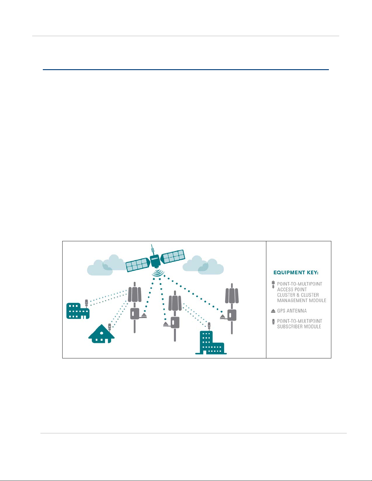
GPS synchronization
Cambium leads the wireless industry in its usage of powerful GPS synchronization
capabilities in all its PMP networks. This valuable capability dramatically reduces selfinterference in licensed or unlicensed frequency bands. GPS synchronization allows all
sites to be set to the exact same clock so netwo rk timing is very precise. As shown in the
diagram, GPS satellite timing signals reach the GPS receivers in each of the network’s
access point radios establishing a common timing reference. This allows all the access
point radios in the network — whether hundreds or thousands — to transmit at the same
time and alter natively receive as all of the subscriber modules in the network transmit at
the same time in turn. This helps prevent radio signals transmitted by an access point
transceiver to interfere with reception of a user signal by another access point transce iver,
perhaps the most onerous kind of self-interference in time-division duplex radio networks.
With GPS synchronization, you can be certai n your network can scale and grow elegantly
to serve increasing numbers of users and applications.
Figure 1 GPS Synchronization
The Navigation Satellite Timing and Ra ng ing (NAVSTAR) and Global Navigation Satellite
System (GLONASS) Global Positioning Systems (GPS) each use 24 satellites to relay
information for precise deriva tion of position and time.
The cluster management module (CMM) contains a Cambium G PS Re cei ver. Th e CMM i s a
critical element in the operation of the sy stem. At one AP cluster site or throughout an
entire wireless system, the CMM provides a GPS timing pulse to each module,
synchronizing the network transmission cycles.
PMP-0297 007v001 (January, 2017)
1-4

PMP Synchronization Solutions Us er G uide Neutralizing interference
The Oncore GPS Receiver tracks eight or more NAVSTAR or GLONASS satellites. The CMM
uses the signal from at least four of these satellites to generate a one-second interval clock
that has a rise time of 100 nsec. This clock d irectly synchronizes APs and which, in turn,
synchronize the SMs in the network.
The Oncore GPS Receiver also provides
• the latitude and longitude of the GPS antenna (co-located with the CMM)
• the number of satellites that are being tracked
• the number of satellites that are available
• the date
• the time in Universal Coordinated Time (UCT)
• the altitude of the GPS antenna
• other information that can be used to diagnose network problems.
Configuration options for TDD synchronization
Cambium PMP systems use Time Division Duplexing (TDD) - one channel alternately
transmits and receives - rather than using one channel for transmitting a n d a second
channel for receiving. To accomplish TDD, the AP must provide sync to its SMs – it must
keep them in sync. Furthermore, co-located APs must be synced together - an
unsynchronized AP that transmits during the re ceive cycle of a co-located AP can prevent
that second AP from being able to decode the si g nals from its SMs. In addition, across a
geographical area, APs that can “hear” each other benefit from using a common sync to
further reduce self-interference within the network.
For more information on each product seri es’ synchronization configuration options, refer
to the corresponding user guide, available here:
https://support.cambiumnetworks.com/files
PMP-0297 007v001 (January, 2017)
1-5
PMP Synchronization Solutions Us er G uide Neutralizing interference
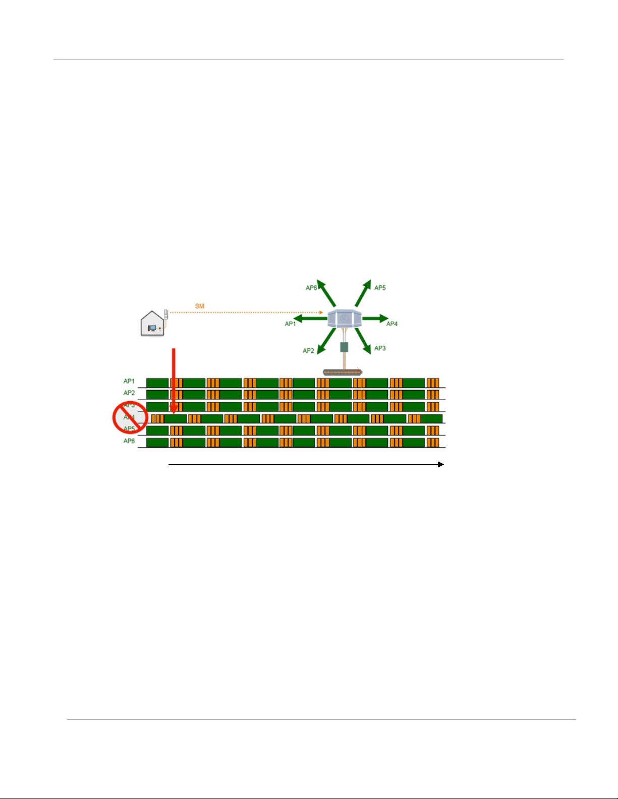
Alternative to GPS synchronization
A link can operate without
GPS sync is to configure the AP in the link to generate a sync pulse to pass to the SM.
Depending on the RF environment in which the link operates, this latter alternative may or
may not be plausible.
For example, in Figure 2, AP4
• is not synchronized with any of the other APs.
• is transmitting nearby the other APs while they are expecting to receive SM
transmissions from a maximum distance.
Figure 2 One unsynchronized AP in clus t er resulting in self-interference
GPS
sync, but cannot operate without sync. The alternative to
Time
The result is self-interference. In this scenario, the self-interference can be avoided only by
synchronizing the TDD transmit cycles of all APs that operate in the same frequency band.
An AP that is isolated by at least 5 miles (8 km) from any other equipment can generate
and pass sync pulse without GPS timing and n o t risk that interference will result from the
generated sync. In any other type of link , sync should be derived from GPS timing.
Although the embedded timing generation capability of the AP keeps a precise clock
(configuration parameter Sync S o urce set to
start the clock at the same moment in each AP of a cluster. So, the individual AP can
synchronize communications between itself and registered SMs, but cannot synchronize
itself with other modules, except by GPS timing.
PMP-0297 007v001 (January, 2017)
Generate Syn c Signal), no trigger exists to
1-6
PMP Synchronization Solutions Us er G uide Cambium’s syn c hronization solu tions
Cambium’s synchronization solutions
Cambium’s entire Point-to-Multi p oint (PMP) technology portfolio offers GPS synchronization to
limit the network’s own self-interference. The Cluster Management CMM provides Global
Positioning System (GPS) synchronization to the Access Point (AP) and all associated Subscriber
Modules (SM). Network operators have a c h oice of CMM solutions to select the option that
works best for the environment.
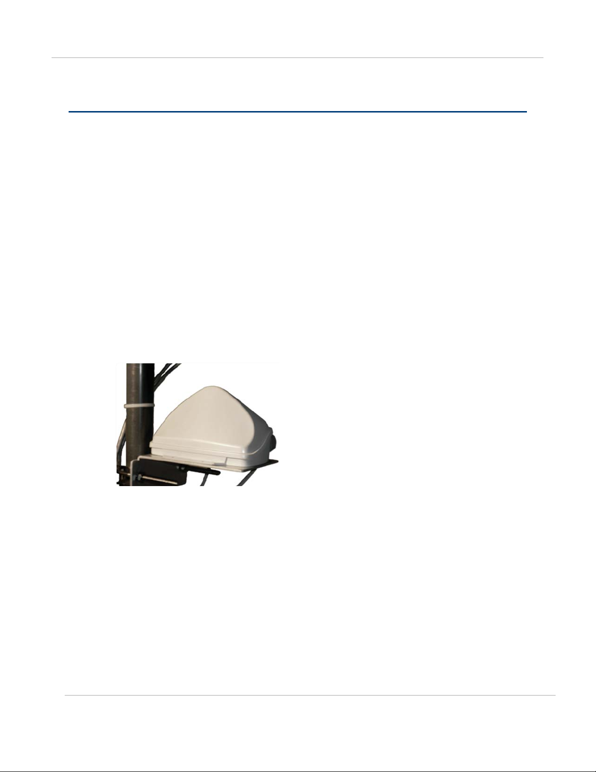
Universal GPS (UGPS)
The UGPS provides network synchronization for smaller networks where a CMM may not
be cost effective. The UGPS provides synchronization for one or two modules so that
even remote areas at the edge of the network can operate with synchronization for
improved performance. The UGPS works with all Cambium PMP radios. The UGPS has a
small footprint and is easy to deploy.
Figure 3: Universal GPS (UGPS)
PMP-0297 007v001 (January, 2017)
1-7
PMP Synchronization Solutions Us er G uide Cambium’s syn c hronization solu tions
CMM5
The CMM5 (Cluster Management Module) is the latest generation of solutions for the
distribution of TDD Sync signals and “Power-over-Ethernet (PoE)” in the field.
Figure 4: CMM5 Controller
Figure 5: CMM5 Injector
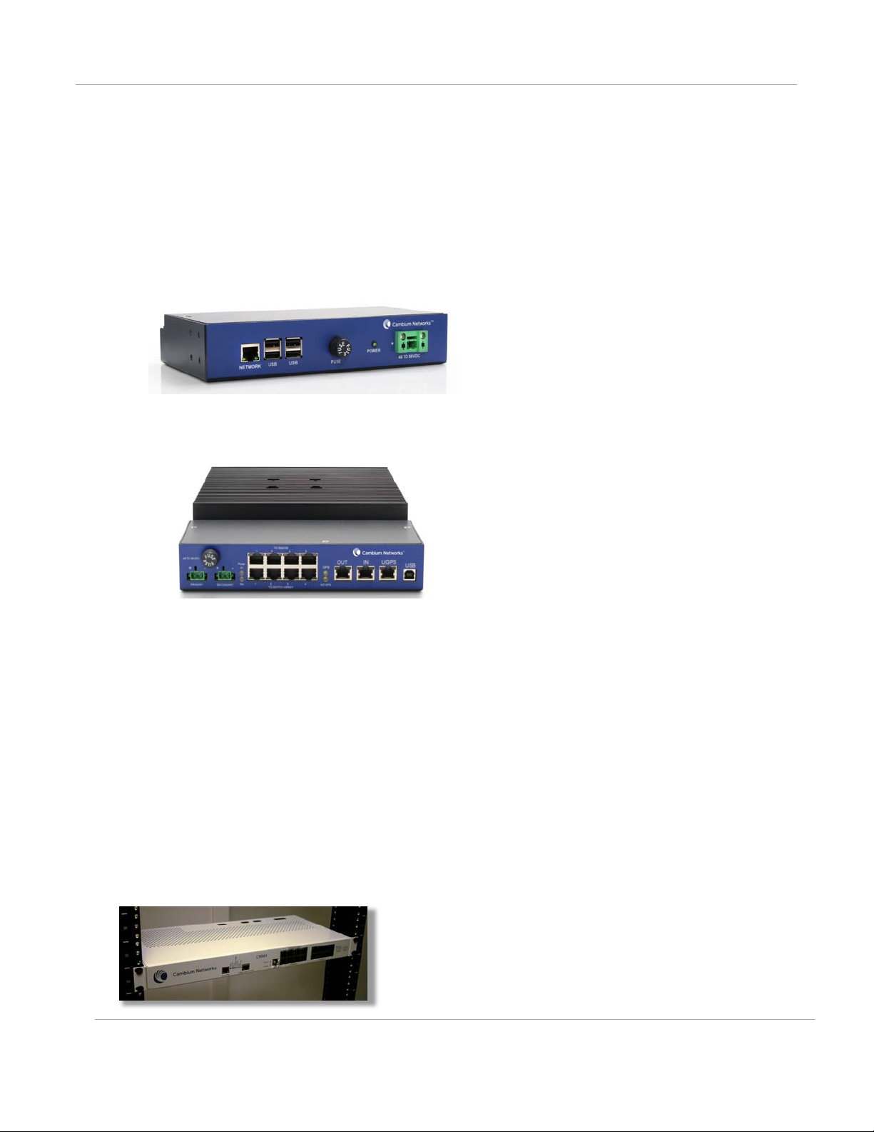
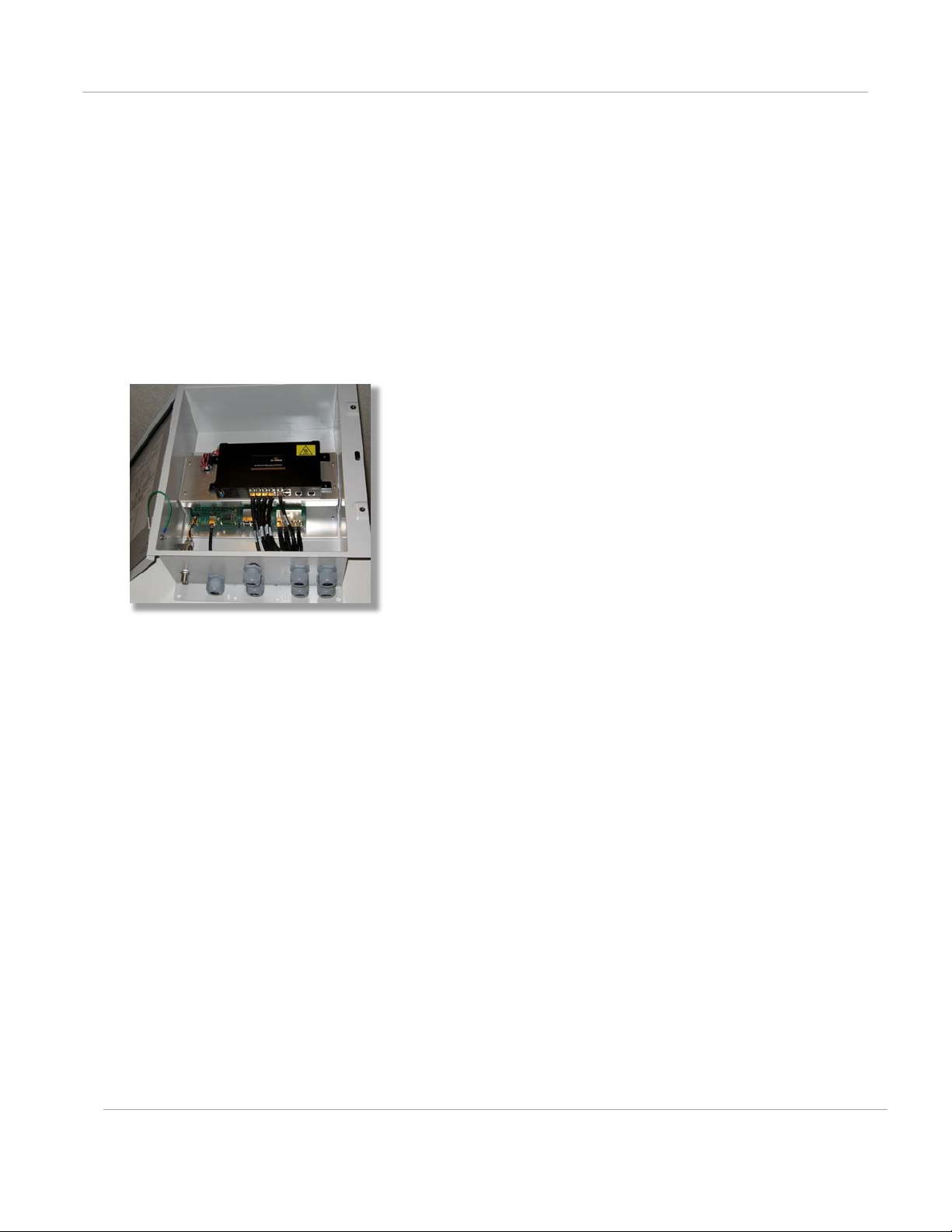
CMM4 (Rack
The cluster management module (CMM) is the heart of the Cambium system’s
synchronization capability, which allows network operators to reuse frequencies and add
capacity while ensuring consistency in the quality of service to customers. For operators
who prefer indoor CMM mounting, Cambium offers the Rack-Mounted Cluster
Management Module 4. The unit is designed to be mounted on to a standard 19-inch
telecommunications rack and to allow the Cambium CMM4 to be co-located with other
telecommunications equipment.
Mount)
Figure 6: CMM4 Rack Mount
PMP-0297 007v001 (January, 2017)
1-8
PMP Synchronization Solutions Us er G uide Cambium’s syn c hronization solu tions
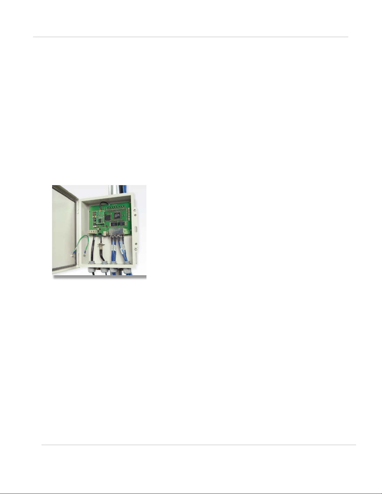
CMM4
Designed to deliver consistent and reliable wireless broadband service, the PMP system
gracefully scales to support large deployments. The cluster management module is the heart of
the system’s synchronization capabili ty which allows network operators to re-use frequencies
and add capacity while ensuring consistency in the quality of service to customers. As a result,
subscribers can experience carrier-grade service even those at the outer edge of the network.
Figure 7: Cabinet (with switch)
(Cabinet
with
switch)
CMM4
This CMM includes all of the functional ity listed above but there is no switch included. This
provides the network operator the flexi b ility to use the switch of their choice with the power and
synchronization capabilities of the CMM4.
(Cabinet
without
switch)
PMP-0297 007v001 (January, 2017)
1-9
PMP Synchronization Solutions Us er G uide Cambium’s syn c hronization solu tions
CMMmicro (CMM3) – Product is End of Life and no longer available for new shipments
The Cluster Management Module 3 (CMM3), also known as the CMMmicro, allows network
operators to reduce the time and labor cost of system installation and maintenance in AP
Clusters. This management module reduces cabling between system modules and provides
reliable network synchronization. There is only one cable going from the CMM3 to each module
carrying the Ethernet connection, synchronizatio n pulse and GPS data.
Figure 8: CMMmicro (CMM3)
PMP-0297 007v001 (January, 2017)
1-10

PMP Synchronization Solutions Us er G uide Cambium’s synchronization solutions
Chapter 2: Cambium Cluster Management
Module (CMM5)
The CMM5 consists of 4 subsystems, described in the following sections:
• CMM5 Controller Module
• CMM5 Injector (29 volt and 56 volt versions)
• Power supply(s) (240/600 watt)
• uGPS
PMP-0297 007v001 (January, 2017)
2-11

PMP Synchronization Solutions Us er G uide Product Overview
Scenario
Equipment Needed
Features
Product Overview
The CMM5 (Cluster Management Module) is the latest generation of solutions for the
distribution of TDD Sync signals and “Power-over-Ethernet (PoE)” in the field. The CMM5 is
a modular design with individual 4-port power inj ectors and an optional controller used for
remote management.
Key features of the CMM5 include:
• Support for Gigabit Ethernet (1000BaseT)
• Modular and scalable from 4 ports to 32 ports
• Direct +/- 48VDC input (optional AC/DC power supplies are available from Cambium
Networks)
• Uses Cambium Networks uGPS for a synchronizati on source
• Dual resilent power inputs
• Rack mountable
• Secure remote managem ent when used with the optional CMM5 Controller Module
• Support for PMP 450m (cnMedusa™)
• Future support for integration into (cnMedusa™) for cloud or NOC-based
management
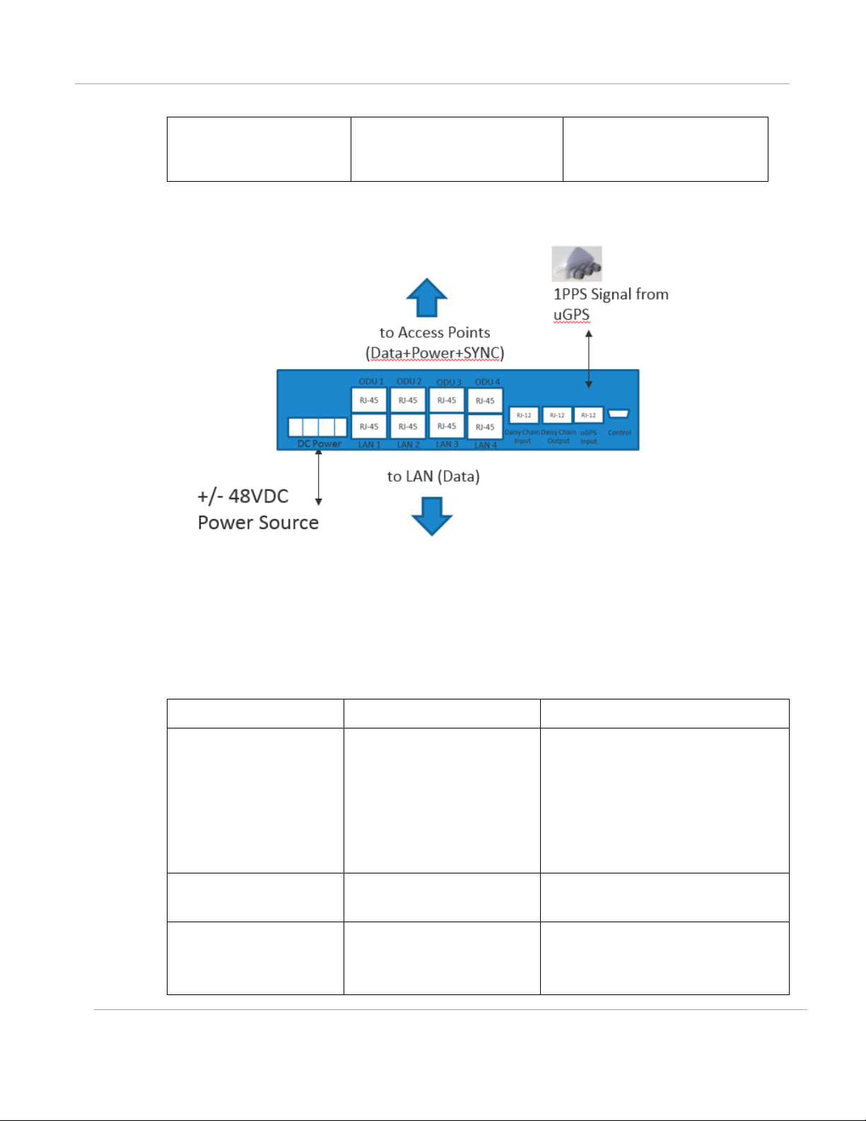
Cluster Management: Scenario 1
The following is a CMM5 Cluster Management scenario using four PMP 450i Access Points.
Four PMP 450i Access
Points
56 Volt Injector • Gigabit Ethernet
• Local Management
Interface
• +/- 48VDC Input
• Broad Device
Support
PMP-0297 007v001 (January, 2017)
• Rack Mountable
• 48 VDC Available uGPS --------------------------------------
2-12
PMP Synchronization Solutions Us er G uide Product Overview
Scenario
Equipment Needed
Features
• No management
or resiliance
required
Figure 9: Cluster Management: Scenario 1
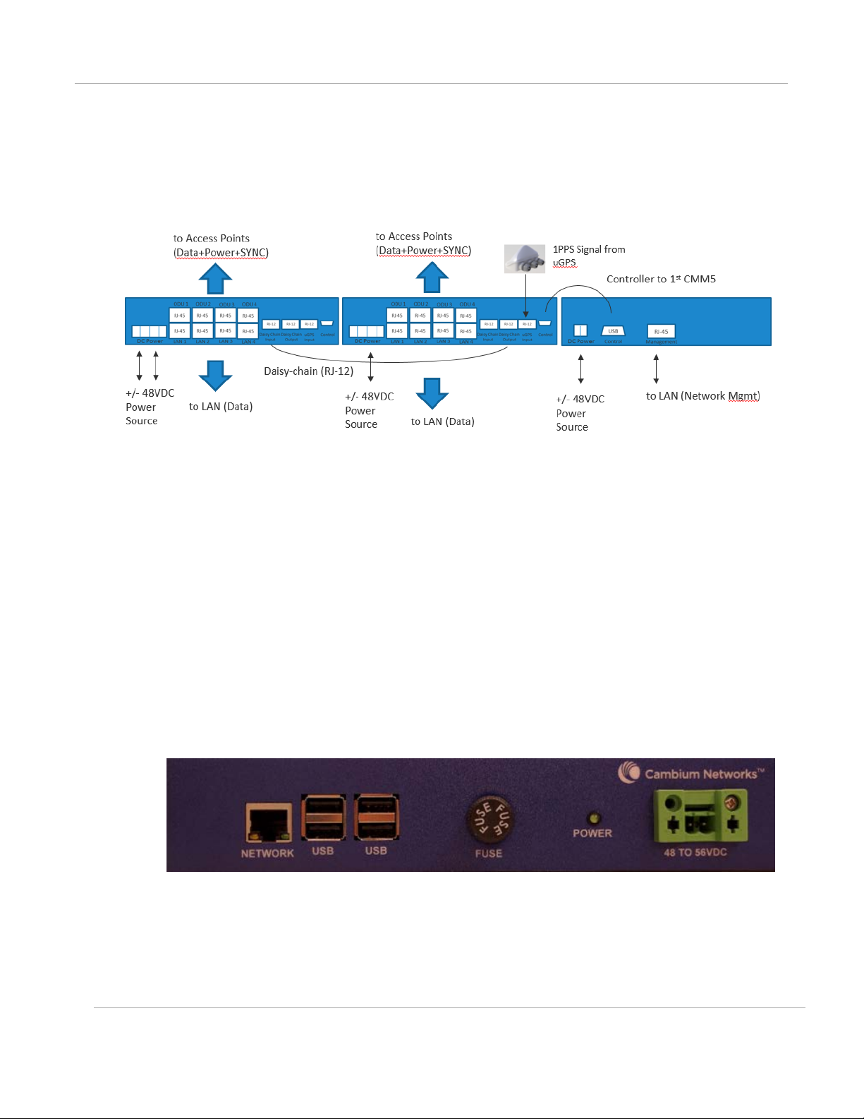
Cluster Management: Scenario 2
The following is a CMM5 Cluster Management scenario using four PMP 450i Access Points
and four PMP 450 Access Points.
Four PMP 450i Access
Points
Four PMP 450 Access
Points
AC only environments Two AC-to-48VDC Power
Management required.
Resilence required.
• 56 Volt Injector
• 29 Volt Injector
• 1 CMM5 Controller
• One uGPS
Supplies
-------------------------------------- • Secure, Remote
• Gigabit Ethernet support
• Local Management
Interface
• +/- 48VDC Input
• Broad Device Support
• Rack Mountable
• Resilent power sources
Management (https)
• Scalable to 32 devices
PMP-0297 007v001 (January, 2017)
2-13
PMP Synchronization Solutions Us er G uide Product Overview
Figure 10: Cluster Management: Scenario 2
CMM5 Controller Module
The major features of the CMM5 Controller Module are:
• Auto-detect/control up to 8 Power Injectors
• Monitor SYNC/Power/GPS status
• Manage (up/down ports)
• Web (HTTPS) and SNMPv2/v3 management (SNMP on roadmap)
• 1U/ half-width rack-mount
Figure 11: Controller Module
PMP-0297 007v001 (January, 2017)
2-14
PMP Synchronization Solutions Us er G uide Product Overview
Product
Power/Injector Model
Sync
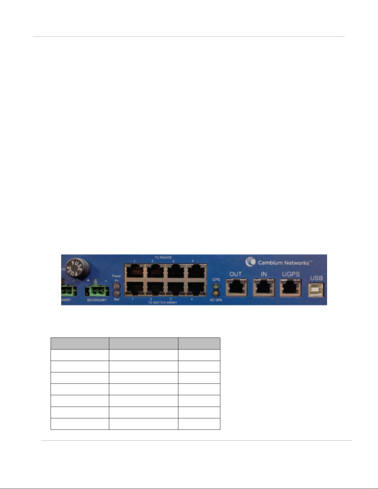
CMM5 Injector Module
The CMM5 Injector Module has the following features:
• Stand-alone mode or used with controller for mgmt.
• +/- 48VDC input with green/amber LED’s for status
• Injects SYNC pulse from uGPS
• 2U / half-width rack-mount
Note that there are two different versions of the injector module (56V and 29V). You must select
the correct injector for the types of radios that you will be powering. In both cases the injectors use
the same input power supplies or can be powered with +/- 48VDC. The output power is different
and the type of SYNC signal used is different between the two types of injectors.
Systems can have 29V and 56V injectors deployed alongside each other.
Figure 12: Injector Module
CMM5 Injector Compatibility Matrix
PMP/PTP 450i Yes/56V Yes
PMP 450m Yes/56V Yes
ePMP 2000 Yes/56V Roadmap
PTP 670 Yes/56V Roadmap
PTP 700 Yes/56V Roadmap
PMP 450/PTP 450 Yes/29V Yes
PMP 100/PTP 100 Yes/29V Yes
PMP-0297 007v001 (January, 2017)
2-15

PMP Synchronization Solutions Us er G uide Product Overview
CMM5 Power and Sync Injector 56 Volts
Model Number
C000000L556A
Data Interface
Surge Suppresion
Lightning Suppression for each “ To Radios” RJ45
Port
Power
Output Power: 0 - 90 Watts per channel
Cabinet Temperature
-40° C to +55°C (-40° F to +131° F), 90% humidity,
condensing
Physical
Dimensions
8.85” W x 15.75” D x 1.65” H (225mm x 400mm x
42mm)
Unit Weight
6.6 pounds (3kg)
Power Interface Terminals
(Power supplies sold
separately)
CMM5 Specifications
The following table provides specifications for the CMM5 Power & Sync Injector (56 Volts).
4 each RJ45 Gigabit Powered output ports “To
Radios”
4 each RJ45 Gigabit Data input ports “To Switch
Array”
1 each GPS timing port (RJ-12)
1 each CMM5 USB Serial port for local
administration
1 each RJ12 Daisy Chain port “IN”
1 each RJ12 Daisy Chain port “OUT”
Input Voltage: + or - 48 VDC
Input Power Consumption: 400 watts
Output Voltage: + or - 55 VDC
Output Current: 0 - 1.8A per channel
Max Distance from Managed Radios: 328 cable
feet (100m)
Max Distance to GPS Antenna: 100 cable feet
(30.5m)
2 Power input ports for 48 VDC Power
PMP-0297 007v001 (January, 2017)
2-16
 Loading...