

Cambium Networks ePMP 1000 Ordering Manual
1000 Ordering Guide
ePMP 1000 CONNECTORIZED RADIO WITH SYNCePMP 1000 INTEGRATED RADIO
CN ePMP OG 09242013

Ordering Guide: 1000 Integrated Radio & 1000 Connectorized Radio with Sync
CAMBIUM NETWORKS
1.0 Introduction 3
2.0 Ordering Connectorized Synchronized Radios 6
2.1 Connectorized Synchronized Radios 6
2.2 AP Sector Antenna Options 7
2.3 Power Supply for Connectorized, Synchronized Radio 7
2.4 Surge Suppression 8
2.5 GPS Synchronization 8
2.6 Extended Warranties 9
3.0 Ordering Integrated Radios 10
3.1 Integrated Radio Modules 10
3.2 Power Supply for Integrated Radio 11
3.3 Surge Suppression 11
3.4 Cabling and Accessories 12
3.5 Extended Warranties 12
4.0 AP and SM Installation Examples 13
4.1 ePMP Radio Mounted an a Tower 13
4.2 ePMP Radio on a Residential or Commercial Building 14
4.3 ePMP Radio on a Rooftop 15
4.4 ePMP Radio Module Grounding and Protection 16
CN ePMP OG 09242013
2

Ordering Guide: 1000 Integrated Radio & 1000 Connectorized Radio with Sync
CAMBIUM NETWORKS
1 Introduction
THIS ORDERING GUIDE covers the Cambium ePMP Platform. It is intended to provide a
structured guide to ordering a solution with any accessories and ancillary items
for a successful installation.
The key steps involved in planning and ordering your system are:
REGULATORY PLANNING: To begin, you need to contact the applicable radio regulator in
1
2
your area to identify any restrictions or limitation imposed on radio equipment operat-
ing in your planned RF band and to determine whether or not you need to register your
PMP network. As the user of the radio equipment, it is your responsibility to ensure that
your system complies with any regulatory guidelines imposed by the local regulator.
SITE PLANNING: We recommend that you complete a site survey to identify the many
considerations critical for successful site selection such as the availability of tower or
rooftop space, the location of the grounding system, best positioning of the APs, SMs
and BHs, aesthetics and other permission-based issues, and maximum cable lengths
required for your deployment.
3
4
5
LINK AND SECTOR PLANNING: You need to determine link and sector-planning factors
such as path obstructions, risk of interference, path and link loss, maximum power levels
permitted, and coverage requirements.
SPECTRUM ANALYSIS: One of the most important elements in your planning process is the
analysis of spectrum usage and signal strength needed to occupy the spectrum you are
planning to use. For a PMP system, you need to plan your sector coverage to determine
how many APs will be needed and what sector size will be required to provide adequate
coverage for the deployment. For PTP links you need to determine whether there is
available spectrum to accomplish your desired goal.
PREPARING AN EPMP ORDER: Once you have identified all the regulatory requirements
and planned the site, link, sector coverage and spectrum requirements, you are ready to
compile your order. This Ordering Guide provides the part numbers, product descrip-
tions, instructions, and resources to help you complete an ePMP order.
CN ePMP OG 09242013
3
Ordering Guide: 1000 Integrated Radio & 1000 Connectorized Radio with Sync
CAMBIUM NETWORKS
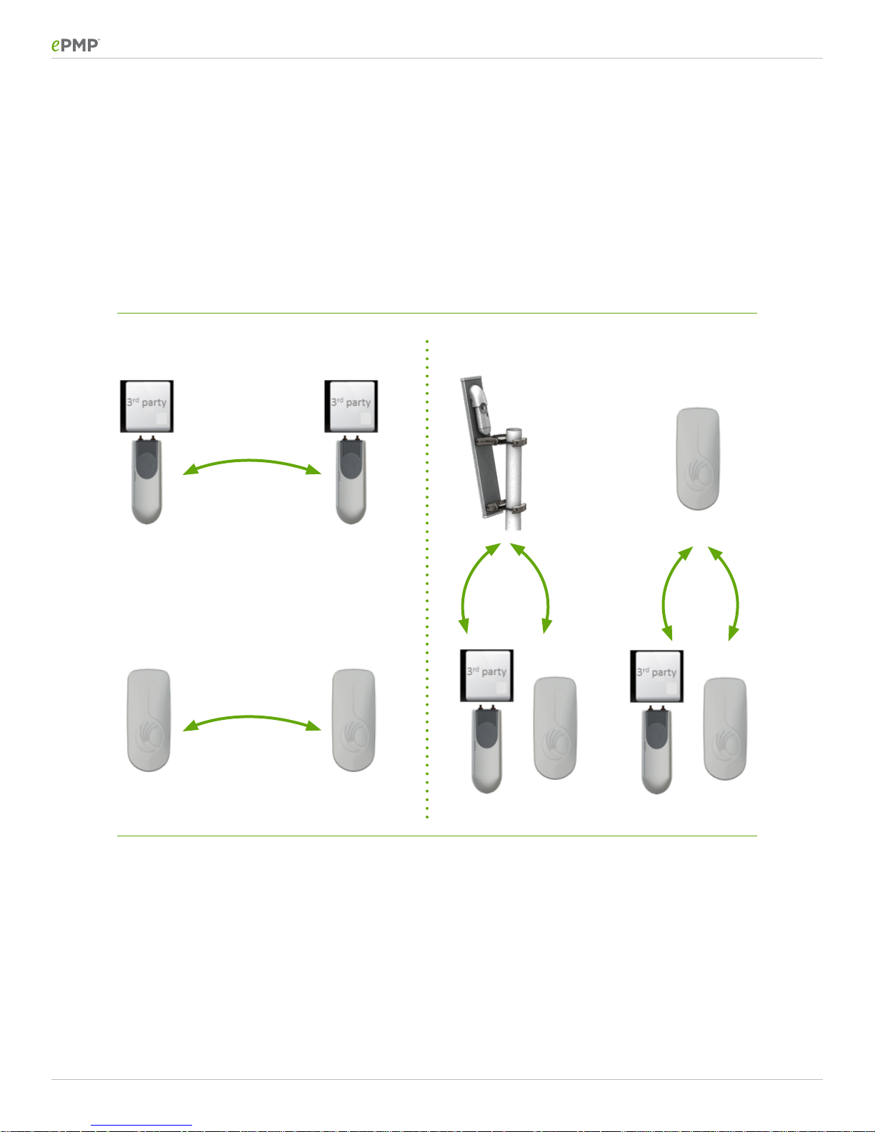
Deployment Configurations
The ePMP Solution is very versatile. Each of the radio units can be configured to be an Access Point,
a Subscriber Module or a Point to Point radio. When the connectorized radio is combined with an
external antenna, a wide variety of configurations can be supported with the solution.
The figure below illustrates the dierent configurations that can be deployed.
SYNCHRONIZED &
UNSYNCHRONIZED
PTP LINKS
UNSYNCHRONIZED
PTP LINKS
SYNCHRONIZED &
UNSYNCHRONIZED
PMP
CN ePMP OG 09242013
4

Ordering Guide: 1000 Integrated Radio & 1000 Connectorized Radio with Sync
When you are ready to prepare your order, the following equipment components can be selected
for an ePMP network.
ePMP System Components
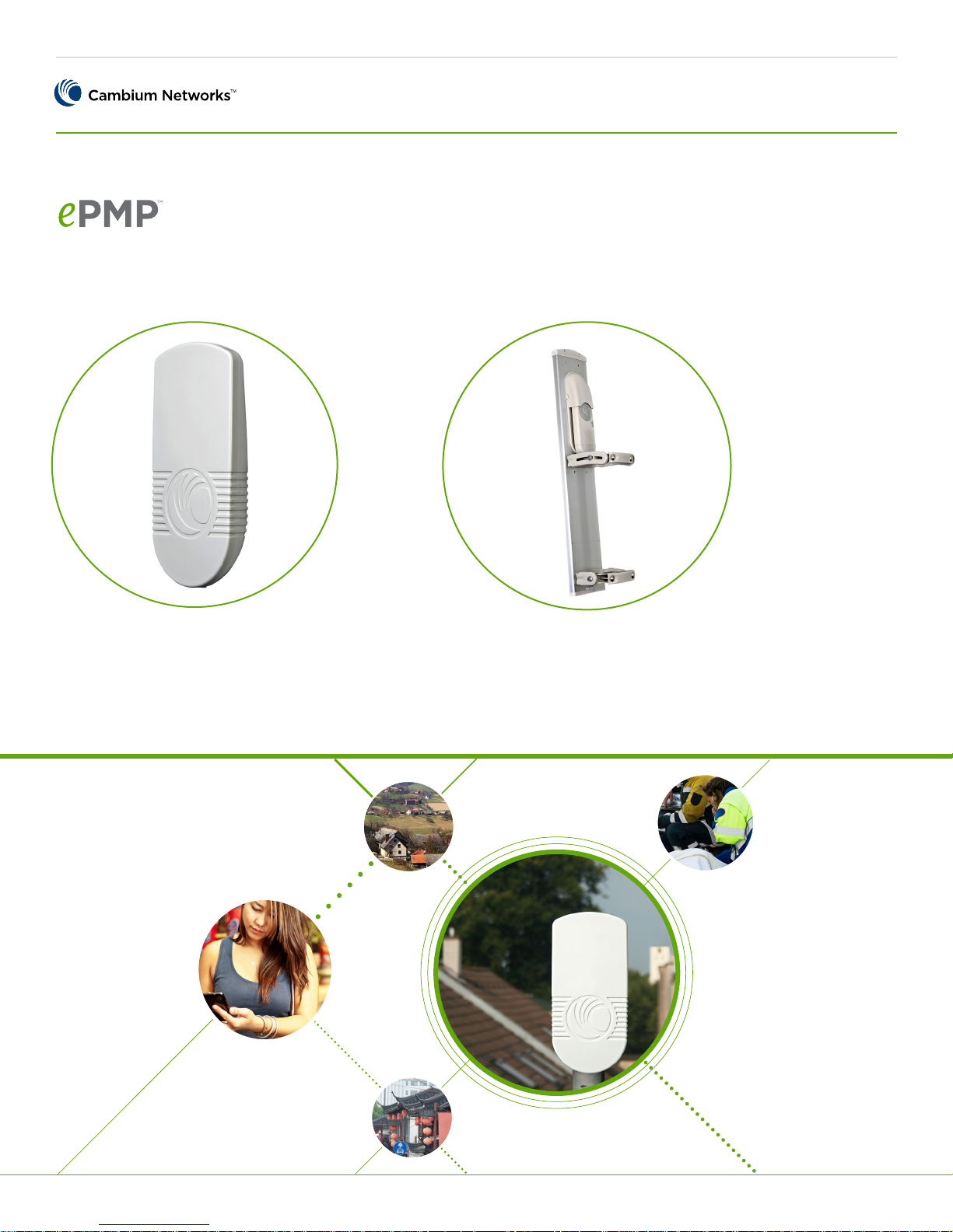
ePMP Connectorized Radio with Sync ePMP Integrated Radio
CAMBIUM NETWORKS
IF CONFIGURED AS AN ACCESS POINT:
Determine the Number of Radios Required based on the
coverage area and the sector configuration (90 degree or 120
degree) selected
IF CONFIGURED AS PTP RADIO:
Determine the Number of Radios Required based on the number of links needed
POWER SUPPLY:
A 30 V Power Supply which allows for Gigabit Ethernet operation is included with the Radio
Alternatively, the Radio can be powered by the Cambium
CMM3 and CMM4 or a third party 802.3af compliant powering
device
ANTENNA:
4-sector dual polarity (H+V)
3-sector dual polarity (H+V)
Alternative configuration (verify regulations prior to purchase)
IF CONFIGURED AS A SUBSCRIBER MODULE:
Determine the Number of SMs required
IF CONFIGURED AS AN ACCESS POINT:
Determine the Number of Radios Required based on the coverage area. The integrated antenna has a beam width of approximately 24 degrees
IF CONFIGURED AS PTP RADIO:
Determine the Number of Radios Required based on the number of links needed
POWER SUPPLY:
A 30 V Power Supply which allows for Fast Ethernet operation
is included with the Radio
Alternatively, the Radio can be powered by any of the PMP100
or PMP4X0 SM Power Supplies
ANTENNA:
The ePMP Integrated radio includes a 13 dBi, 24 degree antenna
SURGE SUPPRESSOR:
The Connectorized, Synchronized radios include built-in surge
suppression – no external suppression is required at the device
SHOULD ADD EXTERNAL UNITS AT:
Cable entrance point leading to Building entrance
On the bottom of the tower/pole near the grounding bar
If the Ethernet connection of the Radio is to be operated in
10/100 Mbps mode, then the 600SSH Surge suppressor can
be utilized. Otherwise a 3rd party gigabit Ethernet compatible
surge suppressor should be used. Such a surge suppressor
(Models # AL-CAT6JW and AL-CAT6HPJW) is available from
L-Com.
CABLING AND ACCESSORIES:
Cat 5e cables
Grounding cables
Connectors
EXTENDED WARRANTY:
One additional year of coverage
Two additional years of coverage
Four additional years of coverage
SURGE SUPPRESSOR:
The Integrated radios include built-in surge suppression – no
external suppression is required at the device
SHOULD ADD EXTERNAL UNITS (600SSH) AT:
–Cable entrance point leading to Building entrance
–On the bottom of the tower/pole near the grounding bar (if
deployed on a tower)
CABLING AND ACCESSORIES:
Cat 5e cables
Grounding cables
Connectors
EXTENDED WARRANTY:
One additional year of coverage
Two additional years of coverage
Four additional years of coverage
CN ePMP OG 09242013
5
Ordering Guide: 1000 Integrated Radio & 1000 Connectorized Radio with Sync
CAMBIUM NETWORKS
2 Ordering Connectorized Radio with Sync
2.1 Connectorized Synchronized Radios
Each module contains both radio and networking electronics supplied in a connectorized configura-
tion for use with an external antenna. Connectorized modules with external antennas are designed to
cope with more dicult radio conditions. When configured as an Access Point and operating in a 20
MHz channel configuration, each connectorized, synchronized radio module can provide a capacity
of up to 100 Mbps. As an Access Point, the module can support up to 120 SMs. For an optimal per-
forming system, it is recommended that no more than 60 SMs be connected to one Access Point.
ePMP AP Radio Unit ePMP AP Radio Antenna
Part Number Description
C050900A011A
C058900A112A
C050900A013A
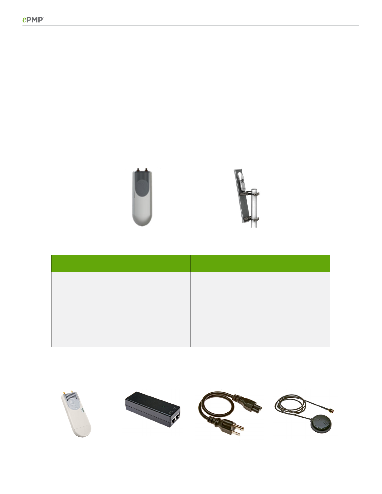
The images below shows what is included in the box when a Connectorized Radio is purchased:
GPS Synchronized Connectorized Radio
ePMP 1000: 5 GHz Connectorized Radio with
Sync (ROW)
ePMP 1000: 5 GHz Connectorized Radio with
Sync (FCC)
ePMP 1000: 5 GHz Connectorized Radio with
Sync (EU)
Radio Module
CN ePMP OG 09242013
Power Supply
Power Cord
(Us/Fcc Model Only)
GPS Antenna
6
 Loading...