

Page 1

33F
Cambium
PMP/PTP 450(i) Series
User Guide
System Release 14.1
pass
Page 2

pmp-0957_001v001 (October 2015)
Accuracy
While reasonable efforts have been made to assure the accuracy of this document, Cambium Networks
assumes no liability resulting from any inaccuracies or omissions in this document, or from use of the
information obtained herein. Cambium reserves the right to make changes to any products described
herein to improve reliability, function, or design, and reserves the right to revise this document and to
make changes from time to time in content hereof with no obligation to notify any person of revisions
or changes. Cambium does not assume any liability arising out of the application or use of any
product, software, or circuit described herein; neither does it convey license under its patent rights or
the rights of others. It is possible that this publication may contain references to, or information about
Cambium products (machines and programs), programming, or services that are not announced in
your country. Such references or information must not be construed to mean that Cambium intends to
announce such Cambium products, programming, or services in your country.
Copyrights
This document, Cambium products, and 3rd Party software products described in this document may
include or describe copyrighted Cambium and other 3rd Party supplied computer programs stored in
semiconductor memories or other media. Laws in the United States and other countries preserve for
Cambium, its licensors, and other 3rd Party supplied software certain exclusive rights for copyrighted
material, including the exclusive right to copy, reproduce in any form, distribute and make derivative
works of the copyrighted material. Accordingly, any copyrighted material of Cambium, its licensors, or
the 3rd Party software supplied material contained in the Cambium products described in this
document may not be copied, reproduced, reverse engineered, distributed, merged or modified in any
manner without the express written permission of Cambium. Furthermore, the purchase of Cambium
products shall not be deemed to grant either directly or by implication, estoppel, or otherwise, any
license under the copyrights, patents or patent applications of Cambium or other 3rd Party supplied
software, except for the normal non-exclusive, royalty free license to use that arises by operation of
law in the sale of a product.
Restrictions
Software and documentation are copyrighted materials. Making unauthorized copies is prohibited by
law. No part of the software or documentation may be reproduced, transmitted, transcribed, stored in a
retrieval system, or translated into any language or computer language, in any form or by any means,
without prior written permission of Cambium.
License Agreements
The software described in this document is the property of Cambium and its licensors. It is furnished
by express license agreement only and may be used only in accordance with the terms of such an
agreement.
High Risk Materials
Cambium and its supplier(s) specifically disclaim any express or implied warranty of fitness for any
high risk activities or uses of its products including, but not limited to, the operation of nuclear
facilities, aircraft navigation or aircraft communication systems, air traffic control, life support, or
weapons systems (“High Risk Use”). Any High Risk is unauthorized, is made at your own risk and you
shall be responsible for any and all losses, damage or claims arising out of any High Risk Use.
© 2015 Cambium Networks Limited. All Rights Reserved.
Page 3

Page i
Contents
About This User Guide ............................................................................................ 1#
Contacting Cambium Networks ................................................................................................... 1#
Purpose ........................................................................................................................................... 2#
Cross references ............................................................................................................................ 2#
Feedback ......................................................................................................................................... 2#
Important regulatory information ....................................................................................................... 3#
Application firmware ..................................................................................................................... 3#
USA specific information .............................................................................................................. 3#
Canada specific information ......................................................................................................... 4#
Renseignements specifiques au Canada ..................................................................................... 5#
EU Declaration of Conformity ....................................................................................................... 6#
Specific expertise and training for professional installers ......................................................... 6#
Ethernet networking skills ............................................................................................................. 6#
Lightning protection ...................................................................................................................... 7#
Training .......................................................................................................................................... 7#
Problems and warranty ........................................................................................................................ 8#
Reporting problems ....................................................................................................................... 8#
Repair and service ......................................................................................................................... 8#
Hardware warranty ........................................................................................................................ 8#
Security advice ..................................................................................................................................... 9#
Warnings, cautions, and notes .......................................................................................................... 10#
Warnings ...................................................................................................................................... 10#
Cautions ........................................................................................................................................ 10#
Notes ............................................................................................................................................. 10#
Caring for the environment ............................................................................................................... 11#
In EU countries ............................................................................................................................. 11#
In non-EU countries ..................................................................................................................... 11#
Chapter 1:# Product description ........................................................................... 1-1#
Overview of the PMP/PTP 450(i) Series .......................................................................................... 1-2#
Purpose ....................................................................................................................................... 1-2#
PMP/PTP 450i Series .................................................................................................................. 1-2#
PMP/PTP 450 Series ................................................................................................................... 1-5#
Supported interoperability for 450i/450/430 platforms .......................................................... 1-8#
Typical deployment ................................................................................................................... 1-9#
Product variants ....................................................................................................................... 1-10#
Wireless operation ......................................................................................................................... 1-12#
Time division duplexing .......................................................................................................... 1-12#
Page 4

Contents
Page ii
MIMO ........................................................................................................................................ 1-15#
Encryption ................................................................................................................................ 1-15#
System management ..................................................................................................................... 1-16#
Management agent ................................................................................................................. 1-16#
Web server ............................................................................................................................... 1-16#
Remote Authentication Dial-in User Service (RADIUS) ........................................................ 1-18#
SNMP ........................................................................................................................................ 1-18#
Network Time Protocol (NTP) ................................................................................................. 1-18#
Wireless Manager (WM) ......................................................................................................... 1-19#
Radio recovery mode – Radio Recovery Console / Default Mode (fka Default Plug) ......... 1-20#
Chapter 2:# System hardware .............................................................................. 2-1 #
System Components ........................................................................................................................ 2-2#
Point-to-Multipoint (PMP) ......................................................................................................... 2-2#
Backhaul (PTP) ........................................................................................................................... 2-5#
PMP/PTP 450(i) interfaces ......................................................................................................... 2-7#
Diagnostic LEDs ....................................................................................................................... 2-11#
ODU part numbers .................................................................................................................. 2-14#
Power supply options .............................................................................................................. 2-20#
ODU mounting brackets & accessories ................................................................................. 2-24#
Lightning protection ................................................................................................................ 2-25#
Cabling and lightning protection .................................................................................................. 2-26#
ODU interfaces – PMP/PTP 450i .............................................................................................. 2-26#
Ethernet standards and cable lengths ................................................................................... 2-27#
Outdoor copper Cat5e Ethernet cable .................................................................................... 2-29#
Main Ethernet port ................................................................................................................... 2-30#
Aux port .................................................................................................................................... 2-30#
Cable grounding kit ................................................................................................................. 2-32#
Lightning protection unit (LPU) and grounding kit ............................................................... 2-32#
Antennas and antenna cabling ...................................................................................................... 2-34#
Antenna requirements ............................................................................................................ 2-34#
Supported external AP antennas ........................................................................................... 2-34#
Supported external SM antennas .......................................................................................... 2-34#
RF cable and connectors ......................................................................................................... 2-35#
Antenna accessories ................................................................................................................ 2-35#
RJ45 connectors and spare glands ........................................................................................ 2-35#
GPS synchronization ...................................................................................................................... 2-37#
GPS synchronization description ........................................................................................... 2-37#
Universal GPS (UGPS) ............................................................................................................ 2-37#
CMM4 (Rack
Mount)
............................................................................................................... 2-37#
CMM4
(Cabinet
with
switch)
................................................................................................ 2-40#
CMM4
(Cabinet
without
switch)
........................................................................................... 2-40#
CMM4/CMMmicro ................................................................................................................... 2-40#
Ordering the components .............................................................................................................. 2-42#
Page 5

Contents
Page iii
Chapter 3:# System planning ............................................................................... 3-1#
Typical deployment .......................................................................................................................... 3-2#
ODU with PoE interface to PSU ................................................................................................ 3-2#
Site planning ..................................................................................................................................... 3-7#
Site selection for PMP/PTP radios ............................................................................................ 3-7#
Calculated distances and power compliance margin ............................................................. 3-7#
Power supply site selection ...................................................................................................... 3-8#
Maximum cable lengths ............................................................................................................ 3-8#
Grounding and lightning protection ........................................................................................ 3-8#
ODU and external antenna location ....................................................................................... 3-10#
ODU ambient temperature limits ........................................................................................... 3-10#
ODU wind loading ................................................................................................................... 3-11#
Drop cable grounding points .................................................................................................. 3-12#
LPU location ............................................................................................................................. 3-13#
Radio Frequency planning ............................................................................................................. 3-14#
Regulatory limits ...................................................................................................................... 3-14#
Conforming to the limits ......................................................................................................... 3-14#
Available spectrum .................................................................................................................. 3-15#
Analyzing the RF Environment ............................................................................................... 3-15#
Channel bandwidth ................................................................................................................. 3-15#
Anticipating Reflection of Radio Waves ................................................................................ 3-16#
Obstructions in the Fresnel Zone ........................................................................................... 3-16#
Planning for co-location .......................................................................................................... 3-16#
Multiple OFDM Access Point Clusters ................................................................................... 3-17#
Link planning .................................................................................................................................. 3-19#
Range and obstacles ............................................................................................................... 3-19#
Path loss ................................................................................................................................... 3-19#
Calculating Link Loss ............................................................................................................... 3-20#
Calculating Rx Signal Level .................................................................................................... 3-20#
Calculating Fade Margin ......................................................................................................... 3-21#
Adaptive modulation ............................................................................................................... 3-21#
Planning for connectorized units .................................................................................................. 3-22#
When to install connectorized units ....................................................................................... 3-22#
Choosing external antennas ................................................................................................... 3-22#
Calculating RF cable length (5.8 GHz FCC only) .................................................................... 3-22#
Data network planning ................................................................................................................... 3-24#
Understanding addresses ....................................................................................................... 3-24#
Dynamic or static addressing ................................................................................................. 3-24#
DNS Client ................................................................................................................................ 3-25#
Network Address Translation (NAT) ...................................................................................... 3-25#
Developing an IP addressing scheme .................................................................................... 3-26#
Address Resolution Protocol .................................................................................................. 3-26#
Allocating subnets ................................................................................................................... 3-27#
Page 6

Contents
Page iv
Selecting non-routable IP addresses ..................................................................................... 3-27#
Translation bridging ................................................................................................................ 3-28#
Engineering VLANs ................................................................................................................. 3-28#
Network management planning ................................................................................................... 3-32#
Planning for SNMP operation ................................................................................................. 3-32#
Enabling SNMP ........................................................................................................................ 3-32#
Security planning ........................................................................................................................... 3-33#
Isolating AP/BHM from the Internet ....................................................................................... 3-33#
Encrypting radio transmissions .............................................................................................. 3-33#
Planning for HTTPS operation ................................................................................................ 3-34#
Planning for SNMPv3 operation ............................................................................................. 3-34#
Managing module access by passwords ............................................................................... 3-35#
Planning for RADIUS operation .............................................................................................. 3-36#
Filtering protocols and ports .................................................................................................. 3-36#
Encrypting downlink broadcasts ............................................................................................ 3-40#
Isolating SMs in PMP .............................................................................................................. 3-40#
Filtering management through Ethernet ............................................................................... 3-40#
Allowing management from only specified IP addresses .................................................... 3-41#
Configuring management IP by DHCP ................................................................................... 3-41#
Controlling PPPoE PADI Downlink Forwarding ..................................................................... 3-41#
Chapter 4:# Legal and regulatory information ...................................................... 4-1#
Cambium Networks end user license agreement .......................................................................... 4-2#
Definitions .................................................................................................................................. 4-2#
Acceptance of this agreement .................................................................................................. 4-2#
Grant of license .......................................................................................................................... 4-2#
Conditions of use ....................................................................................................................... 4-3#
Title and restrictions .................................................................................................................. 4-4#
Confidentiality ............................................................................................................................ 4-4#
Right to use Cambium’s name ................................................................................................. 4-5#
Transfer ...................................................................................................................................... 4-5#
Updates ...................................................................................................................................... 4-5#
Maintenance ............................................................................................................................... 4-5#
Disclaimer ................................................................................................................................... 4-6#
Limitation of liability .................................................................................................................. 4-6#
U.S. government ........................................................................................................................ 4-6#
Term of license .......................................................................................................................... 4-7#
Governing law ............................................................................................................................ 4-7#
Assignment ................................................................................................................................ 4-7#
Survival of provisions ............................................................................................................... 4-7#
Entire agreement ....................................................................................................................... 4-7#
Third party software .................................................................................................................. 4-7#
Compliance with safety standards ................................................................................................ 4-22#
Electrical safety compliance ................................................................................................... 4-22#
Page 7

Contents
Page v
Electromagnetic compatibility (EMC) compliance ................................................................ 4-22#
Human exposure to radio frequency energy ........................................................................ 4-22#
Compliance with radio regulations ............................................................................................... 4-28#
Type approvals ........................................................................................................................ 4-29#
Brazil specific information ...................................................................................................... 4-29#
Australia Notification ............................................................................................................... 4-30#
Regulatory Requirements for CEPT Member States (www.cept.org) ................................. 4-30#
Chapter 5:# Preparing for installation .................................................................. 5-1 #
Safety ................................................................................................................................................. 5-2#
Power lines ................................................................................................................................. 5-2#
Working at heights .................................................................................................................... 5-2#
Power supply ............................................................................................................................. 5-2#
Grounding and protective earth ............................................................................................... 5-2#
Powering down before servicing ............................................................................................. 5-2#
Primary disconnect device ........................................................................................................ 5-3#
External cables ........................................................................................................................... 5-3#
RF exposure near the antenna .................................................................................................. 5-3#
Minimum separation distances ................................................................................................ 5-3#
Grounding and lightning protection requirements ................................................................ 5-3#
Grounding cable installation methods .................................................................................... 5-3#
Siting ODUs and antennas ........................................................................................................ 5-4#
Thermal Safety ........................................................................................................................... 5-4#
Preparing for installation ................................................................................................................. 5-5#
ODU pre-configuration .............................................................................................................. 5-5#
Preparing personnel .................................................................................................................. 5-5#
Preparing inventory ................................................................................................................... 5-5#
Preparing tools ........................................................................................................................... 5-6#
Testing system components ........................................................................................................... 5-7#
Unpacking Components ............................................................................................................ 5-7#
Preparing the ODU .................................................................................................................... 5-7#
Configuring Link for Test ............................................................................................................... 5-15#
Configuring the management PC ........................................................................................... 5-15#
Logging into the web interface – AP/SM/BH ......................................................................... 5-16#
Using the Quick Start Configuration Wizard of the AP/BHM ............................................... 5-16#
Chapter 6:# Installation ....................................................................................... 6-1 #
ODU variants and mounting bracket options ............................ Error! Bookmark not defined.#
Mount the ODU, LPU and surge suppressor .............................. Error! Bookmark not defined.#
Attach ground cables to the ODU ........................................ Error! Bookmark not defined.#
Mount the ODU on the mast ................................................. Error! Bookmark not defined.#
Mount the top LPU ................................................................ Error! Bookmark not defined.#
Mount the Surge Suppressor ............................................... Error! Bookmark not defined.#
General protection installation ............................................. Error! Bookmark not defined.#
Installing the copper Cat5e Ethernet interface ........................... Error! Bookmark not defined.#
Page 8

Contents
Page vi
Install the main drop cable ................................................... Error! Bookmark not defined.#
Install the bottom LPU to PSU drop cable ........................... Error! Bookmark not defined.#
Installing external antennas to a connectorized ODU ............... Error! Bookmark not defined.#
PMP 450i Series ..................................................................... Error! Bookmark not defined.#
PMP 450 Series ...................................................................... Error! Bookmark not defined.#
Attaching the PMP 450(i) AP and antenna to the mount point ........... Error! Bookmark not
defined.#
PMP 450i Series 900 MHz AP ................................................ Error! Bookmark not defined.#
PMP 450 Series 900 MHz SM ................................................ Error! Bookmark not defined.#
Installing an integrated ODU ....................................................... Error! Bookmark not defined.#
Connecting Cat5e Ethernet cable ................................................ Error! Bookmark not defined.#
Connecting an RJ45 and gland to a unit .............................. Error! Bookmark not defined.#
Disconnecting an RJ45 and gland from a unit .................... Error! Bookmark not defined.#
Installing ODU ............................................................................... Error! Bookmark not defined.#
Installing an PMP 450(i) AP ................................................... Error! Bookmark not defined.#
Installing a PMP 450(i) SM .................................................... Error! Bookmark not defined.#
Installing a PTP 450(i) BHM ................................................... Error! Bookmark not defined.#
Installing a PTP 450(i) BHS .................................................... Error! Bookmark not defined.#
Configuring the Link .............................................................. Error! Bookmark not defined.#
Monitoring the Link ............................................................... Error! Bookmark not defined.#
Installing the AC Power Injector .................................................. Error! Bookmark not defined.#
Installing the AC Power Injector ........................................... Error! Bookmark not defined.#
Installing a GPS receiver .............................................................. Error! Bookmark not defined.#
GPS receiver location ............................................................ Error! Bookmark not defined.#
Mounting the GPS receiver ................................................... Error! Bookmark not defined.#
Cabling the GPS Antenna ..................................................... Error! Bookmark not defined.#
Installing and connecting the GPS LPU ............................... Error! Bookmark not defined.#
Installing CMM4 ............................................................................ Error! Bookmark not defined.#
Supplemental installation information ....................................... Error! Bookmark not defined.#
Stripping drop cable .............................................................. Error! Bookmark not defined.#
Creating a drop cable grounding point ................................ Error! Bookmark not defined.#
Attaching and weatherproofing an N type connector ........ Error! Bookmark not defined.#
Chapter 7:# Configuration ................................................................................... 7- 2#
Preparing for configuration ......................................................... Error! Bookmark not defined.#
Safety precautions ................................................................. Error! Bookmark not defined.#
Regulatory compliance ......................................................... Error! Bookmark not defined.#
Connecting to the unit .................................................................. Error! Bookmark not defined.#
Configuring the management PC ......................................... Error! Bookmark not defined.#
Connecting to the PC and powering up ............................... Error! Bookmark not defined.#
Using the web interface ............................................................... Error! Bookmark not defined.#
Logging into the web interface ............................................. Error! Bookmark not defined.#
Web GUI ................................................................................. Error! Bookmark not defined.#
Using the menu options ........................................................ Error! Bookmark not defined.#
Page 9

Contents
Page vii
Quick link setup ............................................................................ Error! Bookmark not defined.#
Initiating Quick Start Wizard ................................................. Error! Bookmark not defined.#
Configuring time settings ..................................................... Error! Bookmark not defined.#
Viewing the Session Status of the AP/BHM to determine test registration .................... Error!
Bookmark not defined.#
Configuring IP and Ethernet interfaces ....................................... Error! Bookmark not defined.#
Configuring the IP interface .................................................. Error! Bookmark not defined.#
NAT, DHCP Server, DHCP Client and DMZ .......................... Error! Bookmark not defined.#
DHCP – BHS ............................................................................ Error! Bookmark not defined.#
Reconnecting to the management PC ................................. Error! Bookmark not defined.#
VLAN Remarking and Priority bits configuration – AP/SM .. Error! Bookmark not defined.#
VLAN configuration for PTP ..................................................... Error! Bookmark not defined.#
PPPoE page of SM ................................................................. Error! Bookmark not defined.#
IP4 and IPv6 ............................................................................ Error! Bookmark not defined.#
Upgrading the software version and using CNUT .................... Error! Bookmark not defined.#
Checking the installed software version .............................. Error! Bookmark not defined.#
Upgrading to a new software version ................................. Error! Bookmark not defined.#
General configuration .................................................................. Error! Bookmark not defined.#
PMP/PTP 450i Series .............................................................. Error! Bookmark not defined.#
PMP/PTP 450 Series ............................................................... Error! Bookmark not defined.#
Configuring Unit Settings page ................................................... Error! Bookmark not defined.#
Setting up time and date ............................................................. Error! Bookmark not defined.#
Time page of PMP/PTP 450(i) AP/BHM ................................ Error! Bookmark not defined.#
Configuring synchronization ....................................................... Error! Bookmark not defined.#
Configuring security ..................................................................... Error! Bookmark not defined.#
Managing module access by password .............................. Error! Bookmark not defined.#
Isolating from the internet – APs/BHMs ............................... Error! Bookmark not defined.#
Encrypting radio transmissions ............................................ Error! Bookmark not defined.#
Requiring SM Authentication ............................................... Error! Bookmark not defined.#
Filtering protocols and ports ................................................ Error! Bookmark not defined.#
Encrypting downlink broadcasts .......................................... Error! Bookmark not defined.#
Isolating SMs ......................................................................... Error! Bookmark not defined.#
Filtering management through Ethernet ............................. Error! Bookmark not defined.#
Allowing management only from specified IP addresses .. Error! Bookmark not defined.#
Restricting radio Telnet access over the RF interface ......... Error! Bookmark not defined.#
Configuring SNMP Access .................................................... Error! Bookmark not defined.#
Configuring Security ............................................................. Error! Bookmark not defined.#
Configuring radio parameters ..................................................... Error! Bookmark not defined.#
PMP/PTP 450i – Configurating radio .................................... Error! Bookmark not defined.#
PMP/PTP 450 – Configurating radio ..................................... Error! Bookmark not defined.#
Custom Frequencies page .................................................... Error! Bookmark not defined.#
DFS for 5 GHz Radios ............................................................ Error! Bookmark not defined.#
MIMO-A mode of operation for PMP/PTP 450(i) Series ...... Error! Bookmark not defined.#
Page 10

Contents
Page viii
Improved PPS performance of PMP 450(i) SMs ................... Error! Bookmark not defined.#
Setting up SNMP agent ............................................................... Error! Bookmark not defined.#
Configuring SM/BHS’s IP over-the-air access ..................... Error! Bookmark not defined.#
Configuring SNMP ................................................................. Error! Bookmark not defined.#
Configuring syslog ....................................................................... Error! Bookmark not defined.#
Syslog event logging ............................................................. Error! Bookmark not defined.#
Configuring system logging ................................................. Error! Bookmark not defined.#
Configuring remote access .......................................................... Error! Bookmark not defined.#
Accessing SM/BHS over-the-air by Web Proxy ................... Error! Bookmark not defined.#
Monitoring the Link ...................................................................... Error! Bookmark not defined.#
Link monitoring procedure ................................................... Error! Bookmark not defined.#
Exporting Session Status page of AP/BHM ......................... Error! Bookmark not defined.#
Configuring quality of service ..................................................... Error! Bookmark not defined.#
Maximum Information Rate (MIR) Parameters ................... Error! Bookmark not defined.#
Token Bucket Algorithm ........................................................ Error! Bookmark not defined.#
MIR Data Entry Checking ...................................................... Error! Bookmark not defined.#
Committed Information Rate (CIR) ....................................... Error! Bookmark not defined.#
Bandwidth from the SM Perspective ................................... Error! Bookmark not defined.#
Interaction of Burst Allocation and Sustained Data Rate Settings ..... Error! Bookmark not
defined.#
High-priority Bandwidth ........................................................ Error! Bookmark not defined.#
Traffic Scheduling .................................................................. Error! Bookmark not defined.#
Setting the Configuration Source ......................................... Error! Bookmark not defined.#
Configuring Quality of Service (QoS) .................................. Error! Bookmark not defined.#
Installation Color Code ................................................................. Error! Bookmark not defined.#
Zero Touch Configuration Using DHCP Option 66 .................... Error! Bookmark not defined.#
Configuration Steps ............................................................... Error! Bookmark not defined.#
Troubleshooting .................................................................... Error! Bookmark not defined.#
Configuring Radio via config file ................................................. Error! Bookmark not defined.#
Import and Export of config file ........................................... Error! Bookmark not defined.#
Configuring a RADIUS server ...................................................... Error! Bookmark not defined.#
Understanding RADIUS for
PMP 450(i)
............................... Error! Bookmark not defined.#
Choosing Authentication Mode and Configuring for
Authentication
Server
s - AP
.. Error!
Bookmark not defined.#
SM Authentication Mode – Require RADIUS or Follow AP ............ Error! Bookmark not
defined.#
Handling Certificates ............................................................. Error! Bookmark not defined.#
Configuring RADIUS servers for SM authentication .......... Error! Bookmark not defined.#
Assigning SM management IP addressing via RADIUS .... Error! Bookmark not defined.#
Configuring RADIUS server for SM configuration .............. Error! Bookmark not defined.#
Using RADIUS for centralized AP and SM user name and password management ..... Error!
Bookmark not defined.#
RADIUS Device Data Accounting ......................................... Error! Bookmark not defined.#
RADIUS Device Re-authentication ....................................... Error! Bookmark not defined.#
Page 11

Contents
Page ix
Chapter 8:# Tools ................................................................................................ 8-3#
Using Spectrum Analyzer tool .................................................... Error! Bookmark not defined.#
Mapping RF Neighbor Frequencies ..................................... Error! Bookmark not defined.#
Spectrum Analyzer tool ......................................................... Error! Bookmark not defined.#
Remote Spectrum Analyzer tool .......................................... Error! Bookmark not defined.#
Using the Alignment Tool ............................................................ Error! Bookmark not defined.#
Alignment Tool and Diagnostic LED – SM/BHS .................. Error! Bookmark not defined.#
Alignment Tone ..................................................................... Error! Bookmark not defined.#
Using the Link Capacity Test tool ................................................ Error! Bookmark not defined.#
Performing link capacity test ................................................ Error! Bookmark not defined.#
Link Capacity Test page of AP/SM ....................................... Error! Bookmark not defined.#
Link Capacity Test page of BHM/BHS .................................. Error! Bookmark not defined.#
Using AP Evaluation tool ............................................................. Error! Bookmark not defined.#
AP Evaluation page of AP ..................................................... Error! Bookmark not defined.#
Using BHM Evaluation tool ......................................................... Error! Bookmark not defined.#
BHM Evaluation page of BHM .............................................. Error! Bookmark not defined.#
Using the OFDM Frame Calculator tool ...................................... Error! Bookmark not defined.#
Using the Subscriber Configuration tool .................................... Error! Bookmark not defined.#
Using the Link Status tool ............................................................ Error! Bookmark not defined.#
Using BER Results tool ................................................................ Error! Bookmark not defined.#
Using the Sessions tool ............................................................... Error! Bookmark not defined.#
Chapter 9:# Operation ........................................................ Error! Bookmark not defined.#
System information ...................................................................... Error! Bookmark not defined.#
Viewing General Status ......................................................... Error! Bookmark not defined.#
Viewing Session Status ......................................................... Error! Bookmark not defined.#
Viewing Remote Subscribers ............................................... Error! Bookmark not defined.#
Interpreting messages in the Event Log .............................. Error! Bookmark not defined.#
Viewing the Network Interface ............................................. Error! Bookmark not defined.#
Viewing the Layer 2 Neighbors ............................................ Error! Bookmark not defined.#
System statistics ........................................................................... Error! Bookmark not defined.#
Viewing the Scheduler statistics .......................................... Error! Bookmark not defined.#
Viewing list of Registration Failures statistics ..................... Error! Bookmark not defined.#
Interpreting Bridging Table statistics ................................... Error! Bookmark not defined.#
Interpreting Translation Table statistics .............................. Error! Bookmark not defined.#
Interpreting Ethernet statistics ............................................. Error! Bookmark not defined.#
Interpreting RF Control Block statistics ................................ Error! Bookmark not defined.#
Interpreting VLAN statistics .................................................. Error! Bookmark not defined.#
Interpreting Data VC statistics .............................................. Error! Bookmark not defined.#
Interpreting Throughput statistics ........................................ Error! Bookmark not defined.#
Interpreting Overload statistics ............................................ Error! Bookmark not defined.#
Interpreting DHCP Relay statistics ........................................ Error! Bookmark not defined.#
Interpreting Filter statistics ................................................... Error! Bookmark not defined.#
Viewing ARP statistics ........................................................... Error! Bookmark not defined.#
Page 12

Contents
Page x
Viewing NAT statistics .......................................................... Error! Bookmark not defined.#
Viewing NAT DHCP Statistics ............................................... Error! Bookmark not defined.#
Interpreting Sync Status statistics ........................................ Error! Bookmark not defined.#
Interpreting PPPoE Statistics for Customer Activities ........ Error! Bookmark not defined.#
Interpreting Bridge Control Block statistics ......................... Error! Bookmark not defined.#
Interpreting Pass Through Statistics .................................... Error! Bookmark not defined.#
Interpreting SNMPv3 Statistics ............................................ Error! Bookmark not defined.#
Interpreting syslog statistics ................................................. Error! Bookmark not defined.#
Interpreting Frame Utilization statistics ............................... Error! Bookmark not defined.#
Radio Recovery ............................................................................. Error! Bookmark not defined.#
Recovery Console – PMP/PTP 450i ....................................... Error! Bookmark not defined.#
Overriding Forgotten IP Address or Password - PMP/PTP 450 ........... Error! Bookmark not
defined.#
Chapter 10:# Reference Information ..................................................................... 9-1#
Equipment specifications ................................................................................................................. 9-2#
Specifications for PMP 450i AP ................................................................................................ 9-2#
Specifications for PMP 450i SM ............................................................................................... 9-6#
Specifications for PTP 450i BH ............................................................................................... 9-10#
Specifications for PMP 450 AP ............................................................................................... 9-13#
Specifications for PMP 450 SM .............................................................................................. 9-17#
PSU specifications ................................................................................................................... 9-21#
Data network specifications ........................................................................................................... 9-23#
Ethernet interface .................................................................................................................... 9-23#
Wireless specifications ................................................................................................................... 9-24#
General wireless specifications .............................................................................................. 9-24#
Link Range ................................................................................................................................ 9-25#
Link Budget .............................................................................................................................. 9-31#
Country specific radio regulations ................................................................................................ 9-34#
Type approvals ........................................................................................................................ 9-34#
DFS for 5 GHz Radios .............................................................................................................. 9-35#
Country specific maximum transmit power .......................................................................... 9-36#
Country specific frequency range .......................................................................................... 9-39#
FCC specific information ......................................................................................................... 9-41#
Industry Canada (IC) specific information ............................................................................. 9-44#
Equipment Disposal ....................................................................................................................... 9-49#
Waste (Disposal) of Electronic and Electric Equipment ....................................................... 9-49#
Chapter 11:# Troubleshooting ............................................................................ 10-1#
General troubleshooting procedure ............................................................................................. 10-2#
General planning for troubleshooting ................................................................................... 10-2#
General fault isolation process ............................................................................................... 10-3#
Secondary Steps ...................................................................................................................... 10-4#
Troubleshooting procedures ......................................................................................................... 10-5#
Module has lost or does not establish connectivity ............................................................. 10-5#
Page 13

Contents
Page xi
NAT/DHCP-configured SM has lost or does not establish connectivity ............................. 10-7#
SM Does Not Register to an AP .............................................................................................. 10-9#
Module has lost or does not gain sync ................................................................................ 10-10#
Module does not establish Ethernet connectivity ............................................................... 10-11#
CMM4 does not pass proper GPS sync to connected modules ........................................ 10-12#
Module Software Cannot be Upgraded ............................................................................... 10-13#
Module Functions Properly, Except Web Interface Became Inaccessible ........................ 10-13#
Power-up troubleshooting ........................................................................................................... 10-14#
Registration and connectivity troubleshooting .......................................................................... 10-15#
SM/BMS Registration ............................................................................................................ 10-15#
Glossary .................................................................................................................. I#
Page 14

List of Figures
Page xii
List of Figures
Figure 1 PMP/PTP 450(i) Series typical bridge deployment ............................................... 1-9#
Figure 2 TDD frame division .............................................................................................. 1-12#
Figure 3 Radio diagnostic LEDs, viewed from unit front ................................................... 2-11#
Figure 4 AC Power Injector interfaces .............................................................................. 2-21#
Figure 5 AC+DC Enhanced Power Injector interfaces ...................................................... 2-22#
Figure 6 -48 V DC Power Injector interfaces ..................................................................... 2-23#
Figure 7 ODU rear interfaces ........................................................................................... 2-26#
Figure 8 Connectorized ODU antenna interfaces .............................................................. 2-27#
Figure 9 Outdoor drop cable .............................................................................................. 2-29#
Figure 10 Alignment Tone Cable ....................................................................................... 2-31#
Figure 11 Cable grounding kit ........................................................................................... 2-32#
Figure 12 Cable gland ........................................................................................................ 2-35#
Figure 13 UGPS ................................................................................................................. 2-37#
Figure 14 CMM4 (Rack Mount) ......................................................................................... 2-38#
Figure 15 CMM4 56V power adapter ................................................................................ 2-38#
Figure 16 CMM4 power adapter cabling diagram ............................................................ 2-39#
Figure 17 CMM4 (Cabinet with switch) ............................................................................. 2-40#
Figure 18 CMM3 ................................................................................................................ 2-41#
Figure 19 Pole mounted CMM3 ......................................................................................... 2-41#
Figure 20 Mast or tower installation ................................................................................... 3-2#
Figure 21 Wall installation ................................................................................................... 3-3#
Figure 22 Roof installation .................................................................................................. 3-4#
Figure 23 GPS receiver wall installation ............................................................................. 3-5#
Figure 24 GPS receiver tower or mast installation ............................................................. 3-6#
Figure 25 Rolling sphere method to determine the lightning protection zones .................. 3-9#
Figure 26 Example layout of 16 Access Point sectors (ABCD), 90 degree sectors ............ 3-17#
Figure 27 Example layout of 6 Access Point sectors (ABC), 60 degree sectors ................ 3-18#
Figure 28 Determinants in Rx signal level ......................................................................... 3-20#
Figure 29 Cambium networks management domain ......................................................... 3-25#
Figure 30 Example of IP address in Class B subnet .......................................................... 3-27#
Figure 31 Categorical protocol filtering ........................................................................... 3-38#
Figure 32 Pin 1 location ..................................................................................................... 5-10#
Figure 33 Crossover Ethernet Cable ................................................................................. 5-12#
Figure 34 Alignment tone cable pin configuration ............................................................ 5-14#
Figure 35 RJ-11 pinout for the default plug ....................................................................... 5-14#
Figure 36 1000SSH Surge Suppressor ................................ Error! Bookmark not defined.#
Figure 37 600SSH Surge Suppressor – inside .................... Error! Bookmark not defined.#
Page 15

List of Figures
Page xiii
Figure 38 Grounding cable minimum bend radius and angle ............. Error! Bookmark not
defined.#
Figure 39 Grounding and lightning protection on mast or tower ........ Error! Bookmark not
defined.#
Figure 40 Grounding and lightning protection on wall ....... Error! Bookmark not defined.#
Figure 41 Grounding and lightning protection on building . Error! Bookmark not defined.#
Figure 42 AP antenna parts ................................................. Error! Bookmark not defined.#
Figure 43 Antenna top plate ................................................ Error! Bookmark not defined.#
Figure 44 Attaching antenna plate to the AP ...................... Error! Bookmark not defined.#
Figure 45 Attaching the plate .............................................. Error! Bookmark not defined.#
Figure 46 Connect the port A and B to the PMP 450i AP .... Error! Bookmark not defined.#
Figure 47 AP antenna upper bracket assembly ................... Error! Bookmark not defined.#
Figure 48 AP antenna upper bracket attached to upper adjustment arms Error! Bookmark
not defined.#
Figure 49 Rear strap connected to upper AP antenna bracket .......... Error! Bookmark not
defined.#
Figure 50 Assembled upper bracket connected to AP antenna ......... Error! Bookmark not
defined.#
Figure 51 AP Antenna Lower Bracket Assembly ................. Error! Bookmark not defined.#
Figure 52 Lower bracket attached to AP antenna ............... Error! Bookmark not defined.#
Figure 53 Completed AP and antenna assembly ................. Error! Bookmark not defined.#
Figure 54 PMP 450 AP antenna parts .................................. Error! Bookmark not defined.#
Figure 55 AP antenna upper bracket assembly .................. Error! Bookmark not defined.#
Figure 56 AP antenna upper bracket attached to upper adjustment arms ................. Error!
Bookmark not defined.#
Figure 57 Rear strap connected to upper AP antenna bracket .......... Error! Bookmark not
defined.#
Figure 58 Assembled upper bracket connected to AP antenna ........ Error! Bookmark not
defined.#
Figure 59 AP Antenna Lower Bracket Assembly ............... Error! Bookmark not defined.#
Figure 60 Lower bracket attached to AP antenna .............. Error! Bookmark not defined.#
Figure 61 Attaching bracket to the rear of the AP ............. Error! Bookmark not defined.#
Figure 62 Lower bracket attached to AP antenna .............. Error! Bookmark not defined.#
Figure 63 Mounted PMP 450 AP and antenna assembly, viewed from back and back
........................................................................................ Error! Bookmark not defined.#
Figure 64 Attaching the AP antenna upper bracket to the pole .......... Error! Bookmark not
defined.#
Figure 65 Attaching the AP antenna lower bracket to the pole .......... Error! Bookmark not
defined.#
Figure 66 Variables for calculating angle of elevation (and depression) ... Error! Bookmark
not defined.#
Figure 67 Mounting PMP 450i 900 MHz AP on the antenna .............. Error! Bookmark not
defined.#
Figure 68 AP antenna upper bracket attached to upper adjustment arms ................. Error!
Bookmark not defined.#
Figure 69 Rear strap connected to upper AP antenna bracket .......... Error! Bookmark not
defined.#
Page 16

List of Figures
Page xiv
Figure 70 Attaching radio mounting PMP 450i 900 MHz AP antenna to the pole ...... Error!
Bookmark not defined.#
Figure 71 Fixing PMP 450i 900 MHz AP antenna to the pole ........... Error! Bookmark not
defined.#
Figure 72 900 MHz sector antenna alignment .................. Error! Bookmark not defined.#
Figure 73 PMP 450i 900 MHz SM external directional antenna ......... Error! Bookmark not
defined.#
Figure 74 Attach the antenna to the pole .......................... Error! Bookmark not defined.#
Figure 75 Fixing the nuts .................................................. Error! Bookmark not defined.#
Figure 76 Fixing the radio to the antenna ........................... Error! Bookmark not defined.#
Figure 77 Connecting RF cable to the radio ........................ Error! Bookmark not defined.#
Figure 78 Yagi antenn alignment - horizentaly .................... Error! Bookmark not defined.#
Figure 79 Yagi antenna alignment - upward tilt ................. Error! Bookmark not defined.#
Figure 80 Yagi antenna alignment - downward tilt ............ Error! Bookmark not defined.#
Figure 81 Fixing the mounting plate to the back of the ODU ............. Error! Bookmark not
defined.#
Figure 82 Attaching the bracket body ................................. Error! Bookmark not defined.#
Figure 83 Ethernet cable gland for PMP/PTP 450 Series ... Error! Bookmark not defined.#
Figure 84 GPS antenna mounting ........................................ Error! Bookmark not defined.#
Figure 85 CMM4 cabled to support PMP/PTP 450(i) .......... Error! Bookmark not defined.#
Figure 86 Disarm Installation page (top and bottom of page shown) . Error! Bookmark not
defined.#
Figure 87 Regional Settings tab of AP/BHM ....................... Error! Bookmark not defined.#
Figure 88 Radio Carrier Frequency tab of AP/BHM ............ Error! Bookmark not defined.#
Figure 89 Synchronization tab of AP/BHM .......................... Error! Bookmark not defined.#
Figure 90 LAN IP Address tab of the AP/BHM .................... Error! Bookmark not defined.#
Figure 91 Review and Save Configuration tab of the AP/BHM ........... Error! Bookmark not
defined.#
Figure 92 Time tab of the AP/BHM ...................................... Error! Bookmark not defined.#
Figure 93 Time and date entry formats ............................... Error! Bookmark not defined.#
Figure 94 Session Status tab of AP ...................................... Error! Bookmark not defined.#
Figure 95 NAT disabled implementation ............................. Error! Bookmark not defined.#
Figure 96 NAT with DHCP client and DHCP server implementation .. Error! Bookmark not
defined.#
Figure 97 NAT with DHCP client implementation ............... Error! Bookmark not defined.#
Figure 98 NAT with DHCP server implementation .............. Error! Bookmark not defined.#
Figure 99 NAT without DHCP implementation ................... Error! Bookmark not defined.#
Figure 100 General page attributes - PMP 450 AP .............. Error! Bookmark not defined.#
Figure 101 General page of PMP 450 SM ........................... Error! Bookmark not defined.#
Figure 102 Sync Setting configuration ................................ Error! Bookmark not defined.#
Figure 103 AP Evaluation Configuration parameter of Security tab for PMP ............... Error!
Bookmark not defined.#
Figure 104 BHM Evaluation Configuration parameter of Security tab for PTP ............ Error!
Bookmark not defined.#
Figure 105 RF Telnet Access Restrictions (orange) and Flow through (green) ............ Error!
Bookmark not defined.#
Page 17

List of Figures
Page xv
Figure 106 RF Telnet Access Restriction (orange) and Potential Security Hole (green)
........................................................................................ Error! Bookmark not defined.#
Figure 107 Multicast VC statistics ....................................... Error! Bookmark not defined.#
Figure 108 Multicast scheduler statistics ............................ Error! Bookmark not defined.#
Figure 109 AP DFS Status .................................................. Error! Bookmark not defined.#
Figure 110 AP Session Status page ..................................... Error! Bookmark not defined.#
Figure 111 AP Remote Subscribers page ............................ Error! Bookmark not defined.#
Figure 112 Session Status page .......................................... Error! Bookmark not defined.#
Figure 113 Exporting Session Status page of PMP 450i AP Error! Bookmark not defined.#
Figure 114 Exporting Session Status page of PMP 450 AP . Error! Bookmark not defined.#
Figure 115 Exporting Session Status page of PTP 450i BHM ............. Error! Bookmark not
defined.#
Figure 116 Uplink and downlink rate caps adjusted to apply aggregate cap ............... Error!
Bookmark not defined.#
Figure 117 Uplink and downlink rate cap adjustment example .......... Error! Bookmark not
defined.#
Figure 118 Installation Color Code of AP ............................ Error! Bookmark not defined.#
Figure 119 Configuration File upload and download page .. Error! Bookmark not defined.#
Figure 120 SM Certificate Management ............................. Error! Bookmark not defined.#
Figure 121 User Authentication and Access Tracking tab of the AP ... Error! Bookmark not
defined.#
Figure 122 User Authentication and Access Tracking tab of the SM .. Error! Bookmark not
defined.#
Figure 123 RADIUS accounting messages configuration .... Error! Bookmark not defined.#
Figure 124 Device re-authentication configuration ............. Error! Bookmark not defined.#
Figure 125 Spectrum analysis - Results .............................. Error! Bookmark not defined.#
Figure 126 Spectrum Analyzer page result – PMP 450 SM . Error! Bookmark not defined.#
Figure 127 Alignment Tool tab of SM – Receive Power Level > -70 dBm .. Error! Bookmark
not defined.#
Figure 128 Alignment Tool tab of SM – Receive Power Level between -70 to -80 dBm Error!
Bookmark not defined.#
Figure 129 Alignment Tool tab of SM – Receive Power Level < -80 dBm .. Error! Bookmark
not defined.#
Figure 130 Link alignment tone .......................................... Error! Bookmark not defined.#
Figure 131 Link Capacity Test tab with 1714-byte packet length ....... Error! Bookmark not
defined.#
Figure 132 SM Configuration page of AP ............................ Error! Bookmark not defined.#
Figure 133 BER Results tab of the SM ................................ Error! Bookmark not defined.#
Figure 134 Sessions tab of the AP ....................................... Error! Bookmark not defined.#
Figure 135 Remote Subscribers page of AP ........................ Error! Bookmark not defined.#
Figure 136 Event log data ................................................... Error! Bookmark not defined.#
Figure 137 Network Interface tab of the AP ....................... Error! Bookmark not defined.#
Figure 138 Network Interface tab of the SM ...................... Error! Bookmark not defined.#
Figure 139 Layer 2 Neighbors page .................................... Error! Bookmark not defined.#
Figure 140 Bridging Table page .......................................... Error! Bookmark not defined.#
Figure 141 Translation Table page of SM ........................... Error! Bookmark not defined.#
Page 18

List of Figures
Page xvi
Figure 142 ARP page of the SM ........................................... Error! Bookmark not defined.#
Figure 143 Recovery Options page ...................................... Error! Bookmark not defined.#
Page 19

List of Tables
Page xvii
List of Tables
Table 1 Main characteristics of the PMP/PTP 450i Series .................................................. 1-3#
Table 2 PMP/PTP 450i Series hardware configurations ...................................................... 1-4#
Table 3 Main characteristics of the PMP/PTP 450 Series ................................................... 1-5#
Table 4 PMP/PTP 450 Series hardware configurations ....................................................... 1-7#
Table 5 Supported Interoperability for PMP ...................................................................... 1-8#
Table 6 Supported Interoperability for PTP ........................................................................ 1-8#
Table 7 Modulation levels .................................................................................................. 1-14#
Table 8 PMP 450i variants ................................................................................................... 2-3#
Table 9 PMP 450 variants .................................................................................................... 2-4#
Table 10 PTP 450i variants .................................................................................................. 2-5#
Table 11 PTP 450 variants ................................................................................................... 2-6#
Table 12 AP/SM/BH interface descriptions and cabling ...................................................... 2-7#
Table 13 AP interface descriptions and cabling – 2.4 GHz, 5 GHz ...................................... 2-8#
Table 14 AP/BHM LED descriptions .................................................................................. 2-12#
Table 15 SM/BHS LED descriptions .................................................................................. 2-13#
Table 16 PMP 450i ODU part numbers ............................................................................ 2-14#
Table 17 PTP 450i ODU part numbers .............................................................................. 2-15#
Table 18 PMP 450 ODU part numbers ............................................................................. 2-15#
Table 19 PTP 450 ODU part numbers ............................................................................... 2-17#
Table 20 PSU part numbers for PMP/PTP 450i ................................................................. 2-20#
Table 21 AC Power Injector interface functions ................................................................ 2-21#
Table 22 AC+DC Enhanced Power Injector interface functions ........................................ 2-22#
Table 23 -48V DC Power Injector interfaces .......................................................................... 2-23#
Table 24 PSU part numbers for PMP/PTP 450 .................................................................. 2-23#
Table 25 –Gigabit Enet Capable power supply ...................................................................... 2-23#
Table 26 -120 W/30 VDC power supply ................................................................................ 2-24#
Table 27 Accessories part numbers ................................................................................... 2-24#
Table 28 Lightning protection part numbers ..................................................................... 2-25#
Table 29 ODU rear interfaces ............................................................................................ 2-26#
Table 30 PSU drop cable length restrictions ..................................................................... 2-28#
Table 31 Drop cable part numbers .................................................................................... 2-29#
Table 32 Main port PoE cable pinout ................................................................................. 2-30#
Table 33 Aux port PoE cable pinout ................................................................................... 2-30#
Table 34 Aux port PoE cable pinout ................................................................................... 2-31#
Table 35 Alignment tone adapter third party product details ........................................... 2-31#
Table 36 Cable grounding kit part numbers ...................................................................... 2-32#
Table 37 LPU and grounding kit contents ......................................................................... 2-33#
Table 38 LPU and grounding kit part number ................................................................... 2-33#
Page 20

List of Tables
Page xviii
Table 39 List of AP external antennas ............................................................................... 2-34#
Table 40 PMP 450(i) SM antenna ...................................................................................... 2-34#
Table 41 RF cable and connector part numbers ................................................................ 2-35#
Table 42 RJ45 connector and spare gland part numbers .................................................. 2-36#
Table 43 CMM4 power adapter cable pinout .................................................................... 2-39#
Table 44 PMP/PTP 450i components ................................................................................. 2-42#
Table 45 ODU wind loading (Newton) ............................................................................... 3-11#
Table 46 ODU wind loading (lb force) ............................................................................... 3-12#
Table 47 Example 5.8 GHz 4-channel assignment by access site ...................................... 3-18#
Table 48 Example 5.8 GHz 3-channel assignment by access site ...................................... 3-18#
Table 49 RF cable lengths required to achieve 1.2 dB loss at 5.8 GHz ............................. 3-23#
Table 50 Special case VLAN IDs ........................................................................................ 3-29#
Table 51 VLAN filters in point-to-multipoint modules ....................................................... 3-30#
Table 52 Q-in-Q Ethernet frame ......................................................................................... 3-31#
Table 53 HTTPS security material ..................................................................................... 3-34#
Table 54 Ports filtered per protocol selections .................................................................. 3-39#
Table 55 Device default port numbers ............................................................................... 3-39#
Table 56 PMP 450(i) safety compliance specifications ...................................................... 4-22#
Table 57 EMC emissions compliance ................................................................................. 4-22#
Table 58 FCC minimum safe distances – 900 MHz ............................................................ 4-25#
Table 58 FCC minimum safe distances – 4.9 GHz and 5.8 GHz ........................................ 4-25#
Table 59 IC minimum safe distances – 4.9 GHz and 5.8 GHz ............................................ 4-25#
Table 60 Radio certifications ............................................................................................. 4-29#
Table 61 Tools for PMP and PTP 450(i) equipment installation .......................................... 5-8#
Table 62 Main port pinout ................................................................................................. 5-11#
Table 63 Aux port pinout ................................................................................................... 5-11#
Table 64 Straight-through Ethernet Cable ........................................................................ 5-12#
Table 65 RJ-45 pinout for straight-through Ethernet cable ............................................... 5-12#
Table 66 RJ-45 pinout for crossover Ethernet cable .......................................................... 5-13#
Table 67 AP/BHM to UGPS cable pinout ........................................................................... 5-13#
Table 68 PMP/PTP 450i ODU mounting bracket part numbers ........... Error! Bookmark not
defined.#
Table 69 PMP/PTP 450i ODU mounting bracket part numbers ........... Error! Bookmark not
defined.#
Table 70 RJ45 connector and cable color code .................... Error! Bookmark not defined.#
Table 71 Menu options and web pages ................................ Error! Bookmark not defined.#
Table 72 Session Status Attributes – AP .............................. Error! Bookmark not defined.#
Table 73 Session Status > Configuration CIR configuration denotations .. Error! Bookmark
not defined.#
Table 74 IP interface attributes ........................................... Error! Bookmark not defined.#
Table 75 SM/BHS private IP and LUID ................................ Error! Bookmark not defined.#
Table 76 IP attributes - SM with NAT disabled ................... Error! Bookmark not defined.#
Table 77 IP attributes - SM with NAT enabled .................... Error! Bookmark not defined.#
Table 78 NAT attributes - SM with NAT disabled ................ Error! Bookmark not defined.#
Page 21

List of Tables
Page xix
Table 79 NAT attributes - SM with NAT enabled ................ Error! Bookmark not defined.#
Table 80 SM DNS Options with NAT Enabled ..................... Error! Bookmark not defined.#
Table 81 NAT Port Mapping attributes - SM ....................... Error! Bookmark not defined.#
Table 82 VLAN Remarking Example .................................... Error! Bookmark not defined.#
Table 83 AP/BHM VLAN tab attributes ............................... Error! Bookmark not defined.#
Table 84 Q-in-Q Ethernet frame ........................................... Error! Bookmark not defined.#
Table 85 SM VLAN attributes .............................................. Error! Bookmark not defined.#
Table 86 SM VLAN Membership attributes ......................... Error! Bookmark not defined.#
Table 87 BHM VLAN page attributes .................................. Error! Bookmark not defined.#
Table 88 BHS VLAN page attributes ................................... Error! Bookmark not defined.#
Table 89 SM PPPoE attributes ............................................. Error! Bookmark not defined.#
Table 90 DiffServ attributes – AP/BHM ............................... Error! Bookmark not defined.#
Table 91 Packet Filter Configuration attributes .................. Error! Bookmark not defined.#
Table 92 General page attributes – PMP 450i AP ................ Error! Bookmark not defined.#
Table 93 General page attributes – PMP 450i SM ............... Error! Bookmark not defined.#
Table 94 General page attributes – PTP 450i BHM ............. Error! Bookmark not defined.#
Table 95 General page attributes – PTP 450i BHS .............. Error! Bookmark not defined.#
Table 96 Unit Settings attributes – PMP/PTP 450(i) AP/BHM ............. Error! Bookmark not
defined.#
Table 97 SM Unit Settings attributes .................................. Error! Bookmark not defined.#
Table 98 PMP/PTP 450(i) AP/BHM Time attributes ............ Error! Bookmark not defined.#
Table 99 Add User page of account page - AP/ SM/BH ....... Error! Bookmark not defined.#
Table 100 Delete User page - PMP/PTP 450(i) AP/ SM/BH . Error! Bookmark not defined.#
Table 101 Change User Setting page - PMP/PTP 450(i) AP/ SM/BH ... Error! Bookmark not
defined.#
Table 102 User page – PMP/PTP 450(i) AP/SM/BH ............. Error! Bookmark not defined.#
Table 103 AP/BHM Protocol Filtering attributes ................. Error! Bookmark not defined.#
Table 104 SM/BHS Protocol Filtering attributes ................. Error! Bookmark not defined.#
Table 105 Port Configuration attributes – AP/SM/BHM/BMS ............. Error! Bookmark not
defined.#
Table 106 Security tab of the AP ......................................... Error! Bookmark not defined.#
Table 107 Security attributes – PMP 450(i) SM .................. Error! Bookmark not defined.#
Table 108 Security attributes for PTP 450(i) BHS ............... Error! Bookmark not defined.#
Table 109 PMP 450i AP Radio attributes - 5 GHz ................ Error! Bookmark not defined.#
Table 110 PMP 450i SM Radio attributes – 5 GHz .............. Error! Bookmark not defined.#
Table 111 PMP 450i AP Radio attributes - 900 MHz ........... Error! Bookmark not defined.#
Table 112 PTP 450i BHM Radio page attributes – 5 GHz .... Error! Bookmark not defined.#
Table 113 PTP 450 BHM Radio page attributs – 5 GHz ....... Error! Bookmark not defined.#
Table 114 PTP 450i BHS Radio attributes – 5 GHz ............. Error! Bookmark not defined.#
Table 115 PTP 450 BHS Radio attributes – 5 GHz .............. Error! Bookmark not defined.#
Table 116 PMP 450 AP Radio attributes - 5 GHz ................. Error! Bookmark not defined.#
Table 117 PMP 450 AP Radio attributes - 3.65 GHz ............ Error! Bookmark not defined.#
Table 118 PMP 450 AP Radio attributes - 3.5 GHz .............. Error! Bookmark not defined.#
Table 119 PMP 450 AP Radio attributes - 2.4 GHz .............. Error! Bookmark not defined.#
Page 22

List of Tables
Page xx
Table 120 PMP 450 SM Radio attributes – 5 GHz ............... Error! Bookmark not defined.#
Table 121 PMP 450 SM Radio attributes – 3.65 GHz .......... Error! Bookmark not defined.#
Table 122 PMP 450 SM Radio attributes – 3.5 GHz ............ Error! Bookmark not defined.#
Table 123 PMP 450 SM Radio attributes – 2.4 GHz ............ Error! Bookmark not defined.#
Table 124 PMP 450 SM Radio attributes –900 MHz ........... Error! Bookmark not defined.#
Table 125 Example for mix of multicast and unicast traffic scenarios Error! Bookmark not
defined.#
Table 126 PMP/PTP 450(i) AP/SM/BH Custom Frequencies page – 5 GHz Error! Bookmark
not defined.#
Table 127 PMP/PTP 450 SM/BH Custom Frequencies page – 3.65 GHz .... Error! Bookmark
not defined.#
Table 128 PMP/PTP 450 SM/BH Custom Frequencies page – 3.5 GHz ...... Error! Bookmark
not defined.#
Table 129 Contention slots and number of VCs ................... Error! Bookmark not defined.#
Table 130 PMP/PTP 450(i) Modulation levels ...................... Error! Bookmark not defined.#
Table 131 Co-channel Interference per (CCI) MCS, PMP/PTP 450(i) . Error! Bookmark not
defined.#
Table 132 Adjacent Channel Interference (ACI) per MCS, PMP/PTP 450(i) ................. Error!
Bookmark not defined.#
Table 133 LAN1 Network Interface Configuration tab of IP page attributes ................ Error!
Bookmark not defined.#
Table 134 SNMP page attributes ......................................... Error! Bookmark not defined.#
Table 135 Syslog parameters ............................................... Error! Bookmark not defined.#
Table 136 Syslog Configuration attributes - AP ................... Error! Bookmark not defined.#
Table 137 Syslog Configuration attributes - SM .................. Error! Bookmark not defined.#
Table 138 Syslog Configuration attributes - BHS ................ Error! Bookmark not defined.#
Table 139 Characteristics of traffic scheduling ................... Error! Bookmark not defined.#
Table 140 Recommended combined settings for typical operations ... Error! Bookmark not
defined.#
Table 141 Where feature values are obtained for a SM with authentication required . Error!
Bookmark not defined.#
Table 142 MIR, VLAN, HPC, and CIR Configuration Sources, Authentication Disabled
........................................................................................ Error! Bookmark not defined.#
Table 143 QoS page attributes - AP ..................................... Error! Bookmark not defined.#
Table 144 QoS page attributes - SM .................................... Error! Bookmark not defined.#
Table 145 QoS page attributes - BHM ................................. Error! Bookmark not defined.#
Table 146 QoS page attributes - BHS .................................. Error! Bookmark not defined.#
Table 147 Security tab attributes ........................................ Error! Bookmark not defined.#
Table 148 SM Security tab attributes .................................. Error! Bookmark not defined.#
Table 149 RADIUS Vendor Specific Attributes (VSAs) ........ Error! Bookmark not defined.#
Table 150 AP User Authentication and Access Tracking attributes .... Error! Bookmark not
defined.#
Table 151 SM User Authentication and Access Tracking attributes ... Error! Bookmark not
defined.#
Table 152 Device data accounting RADIUS attributes ........ Error! Bookmark not defined.#
Table 153 Spectrum Analyzer page attributes - AP ............. Error! Bookmark not defined.#
Page 23

List of Tables
Page xxi
Table 154 Spectrum Analyzer page attributes - SM ............ Error! Bookmark not defined.#
Table 155 Spectrum Analyzer page attributes - BHM ......... Error! Bookmark not defined.#
Table 156 Spectrum Analyzer page attributes - BHS .......... Error! Bookmark not defined.#
Table 157 Remote Spectrum Analyzer attributes - AP ........ Error! Bookmark not defined.#
Table 158 Remote Spectrum Analyzer attributes - BHM ..... Error! Bookmark not defined.#
Table 159 Alignment page attributes – SM .......................... Error! Bookmark not defined.#
Table 160 Alignment page attributes - BHS ........................ Error! Bookmark not defined.#
Table 161 Link Capacity Test page attributes - AP .............. Error! Bookmark not defined.#
Table 162 Link Capacity Test page attributes – BHM/BHS . Error! Bookmark not defined.#
Table 163 AP Evaluation tab attributes - AP ........................ Error! Bookmark not defined.#
Table 164 BHM Evaluation tab attributes - BHM ................ Error! Bookmark not defined.#
Table 165 OFDM Frame Calculator page attributes ........... Error! Bookmark not defined.#
Table 166 OFDM Calculated Frame Results attributes ....... Error! Bookmark not defined.#
Table 167 Color code vers uplink/downlink rate column ..... Error! Bookmark not defined.#
Table 168 Link Status page attributes - AP ......................... Error! Bookmark not defined.#
Table 169 General Status page attributes - AP .................... Error! Bookmark not defined.#
Table 170 General Status page attributes - SM ................... Error! Bookmark not defined.#
Table 171 General Status page attributes - BHM ................ Error! Bookmark not defined.#
Table 172 General Status page attributes - BHS ................. Error! Bookmark not defined.#
Table 173 Device tab attributes ........................................... Error! Bookmark not defined.#
Table 174 Session tab attributes ......................................... Error! Bookmark not defined.#
Table 175 Power tab attributes ........................................... Error! Bookmark not defined.#
Table 176 Configuration tab attributes ............................... Error! Bookmark not defined.#
Table 177 Event Log messages for abnormal events ........... Error! Bookmark not defined.#
Table 178 Event Log messages for normal events .............. Error! Bookmark not defined.#
Table 179 Scheduler tab attributes ..................................... Error! Bookmark not defined.#
Table 180 SM Registration Failures page attributes - AP ... Error! Bookmark not defined.#
Table 181 BHS Registration Failures page attributes - BHM .............. Error! Bookmark not
defined.#
Table 182 Flags status ......................................................... Error! Bookmark not defined.#
Table 183 Ethernet tab attributes ....................................... Error! Bookmark not defined.#
Table 184 Radio (Statistics) page attributes ....................... Error! Bookmark not defined.#
Table 185 VLAN page attributes .......................................... Error! Bookmark not defined.#
Table 186 Data VC page attributes ...................................... Error! Bookmark not defined.#
Table 187 RF overload Configuration attributes – AP/BHM Error! Bookmark not defined.#
Table 188 Overload page attributes – AP/SM/BHM/BHS .... Error! Bookmark not defined.#
Table 189 DHCP Relay page attributes – AP/SM ................. Error! Bookmark not defined.#
Table 190 Filter page attributes - SM .................................. Error! Bookmark not defined.#
Table 191 NAT page attributes - SM ................................... Error! Bookmark not defined.#
Table 192 NAT DHCP Statistics page attributes - SM ......... Error! Bookmark not defined.#
Table 193 Sync Status page attributes - AP ......................... Error! Bookmark not defined.#
Table 194 PPPoE Statistics page attributes - SM ................ Error! Bookmark not defined.#
Table 195 Bridge Control Block page attributes – AP/SM/BHM/BHS . Error! Bookmark not
defined.#
Page 24

List of Tables
Page xxii
Table 196 Pass Through Statistics page attributes – AP ..... Error! Bookmark not defined.#
Table 197 SNMPv3 Statistics page attributes – AP ............. Error! Bookmark not defined.#
Table 198 Syslog statistics page attributes – AP/SM/BH ..... Error! Bookmark not defined.#
Table 199 Frame utilization statistics .................................. Error! Bookmark not defined.#
Table 200 Recovery Options attributes ............................... Error! Bookmark not defined.#
Table 201 PMP 450i AP specifications ................................................................................. 9-2#
Table 202 PMP 450i SM specifications ................................................................................ 9-6#
Table 203 PTP 450i BH specifications ............................................................................... 9-10#
Table 204 PMP 450 AP specifications ................................................................................ 9-13#
Table 205 PMP 450 SM specifications ............................................................................... 9-17#
Table 206 PMP/PTP 450i AC power Injector specifications .............................................. 9-21#
Table 207 PMP/PTP 450 power supply specifications (part number: N000900L001A) ..... 9-21#
Table 208 PMP/PTP 450i Main and Aux Ethernet bridging specifications ........................ 9-23#
Table 209 PMP/PTP 450 Ethernet bridging specifications ................................................ 9-23#
Table 210 PMP/PTP 450(i) wireless specifications ............................................................ 9-24#
Table 211 Link range – PMP 5.8 GHz link, 20 MHz Channel Bandwidth, 2.5 ms frame
duration, antenna gain of 17 dBi at AP and 23 dBi at the SM .................................... 9-25#
Table 212 Link range – PTP 5.8 GHz link, 20 MHz Channel Bandwidth, 2.5 ms frame
duration, antenna gain of 23 dBi at each end ............................................................. 9-25#
Table 213 Link range – PMP 5.8 GHz link, 20 MHz Channel Bandwidth, 2.5 ms frame
duration, antenna gain of 17 dBi at AP ....................................................................... 9-26#
Table 214 Link range – PMP 5.4 GHz link, 20 MHz Channel Bandwidth, 2.5 ms frame
duration, antenna gain of 17 dBi at AP ....................................................................... 9-27#
Table 215 Link range – PMP 2.4 GHz link, 20 MHz Channel Bandwidth, 2.5 ms frame
duration, antenna gain of 18 dBi at AP ....................................................................... 9-28#
Table 216 Link range – PMP 3.5 GHz link, 20 MHz Channel Bandwidth, 2.5 ms frame
duration, antenna gain of 16 dBi at AP ....................................................................... 9-29#
Table 217 Link range – PMP 3.5 GHz link, 20 MHz Channel Bandwidth, 2.5 ms frame
duration, antenna gain of 16 dBi at AP ....................................................................... 9-29#
Table 218 Link range –20 MHz Channel Bandwidth, 2.5 ms frame duration .................... 9-30#
Table 219 Link Budget – PMP 450, 1/16 Cyclic Prefix, 2.5 ms Frame Duration, 75/25 %
DL/UL Ratio, AP connected to one SM ......................................................................... 9-31#
Table 220 Link Budget – PTP 450, 1/16 Cyclic Prefix, 2.5 ms Frame Duration, 75/25 %
DL/UL Ratio .................................................................................................................. 9-33#
Table 221 Radio certifications .......................................................................................... 9-34#
Table 222 Country & Bands DFS setting ........................................................................... 9-35#
Table 223 Default combined transmit power per country – 4.9 GHz band ........................ 9-36#
Table 224 Default combined transmit power per Country Code – 5.1 GHz band ............. 9-37#
Table 225 Default combined transmit power per country – 5.4 GHz band ........................ 9-37#
Table 226 Default combined transmit power per country – 5.8 GHz band ........................ 9-38#
Table 227 Frequency range per country – 4.9 GHz band .................................................. 9-39#
Table 228 Frequency range per country – 5.4 GHz band .................................................. 9-40#
Table 229 Frequency range per country – 5.8 GHz band .................................................. 9-40#
Table 230 US FCC IDs ....................................................................................................... 9-41#
Table 231 USA approved antenna list 4.9 GHz ................................................................. 9-42#
Table 232 USA approved antenna list 5.1 and 5.2 GHz .................................................... 9-43#
Page 25

List of Tables
Page xxiii
Table 233 USA approved antenna list 5.4 GHz .................................................................. 9-43#
Table 234 USA approved antenna list 5.8 GHz .................................................................. 9-44#
Table 235 Industry Canada Certification Numbers ........................................................... 9-46#
Table 236 Canada approved antenna list 4.9 and 5.8 GHz ................................................ 9-47#
Table 237 Canada approved antenna list 5.2 and 5.4 GHz ............................................... 9-48#
Page 26

Page 1
About This User Guide
This guide describes the planning, installation, configuration and operation of the Cambium pointto-point and point-to-multipoint wireless Ethernet bridges. It covers PMP/PTP 450 and 450i series
platforms. In this document, the PMP/PTP 450 and 450i platform series will be referred as PMP/PTP
450(i). It is intended for use by the system designer, system installer and system administrator.
For radio network design, refer to the following chapters:
• Chapter 1: Product description
• Chapter 2: System hardware
• Chapter 3: System planning
• Chapter 4: Legal and regulatory information
• Chapter 5: Preparing for installation
• Chapter 6: Installation
For system configuration, tools and troubleshooting, refer to the following chapters:
• Chapter 7: Configuration
• Chapter 8: Tools
• Error! Reference source not found.Error! Reference source not found.
• Chapter 9: Reference Information
• Chapter 10: Troubleshooting
Contacting Cambium Networks
Support website:
http://www.cambiumnetworks.com/support
Main website:
http://www.cambiumnetworks.com
Sales enquiries:
Support enquiries:
Repair enquiries:
Telephone number list:
http://www.cambiumnetworks.com/contact
Address:
Cambium Networks Limited,
Global Headquarters, 3800 Golf Road,
Suite 360, Rolling Meadows,
IL 60008 USA
Page 27

Chapter 1: Product description
Important regulatory information
Page 2
Purpose
Cambium Networks Point-to-Multi-Point (PMP)/Point-To-Point (PTP) 450(i) Series documents are
intended to instruct and assist personnel in the operation, installation and maintenance of the
Cambium PMP/PTP equipment and ancillary devices of PMP/PTP 450 and 450i platform. It is
recommended that all personnel engaged in such activities be properly trained.
Cambium disclaims all liability whatsoever, implied or express, for any risk of damage, loss or
reduction in system performance arising directly or indirectly out of the failure of the customer, or
anyone acting on the customer's behalf, to abide by the instructions, system parameters, or
recommendations made in this document.
Cross references
References to external publications are shown in italics. Other cross references, emphasized in
blue text in electronic versions, are active links to the references.
This document is divided into numbered chapters that are divided into sections. Sections are not
numbered, but are individually named at the top of each page, and are listed in the table of
contents.
Feedback
We appreciate feedback from the users of our documents. This includes feedback on the structure,
content, accuracy, or completeness of our documents. Send feedback to
Page 28

Chapter 1: Product description
Important regulatory information
Page 3
Important regulatory information
The PMP/PTP 450i and 450 products are certified as an unlicensed device in frequency bands
where it is not allowed to cause interference to licensed services (called primary users of the
bands).
Application firmware
Download the latest PMP/PTP 450(i) Series firmware and install it in the Outdoor Units (ODUs)
before deploying the PMP/PTP 450(i) Series equipment. Instructions for installing firmware are
provided in Error! Reference source not found. on page Error! Bookmark not defined..
USA specific information
Caution
This device complies with Part 15 of the FCC Rules. Operation is subject to the
following two conditions:
• This device may not cause harmful interference, and
• This device must accept any interference received, including interference that may
cause undesired operation
The USA Federal Communications Commission (FCC) requires manufacturers to implement
special features to prevent interference to weather radar systems that operate in the band 5600
MHz to 5650 MHz. These features must be implemented in all products able to operate outdoors in
the band 5470 MHz to 5725 MHz.
Manufacturers must ensure that such radio products cannot be configured to operate outside of
FCC rules; specifically it must not be possible to disable or modify the radar protection functions
that have been demonstrated to the FCC.
In order to comply with these FCC requirements, Cambium supplies variants of the PMP/PTP 450(i)
for operation in the USA. These variants are only allowed to operate with license keys that comply
with FCC rules.
To ensure compliance with FCC rules (KDB 905462 D04 Operational Modes for DFS Testing New
Rules v01), follow the recommendation in Avoidance of weather radars (USA only).
Page 29

Chapter 1: Product description
Important regulatory information
Page 4
External antennas
When using a connectorized version of the product, the conducted transmit power may need to be
reduced to ensure the regulatory limit on transmitter EIRP is not exceeded. The installer must have
an understanding of how to compute the effective antenna gain from the actual antenna gain and
the feeder cable losses.
The range of permissible values for maximum antenna gain and feeder cable losses are included
in this user guide together with a sample calculation. The product GUI automatically applies the
correct conducted power limit to ensure that it is not possible for the installation to exceed the
EIRP limit, when the appropriate values for antenna gain and feeder cable losses are entered into
the GUI.
Avoidance of weather radars (USA only)
To comply with FCC rules (KDB 443999: Interim Plans to Approve UNII Devices Operating in the
5470 - 5725 MHz Band with Radar Detection and DFS Capabilities), units which are installed within
35 km (22 miles) of a Terminal Doppler Weather Radar (TDWR) system (or have a line of sight
propagation path to such a system) must be configured to avoid any frequency within +30 MHz or
–30 MHz of the frequency of the TDWR device. This requirement applies even if the master is
outside the 35 km (22 miles) radius but communicates with outdoor clients which may be within
the 35 km (22 miles) radius of the TDWRs. If interference is not eliminated, a distance limitation
based on line-of-sight from TDWR will need to be used. Devices with bandwidths greater than 20
MHz may require greater frequency separation.
When planning a link in the USA, visit http://spectrumbridge.com/udia/home.aspx, enter the
location of the planned link and search for TDWR radars. If a TDWR system is located within 35 km
(22 miles) or has line of sight propagation to the PTP device, perform the following tasks:
• Register the installation on http://spectrumbridge.com/udia/home.aspx.
• Make a list of channel center frequencies that must be barred, that is, those falling within
+30 MHz or –30 MHz of the frequency of the TDWR radars.
The PMP 450(i) AP must be configured to not operate on the affected channels.
Canada specific information
Caution
This device complies with Industry Canada’s license-exempt RSSs. Operation is
subject to the following two conditions:
(1) This device may not cause interference; and
(2) This device must accept any interference, including interference that may cause
undesired operation of the device.
Industry Canada requires manufacturers to implement special features to prevent interference to
weather radar systems that operate in the band 5600 MHz to 5650 MHz. These features must be
implemented in all products able to operate outdoors in the band 5470 MHz to 5725 MHz.
Page 30

Chapter 1: Product description
Important regulatory information
Page 5
Manufacturers must ensure that such radio products cannot be configured to operate outside of IC
rules; specifically it must not be possible to disable or modify the radar protection functions that
have been demonstrated to IC.
In order to comply with these IC requirements, Cambium supplies variants of the PMP/PTP 450(i)
for operation in Canada. These variants are only allowed to operate with license keys that comply
with IC rules. In particular, operation of radio channels overlapping the band 5600 MHz to
5650 MHz is not allowed and these channels are permanently barred.
In addition, other channels may also need to be barred when operating close to weather radar
installations.
Other variants of the PMP/PTP 450(i) are available for use in the rest of the world, but these
variants are not supplied to Canada except under strict controls, when they are needed for export
and deployment outside Canada.
Renseignements specifiques au Canada
Attention
Le présent appareil est conforme aux CNR d'Industrie Canada applicables aux
appareils radio exempts de licence. L'exploitation est autorisée aux deux conditions
suivantes :
(1) l'appareil ne doit pas produire de brouillage, et
(2) l'utilisateur de l'appareil doit accepter tout brouillage radioélectrique subi, même si
le brouillage est susceptible d'en compromettre le fonctionnement.
Industry Canada (IC) a demandé aux fabricants de mettre en œuvre des mécanismes spécifiques
pour éviter d’interférer avec des systèmes radar fonctionnant dans la bande 5600 MHz à 5650 MHz.
Ces mécanismes doivent être mis en œuvre dans tous les produits capables de fonctionner à
l'extérieur dans la bande 5470 MHz à 5725 MHz.
Les fabricants doivent s'assurer que les produits de radiocommunications ne peuvent pas être
configurés pour fonctionner en dehors des règles IC, en particulier, il ne doit pas être possible de
désactiver ou modifier les fonctions de protection des radars qui ont été démontrés à IC.
Afin de se conformer à ces exigences de IC, Cambium fournit des variantes du PMP/PTP 450(i)
exclusivement pour le Canada. Ces variantes ne permettent pas à l’équipement de fonctionner en
dehors des règles de IC. En particulier, le fonctionnement des canaux de radio qui chevauchent la
bande 5600-5650 MHz est interdite et ces canaux sont définitivement exclus.
IC Approved Antennas
The list of antennas used to obtain IC approvals is provided in section Country specific radio
regulations, Industry Canada (IC) , Table 104.
Page 31

Chapter 1: Product description
Important regulatory information
Page 6
Antennas externes
Lorsque vous utilisez une version du produit sans antenne intégrée, il peut être nécessaire de
réduire la puissance d'émission pour garantir que la limite réglementaire de puissance isotrope
rayonnée équivalente (PIRE) n'est pas dépassée. L'installateur doit avoir une bonne
compréhension de la façon de calculer le gain de l'antenne réelle et les pertes dans les câbles de
connections.
La plage de valeurs admissibles pour un gain maximal de l'antenne et des pertes de câbles de
connections sont inclus dans ce guide d'utilisation avec un exemple de calcul. L'interface
utilisateur du produit applique automatiquement la limite de puissance menée correct afin de
s'assurer qu'il ne soit pas possible pour l'installation de dépasser la limite PIRE, lorsque les valeurs
appropriées pour le gain d'antenne et les pertes de câbles d'alimentation sont entrées dans
l’interface utilisateur.
Antennes approuvées par IC
La liste des antennas approveés pour l’operation au Canada est founie dans le chapitre Country
specific radio regulations, Industry Canada (IC) tableaux Table 104.
EU Declaration of Conformity
Hereby, Cambium Networks declares that the Cambium PMP/PTP 450(i) Series Wireless Ethernet
Bridge complies with the essential requirements and other relevant provisions of Directive
1999/5/EC. The declaration of conformity may be consulted at:
http://www.cambiumnetworks.com/support/ec-doc
Specific expertise and training for professional
installers
To ensure that the PMP/PTP 450(i) is installed and configured in compliance with the requirements
of Industry Canada and the FCC, installers must have the radio engineering skills and training
described in this section.
The Cambium Networks technical training program details can be accessed from below link:
http://www.cambiumnetworks.com/training/category/technical-training/
Ethernet networking skills
The installer must have the ability to configure IP addressing on a PC and to set up and control
products using a web browser interface.
Page 32

Chapter 1: Product description
Important regulatory information
Page 7
Lightning protection
To protect outdoor radio installations from the impact of lightning strikes, the installer must be
familiar with the normal procedures for site selection, bonding and grounding. Installation
guidelines for the PMP/PTP 450(i) can be found in Chapter 2: System hardware and Chapter 3:
System planning.
Training
The installer needs to have basic competence in radio and IP network installation. The specific
requirements applicable to the PMP/PTP 450(i) should be gained by reading Chapter 5: Preparing
for installation, Chapter 6: Installation, Chapter 7: Configuration, Chapter 8: Tools and Error!
Reference source not found.Error! Reference source not found.; and by performing
sample set ups at base workshop before live deployments.
The Cambium Networks technical training program details can be accessed from below link:
http://www.cambiumnetworks.com/training/category/technical-training/
Page 33

Chapter 1: Product description
Problems and warranty
Page 8
Problems and warranty
Reporting problems
If any problems are encountered when installing or operating this equipment, follow this
procedure to investigate and report:
1
Search this document and the software release notes of supported releases.
2
Visit the support website.
3
Ask for assistance from the Cambium product supplier.
4
Gather information from affected units, such as any available diagnostic downloads.
5
Escalate the problem by emailing or telephoning support.
Repair and service
If unit failure is suspected, obtain details of the Return Material Authorization (RMA) process from
the support website (http://www.cambiumnetworks.com/support).
Hardware warranty
Cambium’s standard hardware warranty is for one (1) year from date of shipment from Cambium
Networks or a Cambium distributor. Cambium Networks warrants that hardware will conform to
the relevant published specifications and will be free from material defects in material and
workmanship under normal use and service. Cambium shall within this time, at its own option,
either repair or replace the defective product within thirty (30) days of receipt of the defective
product. Repaired or replaced product will be subject to the original warranty period but not less
than thirty (30) days.
To register PMP and PTP products or activate warranties, visit the support website. For warranty
assistance, contact the reseller or distributor. The removal of the tamper-evident seal will void the
warranty.
Caution
Using non-Cambium parts for repair could damage the equipment or void warranty.
Contact Cambium for service and repair instructions.
Portions of Cambium equipment may be damaged from exposure to electrostatic
discharge. Use precautions to prevent damage.
Page 34

Chapter 1: Product description
Security advice
Page 9
Security advice
Cambium Networks systems and equipment provide security parameters that can be configured
by the operator based on their particular operating environment. Cambium recommends setting
and using these parameters following industry recognized security practices. Security aspects to
be considered are protecting the confidentiality, integrity, and availability of information and
assets. Assets include the ability to communicate, information about the nature of the
communications, and information about the parties involved.
In certain instances Cambium makes specific recommendations regarding security practices,
however the implementation of these recommendations and final responsibility for the security of
the system lies with the operator of the system.
Page 35

Chapter 1: Product description
Warnings, cautions, and notes
Page 10
Warnings, cautions, and notes
The following describes how warnings and cautions are used in this document and in all
documents of the Cambium Networks document set.
Warnings
Warnings precede instructions that contain potentially hazardous situations. Warnings are used to
alert the reader to possible hazards that could cause loss of life or physical injury. A warning has
the following format:
Warning
Warning text and consequence for not following the instructions in the warning.
Cautions
Cautions precede instructions and are used when there is a possibility of damage to systems,
software, or individual items of equipment within a system. However, this damage presents no
danger to personnel. A caution has the following format:
Caution
Caution text and consequence for not following the instructions in the caution.
Notes
A note means that there is a possibility of an undesirable situation or provides additional
information to help the reader understand a topic or concept. A note has the following format:
Note
Note text.
Page 36

Chapter 1: Product description
Caring for the environment
Page 11
Caring for the environment
The following information describes national or regional requirements for the disposal of
Cambium Networks supplied equipment and for the approved disposal of surplus packaging.
In EU countries
The following information is provided to enable regulatory compliance with the European Union
(EU) directives identified and any amendments made to these directives when using Cambium
equipment in EU countries.
Disposal of Cambium equipment
European Union (EU) Directive 2002/96/EC Waste Electrical and Electronic Equipment (WEEE)
Do not dispose of Cambium equipment in landfill sites. For disposal instructions, refer to
http://www.cambiumnetworks.com/support/weee-compliance
Disposal of surplus packaging
Do not dispose of surplus packaging in landfill sites. In the EU, it is the individual recipient’s
responsibility to ensure that packaging materials are collected and recycled according to the
requirements of EU environmental law.
In non-EU countries
In non-EU countries, dispose of Cambium equipment and all surplus packaging in accordance with
national and regional regulations.
Page 37

Page 1-1
Chapter 1: Product description
This chapter provides a high level description of products in the PMP/PTP 450(i) Series. It describes
in general terms the function of the product, the main product variants and the main hardware
components. The following topics are described in this chapter:
• Overview of the PMP/PTP 450(i) Series on page 1-2 introduces the key features, typical uses,
product variants and components of the PMP/PTP 450i and 450 series platform.
• Wireless operation on page 1-12 describes how the PMP/PTP 450(i) Series wireless link is
operated, including modulation modes and spectrum management.
• System management on page 1-16 introduces the PMP/PTP 450(i) Series management system,
including the web interface, configuration, security, alerts and recovery.
Page 38

Chapter 1: Product description
Overview of the PMP/PTP 450(i) Series
Page 1-2
Overview of the PMP/PTP 450(i) Series
This section introduces the key features, typical uses, product variants and components of the
PMP/PTP 450(i) series.
Purpose
Cambium PMP/PTP 450(i) Series products are designed for Ethernet bridging over point-to-point
and point-to-multipoint microwave links in unlicensed and lightly-licensed frequency bands
900MHz, 2.4 GHz, 3.5/3.65 GHz and 4.9 to 5.925 GHz.
Users must ensure that the PMP/PTP 450(i) Series complies with local operating regulations.
The PMP/PTP 450(i) Series acts as a transparent bridge between two or more segments of the
operator’s network. In this sense, it can be treated as a virtual wired connection among points. The
PMP/PTP 450(i) Series forwards 802.3 Ethernet frames destined for the other part of the network
and filters frames it does not need to forward. The system is transparent to higher-level protocols
such as VLANs.
PMP/PTP 450(i) Series platforms
The PMP/PTP 450(i) Series supports two platforms:
• PMP/PTP 450i Series
• PMP/PTP 450 Series
PMP/PTP 450i Series
The PMP/PTP 450i is a high performance wireless bridge for Ethernet traffic. It is capable of
operating in line-of-sight (LOS), near-LOS and non-LOS propagation condition. It supports 900
MHz1 and 4.9 to 5.925 GHz frequency band.
Key features
The PMP/PTP 450i Series has extensive quality of service (QoS) classification capability.
The Cambium PMP/PTP 450i Series offers the following benefits:
• Cambium’s highest performing point-to-multipoint solution, with up to 129 Mbps usable
throughput for PMP and upto 132 Mbps usable throughput for PTP
• State-of-the-art MIMO (Multi-In Multi-Out) technology
• Better spectral efficiency than other MIMO alternatives
• Increased Packet Processing rate
1
900 MHz support planned for future release.
Page 39

Chapter 1: Product description
Overview of the PMP/PTP 450(i) Series
Page 1-3
• Efficient GPS synchronized, scheduled TDD operation for easy AP/BHM site deployment and
performance that is consistent regardless of SM/BHS loading
• A range of cost-effective subscriber device solutions to meet the business case of any network
application
• MIMO Matrix B: This technique provides for the ability to double the throughput of a radio
transmission under proper RF conditions. Different data streams are transmitted
simultaneously on two different antennas.
• MIMO-A mode: This mode of operation has same modulation levels as the MIMO-B mode,
namely: QPSK, 16-QAM, 64-QAM and 256-QAM.
Table 1 gives a summary of the main PMP/PTP 450i characteristics.
Table 1 Main characteristics of the PMP/PTP 450i Series
Characteristic
Value
Topology
PMP/PTP
Wireless link condition
LOS, near LOS or non-LOS
Range
PTP2: Up to 40 mi (or 64 km) depending on configuration
PMP: Up to 40 mi (or 64 km)
Duplexing
TDD (symmetric and asymmetric)
Connectivity
1000Base-T Ethernet Main port with PoE input
Operating frequencies
900 MHz3
4.9 to 5.925 GHz
Tx Power
max 27 dBm ( 5 GHz)
max 25 dBm (900 MHz)
Channel bandwidth
5, 7, 10 and 20 MHz
High spectral efficiency
Up to 6.5 bps/Hz
Data rate
Up to 129 Mbps (20 MHz channel BW) for PMP
Up to 132 Mbps (20 MHz channel BW) for PTP
2
PTP range will be revised in next release.
3
900 MHz support planned for future release.
Page 40

Chapter 1: Product description
Overview of the PMP/PTP 450(i) Series
Page 1-4
Frequency bands
The PMP/PTP 450i ODU can be configured by the user to operate in the following bands:
• 900 MHz band: 902 to 928 MHz(PMP only)4
• 4.9 GHz band: 4900 to 5925 MHz
o 5.1 GHz band: 5150 to 5250 MHz
o 5.2 GHz band: 5250 to 5350 MHz
o 5.4 GHz band: 5470 to 5725 MHz
o 5.8 GHz band: 5725 to 5875 MHz
Hardware components
The ODU (Outdoor unit) is a self-contained transceiver unit that houses both radio and networking
electronics. The main hardware components of the PMP/PTP 450i are as follows:
• PMP 450i AP
• PMP 450i SM
• PTP 450i BH (BHM/BHS)
The PMP/PTP 450i is supplied in the following configurations:
Table 2 PMP/PTP 450i Series hardware configurations
ODU
Frequency
ODU type
PMP 450i AP
900 MHz5
Connectorized
Use with an external antenna
4.9 to 5.925 GHz
(support 4.9, 5.1, 5.2, 5.4
and 5.8 GHz)
Integrated
16 dBi, 90° sector antenna
Connectorized
Use with an external antenna
PMP 450i SM
900 MHz6
Connectorized
Use with an external antenna
4.9 to 5.925 GHz
(support 4.9, 5.1, 5.2, 5.4
and 5.8 GHz)
Integrated
23 dBi flat panel antenna
Connectorized
Use with an external antenna
PTP 450i BH
4.9 to 5.925 GHz
Integrated
23 dBi flat panel antenna
Connectorized
Use with an external antenna
Note
The BH ODU can be configured as a BHM or a BHS in PTP mode
4
Different hardware for PMP 450i 900 MHz and PMP/PTP 450i 4.9 GHz band ODUs
5
900 MHz support planned for future release.
6
900 MHz support planned for future release.
Page 41

Chapter 1: Product description
Overview of the PMP/PTP 450(i) Series
Page 1-5
Warning
The PMP 450i AP 16 dBi, 90° sector antenna does not support frequency reuse
between collocated APs.
To achieve frequency re-use between collocated APs, please use the PMP 450i AP
Connectorized and external antennas.
For details on frequency planning, please see Radio Frequency planning on page 3-14.
PMP/PTP 450 Series
Cambium PMP/PTP 450 Series networks are designed for wireless point-to-multipoint and point-topoint links in the unlicensed/licensed 900 MHz7, 2.4 GHz, 3.5 GHz, 3.6 GHz, 5.4 GHz and 5.8 GHz
bands. Users must ensure that the PMP/PTP 450 Series complies with local operating regulations.
The PMP/PTP 450 Series adds dramatically increased network throughput and capacity. The
PMP/PTP 450 Series enables network operators to grow their business by offering more capacity
for data, voice and video applications.
Key features
The Cambium PMP/PTP 450 Series offers the following benefits:
• Cambium’s highest performing point-to-multipoint solution, with up to 125 Mbps usable
throughput
• State-of-the-art MIMO (Multi-In Multi-Out) technology
• Better spectral efficiency than other MIMO alternatives
• Efficient GPS synchronized, scheduled TDD operation for easy Access Point site deployment
and performance that is consistent regardless of subscriber loading
• A range of cost-effective subscriber device solutions to meet the business case of any network
application
• MIMO Matrix B: This technique provides for the ability to double the throughput of a radio
transmission under proper RF conditions. Different data streams are transmitted
simultaneously on two different antennas.
• MIMO-A mode – System Release 13.2 introduces this mode of operation using the same
modulation levels as the MIMO-B mode, namely: QPSK, 16-QAM, 64-QAM and 256-QAM.
Table 3 gives a summary of the main PMP/PTP 450 characteristics.
Table 3 Main characteristics of the PMP/PTP 450 Series
Characteristic
Value
7
900 MHz support planned for future release.
Page 42

Chapter 1: Product description
Overview of the PMP/PTP 450(i) Series
Page 1-6
Topology
PMP/PTP
Wireless link condition
LOS, near LOS or non-LOS
Range
PTP8: Up to 40 mi (or 64 km) depending on configuration
PMP: Up to 40 mi (or 64 km)
Duplexing
TDD (symmetric and asymmetric)
Connectivity
100Base-T Ethernet Main port with PoE input
Operating frequencies
900 MHz9, 2.4 GHz, 3.5 GHz, 3.65 GHz and 5 GHz
Tx Power
max 27 dBm (2.4 GHz, 3.5 GHz, 3.65 GHz and 5 GHz)
max 25 dBm (900 MHz)
Channel bandwidth
5, 7, 10 and 20 MHz
High spectral efficiency
Up to 6.5 bps/Hz
Data rate
Up to 129 Mbps (20 MHz channel BW) for PMP
Up to 132 Mbps (20 MHz channel BW) for PTP
Frequency bands
The PMP/PTP 450 ODU can be configured by the user to operate in the following bands:
• 900 MHz10 band: 902 to 928 MHz(SM only)
• 2.4 GHz band: 2400 to 2483 MHz
• 3.5/3.65 GHz band
• 5.4 GHz band: 5470 to 5725 MHz
• 5.8 GHz band: 5725 to 5875 MHz
Hardware components
The main hardware components of the PMP/PTP 450 are as follows:
• PMP 450 AP
• PMP 450 SM
• PTP 450 BH (BHM/BHS)
The PMP/PTP 450 is supplied in the following configurations:
8
PTP range will be revised in next release.
9
900 MHz support planned for future release.
10
900 MHz support planned for future release.
Page 43

Chapter 1: Product description
Overview of the PMP/PTP 450(i) Series
Page 1-7
Table 4 PMP/PTP 450 Series hardware configurations
ODU
Frequency
ODU type
PMP 450 AP
2.4 GH
Connectorized
Use with an external antenna
Integrated
18 dBi Dual Slant
3.5/3.65 GHz
Connectorized
Use with an external antenna
Integrated
16 dBi Dual Slant
5 GHz
(5.4 and 5.8 GHz)
Connectorized
Use with an external antenna
Integrated
17 dBi Dual Slant
PMP 450 SM
900 MHz11
Connectorized
Use with an external antenna
2.4 GH
Connectorized
Use with an external antenna
Integrated
7 dBi Dual Slant, integrated patch
3.5/3.65 GHz
Connectorized
Use with an external antenna
Integrated
8 dBi Dual Slant, integrated patch
5 GHz
(5.4 and 5.8 GHz)
Connectorized
Use with an external antenna
Integrated
9 dBi H+V, integrated patch
PTP 450 BH
3.5/3.65 GHz
Connectorized
Use with an external antenna
Integrated
16 dBi Dual Slant
5 GHz
(5.4 and 5.8 GHz)
Connectorized
Use with an external antenna
Integrated
17 dBi Dual Slant
Note
The BH ODU can be configured as a BHM or a BHS in PTP mode
11
900 MHz support planned for future release.
Page 44

Chapter 1: Product description
Overview of the PMP/PTP 450(i) Series
Page 1-8
Supported interoperability for 450i/450/430 platforms
The supported interoperability among various 450i/450/430 hardware platforms are listed below:
Table 5 Supported Interoperability for PMP
Band
AP platform
SM platform
4.9, 5.1, 5.2 and 5.9 GHz
PMP 450i AP
PMP 450i SM (Greenfield)
5.4 and 5.8 GHz
PMP 450i AP
PMP 450i SM, PMP 450 SM, PMP 430 SM
PMP 450 AP
2.4 GHz and 3.5/3.65 GHz
PMP 450 AP
PMP 450 SM
900 MHz12
PMP 450i AP
PMP 450 SM
(5, 7 and 10 MHz Channel BW ONLY)
PMP 450i AP
PMP 450i SM (Greenfield)
(20 MHz Channel BW ONLY)
Table 6 Supported Interoperability for PTP
Band
BH platform
4.9, 5.1, 5.2 and 5.9 GHz
PMP 450i BHM and BHS
5.4 and 5.8 GHz
PMP 450 BHM and BHS
3.5/3.65 GHz
PMP 450 BHM and BHS
12
900 MHz support planned for future release.
Page 45
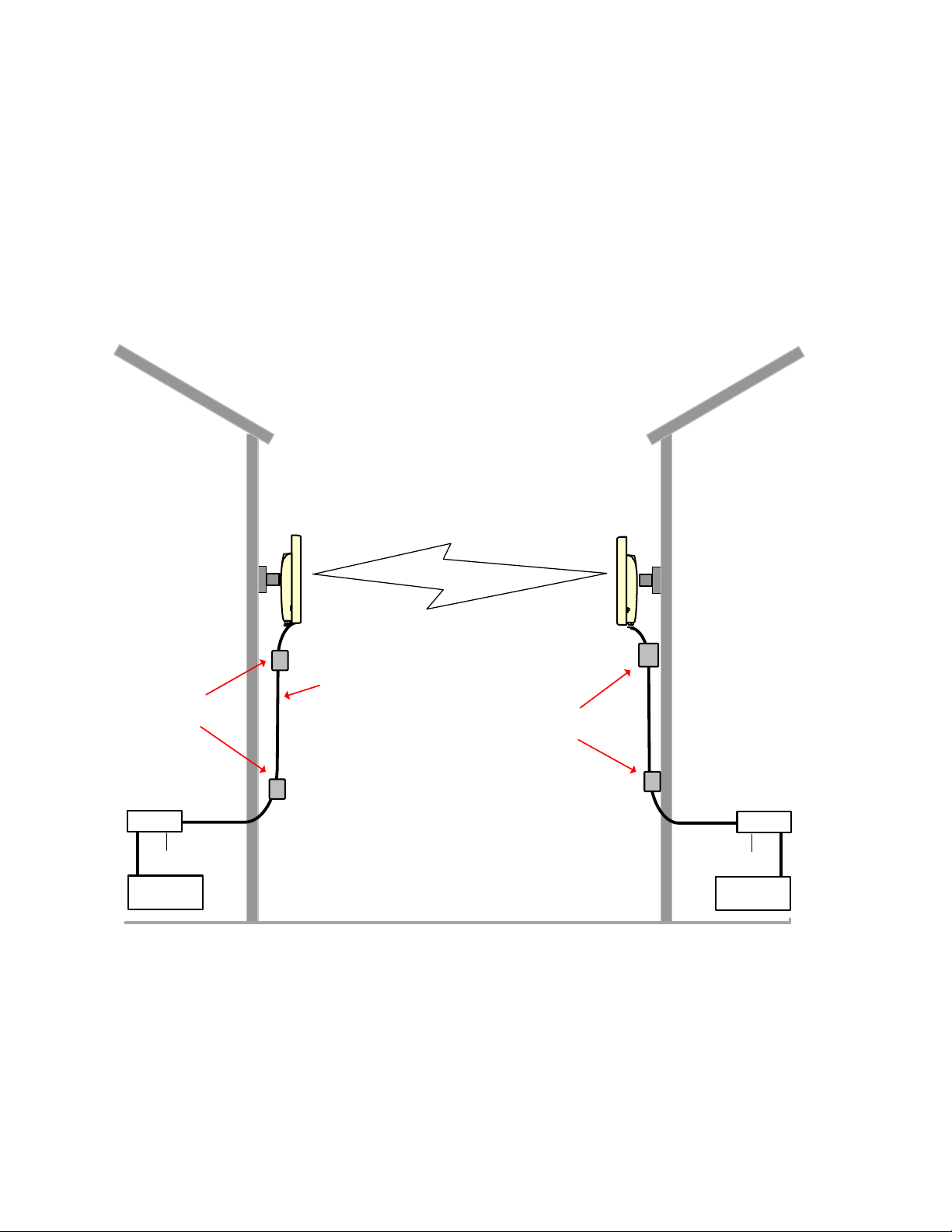
Chapter 1: Product description
Overview of the PMP/PTP 450(i) Series
Page 1-9
Typical deployment
The PMP/PTP 450(i) Series is an “all outdoor” solution consisting of a wireless bridge across sites.
Each site installation consists of an Integrated or Connectorized outdoor unit (ODU) and a power
supply (PSU) (see Figure 1). The ODU provides the following interfaces:
• Ethernet port: This provides proprietary power over Ethernet and connection to the
management and/or data networks.
Figure 1 PMP/PTP 450(i) Series typical bridge deployment
Building 1
ODU
AC supply
PSU
Network
equipment
Building 2
ODU
PSU
Network
equipment
AC supply
Power over Ethernet
interface
Lightning
protection units
Lightning
protection units
Page 46

Chapter 1: Product description
Overview of the PMP/PTP 450(i) Series
Page 1-10
Point-to- Multipoint
The PMP 450(i) Series consists of Access Point (AP) and Subscriber Module (SM) ODU. The radio
link operates on a single frequency channel in each direction using Time Division Duplex (TDD).
Applications for the PMP 450(i) Series include:
• High throughput enterprise applications
• nLOS video surveillance in metro areas
• Urban area network extension
• Network extension into areas with foliage
Point-to- Point (Backhaul)
The PTP 450(i) Series consists of two BH (Backhaul) ODUs. The customer can decide, via software
configuration, if this unit is a BHM (Backhaul Master) or a BHS (Backhaul Slave). The radio link
operates on a single frequency channel using Time Division Duplex (TDD).
Applications for the PTP 450(i) Series include:
• Enterprise Access
• nLOS video surveillance
• Leased line replacements and backup solutions
• Network extension
Product variants
The PMP 450(i) Series is available in the following product variants:
• The ODU is supplied in the following regional variants:
o FCC, intended for deployment in the USA
o EU, intended for deployment in countries of the European Union or other countries
following ETSI regulations
o Rest of the World (RoW), intended for deployment in countries other than USA and EU
countries.
o IC, intended for deployment in Canada
• An indoor power supply module providing Power-over-Ethernet (PoE) supply to ODU
(AP/SM/BH).
• Antennas and antenna cabling: Connectorized ODUs require external antennas connected
using RF cable.
• Ethernet cabling: All configurations require a copper Ethernet Cat5e connection from the ODU
(Ethernet port) to the PoE.
• Lightning protection unit (LPU): LPUs are installed in the ports copper drop cables to provide
transient voltage surge suppression.
• Ground cables: ODU, LPUs and outdoor copper Ethernet cables are bonded to the site
grounding system using ground cables.
Page 47

Chapter 1: Product description
Overview of the PMP/PTP 450(i) Series
Page 1-11
For more information about these components, including interfaces, specifications and Cambium
part numbers, refer to Chapter 2: System hardware.
Page 48
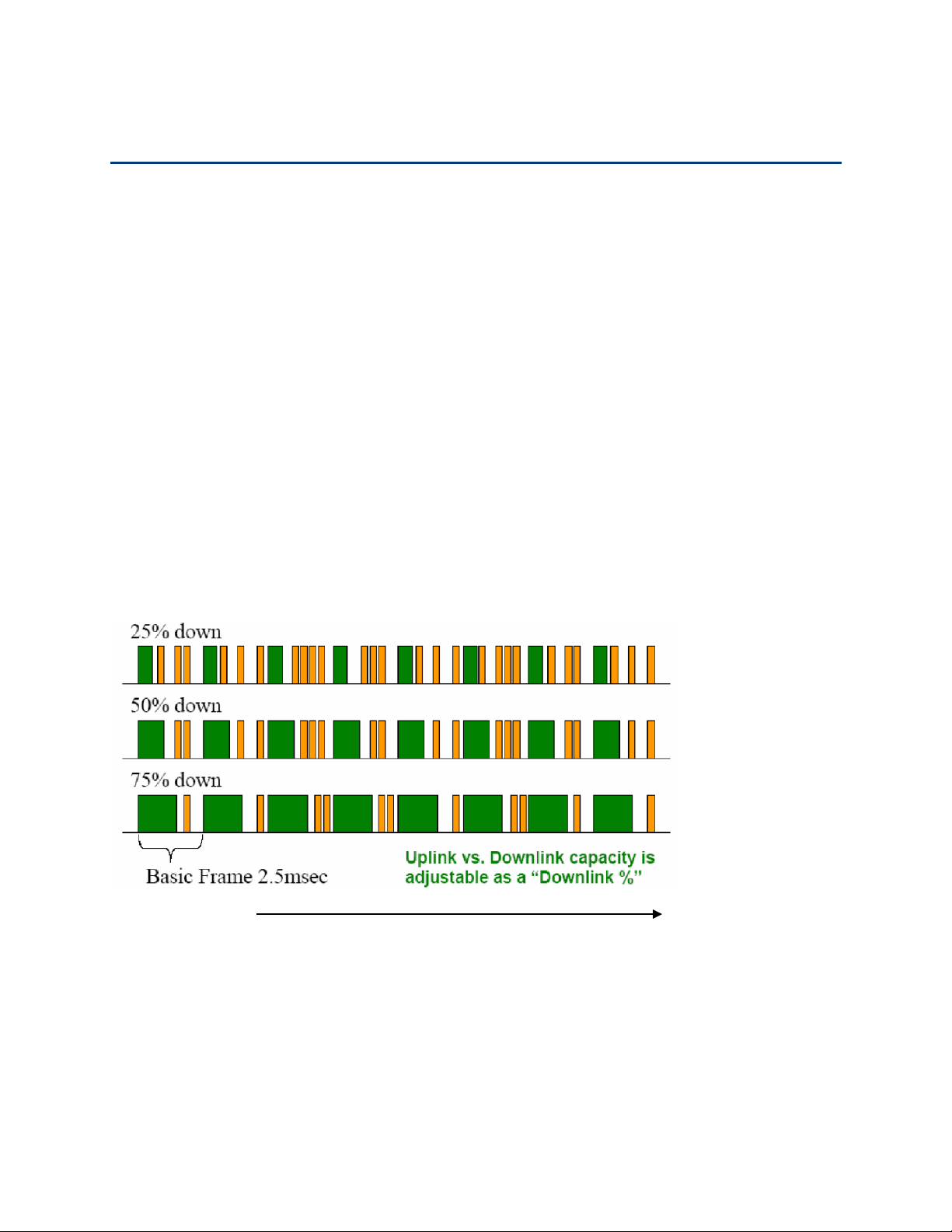
Chapter 1: Product description
Wireless operation
Page 1-12
Wireless operation
This section describes how the PMP/PTP 450(i) Series wireless link is operated, including
modulation modes, power control and security.
Time division duplexing
The system uses Time Division Duplexing (TDD) – one channel alternately transmits and receives
rather than using one channel for transmitting and a second channel for receiving. To accomplish
TDD, the AP/BHM must provide sync to its BHS. Furthermore, collocated APs/BHMs must be
synced together – an unsynchronized AP/BHM that transmits during the receive cycle of a
collocated AP/BHM can prevent a second AP/BHM from being able to decode the signals from its
APs/BHSs. In addition, across a geographical area, APs/BHMs that can “hear” each other benefit
from using a common sync to further reduce self-interference within the network.
Modules use TDD on a common frequency to divide frames for uplink (orange) and downlink
(green) usage, as shown in the figure below.
For more information on synchronization configuration options, see GPS synchronization on page
2-37.
Figure 2 TDD frame division
Time
Page 49

Chapter 1: Product description
Wireless operation
Page 1-13
TDD frame parameters
The TDD burst duration varies depending on the following:
• Channel Bandwidth
• Cyclic Prefix
• Frame Period
• Frame configuration - Downlink Data
• Link operation – Dynamic Rate Adaptation
OFDM and channel bandwidth
The PMP/PTP 450(i) series transmits using Orthogonal Frequency Division Multiplexing (OFDM).
This wideband signal consists of many equally spaced sub-carriers. Although each sub carrier is
modulated at a low rate using conventional modulation schemes, the resultant data rate from the
sub-carriers is high. OFDM works exceptionally over a Non-Line-of-Sight (NLoS) channel.
The channel bandwidth of the OFDM signal is configurable to one of the following values: 5, 10
and 20 MHz. Higher bandwidths provide greater link capacity at the expense of using more
bandwidth. Systems configured for a narrower channel bandwidth provide better receiver
sensitivity and can also be an appropriate choice in deployments where the amount of free
spectrum is limited.
Note
The Channel Bandwidth must be configured to the same value at both ends of the link.
Not all channel bandwidths are available in all regulatory bands.
Cyclic Prefix
OFDM technology uses a cyclic prefix, where a portion of the end of a symbol (slot) is repeated at
the beginning of the symbol (slot) to allow multi-pathing to settle before receiving the desired
data. A 1/16 cyclic prefix means that for every 16 bits of throughput data transmitted, an additional
bit is used.
Frame Period
The frame period or frame duration is the time between the beginning of a frame and the end of
the frame. The PMP/PTP 450(i) Series supports two frame periods: 2.5 ms and 5 ms.
The 5ms frame period configuration provides higher throughput as a result of reduced frame
overhead during transmission. In turn, the 2.5 ms frame period configuration affords reduced
latency in the system, half of that introduced by the 5 ms frame configuration.
Page 50

Chapter 1: Product description
Wireless operation
Page 1-14
Frame configuration - Downlink Data
The percentage of frame assigned to transport downlink data. The downlink data specifies the
percentage of the aggregate throughput for the downlink (frames transmitted from the AP/BHM to
the subscriber). The configurable range is 15 to 85 percent.
Link operation – Dynamic Rate Adapt
PMP/PTP 450(i) Series products offer eight levels or speeds of operation – 2X MIMO-B and 1X
MIMO-A (QPSK), 4X MIMO-B and 2X MIMO-A (16-QAM), 6x MIMO-B and 3X MIMO-A (64-QAM)
and 8X MIMO-B and 4X MIMO-A (265-QAM). If received power is less due to distance between the
AP/BHM and the SM/BHS or due to obstructions, or if interference affects the RF environment, the
system automatically and dynamically adjusts the links to the best operation level.
The system chooses its modulation rate dynamically, based on an internal ARQ (Automatic Repeat
reQuest) error control method. With ARQ, every data slot of every frame sent over the air (except
downlink broadcast) is expected to be acknowledged by the receiver, and if acknowledgement is
not received, the data is resent. The sending unit monitors these re-sends and adjusts the
modulation rate accordingly. It is normal to have links that change levels of operation as the RF
environment changes. Furthermore, the uplink or downlink portions of TDD duty cycle operate
independently; normal operation can have a downlink running at 6x while the uplink RF
environment only supports 2x.
The various modulation levels used by the PMP/PTP 450(i) are shown in Table 7.
Table 7 Modulation levels
Rate
MIMO-B
MIMO-A
QPSK
2X MIMO-B
1X MIMO-A
16-QAM
4X MIMO-B
2X MIMO-A
64-QAM
6X MIMO-B
3X MIMO-A
256-QAM
8X MIMO-B
4X MIMO-A
Note
MIMO-A achieves half the throughput of MIMO-B but adds a combining diversity (gain)
which enhances the link budget or availability.
Page 51

Chapter 1: Product description
Wireless operation
Page 1-15
MIMO
Multiple-Input Multiple-Output (MIMO) techniques provide protection against fading and increase
the probability that the receiver decodes a usable signal. When the effects of MIMO are combined
with those of OFDM techniques and a high link budget, there is a high probability of a robust
connection over a non-line-of-sight path.
The sub-features that comprises the MIMO techniques utilized in the PMP/PTP 450(i) product are:
• Matrix A: This technique enables the PMP/PTP 450(i) radio to use a scheme that optimizes
coverage by transmitting the same data over both antennas. This redundancy improves the
signal to noise ratio at the receiver making it more robust, at the cost of throughput.
• Matrix B: This technique provides for the ability to double the throughput of a radio
transmission under proper RF conditions. Different data streams are transmitted
simultaneously on two different antennas.
Encryption
The Cambium PMP/PTP 450(i) Series supports optional encryption for data transmitted over the
wireless link. The PTP 450(i) Series supports the following forms of encryption for security of the
wireless link:
• DES (Data Encryption Standard): An over-the-air link encryption option that uses secret
56-bit keys and 8 parity bits. DES performs a series of bit permutations, substitutions, and
recombination operations on blocks of data. DES encryption does not affect the performance
or throughput of the system.
• AES (Advanced Encryption Standard): An over-the-air link encryption option that uses
the Rijndael algorithm and 128-bit keys and 256-bit key size to establish a higher level of
security than DES. AES products are certified as compliant with the Federal Information
Processing Standards (FIPS 197) in the U.S.A.
Page 52

Chapter 1: Product description
System management
Page 1-16
System management
This section introduces the PMP/PTP 450(i) management system, including the web interface,
installation, configuration, alerts and upgrades.
Management agent
PMP/PTP 450(i) Series equipment is managed through an embedded management agent.
Management workstations, network management systems or PCs can be connected to this agent
using the module’s Ethernet port or over-the air (SM/BHS)
The management agent supports the following interfaces:
• Hypertext transfer protocol (HTTP)
• Hypertext transfer protocol secure (HTTPS)
• RADIUS authentication
• Simple network management protocol (SNMP) – v2c and v3
• Network time protocol (NTP)
• System logging (Syslog)
• Wireless Manager (WM) software
• Canopy Network Updater Tool (CNUT) software
Web server
The PMP/PTP 450(i) management agent contains a web server. The web server supports access via
the HTTP/HTTPS interface.
Web-based management offers a convenient way to manage the PMP/PTP 450(i) equipment from a
locally connected computer or from a network management workstation connected through a
management network, without requiring any special management software. The web and SNMP
are the interfaces supported for installation of PMP/PTP 450(i) and for the majority of PMP/PTP
450(i) configuration management tasks.
Page 53

Chapter 1: Product description
System management
Page 1-17
Web pages
The web-based management interfaces provide comprehensive web-based fault, configuration,
performance and security management functions organized into the following groups:
Access Point or Backhaul Master:
• Home
• Configuration
• Statistics
• Tools
• Logs
• Accounts
• Quick Start
• Copyright
Subscriber Module or Backhaul Slave
• Home
• Configuration
• Statistics
• Tools
• Logs
• Accounts
• PDA
• Copyright
Identity-based user accounts
• When identity-based user accounts are configured, a security officer can define from one to
four user accounts, each of which may have one of the four possible roles:
• ADMINISTRATOR, who has full read and write permissions. This is the level of the root and
admin users, as well as any other administrator accounts that one of them creates.
• INSTALLER, who has permissions identical to those of ADMINISTRATOR except that the
installer cannot add or delete users or change the password of any other user.
• TECHNICIAN, who has permissions to modify basic radio parameters and view informational
web pages
• GUEST, who has no write permissions and only a limited view of General Status tab
• Admin, Installer and Tech accounts can be configured as READ-ONLY. This will allow the
account to only see the items.
See Managing module access by passwords for detailed information on account permissions.
Page 54

Chapter 1: Product description
System management
Page 1-18
Remote Authentication Dial-in User Service (RADIUS)
The PMP 450(i) system includes support for RADIUS (Remote Authentication Dial In User Service)
protocol functionality including:
• Authentication: Allows only known SMs onto the network (blocking “rogue” SMs), and can be
configured to ensure SMs are connecting to a known network (preventing SMs from
connecting to “rogue” APs). RADIUS authentication is used for SMs, but not used for APs.
• SM Configuration: Configures authenticated SMs with MIR (Maximum Information Rate), High
Priority, and VLAN (Virtual LAN) parameters from the RADIUS server when a SM registers to
an AP.
• SM Accounting provides support for RADIUS accounting messages for usage-based billing.
This accounting includes indications for subscriber session establishment, subscriber session
disconnection, and bandwidth usage per session for each SM that connects to the AP.
• Centralized AP and SM user name and password management: Allows AP and SM usernames
and access levels (Administrator, Installer, Technician and Read-Only) to be centrally
administered in the RADIUS server instead of on each radio and tracks access events
(logon/logoff) for each username on the RADIUS server. This accounting does not track and
report specific configuration actions performed on radios or pull statistics such as bit counts
from the radios. Such functions require an Element Management System (EMS) such as
Cambium Wireless Manager. This accounting is not the ability to perform accounting functions
on the subscriber/end user/customer account.
• Framed-IP-Address: Operators may use a RADIUS server to assign management IP addressing
to SM modules.
SNMP
The management agent supports fault and performance management by means of an SNMP
interface. The management agent is compatible with SNMP v2c and SNMP v3 using Management
Information Base (MIB) files which are available for download from the Cambium Networks
Support website:
https://support.cambiumnetworks.com/files/ptp450
https://support.cambiumnetworks.com/files/pmp450
Network Time Protocol (NTP)
The clock supplies accurate date and time information to the system. It can be set to run with or
without a connection to a network time server (NTP). It can be configured to display local time by
setting the time zone and daylight saving in the Time web page.
If an NTP server connection is available, the clock can be set to synchronize with the server time at
regular intervals. PMP/PTP 450(i) devices may receive NTP data from a CMM4 module or an NTP
server configured in the system’s management network.
Page 55

Chapter 1: Product description
System management
Page 1-19
The Time Zone option is configurable on the AP’s/BHM’s Time Configuration page, and may be
used to offset the received NTP time to match the operator’s local time zone. When set on the
AP/BHM, the offset is set for the entire sector (AP/BHSs is notified of the current Time Zone upon
initial registration). If a Time Zone change is applied, the AP/BHSs are notified of the change in a
best effort fashion, meaning some AP/BHSs may not pick up the change until the next reregistration. Time Zone changes are noted in the Event Log.
An AP/BHM which is receiving NTP date and time information from an NTP server or from a GPS
synchronization source may be used as an NTP server. Any client which has IP connectivity to the
BHM may request NTP date and time information from the AP/BHM. No additional configuration
(other than the AP/BHM receiving valid NTP data) is required to use the AP/BHM as an NTP server.
Wireless Manager (WM)
Cambium Networks Wireless Manager 4.0 is recommended for managing PMP/PTP 450(i)
networks. You can achieve better uptime through better visibility of your network with the
Cambium Wireless Manager. This network management software tool offers breakthrough mapbased visualization capabilities using embedded Google maps, and combined with advanced
configuration, provisioning, alerting and reporting features you can control your entire outdoor
wireless network including Point-to-Multipoint and Point-to-Point solutions as well as other SNMP
enabled devices. With its powerful user interface you can not only be able to control your
network's access, distribution and backhaul layers, but can also have visibility to WLAN sites and
be able to quickly launch indoor network management systems. Some key features of Wireless
Manager are:
• Template-Based Configuration: With Wireless Manager's user-defined templates you can
accelerate the process for the configuration of the devices you add to your network resulting in
quicker and easier deployments. The template-based functionality provides an automated way
to configure large numbers of network devices with just a few mouse clicks, and can be
scheduled to occur at any time via Wireless Manager's Task Scheduler.
• Ultralight Thin Client: With the growing mobile workforce it is important to have access to
the status of your network at any time. With Wireless Manager you can view the status and
performance of your entire wireless network via a compact web interface accessible by your
smart phone.
• Map-Based Visualization: Wireless Manager overlays sophisticated real-time information
about your network elements onto building layouts and dynamic Google maps. Visuals can be
scaled to view an entire city or building or a specific area, floor or link.
• High Availability Architecture Support: Wireless Manager offers a high availability
option, providing a highly reliable and redundant network management solution that ensures
you always have management access to your network.
• High Scalability: The enhanced Wireless Manager offers you server scalability with support
for up to 10,000 nodes as well as support for distributed server architecture.
Cambium’s Wireless Manager 4.0 available for download at:
http://www.cambiumnetworks.com/support/management-tools/wireless-manager/
Page 56

Chapter 1: Product description
System management
Page 1-20
Canopy Network Updater Tool (CNUT)
CNUT (Canopy Network Updater Tool) is the stand-alone software update tool for PMP/PTP 450(i)
Series products. The CNUT 4.9.12 or greater should be used for 450(i) radios.
The Canopy Network Updater Tool has the following features:
• Automatically discovers all network elements
• HTTP and HTTPS
• Executes UDP command that initiates and terminates the Auto-update mode within APs/BHMs.
This command is both secure and convenient:
o For security, the AP/BHM accepts this command from only the IP address that specified in
the Configuration page of ODU.
o For convenience, Network Updater automatically sets this Configuration parameter in the
AP/BHM to the IP address of the Network Updater server when the server performs any of
the update commands.
• Allows you to choose among updating:
o Entire network.
o Only elements that you select.
o Only network branches that you select.
• Provides a Script Engine that you can use with any script which:
o The user can define.
o Cambium supplies.
CNUT is available at:
http://www.cambiumnetworks.com/support/management-tools/cnut/
Radio recovery mode – Radio Recovery Console /
Default Mode (fka Default Plug)
PMP/PTP 450i
The PMP/PTP 450i recovery mode provides a means to recover from serious configuration errors
including lost or forgotten passwords and unknown IP addresses.
Recovery mode also allows new main application software to be loaded even when the integrity of
the existing main application software image has been compromised. The most likely cause of an
integrity problem with the installed main application software is where the power supply has been
interrupted during a software upgrade.
The recovery mode supports a single IPv4 interface, with IP address 169.254.1.1, and with default
link settings.
Note
When Recovery has been entered through a power on/off/on cycle, the ODU will revert
to normal operation if no web access has been made to the unit within 30 seconds.
Page 57

Chapter 1: Product description
System management
Page 1-21
This prevents the unit remaining inadvertently in recovery following a power outage.
Recovery mode options
Options in recovery mode (IPv4 only) are as follows:
• Load a previous SW image
• Boot with default Canopy system software settings (similar to the hardware default plug on
previous Canopy-based PMP platforms)
The last most recent software image loaded to the board is retained. The factory image is not
retained.
Boot with default Canopy system software settings (similar to the hardware default plug on
previous Canopy-based PMP platforms).
See Error! Reference source not found. on page Error! Bookmark not defined..
PMP/PTP 450
A default plug (sometimes called an override plug) is available to provide access to a module
whose password and/or IP address have been forgotten. This plug allows the PMP 450 AP, PMP
450 SM, or PTP 450 BH to be accessed using IP address 169.254.1.1 and no password. During the
override session, you can assign any new IP address and set either or both user passwords
(display-only and/or full access) as well as make other parameter changes.
This plug is available from Best-Tronics Manufacturing, Inc.
See http://www.best-tronics.com/cambium.htm as Part BT-0583 (RJ-11 Default Plug). Alternatively,
you can fabricate an override plug. For pinout see Override plug cable on page 5-14.
Page 58

Page 2-1
Chapter 2: System hardware
This chapter describes the hardware components of a PMP/PTP 450(i) link.
The following topics are described in this chapter:
• System Components on page 2-2 describes system components of PTP and PMP including its
accessories.
• Cabling and lightning protection on page 2-26 describes various cable and lightning protection.
• Antennas and antenna cabling on page 2-34 describes supported antennas and its accessories.
• GPS synchronization on page 2-37 describes UGPS and CMM4.
Page 59

Chapter 2: System hardware
System Components
Page 2-2
System Components
Point-to-Multipoint (PMP)
The PMP radio is a transceiver device. It is a connectorized or radiated outdoor unit containing all
the radio, networking, and surge suppression electronics. It can be purchased as:
• Access Point Module (AP)
• Subscriber Module (SM)
PMP 450(i) - Integrated or Connectorized ODU
The PMP 450i and PMP 450 ODUs are supplied in Integrated or Connectorized configurations.
See Table 2 PMP/PTP 450i Series hardware configurations on page 1-4
See Table 4 PMP/PTP 450 Series hardware configurations on page 1-7
Page 60

Chapter 2: System hardware
System Components
Page 2-3
Product variants
Table 8 PMP 450i variants
Variant
Region
Antenna
Frequency
Range
Channel
Bandwidt
h
Max
Tx
Power
Notes
900
MHz13
PMP 450i
AP
FCC
Connectorized
902 - 928
MHz
5, 7, 10, 20
MHz
25 dBm
Transmit power
limited based
on regional
setting
5 GHz
PMP 450i
AP
FCC
Connectorized
4900 – 5925
MHz
5, 10, 20
MHz
27 dBm
Transmit power
limited based
on regional
setting
Integrated 16 dBi
90 degree
RoW
Connectorized
Integrated 23 dBi
Canada
Connectorized
Integrated 23 dBi
RoW DES
Connectorized
Integrated 23 dBi
5 GHz
PMP 450i
SM
FCC
Connectorized
4900 – 5925
MHz
5, 10, 20
MHz
27 dBm
Transmit power
limited based
on regional
setting
Integrated 23 dBi
RoW
Connectorized
Integrated 23 dBi
Canada
Connectorized
Integrated 23 dBi
RoW DES
Connectorized
Integrated 23 dBi
13
900 MHz support planned for future release.
Page 61

Chapter 2: System hardware
System Components
Page 2-4
Table 9 PMP 450 variants
Variant
Region
Antenna
Frequency
Range
Channel
Bandwidt
h
Max
Tx
Power
Notes
2.4 GHz
PMP 450
AP
FCC ISM
Connectorized
2400 –
2483.5 MHz
5, 10, 20
MHz
27 dBm
Transmit power
limited based
on regional
setting
Integrated 18 dBi
3.5 GHz
PMP 450
AP
FCC ISM
Connectorized
3300 – 3600
MHz
5, 7, 10, 20
MHz
27 dBm
Transmit power
limited based
on regional
setting
Integrated 16 dBi
3.65 GHz
PMP 450
AP
FCC ISM
Connectorized
3550 – 3800
MHz
5, 7, 10, 20
MHz
27 dBm
Transmit power
limited based
on regional
setting
Integrated 16 dBi
5.4/5.8
GHz
PMP 450
AP
FCC
Connectorized
5470 – 5875
MHz
10, 20 MHz
(5 MHz not
available
in DFS
regions(
27 dBm
Transmit power
limited based
on regional
setting
Integrated 17 dBi
RoW
Connectorized
Integrated 17 dBi
Canada
Connectorized
Integrated 17 dBi
RoW DES
Connectorized
Integrated 23 dBi
900 MHz
PMP 450i
SM14
FCC
Connectorized
902 - 928
MHz
5, 7, 10, 20
MHz
25 dBm
Transmit power
limited based
on regional
setting
Note
Not all variants may be available at the same time in some or all regions. Please
contact your sales representative for details on availability.
14
900 MHz support planned for future release.
Page 62

Chapter 2: System hardware
System Components
Page 2-5
Backhaul (PTP)
The Backhaul radio is a transceiver device. It is a connectorized or integrated outdoor unit
containing all the radio, networking, and surge suppression electronics. It can be configured as:
• Backhaul Master (BHM)
• Backhaul Slave (BHS)
PTP 450(i) - Integrated or Connectorized ODU
See Table 2 PMP/PTP 450i Series hardware configurations on page 1-4
See Table 4 PMP/PTP 450 Series hardware configurations on page 1-7
Product variants
Table 10 PTP 450i variants
Variant
Region
Antenna
Frequency
Range
Channe
l
Bandwi
dth
Max
Tx
Power
Notes
5 GHz
PTP 450i
FCC
Connectorized
4900 – 5925
MHz
5, 10, 20
MHz
27 dBm
Transmit power
limited based
on regional
setting
Integrated 23 dBi
RoW
Connectorized
Integrated 23 dBi
Canada
Connectorized
Integrated 23 dBi
RoW
DES
Connectorized
Integrated 23 dBi
Page 63

Chapter 2: System hardware
System Components
Page 2-6
Table 11 PTP 450 variants
Variant
Region
Antenna
Frequency
Range
Channe
l
Bandwi
dth
Max
Tx
Power
Notes
3.5 GHz
PTP 450
BH
ROW
Connectorized
3300 – 3600
MHz
5, 7, 10,
20 MHz
27 dBm
Transmit power
limited based
on regional
setting
Integrated 16 dBi
3.65 GHz
PTP 450
BH
ROW
Connectorized
3550 – 3800
MHz
5, 7, 10,
20 MHz
27 dBm
Transmit power
limited based
on regional
setting
Integrated 16 dBi
5.4/5.8
GHZ PTP
450 BH
FCC
Connectorized
5470 – 5875
MHz
5, 7, 10,
20 MHz
27 dBm
Transmit power
limited based
on regional
setting
Integrated 17 dBi
5 GHz
PTP 450
BH
FCC
Connectorized
4900 – 5925
MHz
5, 10, 20
MHz
27 dBm
Transmit power
limited based
on regional
setting
Integrated 23 dBi
RoW
Connectorized
Integrated 23 dBi
Canada
Connectorized
Integrated 23 dBi
RoW
DES
Connectorized
Integrated 23 dBi
Note
Not all variants may be available at the same time in some or all regions. Please
contact your sales representative for details on availability.
Page 64
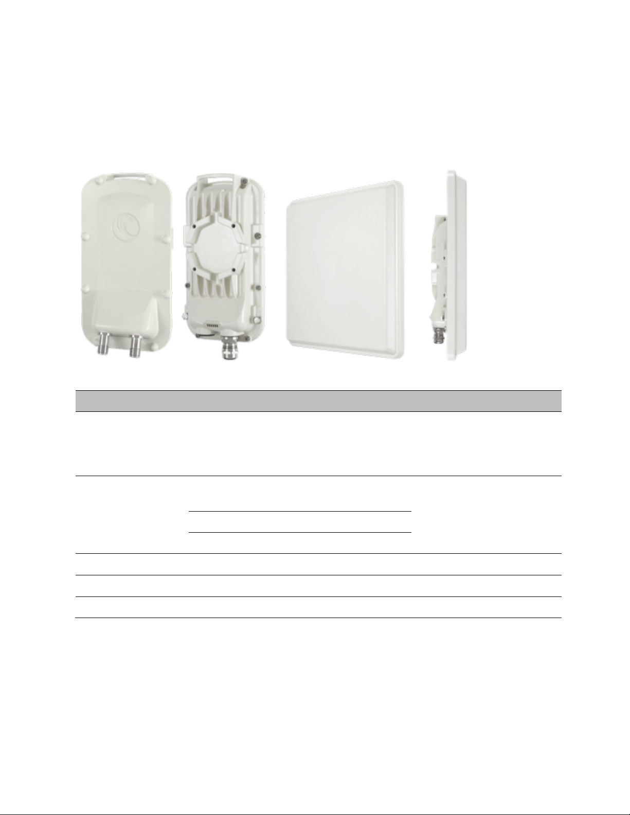
Chapter 2: System hardware
System Components
Page 2-7
PMP/PTP 450(i) interfaces
PMP/PTP 450i interfaces – AP/SM/BH
The AP/SM/BH interfaces are illustrated below.
Figure 5 PMP/PTP 450i interfaces
Table 12 AP/SM/BH interface descriptions and cabling
Interface
Function
Cabling
PSU/Ethernet
Power-over-Ethernet, Ethernet
communications (management and data),
CMM sync-over-power synchronization
input
RJ45 Cable
See Table 63 on page 5-11
Aux/Sync
GPS synchronization input and output,
UGPS power output
RJ 45 Cable
See Table 64 on page 5-11
Audio tones
Data
RF Port A
Vertical RF connection to antenna
50 ohm RF cable, N-type
RF Port B
Horizontal RF connection to antenna
50 ohm RF cable, N-type
Ground Lugs
For grounding the unit
10 AWG copper wire
Page 65
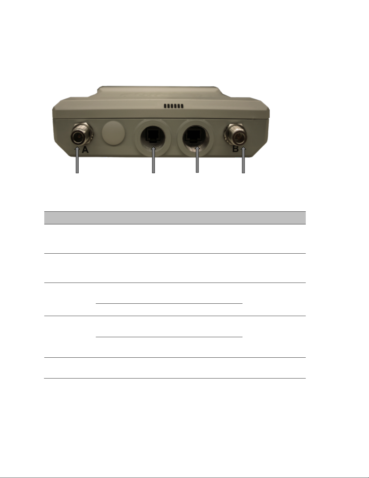
Chapter 2: System hardware
System Components
Page 2-8
PMP/PTP 450 interfaces - AP
The PMP 450 AP interfaces are illustrated below.
Figure 5 PMP/PTP 450 interfaces - AP
Table 13 AP interface descriptions and cabling – 2.4 GHz, 5 GHz
Interface
Function
Cabling
PSU/Ethernet
Power-over-Ethernet, Ethernet
communications (management and
data)
RJ45 Cable
Sync/Default
GPS synchronization signaling,
provides power to UGPS module.
Default plug port.
RJ11 cable, default
plug.
RF Port A
2.4 GHz
-45 degree RF connection to AP
antenna
50 ohm RF cable,
N-type
5 GHz
Vertical RF connection to AP antenna
RF Port B
2.4 GHz
+45 degree RF connection to AP
antenna
50 ohm RF cable,
N-type
5 GHz
Horizontal RF connection to AP
antenna
Ground Lugs
For grounding the unit
10 AWG copper
wire
Path A RF Port
Sync/Default
Ethernet
Path B RF port
Page 66
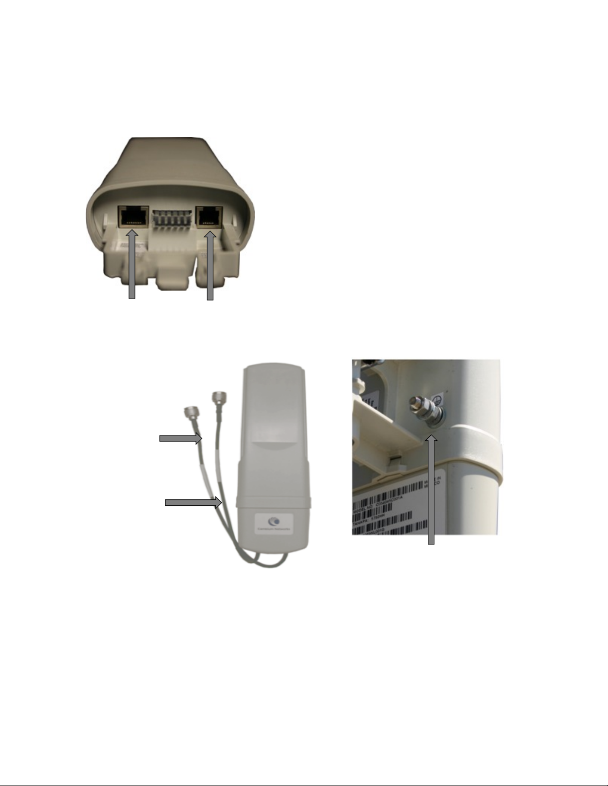
Chapter 2: System hardware
System Components
Page 2-9
PMP/PTP 450 interfaces – SM/BH
The PMP 450 SM/BH interfaces are illustrated below.
Figure 5 PMP/PTP 450 interfaces – SM/BH
Figure 5 PMP/PTP 450 interfaces – SM/BH Connectorized
Ethernet Sync/Defaul
Page 67
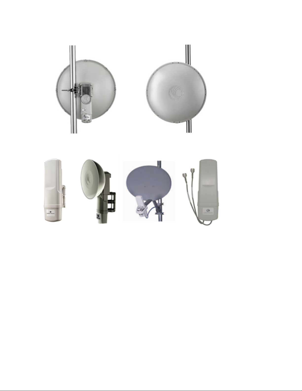
Chapter 2: System hardware
System Components
Page 2-10
Figure 5 PMP 450d SM - Integrated Dish
Figure 5 PTP 450 Series – BHM/BHS
Page 68
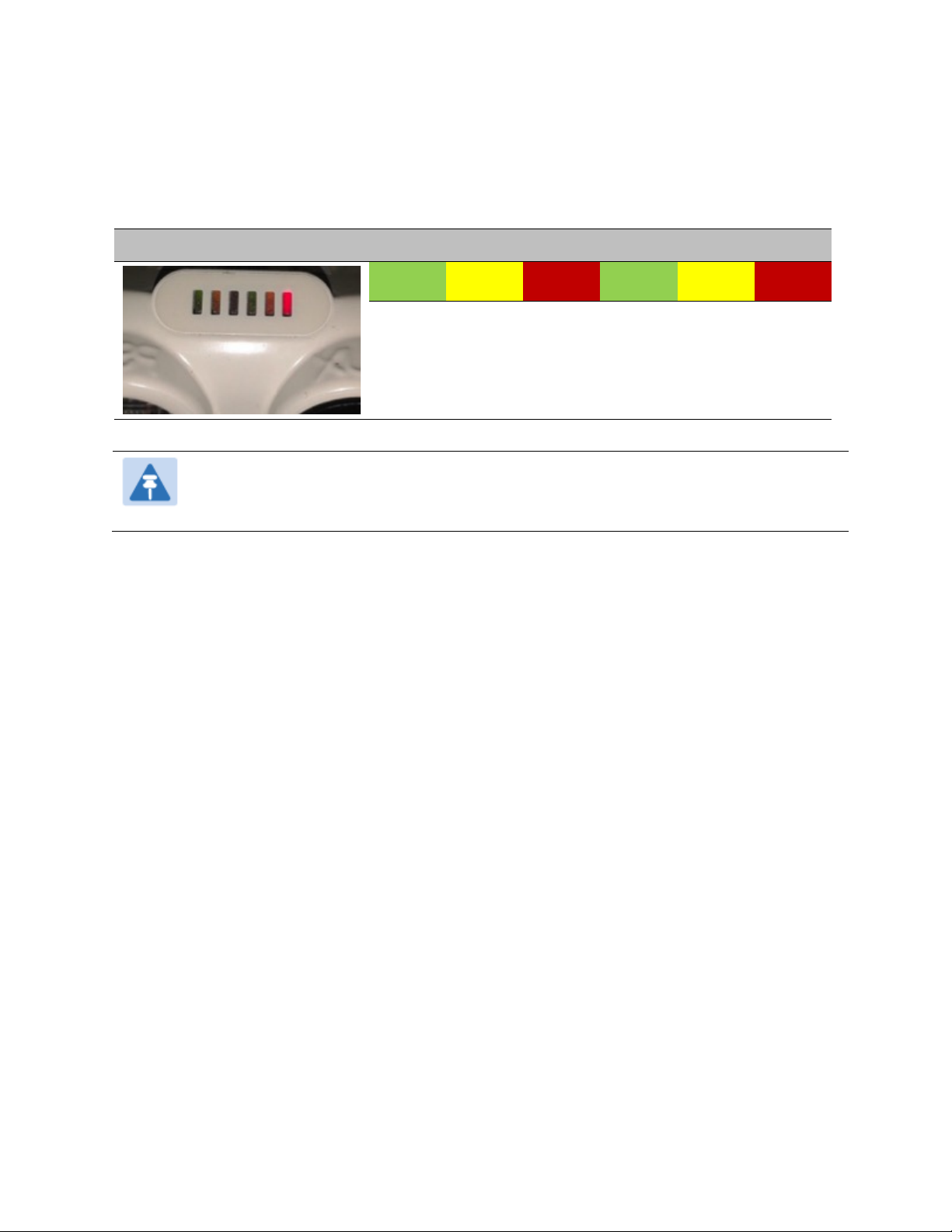
Chapter 2: System hardware
System Components
Page 2-11
Diagnostic LEDs
The diagnostic LEDs of PMP 450(i) Series are as shown in Figure 3.
Figure 3 Radio diagnostic LEDs, viewed from unit front
ODU LED Display
LED Labels
LNK/5
ACT/4
GPS/3
SES/2
SYN/1
PWR
Note
The LED color helps distinguish the position of LED. The LED color does not indicate
any status.
AP/BHM LEDs
The diagnostic LEDs report the information about the status of the BHM/AP.
Page 69

Chapter 2: System hardware
System Components
Page 2-12
Table 14 AP/BHM LED descriptions
LED
Color when
active
Status
information
provided
Notes
PWR
Red
DC power
Always lit after 10-20 seconds of power
on.
SYN/1
Yellow
Presence of sync
-
SES/2
Green
Unused
-
GPS/3
Red
Pulse of sync
Lit when the AP/BHM is getting a sync
pulse from a GPS source goes along
with SYN/1
ACT/4
Yellow
Presence of data
activity on the
Ethernet link
Flashes during data transfer. Frequency
of flash is not a diagnostic indication.
LNK/5
For PMP/PTP
450i
Red/ Green/Orange
(bi-colored for
10/100/1000)
Ethernet link
Ethernet link
Continuously lit when link is present.
10Base-T : Red
100Base-T : Green
1000Base-T : Orange
For PMP/PTP
450
Green
Continuously lit when link is present.
Note
The LED color helps you distinguish position of the LED. The LED color does not
indicate any status.
SM/BHS LEDs
The SM/BHS LEDs provide different status of radio based on the operating modes. A SM/BHS in
“operating” mode registers and passes traffic normally. A SM/BHS in “aiming” mode does not
register or pass the traffic, but displays (via LED panel) the strength of received radio signals
(based on radio channel selected via Tools -> Alignment).
Page 70

Chapter 2: System hardware
System Components
Page 2-13
Table 15 SM/BHS LED descriptions
Status information provided
LED
Color when
active
SM / BHS in
“Operating”
Mode
SM / BHS in
“Aiming” Mode
Notes
PWR
Red
DC power
Always lit after 10-20
seconds of power on.
SYN/1
Yellow
Presence of sync
These five LEDs
act as a bar graph
to indicate the
relative quality of
alignment. As
power level
improves during
alignment, more
of these LEDs are
lit.
Lit when SM/BHS is in sync
with an AP/BHM.
SES/2
Green
Session Indicator
Lit when SM/BHS is in
session.
GPS/3
Red
Unused
On - high interference.
Blinking - medium
interference.
Off - low interference.
ACT/4
Yellow
Presence of data
activity
on the Ethernet link
Flashes during data transfer.
Frequency of flash is not a
diagnostic indication.
LNK/5
For
PMP/PTP
450i
Red/ Green/
Orange
(bi-colored for
10/100/1000)
Ethernet link
Continuously lit when link is
present.
10Base-T : Red
100Base-T : Green
1000Base-T : Orange
For
PMP/PTP
450
Green
Ethernet link
Continuously lit when link is
present.
Operating Mode
• Scanning: If the SM/BHS is not registered to AP/BHM, then these three LEDs cycle on and off
from left to right (SYN/1, SES/2 and GPS/3).
• Ethernet Link: The LNK/5 LED lit continuously when link is present.
• Data Transfer: The ACT/4 LED lit on the presence of data activity on the Ethernet link.
Page 71

Chapter 2: System hardware
System Components
Page 2-14
Aiming Mode
The 5 LEDs (SYN/1, SES/2, GPS/3, ACT/4 and LNK/5) are turned into a 5-position bar graph. The
more LEDs that are lit, the better the received power the module is seeing. The colors of the LEDS
have no particular meaning other than to assist is distinguishing one position from the next.
ODU part numbers
Order PMP/PTP 450i and PMP/PTP 450 Series products from Cambium Networks.
PMP 450i
Table 16 PMP 450i ODU part numbers
Cambium description
Cambium part
number
PMP 450i AP (Access Point)
5 GHz PMP 450i Connectorized Access Point (RoW)
C050045A001A
5 GHz PMP 450i Connectorized Access Point (FCC)
C050045A002A
5 GHz PMP 450i Connectorized Access Point (EU)
C050045A003A
5 GHz PMP 450i Connectorized Access Point (DES Only)
C050045A004A
5 GHz PMP 450i Connectorized Access Point (IC)
C050045A015A
5 GHz PMP 450i AP, Integrated 90°sector antenna (RoW)
C050045A005A
5 GHz PMP 450i AP, Integrated 90°sector antenna (FCC)
C050045A006A
5 GHz PMP 450i Integrated Access Point, 90 degree (EU)
C050045A007A
5 GHz PMP 450i AP, Integrated 90°sector antenna (DES only)
C050045A008A
5 GHz PMP 450i AP, Integrated 90°sector antenna (IC)
C050045A016A
900 MHz15 PMP 450i Connectorized Access Point
C009045A001A
PMP 450i SM (Subscriber Module)
5 GHz PMP 450i Connectorized Subscriber Module
C050045C001A
5 GHz PMP 450i SM, Integrated High Gain Antenna
C050045C002A
900 MHz PMP 450i Connectorized Subscriber Module
C009045C001A
15
900 MHz support planned for future release.
Page 72

Chapter 2: System hardware
System Components
Page 2-15
PTP 450i
Table 17 PTP 450i ODU part numbers
Cambium description
Cambium part
number
5 GHz PTP 450i END, Connectorized (RoW)
C050045B001A
5 GHz PTP 450i END, Integrated High Gain Antenna (RoW)
C050045B002A
5 GHz PTP 450i END, Connectorized (FCC)
C050045B003A
5 GHz PTP 450i END, Connectorized (EU)
C050045B005A
5 GHz PTP 450i END, Connectorized (DES only)
C050045B007A
5 GHz PTP 450i END, Connectorized (IC)
C050045B015A
5 GHz PTP 450i END, Integrated High Gain Antenna (FCC)
C050045B004A
5 GHz PTP 450i END, Integrated High Gain Antenna (EU)
C050045B006A
5 GHz PTP 450i END, Integrated High Gain Antenna (DES only)
C050045B008A
5 GHz PTP 450i END, Integrated High Gain Antenna (IC)
C050045B016A
Ethernet cable adapter for CMM4
N000045L001A
PMP 450
Table 18 PMP 450 ODU part numbers
Cambium description
Cambium part
number
PMP 450 AP (Access Point)
2.4 GHz PMP 450 Connectorized Access Point
C024045A001A
2.4 GHz PMP 450 Connectorized Access Point (DES)
C024045A003A
3.5 GHz PMP 450 Connectorized Access Point
C035045A001A
3.5 GHz PMP 450 Connectorized Access Point (DES)
C035045A003A
3.6 GHz PMP 450 Connectorized Access Point
C036045A001A
3.6 GHz PMP 450 Connectorized Access Point (DES)
C036045A003A
5 GHz PMP 450 Connectorized Access Point
C054045A001A
5 GHz PMP 450 Connectorized Access Point (US only)
C054045A002A
5 GHz PMP 450 Connectorized Access Point (DES)
C054045A003A
PMP 450 AP Lite
Page 73

Chapter 2: System hardware
System Components
Page 2-16
Cambium description
Cambium part
number
2.4 GHz PMP 450 Connectorized Access Point - Lite
C024045A011A
3.3-3.6 GHz PMP 450 Connectorized Access Point - Lite
C035045A011A
3.55-3.8 GHz PMP 450 Connectorized Access Point - Lite
C036045A011A
5 GHz PMP 450 Connectorized Access Point - Lite
C054045A011A
5 GHz PMP 450 Connectorized Access Point (FCC) - Lite
C054045A012A
PMP 450 SM (Subscriber Module)
2.4 GHz PMP 450 Subscriber Module, 4 Mbps
C024045C001A
2.4 GHz PMP 450 Subscriber Module, 10 Mbps
C024045C002A
2.4 GHz PMP 450 Subscriber Module, 20 Mbps
C024045C003A
2.4 GHz PMP 450 Subscriber Module, Uncapped
C024045C004A
2.4 GHz PMP 450 Connectorized Subscriber Module, 4 Mbps
C024045C005A
2.4 GHz PMP 450 Connectorized Subscriber Module, 10 Mbps
C024045C006A
2.4 GHz PMP 450 Connectorized Subscriber Module, 20 Mbps
C024045C007A
2.4 GHz PMP 450 Connectorized Subscriber Module, Uncapped
C024045C008A
3.5 GHz PMP 450 Subscriber Module, 4 Mbps
C035045C001A
3.5 GHz PMP 450 Subscriber Module, 10 Mbps
C035045C002A
3.5 GHz PMP 450 Subscriber Module, 20 Mbps
C035045C003A
3.5 GHz PMP 450 Subscriber Module, Uncapped
C035045C004A
3.5 GHz PMP 450 Connectorized Subscriber Module, 4 Mbps
C035045C005A
3.5 GHz PMP 450 Connectorized Subscriber Module, 10 Mbps
C035045C006A
3.5 GHz PMP 450 Connectorized Subscriber Module, 20 Mbps
C035045C007A
3.5 GHz PMP 450 Connectorized Subscriber Module, Uncapped
C035045C008A
3.6 GHz PMP 450 Subscriber Module, 4 Mbps
C036045C001A
3.6 GHz PMP 450 Subscriber Module, 10 Mbps
C036045C002A
3.6 GHz PMP 450 Subscriber Module, 20 Mbps
C036045C003A
3.6 GHz PMP 450 Subscriber Module, Uncapped
C036045C004A
3.6 GHz PMP 450 Connectorized Subscriber Module, 4 Mbps
C036045C005A
3.6 GHz PMP 450 Connectorized Subscriber Module, 10 Mbps
C036045C006A
3.6 GHz PMP 450 Connectorized Subscriber Module, 20 Mbps
C036045C007A
Page 74

Chapter 2: System hardware
System Components
Page 2-17
Cambium description
Cambium part
number
3.6 GHz PMP 450 Connectorized Subscriber Module, Uncapped
C036045C008A
5 GHz PMP 450 Connectorized Subscriber Module, 4 Mbps
C054045C005A
5 GHz PMP 450 Connectorized Subscriber Module, 10 Mbps
C054045C006A
5 GHz PMP 450 Connectorized Subscriber Module, 20 Mbps
C054045C007A
5 GHz PMP 450 Connectorized Subscriber Module, Uncapped
C054045C008A
5 GHz PMP 450 Integrated Subscriber Module, 4 Mbps
C054045C001B
5 GHz PMP 450 Integrated Subscriber Module, 10 Mbps
C054045C002B
5 GHz PMP 450 Integrated Subscriber Module, 20 Mbps
C054045C003B
5 GHz PMP 450 Integrated Subscriber Module, Uncapped
C054045C004B
5 GHz PMP 450 Connectorized Subscriber Module, 4 Mbps
C054045C005B
6 GHz PMP 450 Connectorized Subscriber Module, 10 Mbps
C054045C006B
7 GHz PMP 450 Connectorized Subscriber Module, 20 Mbps
C054045C007B
8 GHz PMP 450 Connectorized Subscriber Module, Uncapped
C054045C008B
5 GHz PMP 450d Subscriber Module, 20 Mbps – PMP 450d Radio
Only
C054045C013B
5 GHz PMP 450d Subscriber Module, Uncapped – PMP 450d Radio
Only
C054045C014B
5 GHz PMP 450d Subscriber Module, 20 Mbps – PMP 450d
C054045H013B
5 GHz PMP 450d Subscriber Module, Uncapped – PMP 450d
C054045H014B
PTP 450
Table 19 PTP 450 ODU part numbers
Cambium description
Cambium part
number
3.5 GHz PTP 450 BH Unit
C035045A001A
3.5 GHz PTP 450 BH Unit, DES only
C035045A003A
PTP 450 3.5 GHz END – Integrated
C035045B001A
PTP 450 3.5 GHz END – Connectorized
C035045B002A
PTP 450 3.5 GHz END – Integrated – DES Only
C035045B003A
PTP 450 3.5 GHz END – Connectorized – DES Only
C035045B004A
Page 75

Chapter 2: System hardware
System Components
Page 2-18
Cambium description
Cambium part
number
3.6 GHz PTP 450 BH Unit
C036045A001A
3.6 GHz PTP 450 BH Unit, DES only
C036045A003A
PTP 450 3.65 GHz END – Integrated
C036045B001A
PTP 450 3.65 GHz END – Connectorized
C036045B002A
PTP 450 3.65 GHz END – Integrated – DES Only
C036045B003A
PTP 450 3.65 GHz END – Connectorized – DES Only
C036045B004A
5 GHz PTP 450 BH Unit
C054045A001A
5 GHz PTP 450 BH Unit, US only
C054045A002A
5 GHz PTP 450 BH Unit, DES only
C054045A003A
PTP 450 5 GHz END – Integrated (ROW)
C054045B001A
PTP 450 5 GHz END – Connectorized (ROW)
C054045B002A
PTP 450 5 GHz END – Integrated (ROW) – DES Only
C054045B003A
PTP 450 5 GHz END – Connectorized (ROW) – DES Only
C054045B004A
PTP 450 5 GHz END – Integrated (FCC)
C054045B005A
PTP 450 5 GHz END – Connectorized (FCC)
C054045B006A
PMP/PTP 450 Accessories
Cambium description
Cambium part
number
PMP 450 AP Antenna Options
5 GHz Antenna for 90 Degree Sector
85009324001
5 GHz Antenna for 60 Degree Sector
85009325001
2.4 GHz Dual Slant Antenna for 60 Degree Sector
C024045D601A
3.5 GHz and 3.6 GHz Dual Slant Antenna for 90 Degree Sector
C030045D901A
N-type to N-type cable (16 inch length)
30009406002
AP Optional Equipment
Gigabit Enet Capable Power Supply - 30VDC, 15W
N000900L001A
Cable, UL Power Supply Cord Set, US
N000900L007A
Cable, UL Power Supply Cord Set, EU
N000900L008A
Page 76

Chapter 2: System hardware
System Components
Page 2-19
Cambium description
Cambium part
number
Cable, UL Power Supply Cord Set, UK
N000900L009A
Power Supply,120W 30VDC AT 60C 100-240VAC EL5
ACPS120WA
Surge Protector
600SSH
Universal Mounting Bracket
SMMB2A
CMM MICRO (Outdoor Enclosure)
1070CKHH
CMM4 W/RUGGEDIZED Switch and GPS
1090CKHH
CMM4 NO Switch
1091HH
CMM4 Rack Mount Assembly
1092HH
Universal GPS Module
1096H
SM Optional Equipment
Gigabit Enet Capable Power Supply - 30VDC, 15W
N000900L001A
Cable, UL Power Supply Cord Set, US
N000900L007A
Cable, UL Power Supply Cord Set, EU
N000900L008A
Cable, UL Power Supply Cord Set, UK
N000900L009A
53CM Offset, Reflector Dish Kit, 4PK
HK2022A
Universal Mounting Kit
SMMB1A
Surge Protector
600SSH
Upgrade Keys
PMP 450 4 To 10 Mbps Upgrade Key
C000045K002A
PMP 450 4 To 20 Mbps Upgrade Key
C000045K003A
PMP 450 4 To Uncapped Upgrade Key
C000045K004A
PMP 450 10 To 20 Mbps Upgrade Key
C000045K005A
PMP 450 10 To Uncapped MBPS Upgrade Key
C000045K006A
PMP 450 20 To Uncapped MBPS Upgrade Key
C000045K007A
PMP 450 Lite AP to Full AP Upgrade Key
C000045K008A
Extended Warranty
PMP450 AP Extended Warranty, 1 Additional Year
SG00TS4009A
PMP450 AP Extended Warranty, 2 Additional Years
SG00TS4017A
PMP450 AP Extended Warranty, 4 Additional Years
SG00TS4025A
Page 77

Chapter 2: System hardware
System Components
Page 2-20
Cambium description
Cambium part
number
PMP450 SM Extended Warranty, 1 Additional Year
SG00TS4010A
PMP450 SM Extended Warranty, 2 Additional Years
SG00TS4018A
PMP450 SM Extended Warranty, 4 Additional Years
SG00TS4026A
Power supply options
The PMP/PTP 450(i) is powered over its Main Ethernet cable using Power Over Ethernet (POE). The
power injector is connected to the ODU and network terminating equipment using Cat5e cable
with RJ45 connectors.
Power supply – PMP/PTP 450i
The PMP/PTP 450i support powering from the following powering sources:
• Power Suppy, 60 W, 56 V with Gbps support
• AC+DC Enhanced Power Injector
• Power over Ethernet midspan, 60 W, -48 VDC Input
• CMM4 with external 56 V power supply
• IEEE802.3at power injector
Please refer to Ethernet standards and cable lengths on Page 2-27 for details on maximum cable
lengths between power injector and PMP/PTP 450i.
PSU part numbers
Table 20 PSU part numbers for PMP/PTP 450i
Cambium description
Cambium part
number
Power supply, 60 W, 56 V with Gbps support
N000065L001B
AC+DC Enhanced Power Injector
C000065L002A
Power over Ethernet midspan, 60 W, -48 VDC Input
N000000L036A
AC Power Injector
The AC Power Injector interfaces are shown in Figure 4 and described in Table 21.
Page 78
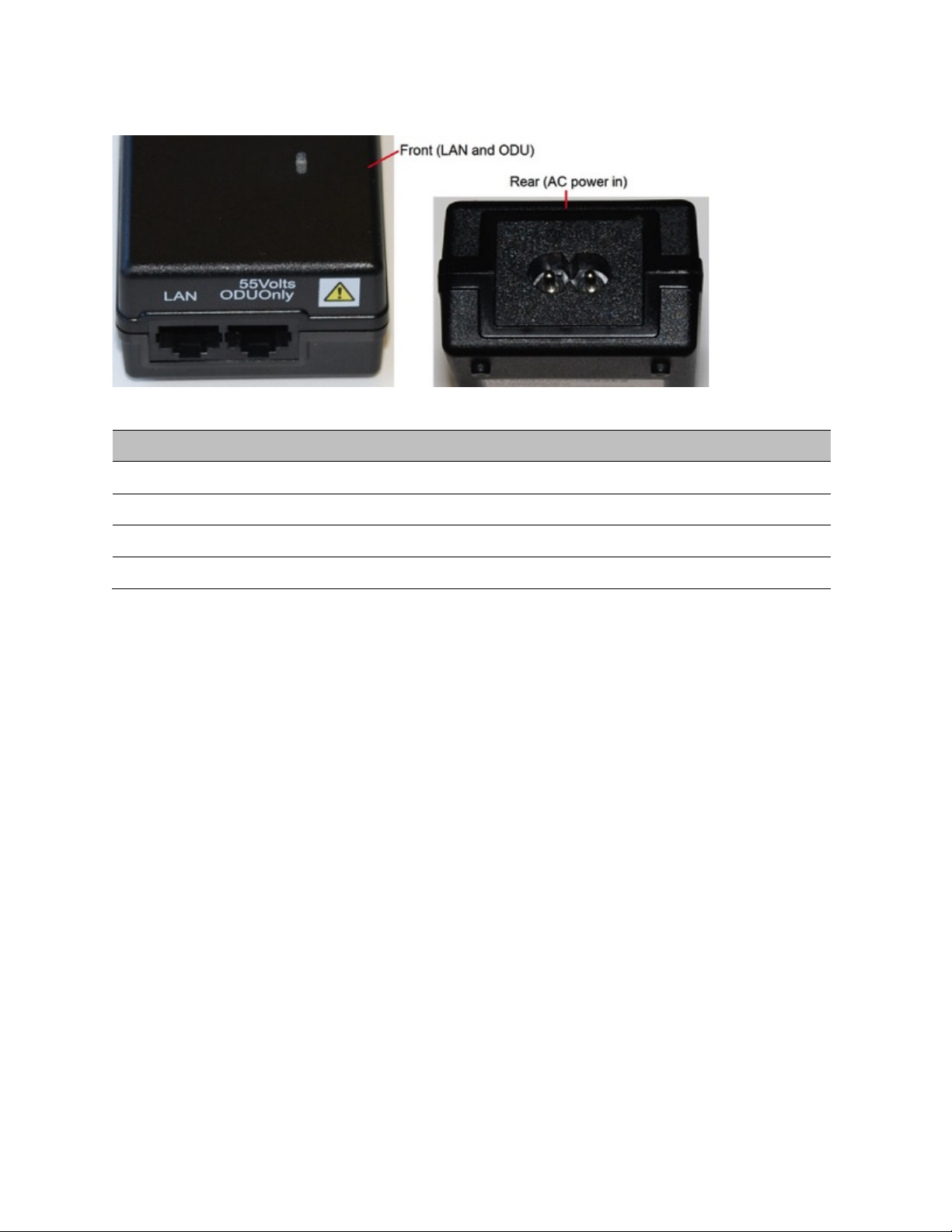
Chapter 2: System hardware
System Components
Page 2-21
Figure 4 AC Power Injector interfaces
Table 21 AC Power Injector interface functions
Interface
Function
AC power in
AC power input (main supply)
ODU
RJ45 socket for connecting Cat5e cable to ODU
LAN
RJ45 socket for connecting Cat5e cable to network
Power (green) LED
Power supply detection
AC+DC Enhanced Power Injector
The AC+DC Enhanced Power Injector interfaces are shown in Figure 5 and described in Table 22.
Page 79
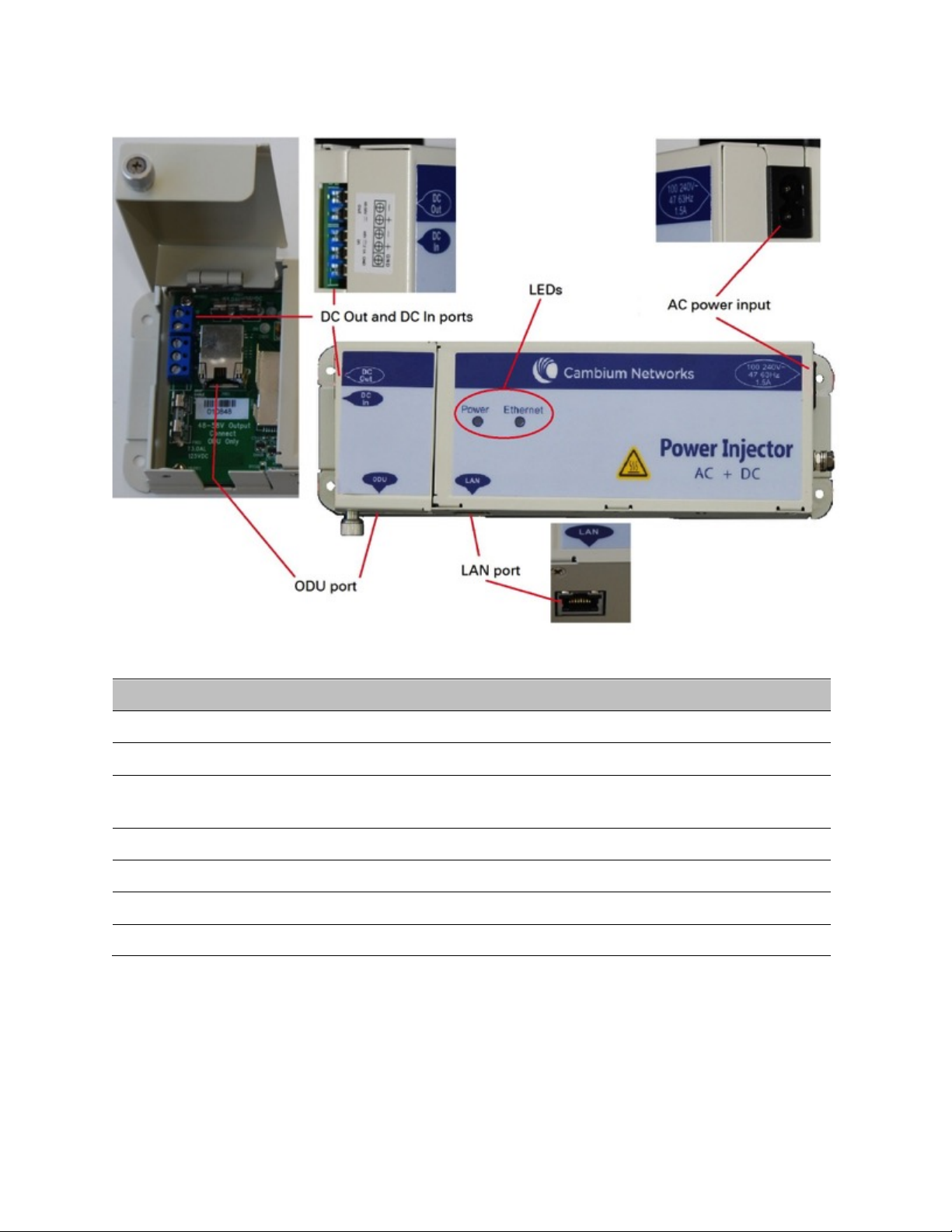
Chapter 2: System hardware
System Components
Page 2-22
Figure 5 AC+DC Enhanced Power Injector interfaces
Table 22 AC+DC Enhanced Power Injector interface functions
Interface
Function
100-240V 47-63Hz 1.5A
AC power input (main supply)
DC In
Alternative DC power supply input
DC Out
DC power output to a second PSU (for power supply redundancy) or
to a NIDU
ODU
RJ45 socket for connecting Cat5e cable to ODU
LAN
RJ45 socket for connecting Cat5e cable to network
Power (green) LED
Power supply detection
Ethernet (yellow) LED
Ethernet traffic detection
-48 V DC Power Injector
The DC Power Injector interfaces are shown in Figure 6 and described in Table 23.
Page 80
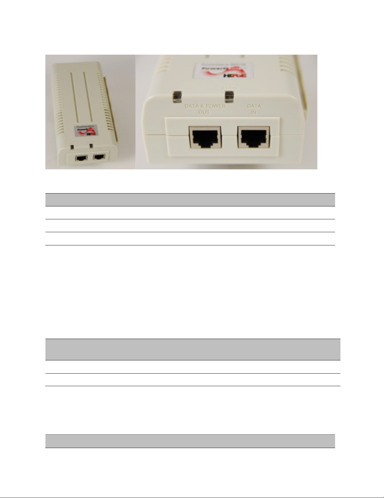
Chapter 2: System hardware
System Components
Page 2-23
Figure 6 -48 V DC Power Injector interfaces
Table 23 -48V DC Power Injector interfaces
Interface
Function
DC input
36 to 60V, 2A
RJ 45 Sockets
Two (Data In and Data & Power Out)
LEDs
Two (AC and Port)
Power supply – PMP/PTP 450
The PMP/PTP 450 support powering from the following powering sources:
• Gigabit Enet Capable Power Supply - 30VDC, 15W
• Power Supply,120W 30VDC AT 60C 100-240VAC EL5
PSU part numbers
Table 24 PSU part numbers for PMP/PTP 450
Cambium description
Cambium part
number
Gigabit Enet Capable Power Supply - 30VDC, 15W
N000900L001A
Power Supply,120W 30VDC AT 60C 100-240VAC EL5
ACPS120WA
Gigabit Enet Capable Power Supply
The Gigabit Enet Capable power supply interfaces are described in Table 25.
Table 25 –Gigabit Enet Capable power supply
Interface
Function
Page 81

Chapter 2: System hardware
System Components
Page 2-24
AC Input
90-264 VAC, 0.5A rms @120VAC/ 0.25A rms @240VAC, 47 to 63 Hz
DC Output
30.0 Vdc +/-5%, 15W, 500 mA max
RJ 45 Sockets
Two (Data In and Data & Power Out)
LEDs
Green, :LED Intensity determined by Level 5 efficiency
Power Supply -120 W/30 VDC
The power supply 120W/30VDC interfaces are described in Table 26.
Table 26 -120 W/30 VDC power supply
Interface
Function
AC Input
90-264 VAC, 3A rms @115VAC/ 1.5A rms @230VAC, 47 to 63 Hz
DC Output
30.0 Vdc +/-5%, 120W, 4 A max
RJ 45 Sockets
Two (Data In and Data & Power Out)
ODU mounting brackets & accessories
The list of supported brackets is provided in Table 27.
• The "Tilt bracket assembly" is the recommended bracket for the AP, SM or BH integrated units.
• The "Mounting Bracket (Connectorized)" can be used where a low profile and ease of assembly
of Connectorized AP, SM or BH is required.
• The "Mounting Bracket (Integrated)" provide a wider range of adjustment for AP, SM and BH
integrated devices.
Table 27 Accessories part numbers
Cambium description
Cambium part
number
Mounting brackets
Tilt Bracket Assembly
N000045L002A
Mounting Bracket (Integrated)
N000065L031A
Mounting Bracket (Connectorized)
N000065L032A
Miscellaneous
Ethernet cable adapter for CMM4
N000045L001A
Page 82

Chapter 2: System hardware
System Components
Page 2-25
Lightning protection
The PMP/PTP 450i Series supports the lightning protection units listed in Table 28.
The LPU offers the highest level of protection and is the recommended device. Where low cost
deployment is essential, for example for SM in residential application, the Gigabit Surge
Suppressor may be used instead.
Table 28 Lightning protection part numbers
Cambium description
Cambium part
number
LPU and Grounding Kit (1 kit per ODU)
C000065L007A
Gigabit Surge Suppressor (56V)
C000000L033A
Page 83
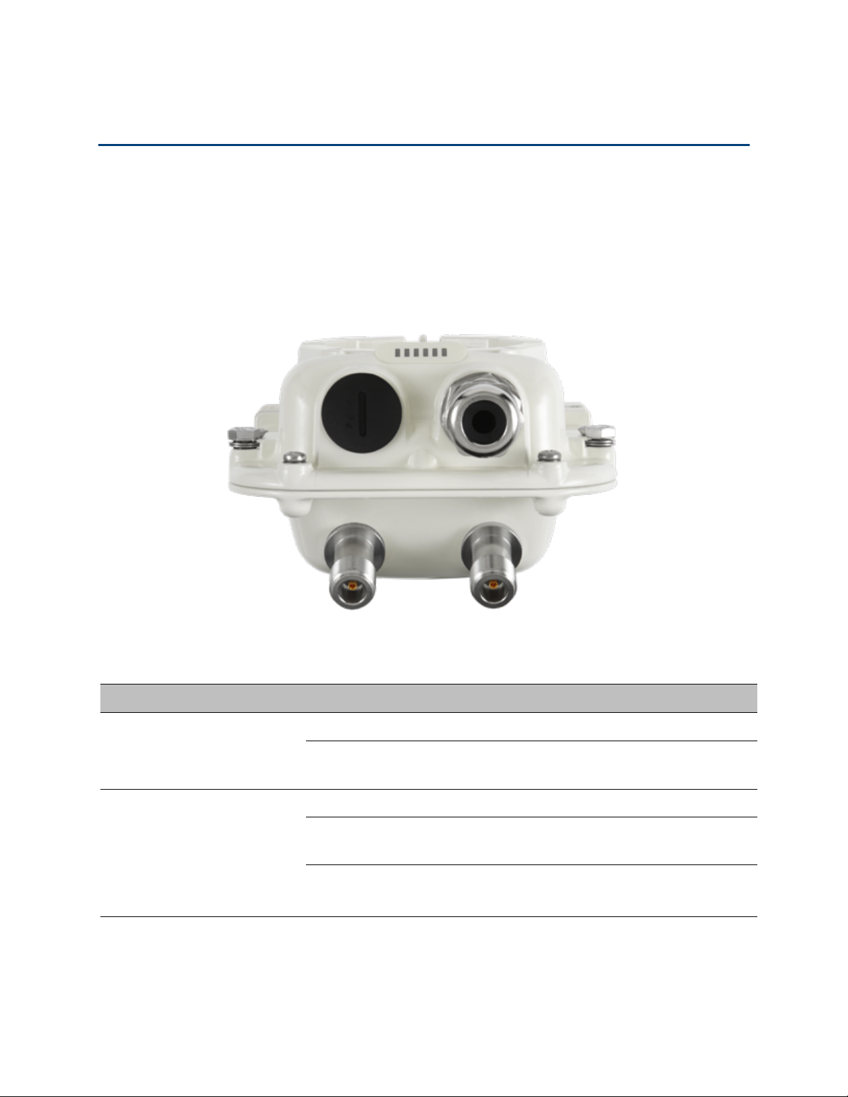
Chapter 2: System hardware
Cabling and lightning protection
Page 2-26
Cabling and lightning protection
ODU interfaces – PMP/PTP 450i
The Ethernet and Sync/AUX ports are on the rear of the integrated and connectorized ODUs
(Figure 7). These interfaces are described in Table 29.
Figure 7 ODU rear interfaces
Table 29 ODU rear interfaces
Port name
Connector
Interface
Description
Main PSU
RJ45
PoE input
Power over Ethernet (PoE).
10/100/1000BASE-T
Ethernet
Data
Sync/AUX
RJ45
10/100/100BASE-T Ethernet
Data (see Note below)
PoE output
Standard IEEE802.3at PoE. (see
Note below)
Sync input/output
Connection and powering of UGPS
Sync input
Page 84
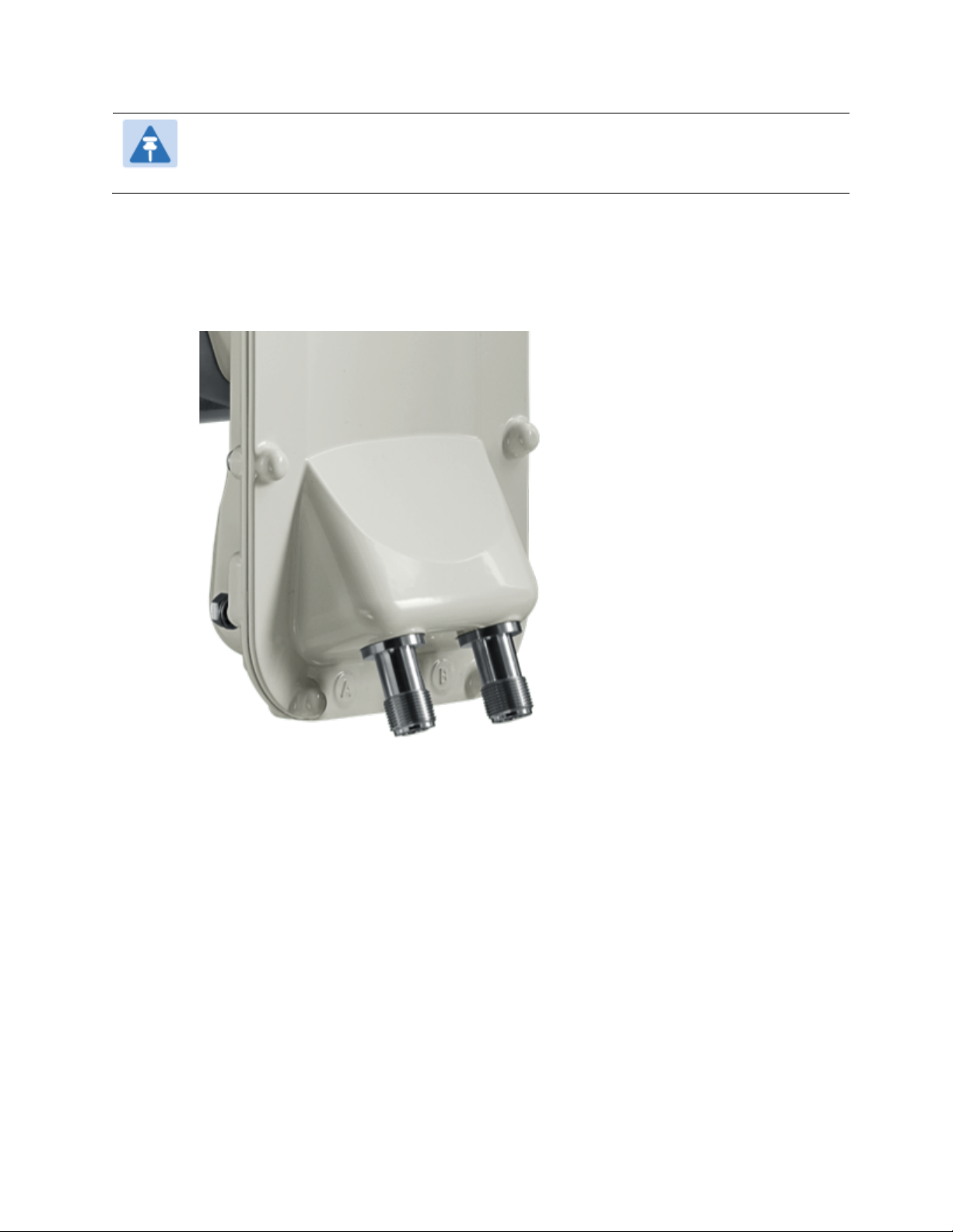
Chapter 2: System hardware
Cabling and lightning protection
Page 2-27
Note
The Sync/AUX port Data and PoE output capability are not supported in this firmware
release 14.0.
The front of the connectorized ODU (Figure 8 Connectorized ODU antenna interfaces) provides N
type female connectors for RF cable interfaces to antennas with ports A and B for vertical and
horizontal polarization respectively.
Figure 8 Connectorized ODU antenna interfaces
Ethernet standards and cable lengths
All configurations require a copper Ethernet connection from the ODU (Ethernet port) to the PoE.
Table 30 specifies, for each type of PSU and configuration, the maximum permitted PSU drop
cable length.
Page 85

Chapter 2: System hardware
Cabling and lightning protection
Page 2-28
Table 30 PSU drop cable length restrictions
System configuration
Maximum cable length (m/ft)
Power supply
PoE powered
device on
AUX/SYNC port
(see Note below)
From power
supply to ODU
From ODU to PoE
device on AUX/SYNC
port (see Note
below)
AC Power Injector (60W)
None
100 m
N/A
IEEE 802.3at Type 2
100 m in total
AC+DC enhanced Power
Injector (90W)
None
100 m
N/A
IEEE 802.3at Type 2
100 m in total
-48 V DC power injector
None
100 m
N/A
IEEE 802.3at Type 2
100 m in total
CMM4 with 56 V supply
None
100 m
N/A
IEEE 802.3at Type 2
Not supported
IEEE802.3at compliant
supply
None
100 m
N/A
IEEE 802.3at Type 2
Not supported
Note
The Ethernet functionality and associated PoE output capability are not supported in
this firmware release.
The Ethernet connectivity for CMM4 requires the part “Ethernet cable adapter for
CMM4 – N000045L001A”.
Page 86
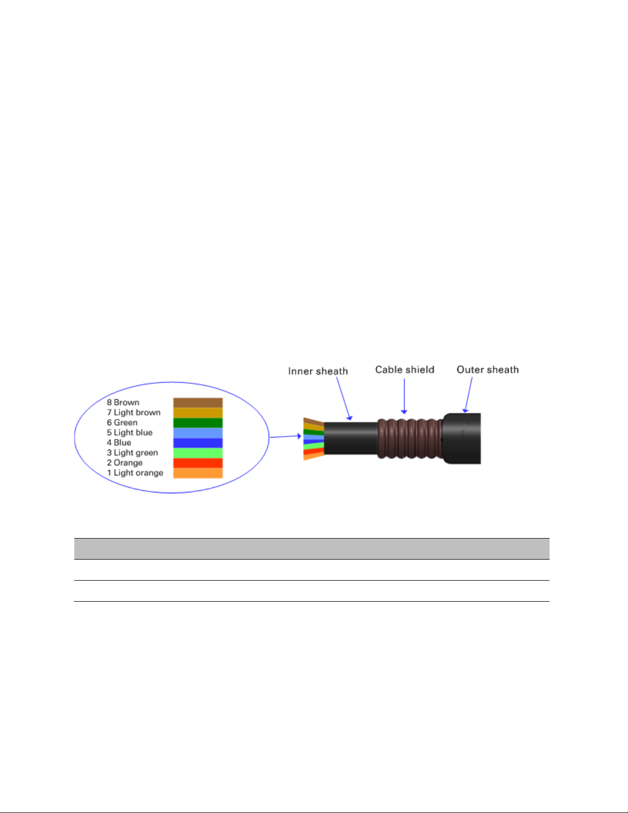
Chapter 2: System hardware
Cabling and lightning protection
Page 2-29
Outdoor copper Cat5e Ethernet cable
Outdoor Cat5e cable is used for all connections that terminate outside the building. For example,
connections between the ODU, surge suppressors (if installed), UGPS receivers (if installed) and
the power supply injector. This is known as a “drop cable” (Figure 9).
The following practices are essential to the reliability and longevity of cabled connections:
• Use only shielded cables and connectors to resist interference and corrosion.
• For vertical runs, provide cable support and strain relief.
• Include a 2 ft (0.6 m) service loop on each end of the cable to allow for thermal expansion and
contraction and to facilitate terminating the cable again when needed.
• Include a drip loop to shed water so that most of the water does not reach the connector at the
device.
• Properly crimp all connectors.
• Use dielectric grease on all connectors to resist corrosion.
Order Superior Essex type BBDGe cable from Cambium Networks (Table 31). Other lengths of this
cable are available from Superior Essex.
Figure 9 Outdoor drop cable
Table 31 Drop cable part numbers
Cambium description
Cambium part number
1000 ft Reel Outdoor Copper Clad CAT5E
WB3175
328 ft (100 m) Reel Outdoor Copper Clad CAT5E
WB3176
Page 87

Chapter 2: System hardware
Cabling and lightning protection
Page 2-30
Main Ethernet port
The PoE cable pinout diagram for Main port is given below.
Table 32 Main port PoE cable pinout
RJ45
pin
Interface
Ethernet
description
PoE input
description
1
1000 BaseT
Ethernet with
PoE In
+TxRx0
+Ve or -Ve
2 –TxRx0
3 +TxRx1
+Ve or –Ve
6 –TxRx1
5 –TxRx2
+Ve or –Ve
4 +TxRx2
7 +TxRx3
+Ve or –Ve
8 –TxRx3
Note
The PoE input on the Main port accepts any polarity as long as there is at least one pair
at +Ve and at least one at –Ve.
Aux port
Table 33 Aux port PoE cable pinout
RJ45
pin
Interface
Signal description
PoE output
description
1
100 BaseT
Ethernet with
PoE Out (see
note below)
+TxRx0
-Ve
2
–TxRx0
3
+TxRx1
+Ve
6
–TxRx1
5
GPS and
alignment tone
GPS power out, Alignment
tone out, GPS data out
N/A
4
GPS data in
7
GPS 0v
8
GPS Sync in
Page 88
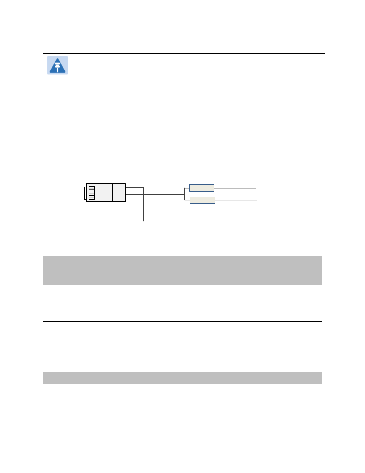
Chapter 2: System hardware
Cabling and lightning protection
Page 2-31
Note
Only alignment and sync functionalities are supported on the Aux port in current
release 14.0.
Aux port to alignment tone headset wiring
A standard 32 ohms stereo headset can be connected to the AUX port to use the audio alignment
tool. The diagram of the adapter is provided in Figure 10. The recommended values for both
resistors are 220 ohm, 0.25W. Different resistor value can be used to optimize the level of the audio
signal depending on the headset characteristics and the level of ambient noise
Figure 10 Alignment Tone Cable
Table 34 Aux port PoE cable pinout
RJ45 pin
(AUX port)
Signal description
Serial component
Jack socket
(to jack plug of
headset)
5
Alignment tone out
220 ohms resistor
Ring
220 ohm resistor
Tip
7
GPS 0v
None
Sleeve
Alternatively, a readymade headset adapter can be ordered from Best-Tronics
(http://btpa.com/Cambium-Products/) with the following part number:
Table 35 Alignment tone adapter third party product details
Reference
Product description
BT-1277
Headset alignment cable for the Cambium Networks PMP450i and
PTP450i product lines
220 Ω
220 Ω
Resistors
Pin 7
Pin 4
Left / tip
Right / ring
Sleeve /Common
#8
Page 89
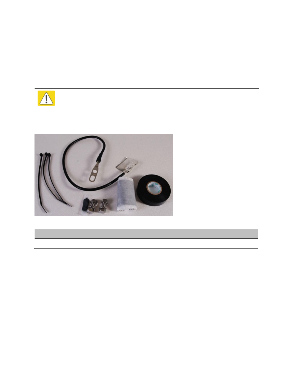
Chapter 2: System hardware
Cabling and lightning protection
Page 2-32
Cable grounding kit
Copper drop cable shields must be bonded to the grounding system in order to prevent lightningstrike arcing (resulting in fire risk and damage to equipment).
One grounding kit (Figure 11) is required for each grounding point on the PSU. Order cable
grounding kits from Cambium Networks (Table 36).
Caution
To provide adequate protection, all grounding cables must be a minimum size of 10
mm2 csa (8AWG), preferably 16 mm2 csa (6AWG), or 25 mm2 csa (4AWG).
Figure 11 Cable grounding kit
Table 36 Cable grounding kit part numbers
Cambium description
Cambium part number
Cable Grounding Kits For 1/4" And 3/8" Cable
01010419001
Lightning protection unit (LPU) and grounding kit
PMP/PTP 450i LPUs provide transient voltage surge suppression for ODU installations. Each PSU
requires two LPUs, one near the ODU and the other near the linked device, usually at the building
entry point (Table 37).
Page 90
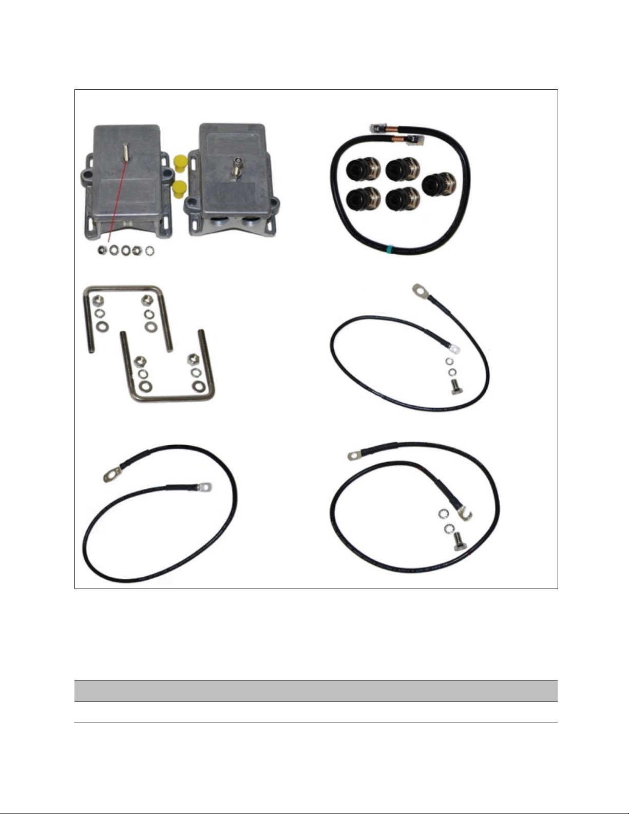
Chapter 2: System hardware
Cabling and lightning protection
Page 2-33
Table 37 LPU and grounding kit contents
Lightning protection units (LPUs)
LPU grounding point nuts and washers
ODU to top LPU drop cable (600 mm)
EMC strain relief cable glands
U-bolts, nuts and washers for mounting LPUs
ODU to top LPU ground cable (M6-M6)
Bottom LPU ground cable (M6-M10)
ODU to ground cable (M6-M10
One LPU and grounding kit (Table 37) is required for the PSU drop cable connection to the ODU. If
the ODU is to be connected to an auxiliary device, one additional LPU and grounding kit is
required for the Aux drop cable. Order the kits from Cambium Networks (Table 38).
Table 38 LPU and grounding kit part number
Cambium description
Cambium part number
PMP/PTP 450i LPU and Grounding Kit (One Kit Per End)
C000065L007
Page 91

Chapter 2: System hardware
Antennas and antenna cabling
Page 2-34
Antennas and antenna cabling
Antenna requirements
Each connectorized ODU requires one external antenna (normally dual-polar).
For connectorized units operating in the USA or Canada 4.9 GHz, 5.1 GHz, 5.2 GHz, 5.4 GHz, 5.8
GHz or 900 MHz bands, choose external antennas which are recommended by Cambium
Networks. Do not install any other antennas.
Supported external AP antennas
The recommended AP external antennas are listed in Table 39.
Table 39 List of AP external antennas
Cambium description
Cambium part
number
5 GHz Horizontal and Vertical Polarization Antenna for 90 Degree
Sector
85009324001
5 GHz Horizontal and Vertical Polarization Antenna for 60 Degree
Sector
85009325001
900 MHz16 12 dBi 90 degree Sector Antenna (Dual Slant)
N009045D002A
900 MHz 13 dBi 65 degree Sector Antenna (Dual Slant)
N009045D001A
Note
LINKPlanner, Cambium Networks planning tool, contains an up-to-date, exhaustive
list of antennas that can be used with Cambium Products.
Supported external SM antennas
The recommended PMP 450(i) SM external antennas is listed in Table 40.
Table 40 PMP 450(i) SM antenna
Cambium description
Cambium part
number
900 MHz 12 dBi gain directional antenna (Dual Slant)
N009045D003A
16
900 MHz support planned for future release.
Page 92

Chapter 2: System hardware
Antennas and antenna cabling
Page 2-35
RF cable and connectors
RF cable of generic type LMR-400 is required for connecting the ODU to the antenna. N type male
connectors are required for connecting the RF cables to the connectorized ODU. Two connectors
are required per ODU. Use weatherproof connectors, preferably ones that are supplied with
adhesive lined heat shrink sleeves that are fitted over the interface between the cable and
connector. Order CNT-400 RF cable and N type male connectors from Cambium Networks (Table
41).
Table 41 RF cable and connector part numbers
Cambium description
Cambium part number
50 Ohm Braided Coaxial Cable - 75 meter
30010194001
50 Ohm Braided Coaxial Cable - 500 meter
30010195001
RF Connector, N, Male, Straight for CNT-400 Cable
09010091001
Antenna accessories
Connectorized ODUs require the following additional components:
• Cable grounding kits: Order one cable grounding kit for each grounding point on the antenna
cables. Refer to Lightning protection unit (LPU) and grounding kit on 2-32
• Self-amalgamating and PVC tape: Order these items to weatherproof the RF connectors
• Lightning arrestors: When the connectorized ODU is mounted indoors, lightning arrestors (not
LPUs) are required for protecting the antenna RF cables at building entry. One arrestor is
required per antenna cable. One example of a compatible lightning arrestor is the Polyphaser
LSXL-ME or LSXL (not supplied by Cambium Networks).
RJ45 connectors and spare glands
RJ45 connectors are required for plugging Cat5e cables into ODUs, LPUs, PoEs and other devices.
Order RJ45 connectors and crimp tool from Cambium Networks (Table 42).
The ODU is supplied with one environmental sealing gland for the drop cable.
Figure 12 Cable gland
Page 93

Chapter 2: System hardware
Antennas and antenna cabling
Page 2-36
Table 42 RJ45 connector and spare gland part numbers
Cambium description
Cambium part number
Tyco/AMP, Mod Plug RJ45, 100 pack
WB3177
Tyco/AMP Crimp Tool
WB3211
RJ-45 Spare Grounding Gland - PG16 size (Qty. 10)
N000065L033
Page 94
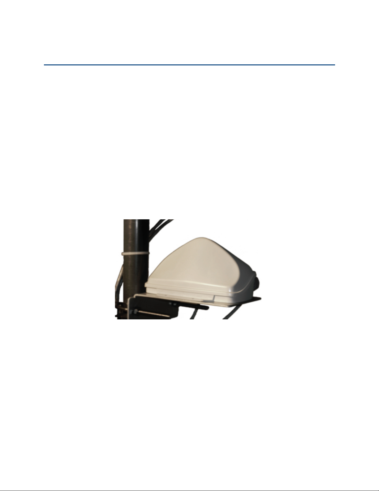
Chapter 2: System hardware
GPS synchronization
Page 2-37
GPS synchronization
GPS synchronization description
Cambium offers GPS synchronization to limit the network’s own self-interference. The Cluster
Management CMM provides Global Positioning System (GPS) synchronization to the Access Point
(AP) and all associated Subscriber Modules (SM). Network operators have a choice of UGPS and
CMM solutions to select the option that works best for the environment.
Universal GPS (UGPS)
The UGPS provides network synchronization for smaller networks where a CMM may not be cost
effective. The UGPS provides synchronization for one or two modules so that even remote areas at
the edge of the network can operate with synchronization for improved performance. The UGPS
works with all Cambium PMP radios. The UGPS has a small footprint and is easy to deploy.
Figure 13 UGPS
CMM4 (Rack
Mount)
The Cluster Management Module (CMM) is the heart of the Cambium system’s synchronization
capability, which allows network operators to reuse frequencies and add capacity while ensuring
consistency in the quality of service to customers.
For operators who prefer indoor CMM mounting, Cambium offers the Rack-Mounted Cluster
Management Module 4. The unit is designed to be mounted onto a standard 19-inch
telecommunications rack and to allow the Cambium CMM4 to be co-located with other
telecommunications equipment.
Page 95
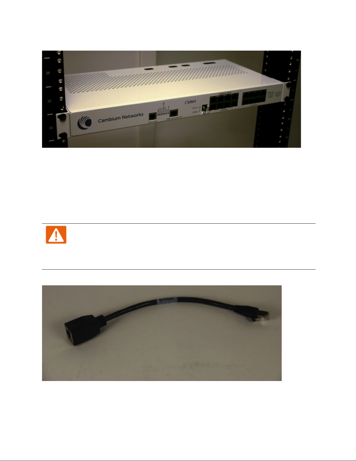
Chapter 2: System hardware
GPS synchronization
Page 2-38
Figure 14 CMM4 (Rack Mount)
The CMM4 has two DC power inputs, one 29 V and one 56V. It can be used to power and
synchronize both 29V legacy products such as PMP 450 and 56V products such as PMP 450i
simultaneously.
If the 29V legacy products are connected to the CMM4, a 29V power supply needs to be connected.
If PMP/PTP 450(i) are connected to a CMM4, it needs to be connected with an external 56V PSU".
The CMM4 supports having two of the 56V and two of the 24V supplies for redundancy.
Warning
PMP 450 and PMP 450i require different wiring between the CMM4 and device. If a
PMP450 is replaced by a PMP 450(i) and the existing drop cable needs to be re-used,
the adapter "CMM4 56V power adapter, #N000045L001A" must be used between the
CMM4 and the existing drop cable.
Figure 15 CMM4 56V power adapter
Page 96
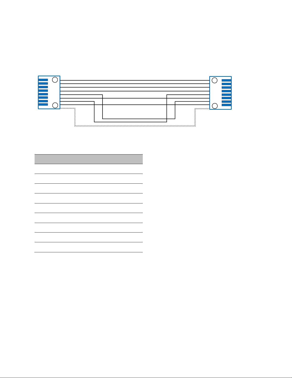
Chapter 2: System hardware
GPS synchronization
Page 2-39
CMM4 56V power adapter cable pinout
Figure 16 CMM4 power adapter cabling diagram
Table 43 CMM4 power adapter cable pinout
Plug J1 pin
Jack J2 pin
1 1 2 2 3
3
4
4
5
7
6
6
7 5 8
8
Screen
Screen
1
8 1 8
J1
J2
RJ45 Plug
RJ45 Jack
5
7
5
7
Shield
Page 97
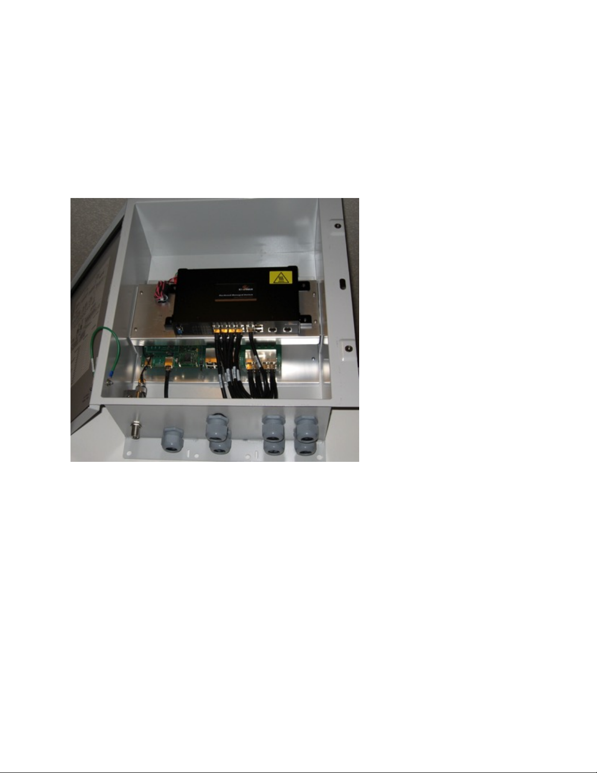
Chapter 2: System hardware
GPS synchronization
Page 2-40
CMM4
(Cabinet
with
switch)
Designed to deliver consistent and reliable wireless broadband service, the PMP/PTP system
gracefully scales to support large deployments. The cluster management module is the heart of
the system’s synchronization capability which allows network operators to re-use frequencies and
add capacity while ensuring consistency in the quality of service to customers. As a result,
subscribers can experience carrier-grade service even at the outer edge of the network.
Figure 17 CMM4 (Cabinet with switch)
CMM4
(Cabinet
without
switch)
This CMM includes all of the functionality listed above but there is no switch. This provides the
network operator the flexibility to use the switch of their choice with the power and
synchronization capabilities of the CMM4.
CMM4/CMMmicro
The CMM3 or CMMmicro (Cluster Management Module micro) provides power, GPS timing, and
networking connections for an AP cluster. The CMM3 is configurable through a web interface.
Page 98
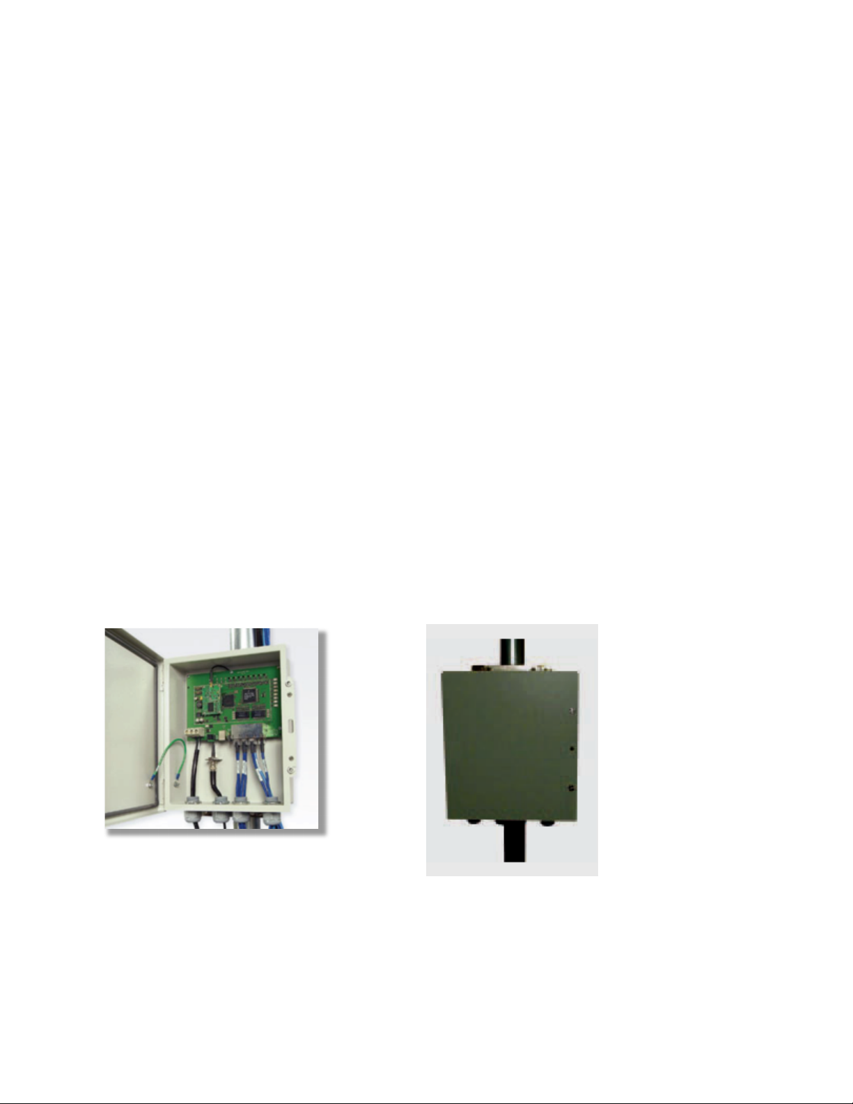
Chapter 2: System hardware
GPS synchronization
Page 2-41
The CMM3 contains an 8-port managed switch that supports Power over Ethernet (PoE) on each
port and connects any combination of APs, BHMs, BHSs, or Ethernet feed. The Cambium fixed
wireless broadband IP networks PoE
differs from
IEEE Standard 803.3af PoE, and the two should
not be intermixed. The CMM3 can auto-negotiate speed to match inputs that are either 100Base-TX
or 10Base-T, and either full duplex or half duplex, where the connected device is set to autonegotiate. Alternatively, these parameters are settable.
A CMM3 requires only one cable, terminating in an RJ-45 connector, for each connected module to
distribute
• Ethernet signaling.
• power to as many as 8 co-located modules—APs, BHMs, or BHSs. Through a browser
interface to the managed switch, ports can be powered or not.
• sync to APs and BHMs. The CMM3 receives 1-pulse per second timing information from
Global Positioning System (GPS) satellites through an antenna (included) and passes the
timing pulse embedded in the 24-V power to the connected modules.
GPS status information is available at the CMM3, however
• CMM3 provides time and date information to BHMs and APs if both the CMMmicro is
operating on CMMmicro Release 2.1 or later and the AP/BHM is operating on System
Release 4.2 or later. See Error! Reference source not found. on Page Error!
Bookmark not defined..
• CMM3
does not
provide time and date information to BHMs and APs if either the CMM3 is
operating on a release earlier than CMMmicro Release 2.1 or the AP/BHM is operating on a
release earlier than System Release 4.2.
A CMM3/CMM4 is shown in Figure 18 and Figure 19.
Figure 18 CMM3
Figure 19 Pole mounted CMM3
Page 99

Chapter 2: System hardware
Ordering the components
Page 2-42
Ordering the components
This section describes how to select components for PMP/PTP 450(i) Greenfield network or
PMP/PTP 450i network migration. It specifies Cambium part numbers for PMP/PTP 450i
components.
Table 44 PMP/PTP 450i components
Cambium description
Cambium part
number
PMP 450i AP
5 GHz PMP 450i Connectorized Access Point (ROW)
C050045A001A
5 GHz PMP 450i Connectorized Access Point (FCC)
C050045A002A
5 GHz PMP 450i Connectorized Access Point (EU)
C050045A003A
5 GHz PMP 450i Connectorized Access Point (DES Only)
C050045A004A
5 GHz PMP 450i Connectorized Access Point (IC)
C050045A015A
5 GHz PMP 450i Integrated Access Point, 90 degree (ROW)
C050045A005A
5 GHz PMP 450i Integrated Access Point, 90 degree (FCC)
C050045A006A
5 GHz PMP 450i Integrated Access Point, 90 degree (EU)
C050045A007A
5 GHz PMP 450i Integrated Access Point, 90 degree (DES Only)
C050045A008A
5 GHz PMP 450i Integrated Access Point, 90°sector antenna (IC)
C050045A016A
900 MHz PMP 450i Connectorized Access Point
C009045A001A
PMP 450i SM
5 GHz PMP 450i Connectorized Subscriber Module
C050045C001A
5 GHz PMP 450i SM, Integrated High Gain Antenna
C050045C002A
900 MHz PMP 450i Connectorized Subscriber Module
C009045C001A
PTP 450i
5 GHz PTP 450i END, Connectorized (ROW)
C050045B001A
5 GHz PTP 450i END, Integrated High Gain Antenna (ROW)
C050045B002A
5 GHz PTP 450i END, Connectorized (FCC)
C050045B003A
5 GHz PTP 450i END, Integrated High Gain Antenna (FCC)
C050045B004A
5 GHz PTP 450i END, Connectorized (EU)
C050045B005A
5 GHz PTP 450i END, Integrated High Gain Antenna (EU)
C050045B006A
Page 100

Chapter 2: System hardware
Ordering the components
Page 2-43
5 GHz PTP 450i END, Connectorized (DES Only)
C050045B007A
5 GHz PTP 450i END, Integrated High Gain Antenna (DES only)
C050045B008A
900 MHz PMP 450i Connectorized Backhaul
C009045B001A
Power supplies
Power supply, 60 W, 56 V with Gbps support
N000065L001B
AC+DC Enhanced Power Injector
C000065L002B
Ethernet cable adapter for CMM4
N000045L001A
Power over Ethernet midspan, 60 W, -48 VDC Input
N000000L036A
Accessories
Gigabit Surge Suppressor (56V)
C000000L033A
LPU and Grounding Kit (1 kit per ODU)
C000065L007A
Mounting brackets
Tilt Bracket Assembly
N000045L002A
Mounting Bracket (Integrated)
N000065L031A
Mounting Bracket (Connectorized)
N000065L032A
Accessories
5 GHz Horizontal and Vertical Polarization Antenna for 90 Degree
Sector
85009324001
5 GHz Horizontal and Vertical Polarization Antenna for 60 Degree
Sector
85009325001
900 MHz Horizontal and Vertical Polarization Antenna for 90 Degree
Sector
N009045D002A
900 MHz Horizontal and Vertical Polarization Antenna for 65 Degree
Sector
N009045D001A
900 MHz 12 dBi gain directional antenna (Dual Slant)
N009045D003A
50 Ohm Braided Coaxial Cable - 75 meter
30010194001
50 Ohm Braided Coaxial Cable - 500 meter
30010195001
RF Connector, N, Male, Straight for CNT-400 Cable
09010091001
Blanking Plug Pack (Qty 10)
N000065L036A
Extended Warranty
PMP 450 AP Extended Warranty, 1 Additional Year
SG00TS4009A
PMP 450 AP Extended Warranty, 2 Additional Years
SG00TS4017A
 Loading...