

Page 1
LTR20121002, Rev. A
12/30/11
Page 2

Preparing for Your New Inground Spa
Diverter Knobs.......................29
Inground Spa Installation Checklist.......4
Planning the Best Location For Your Spa...4
Planning the Best Place for the Outdoor
Equipment Pack.......................5
Inground Spa Site Preparation...........5
Spa Shell Dimensions and Side Views .....6
Electrical Requirements – US and Canada 13
GFCI Wiring Diagram .................14
Electrical Installation -- Europe.........15
RCD Wiring Diagram ..................16
Installing the Inground Shell ...........17
Equipment Pack Plumbing Connections...18
Plumbing Connections ................18
Electrical and Electronic Connection .....20
Pouring the Deck.....................23
9800 Electronic Control Operation
Clear Water Plan
The Key to Clear Water ................30
Testing and Adjusting Spa Water........31
Sanitation...........................32
Filter Cleaning .......................33
Bather Load . . . . . . . . . . . . . . . . . . . . . . . . .34
Starting the Spa with Fresh Water.......34
Maintenance Schedule ................35
Cleaning and Maintenance
Removing and Reseating the Pillows.....36
Spa Cover...........................36
Draining Your Spa ....................37
Cleaning and Replacing the Filter........37
Winterizing (Cold Climate Draining) .....37
Cleaning Your Spa ....................38
Appendix
Diagnostic Messages..................27
Adjustable Jets ......................29
Copyright 2011 LMS, Inc. All rights reserved. Duplication without written consent is strictly
prohibited.
Cal Spas® is a registered trademark.
Due to continuous improvement programs, all models, operation, and/or specications are
subject to change without prior notice.
Replacement Parts ...................39
Warranty ...........................39
LTR20121002, Rev. A
12/30/11
100-1074
CONTACT INFORMATION
For customer service, please contact
your authorized dealer immediately. If
you need additional information and/
or assistance, please contact:
LMS Customer Service Department
1462 East Ninth Street
Pomona, CA 91766.
Toll Free: 1-800-CAL-SPAS
Fax: 1-909-629-3890
www.calspas.com
Page 3
www. c al sp a s. co m
Important Safety Instructions
When installing and using this electrical equipment,
always follow basic safety precautions. Following
these instructions will help make your rst spa session a pleasurable one.
104˚F (40˚C) are considered safe for a healthy
adult. Lower water temperatures are recommended
for young children and when spa use exceeds 10
minutes.
3
Read This First!
READ AND FOLLOW ALL INSTRUCTIONS
NOTE: A licensed electrician may be required to upgrade your standard receptacle and/or circuit breaker.
DANGER -- RISK OF ACCIDENTAL DROWNING: Do not allow children to be in or around a spa
unless a responsible adult supervises them. Keep
the spa cover on and locked when not in use. See
instructions enclosed with your cover for locking procedures.
DANGER -- RISK OF INJURY: The suction ttings
in this spa are sized to match the specic water ow
created by the pump. Should the need arise to re-
place the suction ttings, or the pump, be sure the
ow rates are compatible.
DANGER -- RISK OF INJURY: Never operate the
spa if the suction tting or lter baskets are broken
or missing.
DANGER -- RISK OF INJURY: Never replace a
suction tting with one that is rated less than the
ow rate marked on the original suction tting.
DANGER -- RISK OF ELECTRIC SHOCK: Install
the spa at least ve feet (1.5 meters) from all metal
surfaces. As an alternative, a spa may be installed
within 5 feet of metal surfaces if each metal surface
is permanently bonded by a minimum #8 AWG solid
copper conductor to the outside of the spa’s control
box.
DANGER -- RISK OF ELECTRIC SHOCK: Do
not permit any external electrical appliances, such
as lights, telephones, radios, televisions, and etc.,
within ve feet (1.5 meters) of the spa. Never attempt to operate any electrical device from inside
the spa. This does not apply to lights built in to the
spa as factory options from Cal Spas™.
WARNING -- RISK OF INJURY
The spa water should never exceed 104˚F (40˚C).
Water temperatures between 100˚F (38˚C) and
High water temperatures have a high potential for
causing fetal damage during pregnancy. Women
who are pregnant, or who think they are pregnant,
should always check with their physician prior to spa
usage.
The use of alcohol, drugs or medication before or
during spa use may lead to unconsciousness, with
the possibility of drowning.
Persons suffering from obesity, a medical history of
heart disease, low or high blood pressure, circulatory system problems or diabetes should consult a
physician before using the spa.
Persons using medications should consult a physician before using the spa since some medications
may induce drowsiness while others may affect
heart rate, blood pressure and circulation.
Hyperthermia Danger
Prolonged exposure to hot air or water can induce
hyperthermia. Hyperthermia occurs when the inter-
nal temperature of the body reaches a level 3˚F to
6˚F above the normal body temperature of 98.6˚F
(or 2˚C to 4˚C above 37˚C). While hyperthermia
has many health benets, it is important not to allow
your body’s core temperature to rise above 103˚F
(39.5˚C). Symptoms of excessive hyperthermia in-
clude dizziness, lethargy, drowsiness and fainting.
The effects of excessive hyperthermia may include:
Failure to perceive heat•
Failure to recognize the need to exit spa or hot •
tub
Unawareness of impending hazard•
Fetal damage in pregnant women•
Physical inability to exit the spa•
Unconsciousness•
WARNING: The use of alcohol, drugs, or medication can greatly increase the risk of fatal hyperthermia.
Inground Spas
LTR20121002, Rev. A
Page 4
www. c al sp a s. co m
4
Preparing for Your New Inground Spa
Most cities and counties require permits for exterior construction and electrical circuits. In addition, some
communities have codes requiring residential barriers such as fencing and/or self-closing gates on property to
prevent unsupervised access to the property by children. Your dealer can provide information on which permits
may be required and how to obtain them prior to the delivery of your Cal Spa.
Inground Spa Installation Checklist
Before Delivery
Planning the Best Location For Your Spa
Preparing for Your New Inground Spa
Safety First
Do not place your spa within 10 feet (3 m) of overhead power lines.
Make sure the spa is positioned so that access to the
equipment compartment and all side panels will not
be blocked. Be certain that your installation will meet
all city and local safety codes and requirements.
Consider How You Will Use Your Spa
How you intend to use your spa will help you determine where you should position it. For example,
will you use your spa for recreational or therapeutic
purposes? If your spa is mainly used for family recreation, be sure to leave plenty of room around it for
activity. If you will use it for relaxation and therapy,
you’ll probably want to create a specic mood around
it.
Plan for Your Environment
If you live in a region where it snows in the winter
or rains frequently, place the spa near a house entry.
By doing this, you will have a place to change clothes
and not be uncomfortable.
Consider Your Privacy
In a cold-weather climate, bare trees won’t provide
much privacy. Think of your spa’s surroundings during all seasons to determine your best privacy op-
Plan your delivery route
Choose a suitable location for the shell and
equipment pack
Excavate the hole
Install dedicated electrical supply
Install dedicated NG line for gas heater
After Delivery
Remove spa from shipping platform
Install shell in ground
Install equipment pack
Connect plumbing
Connect electrical components
Pour the deck
tions. Consider the view of your neighbors as well
when you plan the location of your spa.
Provide A View With Your Spa
Think about the direction you will be facing when
sitting in your spa. Do you have a special landscaped
area in your yard that you nd enjoyable? Perhaps
there is an area that catches a soothing breeze during the day or a lovely sunset in the evening.
Keep Your Spa Clean
Prevent dirt and contaminants from being tracked
into your spa by placing a foot mat at the spa’s entrance where the bather’s can clean their feet before
entering your spa. You may also consider keeping a
small water-lled basin nearby for bathers to rinse
their feet before entering your spa.
In planning your spa’s location, consider a location
where the path to and from the house can be kept
clean and free of debris.
Allow For Service Access
Many people choose to install a decorative structure
around their spa. If you are installing your spa with
any type of structure on the outside, such as a gazebo, remember to allow access for service. It is always
best to design special installations so that the spa can
still be accessed.
Inground Spas
LTR20121002, Rev. A
Page 5
www. c al sp a s. co m
Planning the Best Place for the Outdoor Equipment Pack
The Designer Spa series requires an external equipment pack. When locating the outdoor equipment
pack, you will want to consider the following:
The equipment pack must be located within a •
maximum of 15 feet from the spa.
owner’s manual for important location and safety
information.)
The equipment base and heater must be placed •
on either a 3 1/2” cement slab or 3” paving
stones.
5
Preparing for Your New Inground Spa
Ensure the equipment running its normal ltra-•
tion cycles does not make too much noise for spa
owners and/or neighbors.
Ensure the equipment can be easily serviced for •
lter cleaning and periodic inspections in the location chosen.
If you are using a gas heater, you will need to •
consider wind and drafts as well as heater ex-
haust for proper heater placement. (See heater
Inground Spa Site Preparation
Ensure there is enough room for the spa and •
equipment.
Plan for proper electrical and gas service to both •
the equipment area and spa side.
Ensure the required at, level foundation can be •
constructed in the area chosen.
The spa must be properly back-lled with wet •
sand, underneath and on all four sides.
Never place any spa in a sealed area. Water must •
be able either to be absorbed into the surrounding area or channeled away. Water build-up under and/or around the spa, will cause the spa to
oat out of the ground.
Grading Prior to Excavation
Selection of the Designer Spas site will determine
how much grading will have to be accomplished prior
to the actual dig for the spa. Naturally, a level area is
best because it will require the least amount of preparation for the dig, but in many cases there is no level
area, therefore, the site must be prepared to accept
the spa prior to dig. The spa site should be elevated
slightly higher than the surrounding area.
When dealing with slopes, the severity of the slope
will determine if retaining walls must be built in order
to have a level area for the spa. If the slope is relatively minor, contact your local building safety.
Site Excavation – Hard Bottom
For hard bottom placement for inground spas, you
will need a smooth and at concrete surface at least
Make sure the equipment area selected will not •
be in an area where water could run or stand.
If the area receives direct sunlight, you will want •
to provide some protection for the equipment
portion of the equipment pack.
The equipment pack and heater are delivered separately. Do not cover gas heaters unless properly vent-
ed. (See heater owner’s manual for important safety
information.)
4” thick as large as the bottom contact points. Be
sure not to seal the bottom off and making a sealed
box. You will need adequate water drainage for escape under the spa. A gravel beds around the concrete base will help with this.
Site Excavation – Sand Bottom
With the spa area and all elevations planned including your decided type of decking, you are now ready
to proceed with the dig. An ideal excavation is one
that is as close as possible to the dimensions of the
spa shell, but with the following rules in mind. The
excavation should be 2” to 4” deeper than the actual
spa for your sand bed. The sand bed is to level the
spa shell and provide a perfect support base with no
voids when the spa is lowered into the hole. Your
excavation should be approximately one foot longer
and one foot wider than the spa shell. This will allow
for a six inch over dig all the way around the spa once
it is in place. Additional hand excavation will be re-
quired to insure the skimmer will t in the excavation
when attached to the spa.
Sand or rock dust must be used to bed the shell into
the excavation and for backll. In no event is dirt to
be used. One of the easiest ways to know how much
sand is needed to be placed on the bottom of the
excavation is to set a grade stake at all four corners,
and one on each side of the center line in the bottom
of the hole. If there are areas that are deeper than
2” to 4”, these can be lled with sand and are of no
consequence.
Inground Spas
LTR20121002, Rev. A
Page 6
www. c al sp a s. co m
6
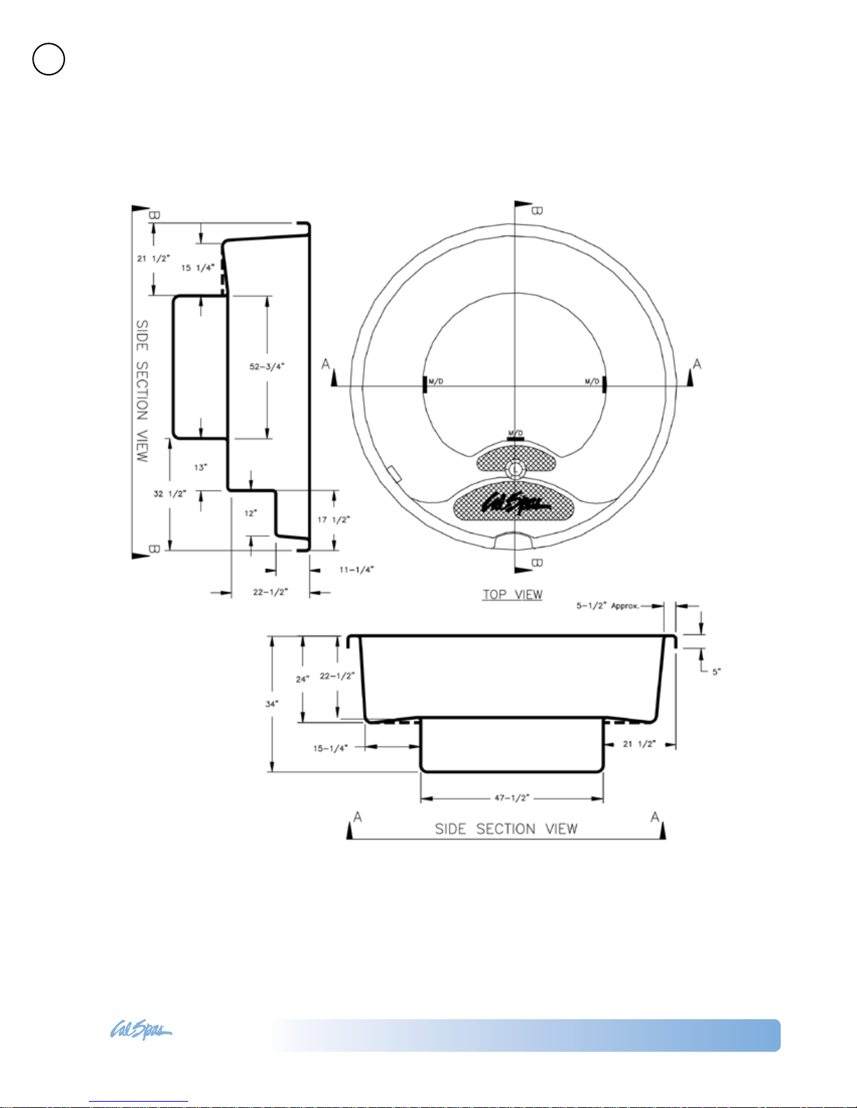
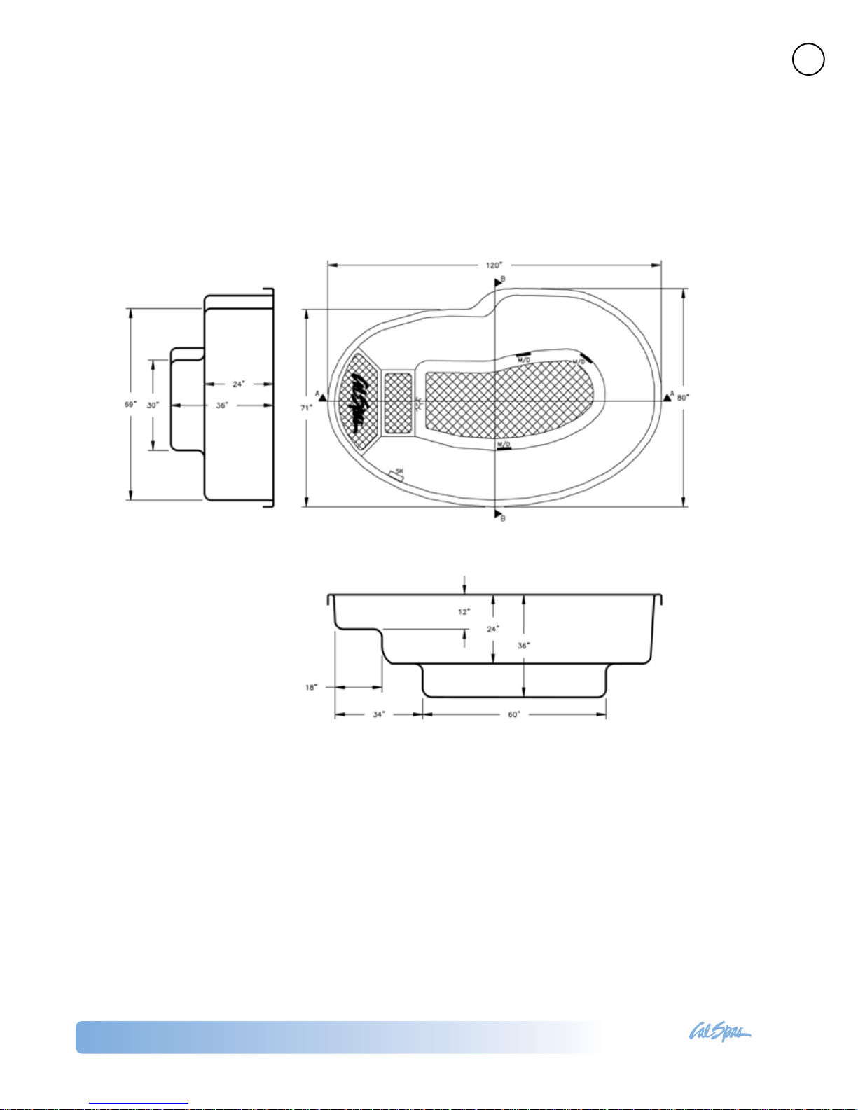
Spa Shell Dimensions and Side Views
IG-401
Preparing for Your New Inground Spa
Inground Spas
LTR20121002, Rev. A
Page 7
www. c al sp a s. co m
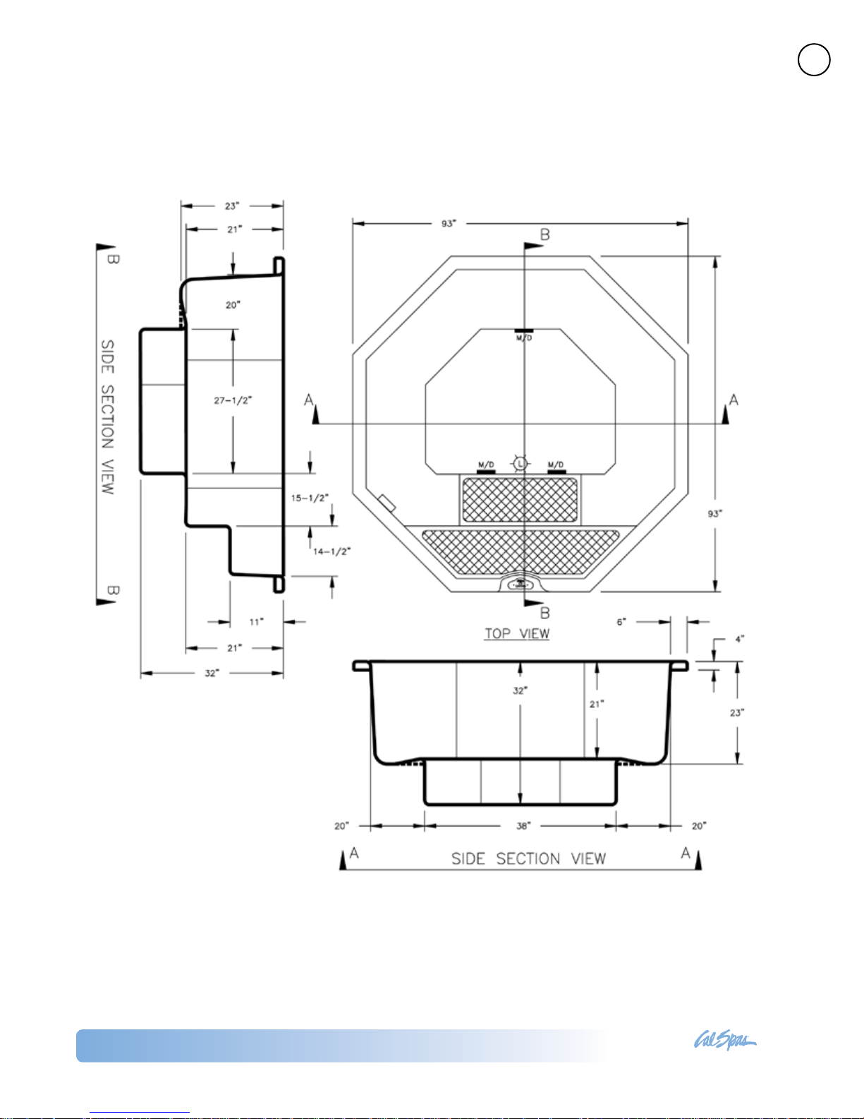
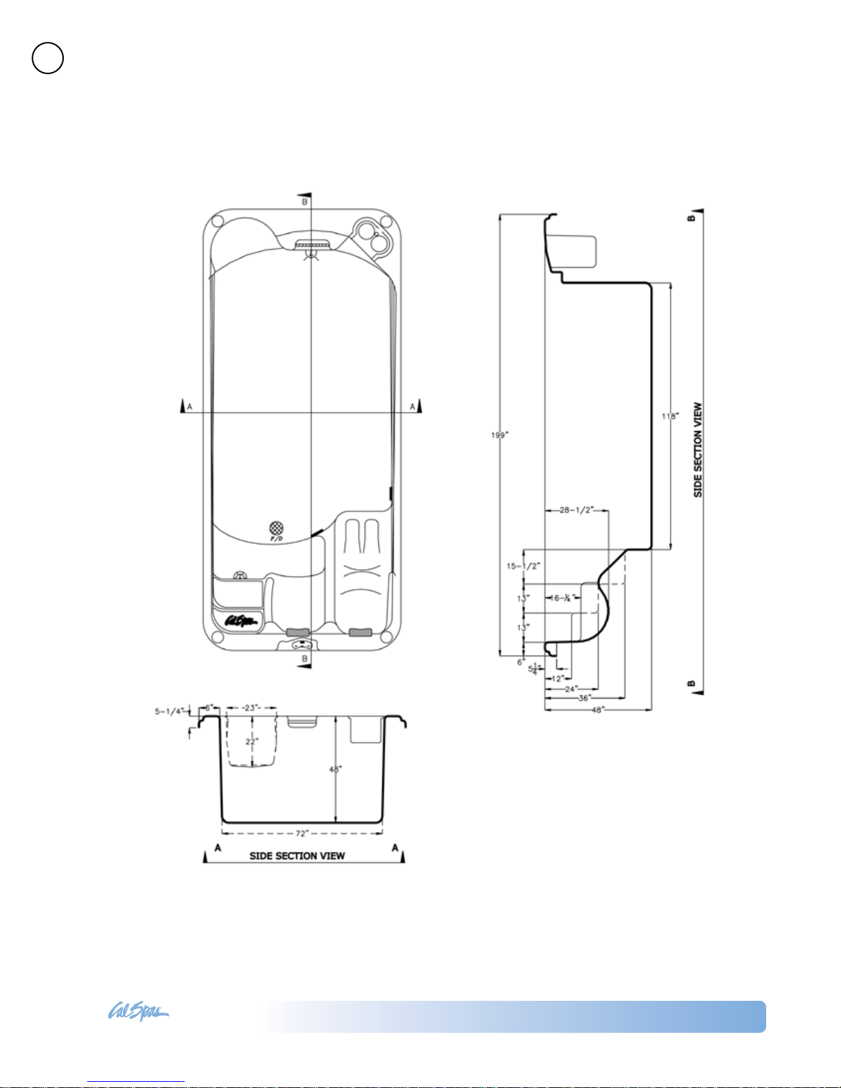
IG-402
7
Preparing for Your New Inground Spa
Inground Spas
LTR20121002, Rev. A
Page 8

www. c al sp a s. co m
8
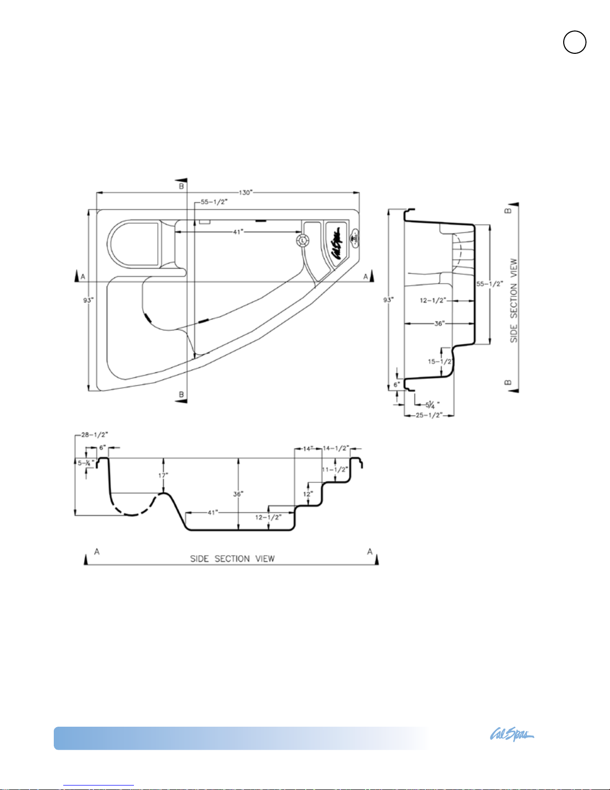
IG-403
Preparing for Your New Inground Spa
Inground Spas
LTR20121002, Rev. A
Page 9
www. c al sp a s. co m
IG-404
9
Preparing for Your New Inground Spa
Inground Spas
LTR20121002, Rev. A
Page 10
www. c al sp a s. co m
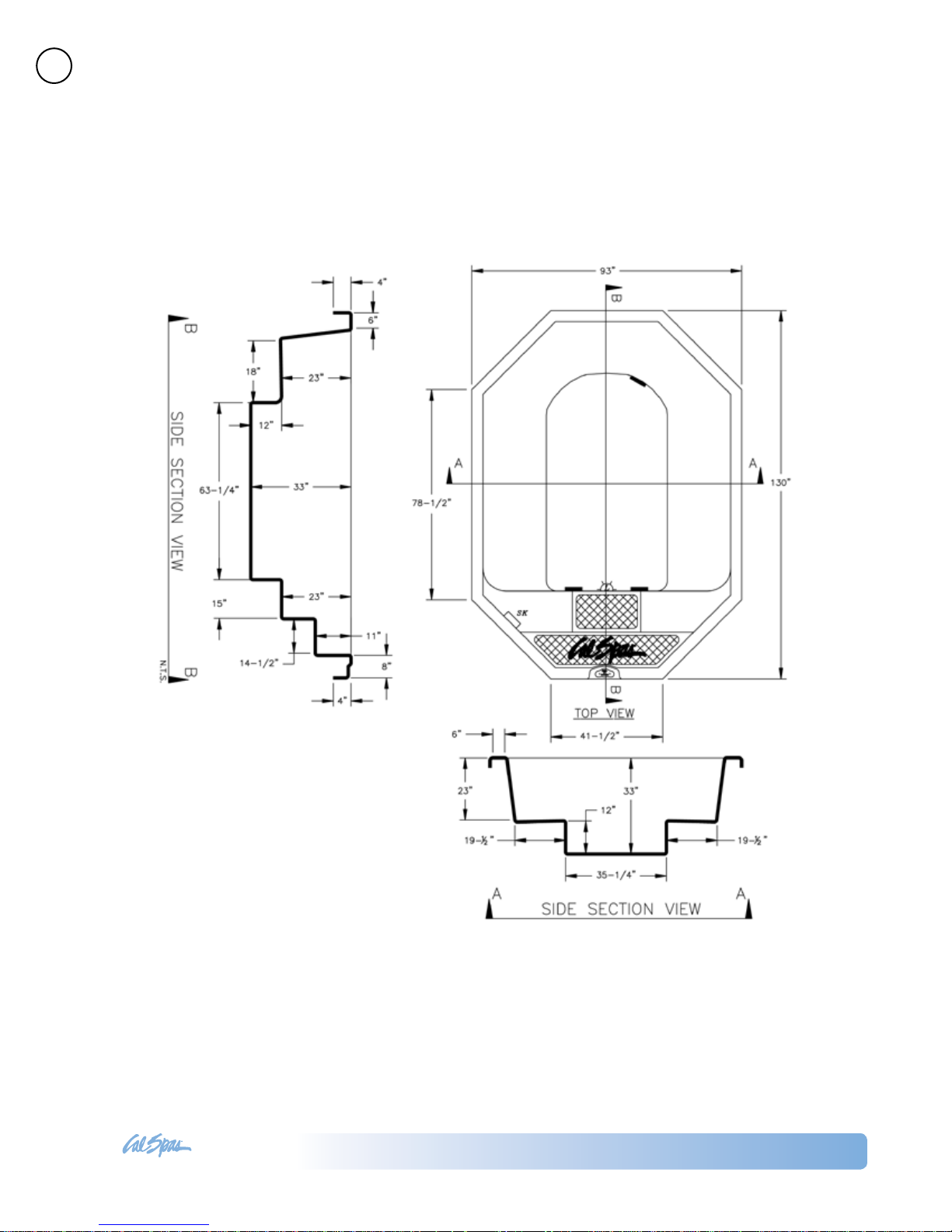
10
IG-405
Preparing for Your New Inground Spa
Inground Spas
LTR20121002, Rev. A
Page 11
www. c al sp a s. co m
IG-406
11
Preparing for Your New Inground Spa
Inground Spas
LTR20121002, Rev. A
Page 12
www. c al sp a s. co m
12
IG-407
Preparing for Your New Inground Spa
Inground Spas
LTR20121002, Rev. A
Page 13
www. c al sp a s. co m
Electrical Requirements – US and Canada
13
Preparing for Your New Inground Spa
All 240V spas must be permanently connected (hard
wired) to the power supply. These instructions de-
scribe the only acceptable electrical wiring procedure.
Spas wired in any other way will void your warranty
and may result in serious injury. See the wiring diagram on page 14.
When installed in the United States, the electrical
wiring of this spa must meet the requirements of National Electric Code, ANSI/NFPA 70-2008 and any applicable local, state, and federal codes. The electrical
circuit must be installed by an electrical contractor
and approved by a local building / electrical inspector.
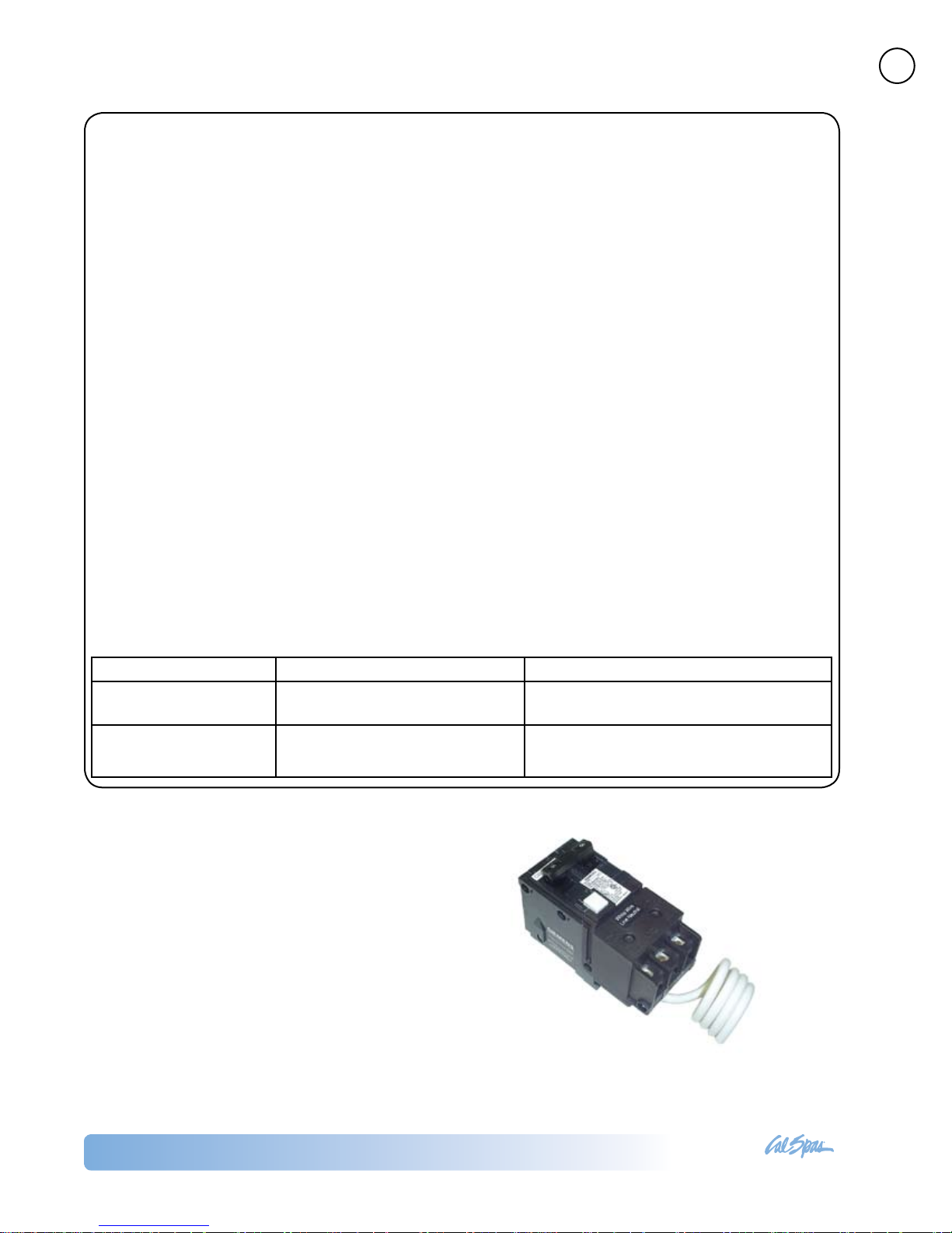
GFCI and Wiring Requirements
The power supplied to the spa must be on a dedicated GFCI protected circuit as required by ANSI/
NFPA 70 with no other appliances or lights sharing
the power.
Use copper wire with THHN insulation. Do not use
aluminum wire.
Use the table below to determine your GFCI and wiring requirements.
Wire runs over 85 feet must increase wire gauge to
the next lower number. For example: A normal 50
amp GFCI with four #8 AWG Copper wires run over
85 feet would require you to go to four #6 AWG copper wires.
Read and follow the heater manufacturer’s safety and
installation instructions prior to installation and operation. Incorrect installation may damage the heater
and void its warranty.
Testing the GFCI Breaker
Test the GFCI breaker prior to rst use and periodically when the spa is powered. To test the GFCI breaker
follow these instructions (spa should be operating):
Press the TEST button on the GFCI. The GFCI will 1.
trip and the spa will shut off.
Reset the GFCI breaker by switching the breaker 2.
to the full OFF position, wait a moment, then turn
the breaker back on. The spa should have power
again.
Spa Model GFCI Required Wires Required
Designer inground spas
with one 5.5 kW heater
Designer inground spa
with two 5.5 kW heaters
One 50 amp GFCI Four #6 AWG copper wires
Service 1: One 50 amp GFCI
Service 2: One 30 amp GFCI
Service 1: Four #6 AWG copper wires
Service 2: Three #8 AWG copper wires
Inground Spas
LTR20121002, Rev. A
Page 14

www. c al sp a s. co m
14
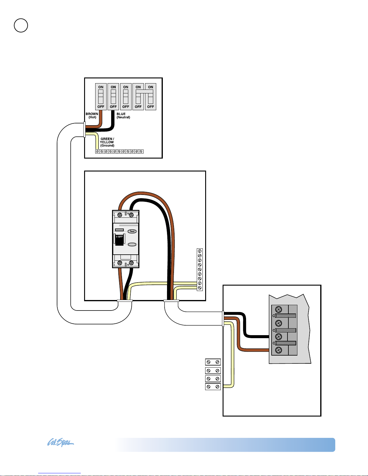
GFCI Wiring Diagram
Preparing for Your New Inground Spa
Inground Spas
LTR20121002, Rev. A
Page 15

www. c al sp a s. co m
Electrical Installation -- Europe
15
Preparing for Your New Inground Spa
All 230V spas must be permanently connected (hard
wired) to the power supply. These instructions de-
scribe the only acceptable electrical wiring procedure.
Spas wired in any other way will void your warranty
and may result in serious injury.
This the only acceptable electrical wiring procedure.
Spas wired in any other way will void your warranty.
See the wiring diagram on page 16.
The electrical wiring of this spa must meet the requirements of any applicable local, state, and federal
codes. The electrical circuit must be installed by an
electrical contractor and approved by a local building
/ electrical inspector.
RCD and Wiring Requirements
The power supplied to the spa must be on a dedicated RCD protected circuit with no other appliances
or lights sharing the power.
Use copper wire with THHN insulation. Do not use
aluminum wire.
Use the table below to determine your GFCI and wiring requirements.
Wire runs over 85 feet must increase wire gauge to
the next lower number. For example: A normal 50
amp RCD with four #8 AWG copper wires run over
85 feet would require you to go to four #6 AWG copper wires.
Testing the RCD Breaker
Test the RCD breaker prior to rst use and periodically when the spa is powered. To test the RCD breaker
follow these instructions (spa should be operating):
Press the TEST button on the RCD. The RCD will 1.
trip and the spa will shut off.
Reset the RCD breaker by switching the breaker 2.
to the full OFF position, wait a moment, then turn
the breaker back on. The spa should have power
again.
Spa Model GFCI Required Wires Required
Designer inground spas with one 3
kW heater
Designer inground spa with one 3
kW heater and one 5.5 kW heater
One 32 amp RCD or two 16 amp
RCDs
Service 1: One 32 amp RCD or
two 16 amp RCDs
Service 2: One 32 amp RCD or
two 16 amp RCDs
Four #10 AWG copper wires
Service 1: Four #10 AWG copper
wires
Service 2: Three #10 AWG copper
wires
Inground Spas
LTR20121002, Rev. A
Page 16
www. c al sp a s. co m
16
GREEN/
YELLOW
(Ground)
GREEN/
YELLOW
(Ground)
GREEN/
YELLOW
(Ground)
CIRCUIT BOARD
RCD Wiring Diagram
Preparing for Your New Inground Spa
Inground Spas
LTR20121002, Rev. A
Page 17

www. c al sp a s. co m
Installing the Inground Shell
17
Preparing for Your New Inground Spa
Inground Spas
LTR20121002, Rev. A
Page 18

www. c al sp a s. co m
18
Equipment Pack Plumbing Connections
Equipment Pack Specications
All Inground spas except IGJ-407:
Equipment pack weight = 250 lbs.
IGJ-407:
Equipment pack weight = 300 lbs.
One 2.5 HP heat pump
One 4 HP swim pump
Note: Equipment pack cannot exceed 15 feet from
spa.
Plumbing Connections
Preparing for Your New Inground Spa
IMPORTANT! Always check local codes prior to any
inground spa installation.
Once the spa and equipment are properly located, you
will want to lay out the plumbing run.
Trenches should be deep and wide enough to allow
all pipes to be buried below the frost line and should
be in as straight a line from the spa to the equipment
as possible. Check local code requirements for underground pipes. Always know what is under the ground
before you dig anywhere.
You will need 2” ex or PVC lines for your suction, intake, and air line. In ground spas have marked intake
and suction lines, making it easy nd and connect to
and from the spa and equipment pack.
The plumbing run should not be any longer than 15
feet to maximize water pressure. Another way to max-
imize water pressure is to limit (or even eliminate) the
use of 90˚ elbows in your plumbing run. A more direct
plumbing run using 45˚ elbows is more efcient, and
promotes increased water pressure.
Identifying Plumbing Lines
The spa’s plumbing lines are clearly marked during
water testing at the factory. This is done to assist installers in properly identifying the installation. We still
recommend that the installers verify plumbing lines
prior to gluing. This can be done by using one of the
following techniques.
Air Test
The air test requires a wet/dry vacuum. Locate the
plumbing line you wish to identify and secure the vacuum hose to cut open end. Turn on the vacuum, enter
the spa and listen for vacuum suction sound from in-
side the spa side lter canister. If you hear the suction
sound in the canister, the line is properly marked and
can be connected to the suction side of the pump on
the equipment pack.
Water Test
The water test requires a garden hose and water
source. Locate the plumbing line you wish to identify
and secure the outlet side of the garden hose to cut
open end. Turn on the water supply to the garden
hose, enter the spa and look for water inside the spa
side lter canister. If you see water in the canister the
line is properly marked and can be connected to the
suction side of the pump on the equipment pack.
If any plumbing line is not properly marked or not
marked at all, follow either the air or water test proce-
dure until all lines are identied prior to gluing.
NOTE: Once complete, water test the plumbing run
for at least three days prior to covering any plumbing
trenches and back-lling spa cavity completely.
NOTE: Some local inspectors require pressure testing the plumbing lines. Although the spa is pressure
tested at the factory, local inspectors may insist on
pressure testing the plumbing run between the spa
and equipment pack.
Inground Spas
LTR20121002, Rev. A
Page 19

www. c al sp a s. co m
19
Gate/Slice Valves
The use of gate valves is recommended on all plumb-
ing lines (both suction and return lines). These valves
are used to contain the spa’s water in either the equipment or the spa. This will assist in the pump priming
process and future servicing without needing to drain
the spa.
NOTE: When draining the spa to perform maintenance, always close the gate valves prior to draining.
This will maintain the pumps prime.
Connecting Plumbing to Remote
Equipment
Connecting the plumbing from the spa to the equipment pack must be performed in accordance to local
and city codes.
NOTE: Most codes require plumbing to be rigid PVC
schedule 40 or heavier in both above and below
ground installations. In most cases, the use of exible
PVC plumbing is acceptable when properly buried in
trenches.
Most water plumbing lines are 2” or larger and must
be schedule 40 or heavier PVC. When plumbing, mini-
mize the use of 90˚ elbows as much as possible. The
use of 45˚ elbows will increase the amount of jet pressure you will have over the use of 90˚ elbows.
The plumbing on the spa shell is labeled by the factory
in the following manner:
Pump 1 Suction: 2” line that connects the spa lter
and bottom drain assembly to the front of pump 1.
Pump 1 Return: 2” line that connects the top of pump
1, through the equipment lter and heater back to
selected jets in the spa.
Pump 2 Suction: 2” line that connects the spa lter
and bottom drain assembly to the front of pump 2.
Pump 2 Return: 2” line that connects the top of pump
2 back to selected jets in the spa.
Ozone Line: 1” line that connects to a 1” exible line
extending off the bottom of the equipment pack lter
canister through an ozone injector (If ozone equipped)
and connected to ozone port on the spa.
Air Blower: 1 1/2” line that is plumbed out of the air
blower (located on the equipment pack) and extended
up 18” above the spas water level to prevent water
ooding the air blower.
Air Venturi: 1/2” line that is plumbed 18” above the
spa’s water level.
Topside Control Panel and Temp Sensor: 1” line that
connects to the bottom of the control box located on
the equipment pack.
Preparing for Your New Inground Spa
Inground Spas
LTR20121002, Rev. A
Page 20

www. c al sp a s. co m
20
Electrical and Electronic Connection
Remote Equipment Topside Control
Panel
The next few steps to complete the installation should
be performed along with installation of the tempera-
ture sensor and 12V spa light wiring (if applicable). All
of these components are generally installed using the
same conduit.
Locate the topside control panel extension loom 1.
in the control box mounted with the equipment
pack. This extension loom and attached black ter-
minal connector (see gure at right) will be used
to connect the topside control panel to the control
box.
Connect one end of the black terminal connector 2.
to the topside control panel cable.
Connect the other end of the terminal connector 3.
to the extension loom.
Preparing for Your New Inground Spa
NOTE: This connection must be kept dry. We recommend that a waterproof junction box be used in installations where moisture could penetrate this terminal
connector.
Lay out the extension loom to verify that you have 4.
enough length to reach the control box. Remember that conduit runs are not generally run in a
straight line. Every bend, and up and down run
consumes line length. Take this into consideration
when verifying electrical and plumbing runs.
Connect the extension loom to the control panel 5.
location on the circuit board located inside the
control box. You will also need to connect both
the temperature and high limit sensors to the cir-
cuit board prior to testing. (See the temperature
and high limit installation instruction on the next
page for proper identication and see the wiring
diagram on the inside cover of the control box for
proper placement.)
Turn on the power supply to the spa equipment 6.
and briey test all functions on the topside control
panel to verify that both connections and extension loom are in working order before proceeding
with the installation.
NOTE: Circuit board programming will not allow spa
operation without both the temperature and high
limit sensors being properly connected to the circuit
board.
Once topside panel operation is veried. Turn off 7.
power, disconnect the extension loom from the
circuit board and GENTLY route through conduit
to complete installation.
NOTE: This loom and its connector are not meant to
withstand heavy pulling. Make sure, when routing the
extension loom and temperature sensor lines through
conduit, you exercise extreme caution.
Once properly run through the conduit, repeat steps
5 and 6 above.
Inground Spas
LTR20121002, Rev. A
Page 21

www. c al sp a s. co m
21
Inground Spa Light Installation Instructions
On spas ordered with inground lights, the factory
installs the light niche for you. The next steps of
installation should be performed by a qualied licensed
electrician.
Always read and follow light manufacturer’s safety
and installation instructions prior to installation and
operation. Incorrect installation may damage the light
and void its warranty.
The light circuit must be on a GFCI protected service
(alone or with a switch).
The water resistant junction box (or for 12 volt models,
the low voltage transformer) must be located:
at least 8” (20 cm) above water level•
at least 4” (10 cm) above ground level, and•
at least 48” (121 cm) away from the spa.•
See gure below.
Light niche and any metallic items in a 5’ (152 cm)
radius must be properly bonded with #8 AWG
grounding wire.
Connect rigid conduit to the 3/4” hub located at 1.
the back of the light niche and run to a water re-
sistant junction box (or for 12 volt models to a low
voltage transformer) no further than 25’ (7.6m).
Remember this is a water cooled light, so the conduit and all connections must be leakproof.
Feed the light cord through the rigid conduit to 2.
the junction box, leaving at least 4 feet of cord at
the end of the light xture. This slack in the light
cord will allow servicing without draining the spa
in the future.
Wrap light cord slack around back of light housing 3.
and attach light to niche with mounting screw.
Cut the cord at the junction box, leaving at least 4.
6” (15 cm) of cord to make connections.
Strip 6” (15 cm) of the out cord jacket to expose 5.
the three insulated wires. Be careful not to damage the insulation on the three inner wires.
Connect the three wires to the corresponding cir-6.
cuit wires in the junction box and secure the junction box cover in place.
Replace the light assembly in the niche and tight-7.
en the special pilot screw.
Fill the spa until the underwater light is completely 8.
submerged in water before operating the light for
more than 10 seconds. Turn on the main switch or
circuit breaker, as well as the spa light control, to
check for proper operation
Important: Make sure spa light is submerged in
at least 18” of water prior to testing.
Preparing for Your New Inground Spa
Inground Spas
LTR20121002, Rev. A
Page 22

www. c al sp a s. co m
22
Preparing for Your New Inground Spa
Inground Spas
LTR20121002, Rev. A
Page 23

www. c al sp a s. co m
Pouring the Deck
23
Preparing for Your New Inground Spa
It is recommended that all electrical hook ups and all
plumbing be completed before pouring the concrete.
Make certain all electrical inspections on lights, bonding and all other electrical work have been completed
and checked off by the local inspectors prior to pro-
ceeding with your concrete or nish work. It is a good
idea to run the spa for at least 24 hours before pouring
the concrete to insure there are no leaks. We understand you want to enjoy your spa now, but a 24 hour
period with your spa running will let you know of any
problems before they will be extremely hard to x.
The type of decking you have selected will have determined the grade of the spa. If you are pouring a
regular deck up to the spas coping, then the top of
the coping should be 4” above the surrounding area.
In either event, it is recommended to dig out an area
around the spa exposing the ange of the coping and
just under it. This is important, as concrete should be
packed under and over the ange of the spa, as the
deck is poured. This will lock the spa into the concrete
and provide for a much stronger bond of the spa to
the deck. It will also eliminate cracking of the deck
where it meets the spa.
When setting your outside forms, remember you want
any water from rain or splash out to run off the deck,
not into the spa. If your deck is going to tie into an existing deck, then some type of drain system should be
planned to handle the run off. Proper drainage planning is very important.
An experienced concrete nisher should always be
used when pouring spa decks, especially when you
are doing a cantilevered deck, as the forms must be
taken off at the proper time to allow nishing of the
inside of the form.
Inground Spas
LTR20121002, Rev. A
Page 24

www. c al sp a s. co m
24
9800 Electronic Control Operation
Initial Start-up
When rst powered up, your spa will perform a self-diagnostic check and then automatically go into priming
mode. The topside will display PR to indicate this. Priming mode will be active for less than ve minutes. When
the spa has nished priming, the heater will be activated and the water temperature will be maintained in standard mode. The spa will automatically heat to 100°F (37.5°C) at start-up until you change the set temperature
as listed in the “Temperature Adjustment” section below.
These instructions will describe features and options
that your particular spa may not be equipped with.
Temperature Adjustment
Operating Your Spa
80°F - 104°F (26.0°C - 40.0°C)
The start-up temperature is set at
100°F (37.5°C). The last measured
temperature is constantly displayed
on the control panel. Note that the last
measured spa temperature is displayed.
The displayed temperature will be updated
when the pump has been running for at least two
minutes.
Press the “UP” or “DOWN” buttons once to display the
set temperature. Each time either button is pressed
again, the set temperature will increase or decrease
depending on which button is pressed. After three
seconds, the control panel will automatically display
the last measured spa temperature.
Time
When time hasn’t been programmed, the “TIME” icon
ashes. To set the time, press the “TIME” button and
then the “MODE/PROG” button. Use the “UP” and
“DOWN” buttons to adjust time. See the next page
for more detailed instructions.
Standard, Economy, Sleep, and Standby
Modes
Mode/Prog: This button is used to switch between
standard, economy, and sleep modes.
Press “MODE/PROG” to enter mode program-1.
ming.
Press the “DOWN” button to cycle through to the 2.
desired mode.
Press “MODE/PROG” to conrm selection.3.
Standard Mode: This is programmed to maintain
the desired temperature. Note that the last measured
spa temperature displayed is current only when the
pump has been running for at least two minutes. The
“STAND” icon will display until the mode is changed.
Economy Mode: Economy mode heats the spa to the
set temperature only during lter cycles. The “ECON”
icon will display until the mode is changed. Pressing
the “JETS 1” button while in economy mode puts the
spa in standard-in-economy mode, which operates the
same as standard mode but reverts back to economy
mode automatically after one hour. During this time,
pressing the “MODE/PROG” button will revert to economy mode immediately.
Sleep Mode: Sleep mode heats the spa to within
20°F (6.7°C) of the set temperature only during lter
cycles. The “SLEEP” icon will display until the mode is
changed.
Standby Mode: Pressing “Warm” or “Cool” then
“JETS 2” will turn off all spa functions temporarily. This
is helpful when changing a lter. Pressing any button
resets the spa.
Jets 1 and Jets 2
Press the “JETS 1” button once to turn pump 1 on
or off and to shift between low and high speeds if
equipped. If left running, the low speed turns off af-
ter two hours and the high speed turns off after 15
minutes. On non-circulation systems, the low speed of
pump 1 runs when the blower or any other pump is
on. It may also activate for at least two minutes every
30 minutes to detect the spa temperature and then
to heat to the set temperature if needed, depending
upon the mode. When the low speed turns on automatically, it cannot be deactivated from the panel;
however, the high speed may be started.
Option
This is an optional feature. Press the “OPTION” button to turn the optional equipment on and off. If left
Inground Spas
LTR20121002, Rev. A
Page 25

www. c al sp a s. co m
25
on, the equipment will automatically turn off after 15
minutes.
Light
Press the “LIGHT” button to turn the spa light on and
off and to shift between dim and bright settings if your
light is dimmable. On dim, the control panel will show
the center circle plus one quarter of the light beams.
Half of the light beams will show on medium brightness, and all of the light beams will show on bright.
Invert
Press the “INVERT” button to change the numbers
in the display to read upside down. Another press
returns the display to the right-side-up position. This
enables you to read the display while you are in the
spa.
Locking the Panel
To lock the panel:
Press “TIME”, “JETS 1”, and the “UP” button within •
three seconds. When locked, the panel will display
“LOCK”. All buttons are frozen except the “TIME”
button.
To unlock the panel:
Press “TIME”, “JETS 1” then the “DOWN” button •
within three seconds.
Setting the Temperature Lock
To activate the temperature lock:
Press the “UP” or “DOWN” button, “TIME”, “JETS •
1”, then the “UP” button within three seconds. The
panel will display “TEMP LOCK” when the set temperature is locked.
To unlock the set temperature:
Press the “UP” or “DOWN” button, “TIME”, “JETS •
1”, and then the “DOWN” button.
Circulation Pump
This is an optional feature. The circulation pump will
come on when the system is checking temperature,
during lter cycles, during freeze conditions, or when
another pump is on.
Preset Filter Cycles
There are two lter cycles per day. The start and end
times of each cycle are programmable. To program,
set the time as instructed above, then press “MODE/
PROG” to advance to the next setting (or to exit after
the last setting). The default lter cycles are as fol-
lows:
The rst lter cycle is automatically activated at •
8:00 AM and operates the pump until 10:00 AM.
The “FILTER 1” indicator icon will light when lter
1 is running.
The second lter cycle is automatically activated •
at 8:00 PM and operates the pump until 10:00 PM.
The “FILTER 2” indicator icon will light when lter
2 is running.
The pump and the ozone generator will run during ltration. At the start of each lter cycle, the blower will
run on highest speed for 30 seconds to clean out the
air channels. The lowest speed of pump 2 and pump
3 will run for ve minutes. In the event of power loss
or shut down, the time of day will need to be reset for
lter cycles to run according to your desired programming.
Clean-up Cycle
When the pump or blower is turned on by a button
press, a clean-up cycle begins 30 minutes after the
pump or blower is turned off or times out. The pump
and the ozone generator will run for one hour.
Ozone
This is an optional feature. On most systems, the
ozone generator (if installed) runs during lter cycles
(except when pump 1 is operating at high speed on a
non-circ system) and during clean-up cycles. On some
systems, the ozone generator operates whenever the
pump runs. If your system is congured with the optional ozone disable feature, the ozone generator will
turn off for one hour any time a function button (“JETS
1”, “JETS 2”, “OPTION” etc.) is pressed.
Freeze Protection
If the temperature sensors detect a drop to 44°F
within the heater, the pump automatically activates
to provide freeze protection. The equipment stays
on until four minutes after the sensors detect that
the spa temperature has risen to 45°F or higher. In
colder climates, an optional additional freeze sensor
may be added to protect against freeze conditions that
may not be sensed by the standard sensors. Auxiliary
freeze sensor protection acts similarly except with the
temperature thresholds determined by the switch and
without a four-minute delay in turnoff.
Operating Your Spa
Inground Spas
LTR20121002, Rev. A
Page 26

www. c al sp a s. co m
26
Operating Your Spa
Periodic Reminder Messages
Press the “Mode” button to reset a displayed reminder.
Message Frequency Action Required
rPH
rSA
rCL
rtg
rdr
rCO
rCH
Your new Cal Spa comes equipped with an electric heater. Following the directions listed below will ensure
the most efcient operation:
Every 7 days Test and adjust chemical levels per manufacturer’s instructions.
Every 7 days Test and adjust chemical levels per manufacturer’s instructions.
Every 30 days Remove, clean, and reinstall lter per manufacturer’s instructions.
Every 30 days Test and reset GFCI per manufacturer’s instructions. Drain and rell
spa per manufacturer’s instructions.
Every 90 days Drain and rell spa per manufacturer’s instructions.
Every 180 days Clean and condition spa cover
Every 365 days Install New Bio-Clean™ Filter
NOTE: This method is only for spa usage under two hours a week.
Keep the spa’s operating temperature 5˚ F below the desired usage temperature when not in use. One •
or two hours before use, set the temperature to the desired temperature.
If the spa usage exceeds two hours a week, the set temperature should remain at the desired usage •
temperature.
The air venturis should be used sparingly. When open, water temperature drops quite rapidly and can •
also dissipate chemicals.
Allowing the water temperature to lower more than 10˚F below the desired usage temperature and reheating
it prior to usage will cause the heater to operate longer than it normally would maintaining the desired temperature. Doing this will increase your operating cost and makes your heater work more than necessary.
Inground Spas
LTR20121002, Rev. A
Page 27

www. c al sp a s. co m
Diagnostic Messages
Message Meaning Action Required
No message
on display
BUF Internal problem detected. Repair required. Contact your dealer or service organi-
dr Insufcient water detected in
dry
dY
Ec Indicates heater is in Economy
--F or --C Temperature unknown After the pump has been running for two minutes, the
HL
HFL
IC
ICE
LF Persistent low ow problems.
OH
OHS
1) Spa temperature is unknown. 1) After pump has been running for 2 minutes temperature will be displayed.
2) Spa is in Economy or Sleep
mode.
3) Power has been cut off to the
spa.
heater. Spa will be shut down for
15 minutes.
Insufcient water detected in
heater. Spa is shut down.
(Displays on third occurrence of
dr message.)
Mode.
A difference in readings between
temperature sensors has been
detected indicating a possible
water ow problem.
Potential freeze condition detected.
Heater is shut down, but other
spa functions continue to run
normally. Displays on the fth
occurrence of the HL or HFL message within 24 hours.
Overheat protection. The spa has
shut down. One of the sensors
has detected that the spa water
is 110°F.
2) In Economy or Sleep mode, the pump may be off for
hours outside a lter cycle. If you wish to see the cur-
rent spa temperature, either switch to Standard mode
or turn Jets1 on for at least two minutes.
3) The control panel will be disabled until power returns. Spa settings and time of day will be preserved for
30 days with a battery back-up.
zation.
Check water level in spa. Rell if necessary. Make sure
pumps are been primed and lter cartridges are clean.
Press any button to reset or wait 15 minutes and spa
will automatically reset. If message spa does not reset,
call your dealer or service organization.
Follow directions for dr message and press any button
to reset spa. Spa will not automatically reset when dry
or dY is displayed.
None.
temperature will be displayed.
Make sure spa is lled to proper level and that pumps
are primed and lter cartridges are clean. If message
does not reset, call your dealer or service organization.
No action required. The pumps and the blower will automatically activate regardless of spa status.
Follow action required for HL or HFL message. Heating
capacity of the spa will not reset automatically. Press
any button to reset.
DO NOT ENTER THE WATER. Remove the spa cover and
allow water to cool. At 107°F, the spa should automatically reset. If spa does not reset, shut off the power to
the spa and call your dealer or service organization.
27
Operating Your Spa
Inground Spas
LTR20121002, Rev. A
Page 28

www. c al sp a s. co m
28
Operating Your Spa
Message Meaning Action Required
HH
OHH
Overheat protection (spa is shutdown). One sensor has detected
118˚F (48˚C) at the heater.
DO NOT ENTER THE WATER!
Remove the spa cover and allow spa to cool below
107˚F (42˚C). Press any button on the topside display
to reset spa. If spa will not reset after spa has cooled,
turn off power for approximately 30 seconds and then
turn power back on. If display message is repeated then
shut the power off to the spa and call your dealer or
service organization.
Pr When your spa is rst actuated, it
will go into priming mode.
The priming mode will last for up to four minutes and
then the spa will begin to heat and maintain the water
temperature in the Standard mode.
SF Safety Suction. Spa is shut down. The display will show SF when a vacuum switch closes.
All functions will turn off and the system will be disabled
until a panel button is pressed.
SL Indicates heater is in Sleep Mode. None.
SA
Sb
SNA
Spa is shut down. The sensor
that is plugged into the sensor
“A” or “B” jack is not working.
If the problem persists, contact your dealer or service
organization. (May appear temporarily in an overheat
situation and disappear when the heater cools.)
Snb
Sns
Sn
Sensors are out of balance.
If this is alternating with the •
Contact your dealer or service organization.
temperature, it may just be a
temporary condition.
If the display shows only this •
message (periodically blinking), the spa is shut down.
ST Indicates heater is in Standard
Mode.
Stby Pressing a button combination
on the user panel has activated
Standby Mode.
None.
Press any button to leave Standby Mode and return to
normal operation.
Inground Spas
LTR20121002, Rev. A
Page 29

www. c al sp a s. co m
Adjustable Jets
29
Operating Your Spa
Diverter Knobs
Almost all of the jets in your spa are adjustable.
Rotating the face of an adjustable jet to the left
(counter-clockwise) will decrease the amount of
water ow through the jet. Rotating the face of an
adjustable jet to the right (clockwise) will increase
the amount of water ow through the jet.
Neck jets adjust in the opposite directions (counterclockwise to increase, clockwise to decrease).
Diverter knobs are 1” and 2” knobs located around
the top of your spa. They allow you to divert water
through jets from one side of the spa to the other, or
in most cases from oor jets to wall jets. This is accomplished by rotating the diverter knob to the left
(counterclockwise), decreas-
ing the amount
of water ow
through a section of jets. To
increase the
amount of water
ow through the
other section
of jets, rotate
the handle to
the right (clockwise).
Inground Spas
LTR20121002, Rev. A
Page 30

www. c al sp a s. co m
30
Filtration
Ing et augait alit esto dolut dio doleniam quat am vel etue
vendiam quis duip ea ating et utem quam, sendit, velesequisit am dunt niscil ilit alit nonumsan utatin utat num voloreril
in ut pratie dionull umsandio consed dolumsandit at. Rat,
consequi tinim ilisi bla feuis euguerc ilisi.
Em verit iliqui endiam nulluptat lamcore minibh elestio numsandip eraesectem diatio ercing ea cortis delissed dunt
utpatisi.
Ut vel ut wis atis nonullut augiam augait lore dolore erci te ea
consequat.
Met prate er sit dolor iriureetuer si.
Feummy nullamcore magna ad dio er
sequamconum nis eu feugiamet, vent
et wisis ero dolore dip exeraestie estie
vel inisci elisl ut diat, cons aut alit lut
lore tin hent adiam iustrud molor
sustis essit wiscilit wisi.
Regularity
Ing et augait alit esto dolut dio doleniam quat am vel etue
vendiam quis duip ea ating et utem quam, sendit, velesequisit am dunt niscil ilit alit nonumsan utatin utat num voloreril
in ut pratie dionull umsandio consed dolumsandit at. Rat,
consequi tinim ilisi bla feuis euguerc ilisi.
Em verit iliqui endiam nulluptat lamcore minibh elestio numsandip eraesectem diatio ercing ea cortis delissed dunt
utpatisi.
Ut vel ut wis atis nonullut augiam augait lore dolore erci te ea
consequat.
Met prate er sit dolor iriureetuer si.
Feummy nullamcore magna ad dio er
sequamconum nis eu feugiamet, vent
et wisis ero dolore dip exeraestie estie
vel inisci elisl ut diat, cons aut alit lut
lore tin hent adiam iustrud molor
sustis essit wiscilit wisi.
Sanitation
Ing et augait alit esto dolut dio doleniam quat am vel etue vendiam quis
duip ea ating et utem quam, sendit,
velesequisit am dunt niscil ilit alit nonumsan utatin utat num voloreril in ut
pratie dionull umsandio consed
dolumsandit at. Rat, consequi tinim ilisi bla feuis euguerc ilisi.
Em verit iliqui endiam nulluptat lamcore minibh elestio numsandip eraesectem diatio ercing ea cortis delissed dunt
utpatisi.
Ut vel ut wis atis nonullut augiam augait lore dolore erci te ea
consequat.
Met prate er sit dolor iriureetuer si. Feummy nullamcore
magna ad dio er sequamconum nis eu feugiamet, vent et
wisis ero dolore dip exeraestie estie vel inisci elisl ut diat, cons
aut alit lut lore tin hent adiam iustrud molor sustis essit wiscilit wisi.
Chemical Balance
Ing et augait alit esto dolut dio doleniam quat am vel etue vendiam quis
duip ea ating et utem quam, sendit,
velesequisit am dunt niscil ilit alit nonumsan utatin utat num voloreril in ut
pratie dionull umsandio consed
dolumsandit at. Rat, consequi tinim
ilisi bla feuis euguerc ilisi.
Em verit iliqui endiam nulluptat lamcore minibh elestio numsandip eraesectem diatio ercing ea cortis delissed dunt
utpatisi.
Ut vel ut wis atis nonullut augiam augait lore dolore erci te ea
consequat.
Met prate er sit dolor iriureetuer si. Feummy nullamcore
magna ad dio er sequamconum nis eu feugiamet, vent et
wisis ero dolore dip exeraestie estie vel inisci elisl ut diat, cons
aut alit lut lore tin hent adiam iustrud molor sustis essit wiscilit wisi.
F
i
l
t
r
a
t
i
o
n
R
e
g
u
l
a
r
i
t
y
C
h
e
m
i
c
a
l
B
a
l
a
n
c
e
S
a
n
i
t
a
t
i
o
n
Your Key
To Clear
Water
Clear Water Plan
This section is intended for new spa owners with
no experience with water chemistry. Everyone’s experience with maintaining water quality is different,
but there are some general concepts you need to
know.
Water maintenance is not difcult, although it requires regular attention. The most important thing
to understand about taking care of your spa water is
that preventive action is much easier than correcting
Clear Water Plan
water quality issues.
The Key to Clear Water
Excellent water quality is a simple matter of four things:
Regularity
Clear water requires regular maintenance.
Establish a routine based on a regular
schedule for your spa water maintenance.
Maintaining your water quality helps the en-
joyment of your spa and extends your spa’s
life by preventing damage from neglect and
chemical abuse.
See page 35 for the schedule of recommended maintenance.
Sanitation
Sanitizers kill bacteria and
viruses and keep the water
clean. A low sanitizer level
will allow microbes to grow
quickly in the spa water.
We recommend using either chlorine or bromine as your sanitizer.
See page 32 for learn how to use sanitizer.
Contents of this section:
Testing and Adjusting Spa Water
Sanitation
Filtration
Bather Load
Starting the Spa with Fresh Water
Maintenance Schedule
Troubleshooting Water Clarity Problems
Cleaning your lter regularly is the easiest
and most effective single thing you can do
to keep your water clear.
A clogged or dirty lter will cause the heater
and pump to work harder than they need
to, possibly causing them to fail.
The spa’s heating system will only function
with the proper amount
of water ow through the
system.
See page 33 for lter clean-
ing instructions.
You will need to test and
adjust the chemical balance of your spa water. Al-
though this is not difcult,
it needs to be done regularly.
Depending on your choice of sanitizer, you
need to test the level of calcium hardness,
total alkalinity, and pH.
See page 32 for learn how to balance your
spa water.
Filtration
Chemical Balance
Inground Spas
LTR20121002, Rev. A
Page 31

www. c al sp a s. co m
Testing and Adjusting Spa Water
8.2
8.0
7.8
7.6
7.4
7.2
7.0
6.8
6.6
Too alkaline,
causes scaling
Ideal balance
Too acidic,
causes corrosion
Need to lower the pH level
Need to raise the pH level
You have two types of testing methods to choose from:
The • reagent test kit is a method which provides a high level of accuracy. It is available in either liquid
or tablet form.
Test strips • are a convenient testing method commonly used by spa owners.
31
Clear Water Plan
Balancing the Total Alkalinity
Total alkalinity (TA) is the measure of the total levels of carbonates, bicarbonates, hydroxides, and
other alkaline substances in the water. TA can be
considered a “pH buffer”. It is the measure of the
ability of the water to resist changes in pH level.
The recommended total alkalinity is 80 - 120
ppm.
If the TA is too low, the pH level will uctuate wide-
ly from high to low. Low TA can be corrected by
adding a pH-alkalinity increaser.
If the TA is too high, the pH level will tend to be
too high and may be difcult to bring down. High
TA can be corrected by adding a pH-alkalinity decreaser.
When the TA is balanced, it normally remains stable, although adding water with high or low alkalinity will raise or lower the TA level.
Balancing the pH
The pH level is the measure of the balance between
acidity and alkalinity.
Balancing the Calcium Hardness
Calcium hardness (CH) is a measure of the total
amount of dissolved calcium in the water. Calcium
helps control the corrosive nature of the spa’s water and is why soft water is not recommended. The
low calcium content of soft water is very corrosive
to the equipment and can cause staining of the spa
shell.
The recommended calcium hardness is 150
- 200 ppm.
If the CH is too low, add a calcium hardness increaser.
If the CH is too high, dilute the spa water with soft
water.
When the CH is balanced, it normally remains stable, although adding soft water or very hard water
will raise or lower the CH level.
If the pH is too low, it can cause corrosion of metal xtures and the heating element. Low pH can be corrected
by adding a pH-alkalinity increaser.
If the pH is too high, it can cause scaling by allowing
metals or minerals to form deposits and stain spa surfaces. High pH can be corrected by adding a pH-alkalinity decreaser.
Testing For: Ideal Range (ppm)
Total Alkalinity 80 120
Calcium Hardness 150 200
pH 7.4 7.6
Inground Spas
LTR20121002, Rev. A
Minimum Maximum
Page 32
www. c al sp a s. co m
32
Sanitation
After you ll your spa, you need to decide which chemical sanitizer you wish to use. Consult your Cal Spas
dealer for the right decision with regards to your lifestyle and spa usage.
We recommend either bromine or chlorine as your sanitizer. Both work well when maintained regularly.
Sanitizers kill bacteria and other organic waste by breaking them down to non-harmful levels and are ltered
Clear Water Plan
out.
Make sure you follow all instructions.
Whichever plan you decide on, follow it completely and don’t take shortcuts. It will provide you with clean,
safe, clear spa water with a minimum of effort.
DO NOT use trichlor. Trichlor is very acidic and the hot temperature of the spa causes it to
dissolve too quickly. It will cause damage to your spa and will void your warranty.
Using Chlorine as a Sanitizer
If you choose to use chlorine as a sanitizer, only
use granulated chlorine, not liquid chlorine.
Once a week, check the chlorine level using either
a test strip or a reagent kit. See the table on the
following page for the ideal range.
Add one or two tablespoons of granulated chlorine
to the spa water weekly. Note that chlorine dissipation rate will be faster at higher water temperatures and slower at lower temperatures.
When you add chlorine, open all of the jets and run
the spa at high speed with the cover open for at
least 30 minutes.
Follow the maintenance schedule on page 35.
Testing For: Ideal Range
Chlorine level
Without ozonator
Using Bromine as a Sanitizer
Bromine is a very effective sanitizer that produces
low chemical odors. Unlike chlorine, it can break
down bacteria and other impurities to a safe level
with a low burn-out rate.
Bromine is available in both granulated and tablet form. Use granulated bromine to establish your
bromine base. Use tablets to maintain it.
When you begin with fresh water, add 2 ounces of
granulated bromide. Open all of the jets and run
the spa at high speed. This is your base bromine
level as the tablets will take a while to dissolve.
Place three or four bromine tablets in the chamber
inside the oater.
Follow the maintenance schedule on page 35.
(ppm)
Minimum Maximum
3.0 5.0
With ozonator
Bromine level
Without ozonator
With ozonator
2.0 4.0
6.7 11.0
5.7 10.0
Inground Spas
LTR20121002, Rev. A
Page 33
www. c al sp a s. co m
Shocking the Water
In addition to using a chemical sanitizer, you will periodically need to shock the water. Shocking the water
helps remove burned-out chemicals, bacteria, and other organic material from your spa’s water and improves your sanitizer’s effectiveness.
Do not use chlorinating shock, which will damage your spa’s jets and pump seals. Only use an oxidizer shock.
It can be used with either chlorine or bromine sanitizers.
Add one ounce of oxidizer shock once a week, after heavy bather loads, or if the water has a strong odor.
Spa must be running with all of the jets on high for 30 minutes with the cover open. If necessary, repeat
oxidizer shock in 30 minute intervals.
Chemical Safety
Read and follow all printed instructions listed on bottles, packages. Failure to follow
chemical directions may result in serious injury, sickness, or even death.
33
Clear Water Plan
Do not exceed chemical dosages as recommended
in the Clear Water Plan or on chemical bottles and
packages.
Never change chemical brands or types without com-
pletely draining, ushing and thoroughly cleaning the
spa and cover rst.
Never mix chemicals together.
Do not allow chemicals to come in contact with skin,
eyes or clothing. Remove and wash clothing that
Filter Cleaning
The lter is the part of your spa that removes the
debris from the water and needs to be cleaned on a
regular basis to maximize your spa’s ltering performance and heating efciency.
In addition to spraying off the lter weekly to remove
surface debris, your lter should be deep cleaned
periodically to dissolve scale and particles that get
lodged deep within the lter bers and impede the
ltration process. Even if the lter looks clean, scale
and particles can clog the bers and prevent water
from owing through the lter resulting in the most
common spa problem—no heat, caused by a dirty
lter.
We recommend you clean your lter once a month
and replace it once a year or as necessary.
Remove the lter by turning it counterclockwise, 1.
unscrewing the bottom threads, then pulling it
up and out.
may have been exposed to chemical contact prior to
wearing them again.
Inhaling or ingesting chemicals will cause serious injury, sickness, or even death.
Chemicals must be stored completely out of the
reach of children in an area that is well vented, cool,
and dry. Failure to provide a proper area for chemical
storage may result in serious injury, sickness, re explosion and even death. Do not store your chemicals
inside the equipment area of your spa.
Place the dirty lter into a bucket of water deep 2.
enough to cover the lter. Add 8 oz of liquid lter
cleaner to the bucket of water.
Note: It is a good idea to keep a spare lter to
use in the spa while the dirty lter is being deep
cleaned. This way, you can rotate the lters and
both will last longer.
Twist off the tablet tube and set it aside3.
Soak the lter for a minimum of 24 hours.4.
Spray the lter with a water hose. Spray each 5.
pleat carefully.
Put fresh bromine in the tablet tube (if you use 6.
it as a sanitizer) and twist it back on top of the
lter.
Reinstall the lter. Do not overtighten.7.
Inground Spas
LTR20121002, Rev. A
Page 34

www. c al sp a s. co m
34
Bather Load
“Bather Load” is the term used to describe the number of people using a spa, combined with the length
of usage, and the frequency of usage. All these factors have a great effect on the spa water. The higher
the bather load, the more chemicals need to be add-
ed and a longer ltration time will be needed.
Clear Water Plan
All versions of the Cal Spas Clear Water Plan are
designed for spas with average bather load (3 to
Starting the Spa with Fresh Water
Prior to lling a spa for the rst time, or after a routine draining, you will want to follow this start-up
plan to extend water life and performance.
As with all chemical dosages listed in these Clear
Water Plans, start-up dosages are intended for 500-
gallon spas. Please adjust the chemical dosages to
the capacity of your particular spa.
Clean the surface of the spa with a multi-purpose 1.
cleaner.
4 people, 15 minutes of usage, three times a week
at 100 degrees) If your bather load exceeds these
guidelines, and you experience water quality prob-
lems, increase the amount of ltration rst, (go to the
next higher ltration number) then if water quality
is still not adequate, consult the advice of your Cal
Spas dealer for additional chemical or system recommendations. Be sure to give them your bather load
information.
Adjust total alkalinity (acceptable range is •
80-120ppm).
Adjust pH if necessary (between 7.2 to 7.8).•
Add either chlorine or bromine (but not both).5.
Chlorine: Add two tablespoons of granulated chlo-
rine to the spa water.
Bromine: Add 2 oz of granulated bromine to estab-
lish a bromine base.
Apply a protective coat of surface protectant to 2.
the acrylic surface.
Fill the spa to the proper water level with normal 3.
tap water. (Do not use soft water.)
Use test strip and balance the spa water.4.
Water level is very important to the operation of your spa. If the water level is too low or too high, your spa will not operate properly. The water level
should be about six inches from the top when the spa is not being used.
Add 2 bromine tablets to bromine oat-
er.
Turn on jets for 15 minutes. Leave spa uncov-6.
ered during this time.
Put cover on spa and allow to heat up to desired 7.
temperature.
Inground Spas
LTR20121002, Rev. A
Page 35

www. c al sp a s. co m
Maintenance Schedule
35
Clear Water Plan
Each time you rell the spa
Prior to each use Test the spa water using either test strips a reagent test kit. Adjust
Once a week Test the spa water using either test strips a reagent test kit. Adjust
Once a month Deep clean your spa’s lter. (Follow lter cleaning instruction at
Every two to four months Drain and clean your spa with multi-purpose cleaner.
Once a year
Follow the section “Starting the Spa with Fresh Water”.
chemical levels as necessary.
chemical levels as necessary.
beginning of Clear Water Plan)
Polish the acrylic surface with a surface protectant.
Clean and treat spa cover, pillows, and Cal Select cabinet (if
equipped).
Rell your spa, following the section “Starting the Spa with Fresh
Water”.
Replace lter cartridges if the pleats appear frayed.
We recommend that your spa water be changed every 4 to 6 months. You may nd the need to change your
spa water more frequently with heavy use. When empty, your spa should be cleaned with a non-abrasive allsurface cleaner, and then rinsed thoroughly.
Inground Spas
LTR20121002, Rev. A
Page 36

www. c al sp a s. co m
36
Cleaning and Maintenance
Removing and Reseating the Pillows
You can remove the pillows for cleaning and maintenance quickly and easily. This method works for all types
of pillows.
Grab the lower edge of the pillow with both hands rmly and pull up. As you do this, the pillow inserts will
pop out of the holes.
Cleaning and Maintenance
Reseat the pillows by aligning the pillow inserts with the holes and striking the pillow hard enough to insert
the pegs back into the holes.
Spa Cover
Important! Keep the spa covered when not in use!
Covered spas will use less electricity in maintain-•
ing your set temperature.
Covering your spa will protect your spa’s nish •
from the sun’s ultraviolet rays.
You are required to keep the spa covered to •
maintain warranty coverage.
Covering your spa helps prevent children from •
drowning in the spa.
See the manual enclosed with your cover for instructions on mounting the locks and how to lock and unlock the cover.
In addition, while the spa cover is rigid, it is not designed to support any weight. Therefore, as a safety
precaution and to preserve the life of your cover, you
must not sit, stand, or lie on it; nor should you place
objects of any kind on top of it.
Inground Spas
LTR20121002, Rev. A
Page 37

www. c al sp a s. co m
Draining Your Spa
Your spa should be drained every four to six months, and relled with fresh tap water. The following is the
recommended method for draining your spa.
Turn off the power at the breaker.1.
Remove all lters.2.
Hook up the female end of a garden hose to the drain tting (if equipped).3.
Place the other end of the garden hose where you would like the water to drain to.4.
Let spa drain completely, then remove garden hose and rell.5.
Cleaning and Replacing the Filter
Filtration is one of the most important steps you can take to ensure clean, clear water. It is far less expensive
to x water clarity problems by ltering your spa than by using excessive amounts of chemicals, excessive
ltration times, or by water replacement.
See the section “Clear Water Plan” for more information on cleaning your lter.
37
Cleaning and Maintenance
Winterizing (Cold Climate Draining)
In many areas of the country, the temperature drops below 32˚F (0°C). We recommend that you always
have your spa full of water and running at normal spa temperatures (80˚F to 100˚F, 26.7°C to 37.8°C). This
will help reduce the risk of freezing in your spa and your spa’s equipment.
WARNING: If you nd the need to drain your spa, please be aware of the potential of freezing in your spas
equipment and plumbing. Even if the directions below are followed perfectly, there is no guarantee that your
spa will not suffer freeze damage and thereby void the warranty coverage.
Open all lter covers.1.
Remove the lter baskets and lters.2.
Drain your spa completely as described in the instructions above.3.
Remove drain plugs from the front of the pumps.4.
Disconnect the unions from both sides of the pump.5.
Use a wet/dry vacuum to blow any remaining water out of the jets and equipment area.6.
Cover your spa with a good spa cover and an all-weather tarp to ensure that neither rain nor snow enters
the spa.
Inground Spas
LTR20121002, Rev. A
Page 38

www. c al sp a s. co m
38
Cleaning Your Spa
Spa Cover and Pillows
Due to the constant punishment your spa cover and pillows receive, you should protect them by applying
a vinyl and leather cleaner as part of your monthly maintenance plan. Use a product that is specically
designed to protect spa covers and pillows from chemical and ultraviolet light damage without leaving an
oily residue behind that is normally associated with common automotive vinyl protectants.
Warning: Do not use automotive vinyl protectants on spa covers or pillows. These products are gener-
ally oil-based and will cause severe water clarity issues that are difcult to correct.
Spa Shell
Each time you drain your spa, before you rell it you should clean your spa shell with an all-purpose
Cleaning and Maintenance
cleaner and apply a coat of surface protectant.
Use a low detergent, non-abrasive cleaner specically formulated to clean the spa without damaging its
acrylic nish.
Use a non-oil based surface protectant that is specically formulated to protect the spa’s nish from the
chemicals and minerals associated with normal spa use.
Inground Spas
LTR20121002, Rev. A
Page 39

www. c al sp a s. co m
39
Appendix
Replacement Parts
Jets
ELE 2” Euro No Eyeball
PLU282050W
mfc 3” Directional
PLU283050W
PSR 5” Rim
PLU285052W
Appendix
Lights
Light Inground 100W 120V
30’
LIT16000100
Waltting, Clear Lens Cap,
Jumbo Spa Light, 5”
LIT16100153
Red Lens Insert, Jumbo Spa
Light
LIT16100155
Blue Lens Insert, Jumbo Spa
Light
SW Swim
Standard face PLU21700565
LIT16100156
Covers
DIJ-401
93” Round
DIJ-405
93 x 130
DIJ-407
93 x 200
Deluxe
Rust
ACU02200310 ACU02200311 ACU02200315 ACU02200316 ACU02200312 ACU02200313 ACU02200314
ACU02200540 ACU02200541 ACU02200542 ACU02200543 ACU02200544 ACU02200545 ACU02200546
ACU02200300 ACU02200301 ACU02200305 ACU02200306 ACU02200302 ACU02200303 ACU02200304
Deluxe
Gray
Deluxe
Slate
Deluxe
Palomino
Deluxe
Teal
Deluxe
Navy
Deluxe
Hunter
Warranty
Cal Spas Designer Inground Spas do not come with a warranty. If you have any questions, contact Cal Spas
customer service at 1-800-CAL-SPAS.
Inground Spas
LTR20121002, Rev. A
Page 40

LMS Customer Service Department
1462 East Ninth Street
Pomona, CA 91766
Toll Free: 1-800-CAL-SPAS
Fax: 1-909-629-3890
www.calspas.com
LTR20121002, Rev. A
12/30/11
 Loading...