

Page 1

SUMMA USER MANUAL V3.2
Networked Audio Production System
calrec.com
Putting Sound in the Picture
Page 2

Calrec Audio Ltd
Nutclough Mill
Hebden Bridge
West Yorkshire
England UK
HX7 8EZ
Tel: +44 (0)1422 842159
Fax: +44 (0)1422 845244
Email: [email protected]
calrec.com
No part of this manual may be reproduced
or transmitted in any form or by any means,
electronic or mechanical, including photocopying
and scanning, for any purpose, without the prior
written consent of Calrec Audio Ltd.
Whilst the Company ensures that all details in this
document are correct at the time of publication,
we reserve the right to alter specifications and
equipment without notice. Any changes we make
will be reflected in subsequent issues of this
document. The latest version will be available
upon request. This publication is for International
usage.
Calrec Audio Ltd reserve the right to change
specifications without notice. E & O.E.
The established policy of Calrec Audio
Ltd. is to seek improvements to the design,
specifications and manufacture of all products.
It is not always possible to provide notice outside
the company of the alterations that take place
continually.
Despite considerable effort to produce up to
date information, no literature published by
the company nor any other material that may
be provided should be regarded as an infallible
guide to the specifications available nor does
it constitute an offer for sale of any particular
product.
Apollo, Artemis, Hydra Audio Networking and
Bluefin High Density Signal Processing (HDSP)
are trade marks of Calrec Audio Ltd. Dolby®E
is a registered trade mark of Dolby Laboratories,
Inc. All other trade marks are acknowledged.
© 2016 Calrec Audio Ltd. All Rights Reserved.
Page 3

SUMMA
CONTENTS
CONTENTS 3
PRODUCT INFORMATION 13
INFORMATION 14
Repairs 15
Standard of Service 15
Serial Numbers 15
After Sales Modifications 15
Installation 16
Service Personnel 16
Third Party Equipment 16
ESD (Static) Handling Procedures 16
RoHS Legislation 16
ISO 9001 and RAB Registered 16
HEALTH AND SAFETY 18
Important Safety Instructions: 18
Cleaning 18
Explanation of Warning Symbols 18
Earthing 19
Lithium Battery Replacement 19
SYSTEM OVERVIEW 21
Fader Strip 23
Fader Display 24
Control Cell 25
Control Modes 26
Parameter Adjust 27
Console Monitors 28
Studio Monitors 29
Linking Paths 29
Surface Layers 30
Surface Reset 30
USB Ports 31
User Buttons 31
Page 4

TOUCH INTERFACE 32
Touch Display Views 32
INPUTS, OUTPUTS AND BUSES 34
Identifying Paths 34
Inputs 34
Buses 35
Bus Outputs 36
Path Outputs 36
Console Outputs 36
Inserts 37
HYDRA PATCHBAYS 39
Console Specific or Shared 39
Remote Patching 39
Port Sharing 40
Unpatching 41
INTERFACING STYLES 42
Physical Controls 42
Touch Display 42
CONTROL MODES 44
Access Mode 44
Strip Modes 44
Strip Mode Controls 45
PRESETS 46
Creating a Preset 46
Loading a Preset 47
Backing Up and Restoring Presets 47
To restore a Preset from an external drive: 47
Editing a Preset 47
Pooled Resources 48
COPY AND PASTE 49
It’s quick and easy to copy properties from one path and paste them to another: 49
LAYERS 50
Layer Switching Options 50
Surface Layer Pop-up 51
SETTING UP 53
SYNCHRONISATION 54
Reset to First Source 56
Sources and Frame-Rates 57
4 SUMMA Networked Audio Production System CONTENTS
Page 5

ENERGY SAVER 58
Brightness 58
Dark Mode 58
GENERAL SETTINGS 59
General Settings 59
Surround Leg Suffixes 60
Date and Time 61
EDITING THE NETWORK 62
Viewing Resources 62
Adding and Removing Resources 63
SHOWS 64
Entering the Shows List 66
Active Show 66
Loading a Show 66
Setting up a New Show 66
Duplicating a Show 67
Deleting a Show 67
Editing a Show 67
Moving Shows between Summa Systems with 180 and 128 channels 67
Show Templates—Admin Only 67
Setting Up and Editing Templates—Admin Only 67
Updating Templates—Admin Only 67
Backing Up Shows 68
Restoring Shows 68
Capacity 68
Settings Stored within Shows 68
MEMORIES 70
Loading a User Memory 70
Creating a new User Memory 70
Updating a User Memory 70
Creating Multiple User Memories 70
Storage Capacity 70
Memory Isolation 71
GETTING SIGNALS IN AND OUT 75
FADER LAYOUT 76
Attaching a Path to a Fader 77
Settings 77
Editing Labels 79
Port Labels 79
Cloning Paths 79
Moving Paths to Different Faders 79
Deleting Paths from Faders 80
Lock a Fader to the Surface 80
CALREC Putting Sound in the Picture 5
Page 6

INPUT AND OUTPUT PATCHING 81
The I/O Patching Window 81
Selecting Sources and Destinations 81
Understanding Ports 82
Icons 83
Channel Settings 83
Layer View 83
Surface Interaction 83
Connected Destination 83
Information Display 83
Viewing and Sorting 84
Making a Patch 84
Moving a Destination 84
Protect a Patch from Memory Loads 85
Isolating a Patch 85
Removing a Patch 85
Inputs 1 and 2 85
Patching Outputs to Inputs 85
INPUT CONTROLS 86
I/O Box Input Port 86
The Channel Input 86
Input Control Mode 87
Mic/Gain 88
Group Input Controls 88
Linking Input 1 and Input 2 Trims 88
Replay 89
SOURCE AND DESTINATION PROTECTION 90
Destination Protection 91
Source Protection 92
User Memory Load Protection 92
EXTERNAL INPUTS 94
Creating External Inputs 94
Removing External Inputs 95
Labelling External Inputs 95
Patching to External Inputs 95
Monitoring External Inputs 95
Metering External Inputs 96
DIRECT OUTPUTS 97
Assigning a Direct Output 97
Removing a Direct Output 97
Downmix/Spill 97
Direct Output Controls 97
6 SUMMA Networked Audio Production System CONTENTS
Page 7

MIX MINUS OUTPUTS 99
Assigning a Mix Minus Output 99
Removing a Mix Minus Output 99
BUS OUTPUTS 100
Mains 100
Tracks and Auxs 100
TONE AND OSCILLATOR 101
Routing Tone to a Channel 101
Routing Tone to Buses 101
Routing Tone to Path Outputs 102
Oscillator Controls 103
Clearing Tone 103
Tone and Talkback Active Notification 103
Tone Idents 104
MONITORING 105
CONNECTING MONITORS 106
MONITOR CONTROLS 108
The MONITORING POP-UP 109
Favourite Monitor Sources 109
Monitoring External Inputs 109
Settings 109
PFL, AFL AND OUTPUT LISTEN 111
AFL 111
PFL 111
Output Listen 111
Access from Faders 111
PFL Position in Audio Chain 111
Access from the Touch Display 112
Global Cancel 112
Sending PFL to the Console/Small Monitors 112
METERING 113
METER DISPLAY LAYOUT WITH CUSTOMISATION 114
Customising Meter Layouts 114
Meter Layout Presets 115
METER TYPES 116
PPM or VU? 116
Fader Meters 116
External Input Meters 117
CALREC Putting Sound in the Picture 7
Page 8

Bus and Output Meters 117
Loudness Meters 118
Controlling Loudness Meters 119
User Meters 120
Meter Position in Audio Chain 120
PROCESSING 121
DYNAMICS 122
Dynamics Modules 122
Compressor/Limiter 123
Expander/Gate 123
Global Module Controls 124
Dynamics Links 124
Compressor/Limiter Controls 124
Expander/Gate Controls 125
Sidechain EQ 126
AUTOMIXERS 128
Applying AutoMixers to Paths 128
Setting Individual Path Weightings 128
AutoMixer Controls 128
AutoMixer Global Controls 129
EQUALISER 130
Touch Display EQ Controls 130
Bypass and Alternate EQ 131
EQ Settings 131
CONTROL LINKING 132
Identifying Linked Faders 132
Link Features 132
Access Follows Link 133
PAN CONTROLS 134
Surround Mains and Groups 134
Pan to Tracks 134
Pan to Auxs 134
Pan Controls 135
DELAY 136
Accessing Delay Controls 136
Surface Delay Controls 137
Global Delay Controls 137
INSERTS 138
Fader Inserts 138
Patching Inserts 138
In/Out 138
Insert and Width Tab Controls 139
8 SUMMA Networked Audio Production System CONTENTS
Page 9

VCA GROUPS 140
Creating and dissolving VCA Groups 140
Secondary Master 141
Masters and Paths 142
Nulling Indicators 142
5.1 Surround Paths 143
VCA Group Protection 143
THE FADER WINDOW 144
VCA Slave 145
VCA Master 146
VCA Slaves on Buses and Outputs Page 147
Surround Paths 147
Downmix Faders 147
CSCP control 148
AUTOFADERS 149
AutoFader Controls 149
Setting Up Autofaders for use 150
Assigning GPI’s to autofaders 150
Assigning autofaders to faders 151
Autofader levels 151
Autofader parameter settings 151
Global Autofader Bypass 151
Default Fader Interaction Mode 152
COMMUNICATIONS 153
TALKBACK AND REVERSE TALKBACK 154
Touch Display Talkback Buttons 154
Surface Talkback Buttons 154
Patching to Talkback 154
On-Air / Rehearse Settings 155
Reverse Talkback 155
MIX MINUS 157
Why remove a source’s own input from its foldback mix? 157
Mix Minus Output 157
Mix Minus using the Auto Minus bus 158
Mix Minus using Auxs or Tracks 159
Setting up a Mix Minus output 159
Mix Minus Controls 159
Off Air Conference Bus 162
Surface Controls 162
ROUTING 163
BUSES AND OUTPUTS 164
Direct Outputs and Mix Minus 164
Configuring Buses 164
CALREC Putting Sound in the Picture 9
Page 10

ROUTING A SIGNAL 166
CONTRIBUTION 167
DOWNMIXING 169
LoRo and LtRt 169
Downmix Settings 169
Downmix Defaults 170
Offsets 170
EXTERNAL INTERFACING 171
GENERAL PURPOSE INPUTS AND OUTPUTS 172
GPI Functions 172
Assigning GPIs 172
Moving a GPI destination 173
Removing a Destination 173
User Buttons 173
GPO Functions 174
Assigning GPOs 175
Moving a GPO Function 175
Removing a Destination 175
GPO signal type 175
Testing GPO Functioning 175
REMOTE CONTROL – CSCP 176
CSCP 176
Setting Up CSCP 176
CONFIGURING LAN PORTS 178
CONSOLE FACILITIES 181
ON AIR PROTECTION 182
Changing Modes 182
On Air Mode via GPI 182
SYSTEM STATUS MONITORING 184
Notifications 184
COLLECTING SYSTEM LOGS 185
NETWORK SYSTEM RESILIENCY 186
TERMINOLOGY 187
FEATURES BY SOFTWARE VERSION 195
FEATURES 196
V1.1 196
V2.0 196
V2.1 196
10 SUMMA Networked Audio Production System CONTENTS
Page 11

V3.0 196
V3.1 197
V3.1.1 197
V3.2 197
CALREC Putting Sound in the Picture 11
Page 12

12 SUMMA Networked Audio Production System
CONTENTS
Page 13

SUMMA
PRODUCT INFORMATION
calrec.com
Putting Sound in the Picture
Page 14

INFORMATION
Should you require any technical assistance with your Calrec product please contact your regional Calrec
distributor. Customers within the UK or Ireland should contact Calrec directly.
For a complete list of worldwide distributors by region, go to www.calrec.com or contact us for more
information.
Telephone (9:00am–5.30pm): +44 (0) 142 284 2159
Email – Technical: [email protected]
Email – General: [email protected]
Postal Address: Calrec Audio Ltd
Nutclough Mill
Hebden Bridge
West Yorkshire
HX7 8EZ
UK
For pre-delivery technical enquiries, UK and Ireland customers should contact the Calrec project manager assigned to
their order. Post delivery, the Calrec Customer Support team will take care of your technical enquiries.
Our UK Customer Support team work closely with our global distributor network to provide the highest level of after sales
support. Your distributor should be your first point of contact and will often be able to provide an instant solution, be it
technical advice, spares or a site visit by an engineer.
Calrec UK customer support and our global technical team provide free of charge technical support and advice by phone
or e-mail to all customers.
Calrec after sales support includes:
• Free of charge comprehensive technical advice and support by phone and e-mail
• Repairs
• Quick supply of replacement or loan hardware in the event of a failure
• Provision of export documentation for the return of faulty parts
• Operational training
• Maintenance / technical training
• Supply of replacement components
• Supply of documentation
• Service contracts
We offer a range support contracts which can be arranged directly through Calrec for UK and Ireland customers or by
contacting your local agent. We offer 24/7 telephone support, regular health checks and extended warranty, amongst
other benefits. Please contact our customer support team for more information on support contracts.
Product Warranty
A full list of our conditions and warranties relating to goods & services is contained in the Company’s standard Terms and
Conditions. A copy of this is available on request.
14 SUMMA Networked Audio Production System PRODUCT INFORMATION
Page 15

Repairs
If you need to return goods to Calrec, for whatever reason, please contact your regional distributor or Calrec customer
support beforehand for guidance, as well as to log the details of the problem and receive a reference number.
For customers outside the UK and Ireland, shipping via the distributor saves customers from dealing with exportation
paperwork. If there is a need to send direct to Calrec, contact us beforehand to log the incoming repair and for
assistance with exportation documents.
Standard of Service
We strive to ensure the highest possible standards. If you have any comments on the level of service, product quality or
documentation offered to you by Calrec, please contact the Calrec Customer Support team in the UK who will endeavour
to address the issues. Calrec welcomes all customer feedback.
For feedback specific to this document, please contact [email protected].
Whenever you contact Calrec Customer Support please have the following information to hand:
• Name
• Company
• Email address
• Full details of enquiry (e.g. fault report)
• Serial number of faulty hardware (if applicable)
Once this information has been provided, a service ticket will be created to log your enquiry. The service ticket reference
number will be given via email.
Serial Numbers
All units produced by Calrec are given a serial number and are booked into a central record system at the time of
manufacture. These records are updated whenever a piece of hardware is dispatched to or received from a customer.
When contacting Calrec Customer Support with a hardware inquiry it is important that the correct Calrec serial number is
provided to enable the customer support team to provide a high level of service. Summa serial numbers can be found on
the label on the rear of the chassis.
FIGURE 1 - LABEL ON REAR OF CHASSIS
After Sales Modifications
Please be aware that any modifications other than those made or approved by Calrec Audio Limited or their agents, may
invalidate the console’s warranty. This includes changes to cabling provided by Calrec and variations to the recommended
installation as detailed in Calrec documentation.
Modifications to this equipment by any party other than Calrec Audio Limited may invalidate EMC and safety features
designed into this equipment. Calrec Audio Limited can not be liable for any legal proceedings or problems that may
arise relating to such modifications.
If in doubt, please contact Calrec Audio Limited for guidance prior to commencing any modification work.
CALREC Putting Sound in the Picture 15
Page 16

Installation
In many installations the AC power connectors will not be readily accessible, effectively making the equipment
permanently connected. The installation should be carried out in accordance with all applicable installation rules and
regulations.
Service Personnel
The AC power disconnect devices are the 2 x IEC (IEC60320-1 C13/C14) couplers located at the rear of each unit.
WARNING: The apparatus has a dual power system. It is essential that BOTH AC power IEC couplers are disconnected
to prevent exposure to hazardous voltage within the unit.
Third Party Equipment
Integrating third party equipment into a Calrec system may compromise the product’s ability to comply with the Class B
radiated emission limits set in the EMC (Electro Magnetic Compatibility) standard EN55022.
Calrec Audio Limited can not be responsible for any non-conformities due to use of third party equipment. If in doubt,
please contact Calrec Audio Limited for guidance prior to integrating any third party equipment.
ESD (Static) Handling Procedures
In its completed form, this equipment has been designed to have a high level of immunity to static discharges. However,
when handling individual boards and modules, many highly static-sensitive parts are exposed. In order to protect these
devices from damage and to protect your warranty, please observe static handling procedures, for example, use an
appropriately grounded anti-static wrist band. Calrec will supply an electrostatic cord and wrist strap with all of its digital
products.
All modules and cards should be returned to Calrec Audio Limited in anti-static wrapping. Calrec Audio Limited can
supply these items upon request, should you require assistance. This applies particularly to digital products due to the
types of devices and very small geometries used in their fabrication, analogue parts can however still be affected.
RoHS Legislation
In order to comply with European RoHS (Reduction of Hazardous Substances) legislation, Calrec PCB and cable
assemblies are produced with lead-free (tin/copper/silver) solder instead of tin/lead solder.
In the unlikely event of a customer having to carry out any re-soldering on Apollo, Artemis or Hydra2 hardware, it is
imperative that lead-free solder is used; contaminating lead-free solder with leaded solder is likely to have an adverse
effect on the long-term reliability of the product. Circuit boards assembled with lead-free solder can be identified
(in accordance with IPC/JEDEC standards) by a small oval logo on the top-side of the circuit board near the PCB
reference number (8xx-xxx). The same logo is used on the connector hoods of soldered cable assemblies.
If in doubt, please check with a Calrec customer support engineer before carrying out any form of re-soldering.
ISO 9001 and RAB Registered
Calrec Audio Ltd has been issued the ISO9001: 2008 standard by the Governing Board of ISOQAR.
The award, for both UKAS and RAB registration, is the most comprehensive of the ISO9000 international standards.
Granted in recognition of excellence across design, development, manufacture and after- sales support, the certification
follows a rigorous and thorough review of Calrec’s internal and external communication and business procedures.
16 SUMMA Networked Audio Production System PRODUCT INFORMATION
Page 17
FIGURE 2 - LEAD FREE
FIGURE 3 - LEAD FREE STICKER
FIGURE 4 - UK AS REGISTRATION
FIGURE 5 - ANAB REGISTRATION
CALREC Putting Sound in the Picture 17
Page 18

HEALTH AND SAFETY
Important Safety Instructions:
• Read these instructions.
• Keep these instructions.
• Heed all warnings.
• Follow all instructions.
• Do not use this apparatus near water.
• Do not install near any heat sources such as radiators, heat registers, stoves, or other apparatus (including amplifiers)
that produce heat.
• Protect the power cord from being walked on or pinched particularly at the plugs, convenience receptacles,and the
point where they exit from the apparatus.
• Use only with the cart, stand, tripod, bracket, or table specified by the manufacturer, or sold with the apparatus
• When a cart is used, use caution when moving the cart/apparatus combination to avoid injury from tip-over.
• Refer all servicing to qualified service personnel. Servicing is required when the apparatus has been damaged in any
way, such as power-supply cord or plug is damaged, liquid has been spilled or objects have fallen into the apparatus,
the apparatus has been exposed to rain or moisture, does not operate normally, or has been dropped.
• Warning: To reduce the risk of fire or electric shock, do not expose this apparatus to rain or moisture.
• Not intended for outdoor use.
• This equipment must be EARTHED.
• Before starting any servicing operation, equipment must be isolated from the AC power supply. The disconnect
devices are the 2 x IEC connectors (IEC 60320-1 C13/C14 couplers).
• Do not allow ventilation slots to be blocked. Do not leave the equipment powered up with the dust cover fitted.
Cleaning
For cleaning the front panels of the equipment we recommend using a soft anti-static cloth, lightly dampened with water if
required.
Explanation of Warning Symbols
Triangular warning symbols contain a black symbol on a yellow background, surrounded by a black border.
The lightning flash with arrow head symbol within an equilateral triangle, as shown below, is intended to alert the user to
the presence of dangerous voltages and energy levels within the product’s enclosure that may be of sufficient magnitude
to constitute a risk of electric shock or injury.
The exclamation mark within an equilateral triangle, as shown below, is intended to prompt the user to refer to important
operating or maintenance instructions in the documentation supplied with the product.
18 SUMMA Networked Audio Production System PRODUCT INFORMATION
Page 19

FIGURE 1 - DANGEROUS VOLTAGES
FIGURE 2 - IMPORTANT INFORMATION
Earthing
This is a Class I product. An Earth connection MUST be provided in each AC power cord.
The Earth Bolt connection at the rear of the console should be connected to Earth using Earth cable at least 6mm
in cross section (10 AWG).
Lithium Battery Replacement
Caution: Danger of explosion if battery is incorrectly replaced. Replace only with the same or equivalent type.
Batteries must not be exposed to excessive heat such as sunshine, fire or the like.
This device complies with part 15 of the FCC Rules. Operation is subject to the following two conditions:
1. This device may not cause harmful interference.
2. This device must accept any interference received, including interference that may cause undesired operation.
2
CALREC Putting Sound in the Picture 19
Page 20

20 SUMMA Networked Audio Production System
PRODUCT INFORMATION
Page 21

SUMMA
SYSTEM OVERVIEW
calrec.com
Putting Sound in the Picture
Page 22

SURFACE OVERVIEW
The Summa surface is shown here in its smallest format, 12+8, which includes one 8 fader section with a large TFT
touchscreen (touch display), and one 12 fader section with a large TFT display (meter display). Summa is available in two
larger formats: 24+8 and 36+8. Each have the same 8 fader section with multiple 12 fader panels. All surface sections
of the Summa are described in detail in the following pages.
FIGURE 1 - SUMMA 12+8 SURFACE
22 SUMMA Networked Audio Production System SYSTEM OVERVIEW
Page 23

CONTROL SURFACE SECTIONS
Fader Strip
Each Summa 12 fader panel is made up of 12 fader strips, each combining a motorised fader, several push buttons and a
small TFT fader display. The image below explains the operation of each button.
FIGURE 1 - FADER STRIP
CALREC Putting Sound in the Picture 23
Page 24

Fader Display
Each fader strip includes a small TFT display. The image below highlights each icon which can appear on the display.
FIGURE 2 - FADE R D I SPLAY
24 SUMMA Networked Audio Production System SYSTEM OVERVIEW
Page 25

Control Cell
A control cell combines a small TFT display, an illuminating button and a rotary control. There are two control cells
situated above each fader strip. The function of these control cells varies depending on which control mode you have
selected.
In access mode , all control cells on the surface show EQ and dynamics controls for the currently accessed path.
In function-specific—strip—control modes, the control cells correspond to the faders below them, for example, in pan
mode, each control cell operates the pan controls for the fader below.
FIGURE 3 - CONTROL CELL
CALREC Putting Sound in the Picture 25
Page 26

Control Modes
Control modes allow you to set how the control cells function across the surface. The two main styles of layout are the
‘strip’ modes, which are function-specific and follow a channel strip style layout (i.e control cells are associated to the
fader directly below them), and access mode, in which all control cells show dynamics and EQ controls for the currently
accessed path. See “Control Modes” on page 44 for more information.
FIGURE 4 - CONTROL MODES
26 SUMMA Networked Audio Production System SYSTEM OVERVIEW
Page 27

Parameter Adjust
The parameter adjust control combines a rotary control and a push button, and can be used to adjust all touch display
controls—as you tap to select controls on the touch display they are automatically linked to the parameter adjust button
and rotary control. Controls are mapped logically to the rotary control and button; switches and buttons on the touch
display are attached to the physical button, and level controls and menu scrollers are attached to the rotary control.
FIGURE 5 - PARAMETER ADJUST
CALREC Putting Sound in the Picture 27
Page 28

Console Monitors
Two sets of loudspeakers can be fed from Summa’s console monitor bus, one ‘main’ and one ‘small’ set. There is also
provision for a separate loudspeaker for monitoring the console’s PFL feed. The console monitors section of the surface
allows control of all sets of loudspeakers. The image below explains each loudspeaker control in detail.
FIGURE 6 - CONSOLE MONITORS
28 SUMMA Networked Audio Production System SYSTEM OVERVIEW
Page 29

Studio Monitors
Summa has three dedicated studio monitor feeds for relaying signals back to the studio floor. This section of the surface
provides level, mute and talkback control for these feeds.
FIGURE 7 - STUDIO MONITORS
Linking Paths
When paths are linked, adjustments to the parameters of one linked path are also made for all other linked paths.
Adjustments are made relatively across all paths, preserving any offsets. The CLEAR button, as shown here, provides a
quick way to clear all path linking on the surface. See “Control Linking” on page 135 for more information.
FIGURE 8 - LINK BUTTON
CALREC Putting Sound in the Picture 29
Page 30

Surface Layers
The Summa surface has six layers in total, allowing fader-control of 6 times as many paths as there are faders on the
surface. You can switch between layers using the layer selection buttons 1–6 on the surface. When selecting a layer, all
fader positions, button states and control cell states change immediately to reflect faders on the newly selected layer.
FIGURE 9 - SURFACE LAYERS
Surface Reset
The surface reset button is recessed to avoid it being pressed accidentally. If a reset is required a pointed implement
should be used to push it. Two types of surface reset can be performed using the surface reset button:
• If a non-critical error occurs, such as a user interface crash or freeze, press the reset button and release within 5s.
The surface will reboot from local memory which is stored on an internal SD card. The reset LED will flash green
throughout.
• If a more serious error occurs, such as the surface not booting correctly or a corruption of the user interface, a full
reprogram should be performed: Press and hold the reset button and release after 5s. The surface is reprogrammed
from memory stored within the core processing rack. The LED will flash Red throughout.
FIGURE 10 - SURFACE RESET
30 SUMMA Networked Audio Production System SYSTEM OVERVIEW
Page 31

USB Ports
Summa’s USB ports can be used to connect a QWERTY keyboard to the system.
FIGURE 11 - USB PORTS
User Buttons
Summa’s User Buttons can be used in conjunction with Hydra2 general purpose inputs and outputs (GPIO).
See “General Purpose Inputs and Outputs” on page 170 for more information.
FIGURE 12 - USER BUTTONS
CALREC Putting Sound in the Picture 31
Page 32

TOUCH INTERFACE
The touch display interface is simple and intuitive, using established finger gestures familiar from tablet computers
and smartphones. The image on the following page should help you get familiar with the names used to describe
various sections of Summa’s touch interface.
Touch Display Views
There are three main views within the Summa Touch Display interface. The Active Show view provides access to
operation screens and settings for the currently loaded Show. The Shows List provides access to the list of Shows
stored on the Summa console, shows can be loaded, edited, saved and backed up here. System Settings provides
access to Summa’s settings that are stored outside the Show. These settings are still recalled in the event of a surface
reset as they are stored within Summa’s continuous memory. See “ Shows” on page 64 and “Memories” on page 70 for
more information.
32 SUMMA Networked Audio Production System SYSTEM OVERVIEW
Page 33

CALREC Putting Sound in the Picture 33
Page 34

INPUTS, OUTPUTS AND BUSES
Path is a term used to represent a DSP process within the Summa system, which carries audio and enables it to
be processed. Paths include channels, groups, mains, tracks and auxs.
All paths can be controlled by faders and channel paths must be attached to faders to exist.
Identifying Paths
Paths can be identified easily on the surface; they are colour-coded as follows:
Channels - white, groups - blue, mains - red, tracks - purple and auxs - green.
Inputs
Channel Inputs
• Channel input paths receive Hydra2 signals.
• Input signals can be patched directly to channels from I/O box input ports, Hydra patchbay outputs or directly from
Summa’s own output buses.
• Any signal present at an input port must be connected to a channel path before it can be processed and routed.
FIGURE 1 - INPUT SIGNAL FLOW – MONO CHANNEL
34 SUMMA Networked Audio Production System SYSTEM OVERVIEW
Page 35

FIGURE 2 - INPUT SIGNAL FLOW – STEREO CHANNEL
External Inputs
• External inputs take signals into Summa from I/O box input ports, Hydra patchbay outputs or Summa’s own
output ports, and make them available for monitoring and metering.
External Tone Input
• Patching a third party tone generator to the external tone input allows the external tone to be used as the tone
source across the console, rather than the internal oscillator.
Talkback Input
• Patching to the talkback input allows any microphone connected to any I/O box input port to be used as the
talkback source. The built-in talkback microphone connects directly to Summa’s back panel and must be
connected to an I/O box input port and then patched to the talkback input in order to be used.
Buses
Groups
• Multiple channel Inputs can be sub-mixed by routing them to groups.
• Groups can be processed.
• Groups can be routed to any other output or bus.
• Groups are not available for patching.
AFL
• The after fader level signals from multiple paths can be sub-mixed by routing them to the AFL bus.
• When paths are AFL’d the console monitor feed is replaced by the AFL bus, providing a non-destructive solo.
PFL
• The pre fader level signals from multiple paths can be sub-mixed together by routing them to the PFL bus.
• Settings are available to output the PFL bus to its own dedicated loudspeaker, the small loudspeakers or the
console monitors.
CALREC Putting Sound in the Picture 35
Page 36

Output Listen
The output listen bus is used in a similar way to AFL although signals are routed to the output listen bus post output delay.
Bus outputs can be routed to the output listen bus.
See “PFL, AFL and Output Listen” on page 111 for more information.
Bus Outputs
Mains
• Multiple paths can be routed to mains. Mains can be routed to other mains.
• Mains are primarily used to feed transmission and/or recording devices.
• Mains are available for patching.
Track s
• Multiple paths can be routed to tracks to create mixes.
• Each channel has one global send level control for all tracks sends.
• Tracks can be used in conjunction with mix minus outputs to create interruptable foldback feeds.
• Tracks cannot be routed to any other bus or output.
• Tracks are available for patching.
Aux Outputs
• Multiple mixes can be created by routing paths to auxs.
• Each channel has individual send level and position controls for each of the 16 Aux outputs.
• Auxs can be used in conjunction with mix minus outputs to create interruptable foldback feeds.
• Auxs can be controlled by logic functions to cut the pre fader send to each individual Aux, for controlling foldback
feeds in on/off air situations.
• Auxs cannot be routed to any other bus/output.
• Auxs are available for patching.
Path Outputs
Mix Minus Outputs
• Each channel can have one mix minus output assigned to it, from a pool of 188 mono legs (shared with direct
outputs), providing an easy way to create a mix for a contributor using any track or aux, or the dedicated auto minus
bus. See “Mix Minus” on page 155 for more information.
Direct Outputs
• Each channel can have one direct output assigned to it from a pool of 188 mono legs (shared with mix minus outputs)
to make signals available for patching. Direct outputs can be pre EQ, pre fader or post fader.
Console Outputs
Monitor Outputs
• Each monitor output is available for patching to any I/O box output port which can, in turn, be connected to a
loudspeaker.
• Monitor source controls are available from the touch display footer when in ‘active Show’ view allowing you
to quickly change monitor sources.
• Summa has several monitor outputs available. For more detailed information see “Monitoring” on page 105.
36 SUMMA Networked Audio Production System SYSTEM OVERVIEW
Page 37

Meter Outputs
• Each of the four meter outputs are available for patching directly to I/O box output ports to feed external, third party
meters.
Talkback Output
• The talkback output feed is provided to allow you to patch the talkback feed to a specific location.
Tone Output
• As well as being routed to paths, tone can be hard-patched to an I/O box or Hydra patchbay output using the tone
output.
Inserts
• Inserts provide a quick way to insert third-party signal processing equipment into a system.
• Each insert has a send and a return, providing a convenient break in the signal chain.
• Insert sends and returns appear in the I/O patching screen from where they can be patched to I/O box ports for
connection to external devices.
• Inserts are available for faders, mains, groups and console monitors.
• A fader insert is available for each fader on the surface. Anything inserted into a fader’s insert affects the path
currently attached to that fader. If the path is moved to a different fader, the insert will move along with it.
• Each insert has an individual ‘IN/OUT’ switch.
• Although mains and groups can be attached to faders and so fader inserts can be used, main and group inserts are
also provided for processing these paths when they are not attached to faders.
• Monitor inserts are used to insert processing into monitor feeds.
See “Inserts” on page 140 for more information
FIGURE 3 - INSERTS—GENERAL OPERATION
CALREC Putting Sound in the Picture 37
Page 38

38 SUMMA Networked Audio Production System SYSTEM OVERVIEW
Page 39

HYDRA PATCHBAYS
Hydra patchbays (HPBs) allow console users to make selected DSP audio outputs available across the Hydra2
network, allowing other Hydra2 users to access them, as well as allowing console input sources and output feeds
to be changed remotely. Hydra patchbays are created from the H2O user interface. See the H2O user guide for
more information.
HPBs are virtual patchbays which exist within the Hydra2 domain. Like physical patchbays, HPBs have a number of input
ports which are ‘hard wired’ to their corresponding output ports. For port patching purposes, Hydra patchbay inputs are
destinations and Hydra patchbay outputs are sources.
When a source is patched to a Hydra patchbay input, it immediately becomes available at the corresponding Hydra
patchbay output. For example, if a console user patches a direct output to a Hydra patchbay input, the direct output is
available to all Hydra2 users (who have been granted access), in the form of the corresponding Hydra patchbay output.
Console Specific or Shared
There are two types of HPB: ‘console specific’ and ‘shared’. Console specific HPBs are available to H2O, 3rd party
controllers (via SW-P-08) as well as the console that they have been created for. Shared HPBs are available to all Hydra2
users who have been granted access as well as H2O and 3rd party controllers (via SW-P-08). You can patch signals to
your own, or shared Hydra patchbay inputs, in the same way as patching to physical output ports.
Remote Patching
HPBs allow network administrators (via H2O) to patch console inputs and outputs that have been patched to HPB
ports to physical I/O ports. H2O users can choose physical input ports to connect to console HPB inputs, and
physical output ports to connect to console HPB outputs, allowing them to choose and change console feeds and output
destinations.
External routers, supporting the SW-P-08 protocol, can also access HPBs, enabling 3rd party control over console
patching. Once created, HPBs can be made available for patching. They appear ‘online’ and can be added to the
console’s ‘required list’. See “Editing The Network” on page 62 for more information.
CALREC Putting Sound in the Picture 39
Page 40

FIGURE 1 - HYDRA PATCHBAY OPERATION
Port Sharing
Source and destination protection works as normal when dealing with HPBs for both console and H2O users. In
situations when two or more consoles are using the same feed from a HPB it is possible for one console to change the
patching of the other by changing the I/O box port which is feeding the shared Hydra patchbay input, either through a
memory load, or through changing the individual patch. In these circumstances it is important that you understand the
contents of the source and destination protection pop-up before accepting any changes, as these changes directly affect
other network users.
To create a fully flexible system, you can change the source feeding an HPB, which is also feeding other consoles.
However, we advise that all I/O box port to Hydra patchbay input patching is controlled from H2O or a third party
controller to avoid unwanted changes to other consoles’ source feeds.
FIGURE 2 - HYDRA PATCHBAY PATCH CHANGE
40 SUMMA Networked Audio Production System SYSTEM OVERVIEW
Page 41

Unpatching
Under normal circumstances, when I/O box ports are unpatched, their input settings (Mic Gain, SRC, 48 V) are reset to
their default values. However, when using HPBs, it is possible to un-patch a port at two points in the signal chain, as
shown below. If the port is first un-patched at point 2, the I/O box port’s input settings will be retained, even when the
port is also unpatched at point 1.
FIGURE 3 - HYDRA PATCHBAY UN-PATCH
CALREC Putting Sound in the Picture 41
Page 42

INTERFACING STYLES
Interfacing with Summa is simple and the touch display will be familiar from using consumer technologies such as
smartphones and tablet PCs.
Aspects of the interface will be referred to throughout this manual but this section should give you a good starting point
from where you can start exploring Summa’s intuitive interface for yourself.
Physical Controls
Faders
• Faders are used to control signal levels, either by having paths attached for direct control or as VCA master
faders for controlling the overall level of a range of paths.
Buttons
• All buttons on the Summa surface are labelled and LED back-lit to indicate their ‘on’ statuses. Buttons can either be
momentary (they trigger the function until you release them), latching (switch on or off each time they are pressed) or
auto (they latch if you tap them or act as momentary buttons if you hold them).
Rotary controls
• All physical rotary controls on the Summa surface are continuous—they have no stopping point at either extreme.
This allows the surface to be fully flexible, as all physical controls are able to control a wide range of functions within
one project.
• When a rotary control is attached to a function or parameter, the function name and options are displayed,
either on the touch display, or in the smaller fader displays.
• Once a function’s extreme—either lower or higher—is reached its value will stop updating when the rotary is turned.
When a rotary is controlling a level value or a value which has a default setting, press and hold the rotary control for a
short time to return to the default value.
Touch Display
Summa’s touch display uses the same general interfacing styles as a smartphone or tablet computer. Below is a rundown
or the main gestures that you will use:
Tap
• Buttons, switches, selection fields and table column labels (for ordering purposes) can all be accessed with a short
light tap.
Two Finger Tap
• Tapping with two fingers can reset settings to their default level. For example, within the fader processing tab, the
fader can be set to zero by tapping on the fader space with two fingers.
Drag
• To turn a rotary control up or down, simply drag it vertically up/right to turn it up, or down/left to turn it down.
42 SUMMA Networked Audio Production System SYSTEM OVERVIEW
Page 43

Touch and Drag
• To select more than one item in a table or list, touch your first selection, hold your finger in place for a short time then
drag in any direction to extend your selection. Selections are always in order, usually numeric, so if you drag to the
left or right in a vertically arranged grid, such as the external inputs window, you will select all cells between your
first and last selection. Touch and drag can also be used to move a selection around, for example in the fader layout
screen, make a selection then hold and drag to move paths to a different set of faders.
Scrolling
• Whenever a window is too large to be fully displayed on the touch display, drag the screen to scroll in any direction.
Scrolling and ‘flinging’ will allow the screen to scroll quickly, then decelerate to a stop.
Drag Handles
• A multiple selection can be made by dragging the selection handles once an initial selection has been made, as
shown below:
FIGURE 1 -
Buttons
Switches
DRAG HANDLES TO SELECT MULTIPLE ITEMS
Summa uses standard and sectional buttons. Sectional buttons are split into two or more sections,
each representing a different state. One state is always selected and the selected state is indicated
with a colour fill.
Tap or drag to switch between on/off states.
Keyboard
• There are several Summa functions which require the use of a Qwerty keyboard. An external keyboard can be
attached to one of Summa’s USB ports. Alternatively, if no external keyboard is connected, a software keyboard is
provided.
• Whenever the keyboard function is needed and no external keyboard is connected, the software keyboard will
appear from the bottom of the touch display. If there are several text fields to complete, NEXT and PREVIOUS buttons
are provided to move between text fields in order, alternatively, just tap the text fields on the touch display to move
between them.
• SAVE and CANCEL buttons are provided to exit the text input mode, either saving or discarding any changes.
Alternatively tap the touch display outside the text fields to exit.
• Standard CUT, COPY and PASTE functions are available using the keyboard.
CALREC Putting Sound in the Picture 43
Page 44

CONTROL MODES
Access Mode
With access mode selected, all control cells on the surface are populated with EQ and dynamics controls for the
currently accessed path. Access mode is activated on the console by pressing the ACCESS control modes button on
the surface.
Summa 24+8 and 36+8 display the full complement of EQ and dynamics controls when in access mode. Summa 12
+ 8 shows either the EQ or dynamics controls and the two control cells on the far left of the surface provide the option
to switch between the two. The touch display can also be put into access mode by selecting ACCESS from the Show
menu. As for the surface controls, when in access mode on the touch display, all touch controls correspond to the
accessed fader/path.
FIGURE 1 - SURFACE ACCESS MODE
Strip Modes
The surface control mode buttons allow you to quickly change between the various ‘strip’ modes and access mode at
any time during operation. The lower control mode buttons are used to put the surface into the various ‘strip’ modes,
which place path-specific controls in the control cells directly above each fader, replicating analogue channel strips.
For example, selecting pan mode places pan controls for each path above each fader, as shown here:
44 SUMMA Networked Audio Production System SYSTEM OVERVIEW
Page 45
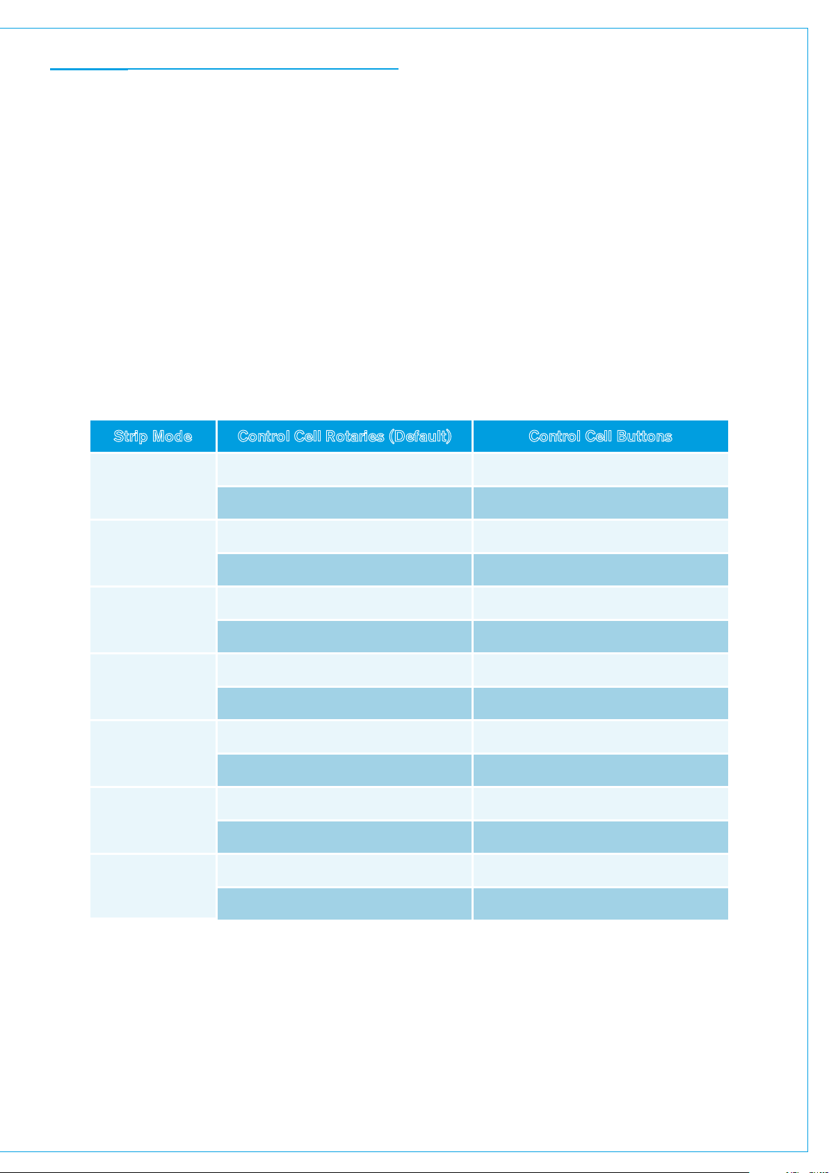
FIGURE 2 - CONTROL CELLS IN PAN CONTROL MODE
Strip Mode Controls
There are 14 strip modes in total. The controls associated with the upper and lower control cells are shown in the
following table:
Rotaries (Default) Control Cell Buttons
Strip Mode Control Cell Rotaries (Default) Control Cell Buttons
Input
Pan
Auto Mixing
Delay
Width
Path Outputs
Aux x/y
Input Trim (0 dB) Toggle Input 1 and 2
Input Balance (Centre) Toggles t hrough input leg routing
Left/Right Pan (Centre) Left/Right Pan On/Off
Front/Rear Pan (Front) Front/Rear Pan On/Off
Scroll through AutoMixer 1-4 or Off Select AutoMixer 1-4 or Off
Weighting Path to AutoMixer On/Off
Input Delay Value (0 ms) Input Delay Value On/Off
Path Delay Value (0 ms) Path Delay Value On/Off
- -
Stereo Width Range (Stereo) Stereo Width On/Off
Direct Output Level (0 dB) Direct Output AFL
Mix Minus Output Level (0 dB) Mix Minus Output AFL
Aux x Send Level (0 dB) Aux x On/Off
Aux y Send Level (0 dB) Aux y O n/Off
CALREC Putting Sound in the Picture 45
Page 46

PRESETS
A preset is a complete copy of a path from which you can choose elements to load onto another path. Using
presets can speed up workflow when several paths with similar settings are required.
When a new preset is made a full copy of the path is taken. Setting the scope of a preset defines which elements of the
path are copied to a path when the preset is loaded. The scope of the preset can be set at any time.
FIGURE 1 - PRESETS SCOPE
Creating a Preset
To create a preset from the currently accessed path:
1. Tap PATH PRESETS in the Access bar.
2. Navigate to where you wish to save the preset, making a new folder if necessary.
3. Tap NEW.
4. If you are overwriting a previously saved preset a red dialogue will be displayed to warn you of the potential overwrite.
Tap OVERWRITE or CANCEL. Otherwise, you will be directed to enter a label and description and set the scope of
the preset, then tap CREATE NEW PRESET or CANCEL to discard any changes.
FIGURE 2 - CREATING A PRESET
46 SUMMA Networked Audio Production System SYSTEM OVERVIEW
Page 47

Loading a Preset
To load a preset to the currently accessed path:
1. Tap PATH PRESETS in the Access bar.
2. Navigate to and select the preset that you wish to use.
3. Tap LOAD .
If you load a preset to a path which is part of the control link, the in-scope preset elements will be loaded for all paths in
the control link. Any elements of the preset which don’t apply to the path will be automatically ignored.
Backing Up and Restoring Presets
Presets can be backed up to a USB drive connected to one of Summa’s USB ports.
To back up a preset:
1. Tap PRESETS in the Access bar.
2. Navigate to and select the preset that you wish to backup from the list.
3. Tap BACKUP. You can now select multiple Presets from the same location if required.
4. Tap SELECT BACKUP LOCATION and ensure your USB drive is connected to one of Summa’s USB ports.
5. Navigate to your desired backup location, creating a new folder if necessary
6. Press BACKUP HERE or CANCEL. If you have previously saved a version of the same preset, a pop-up will appear
to ask if you wish to OVERWRITE or CANCEL the backup.
FIGURE 3 - BACKUP PRESETS
To restore a Preset from an external drive:
1. Press RESTORE and navigate to select the Preset that you wish to restore to the internal memory.
2. Press RESTORE or CANCEL.
Editing a Preset
Once a preset has been created you can edit its scope, label and description at any time by tapping PRESETS in the
Access bar, selecting the from the pop-up and tapping EDIT .
CALREC Putting Sound in the Picture 47
Page 48

Pooled Resources
When presets are loaded for ‘pooled’ resources, such as input and output delay modules, they will be assigned up to the
point where the pool runs out. If not enough resources are available to complete the load, a dialogue appears to tell you
that some resources have not been applied.
48 SUMMA Networked Audio Production System SYSTEM OVERVIEW
Page 49

COPY AND PASTE
It’s quick and easy to copy properties from one path and paste them to another:
1. Access the path that you wish to copy properties from and tap COPY in the Access bar.
2. Tap to select the properties that you wish to copy SELECT ALL and SELECT NONE can be used if required
and tap COPY or CANCEL .
3. Access the path that you wish to paste the properties to and tap PASTE in the Access bar.
FIGURE 1 - COPY PATH PARAMETERS
CALREC Putting Sound in the Picture 49
Page 50

LAYERS
The Summa surface has six layers allowing fader-control of 6 times as many paths as there are faders on the
surface. You can switch between layers using the layer selection buttons 1– 6 on the surface. Layer switching
options can be set per fader section. Fader sections can be ‘linked’, so that if a section’s layer is changed, the layer
will also change for all linked sections.
Layer linking options are set from the Surface Layer pop-up which is accessible from the Monitor bar along the bottom of
the Touch Display. This should be used along with Layer Switching Options which are located within Show settings.
When changing layer, all fader positions, button states and control cell states (if in a strip mode) change immediately to
reflect faders on the newly selected layer.
Layer Switching Options
To access layer switching options, tap SHOW SETTINGS in the Show menu and select ‘General’. One of these two
options can be chosen:
• Change the layer of all linked fader sections
• Change only the layer of the fader section containing the Accessed fader (any linked fader sections will also
change too)
The first option can be used if you wish to prevent a section of the desk from ever switching layers. For example, on a
Summa 36+8, linking sections 1, 2 and 4 and selecting the first layer switching option means that all surface sections,
other than section 3, will switch layers when surface layer buttons or pop-up layer buttons are pressed. Fader section 3
will stay on which ever layer you select for it within the Surface Layer pop-up.
The second layer switching option should be chosen if you always want the section containing the currently accessed
fader to switch layers (along with any linked surface sections) regardless of whether you have set some fader sections to
lock to a specific layer.
FIGURE 1 - LAYER SETTINGS
50 SUMMA Networked Audio Production System SYSTEM OVERVIEW
Page 51

Surface Layer Pop-up
Each surface section (12 or 8 fader) is represented along the top of the pop-up. Link layer switches along the bottom of
the pop-up can be set to ‘on’ or ‘off’ to enable or disable layer linking. Linked layers will always be on the same surface
layer.
FIGURE 2 - SURFACE LAYER Pop-up
CALREC Putting Sound in the Picture 51
Page 52

52 SUMMA Networked Audio Production System
SYSTEM OVERVIEW
Page 53

SUMMA
SETTING UP
calrec.com
Putting Sound in the Picture
Page 54

SYNCHRONISATION
It is essential that all elements of a Hydra2 network are synchronised to the same clock source.
The Summa processing rack has five synchronisation inputs and six levels of synchronisation source priority. The sixth is
always set to ‘internal reference’, so that, as a last resort, if all other sync sources fail, Summa can always run off its own
internal clock. If a clock source does fail, Summa will automatically jump to the next sync source in the priority list. One is
the highest priority, six is the lowest.
In ‘active Show’ view, the current sync source is always displayed
within the notifications area at the top right of the touch display.
Setting Synchronisation Source Priorities:
1. Tap SYSTEM SETTINGS in the top right of the touch display and select ‘synchronisation’ from the
menu.
2. Tap the selection cell for the sync priority level that you wish to alter. A pop-up appears with a scrolling menu
of possible sync sources. (The following figure shows the pop-up resulting from selecting sync source priority
4).
3. Tap to make your selection, scrolling down if necessary.
4. The pop-up closes and Summa refreshes and syncs to the highest priority viable source.
54 SUMMA Networked Audio Production System SETTING UP
Page 55

FIGURE 1 - SYNCHRONISATION OPTIONS
CALREC Putting Sound in the Picture 55
Page 56

Reset to First Source
It may sometimes be necessary to reset Summa’s synchronisation. To start the synchronisation reset process tap
RESET TO 1ST SOURCE. Summa will attempt to synchronise to each source in priority order, starting at priority one.
Once a viable synchronisation source is found the process will stop and the new sync source will display the ‘locked to’
tab as shown here.
FIGURE 2 - RESET TO FIRST SOURCE
56 SUMMA Networked Audio Production System SETTING UP
Page 57

Sources and Frame-Rates
Summa has 5 sync source options:
• Video 1
• Video 2
• AES3 (48 kHz)
• TTL Wordclock (48 Hz)
• Internal Reference
Summa supports the following frame-rates:
• PAL
• NTSC
• 720p/30
• 720p/29.97
• 720p/25
• 720p/24
• 720p/23.98
• 1080i/30
• 1080i/29.97
• 1080i/25
• 1080p/30
• 1080p/29.97
• 1080p/25
• 1080p/24
• 1080p/23.98
• 1080p/50
• 1080p/59.94
• 1080p/60
CALREC Putting Sound in the Picture 57
Page 58

ENERGY SAVER
Brightness
Summa’s energy saver settings allow you to control the brightness of all surface buttons and displays. There are three
rotary controls to independently set the brightness of buttons, small displays, and large displays. Drag these rotary
controls up and down to see the relevant brightnesses change.
Dark Mode
Putting Summa into dark mode turns off all lights across the surface apart from the surface reset LED, which pulses blue
to indicate that the console is functioning. Dark mode has no effect on audio or operation.
Dark mode can be set to activate after a specified duration of inactivity, ranging from one minute, to an hour.
Alternatively you can select NEVER.
FIGURE 1 - ENERGY SAVER SETTINGS
58 SUMMA Networked Audio Production System SETTING UP
Page 59

GENERAL SETTINGS
To access Summa’s general settings, ensure the touch display is in ‘active Show’ view and tap SYSTEM SETTINGS
in the top right of the screen and then select ‘general settings’ from the menu on the left hand side. To edit these
settings you must be logged in as an administrator.
General Settings
The following general settings are available:
• The analogue level at 0 dBFS can be calibrated to 15, 18, 20, 22, 24 or 28 dBu.
• The reference level (dBFS) can be set to an integer value between -6 and -32 dBFS. The reference level sets default
level values for the dynamics and oscillator modules.
• The point at which the input impedance changes between mic and line level can be set to 18, 20, 22 or 24dBu.
• The mic input headroom for the system can be chosen. Options range from 20 dB to 36 dB.
• The default meter style can be set for all meters on the meter displays. PPM or VU scales can be chosen along with
various colour split points, controlling the level ranges of the green, yellow and red elements of the meter bar graphs.
• Cut/on button functionality can be set: With cut selected, paths are cut when cut/on buttons are active; with
on selected, paths are switched on when the cut/on buttons are active, and so paths are cut when cut/on buttons are
not active.
• If you have not routed the PFL bus to the console monitors, you can choose to route it to the small LS, rather than
using the dedicated PFL LS output.
• When faders are under CSCP control, this can be overridden when the fader is touched; Summa’s faders are
touch sensitive. This feature can also be disabled.
• You can choose whether or not to report system status messages for the redundant core modules.
If you have chosen a Summa with 128 channels and no redundancy you should set this to OFF.
CALREC Putting Sound in the Picture 59
Page 60

FIGURE 1 - SYSTEM SETTINGS—GENERAL
Surround Leg Suffixes
You can enter suffixes to be automatically displayed at the end of the individual legs of surround path port labels within the I/O patching screen. Suggested suffixes are L, R, C, LFE, Ls, Rs. These suffixes help to keep the surround legs
together and in the correct order when sorting tables within the I/O patching window.
FIGURE 2 - SURROUND LEG SUFFIXES
60 SUMMA Networked Audio Production System SETTING UP
Page 61
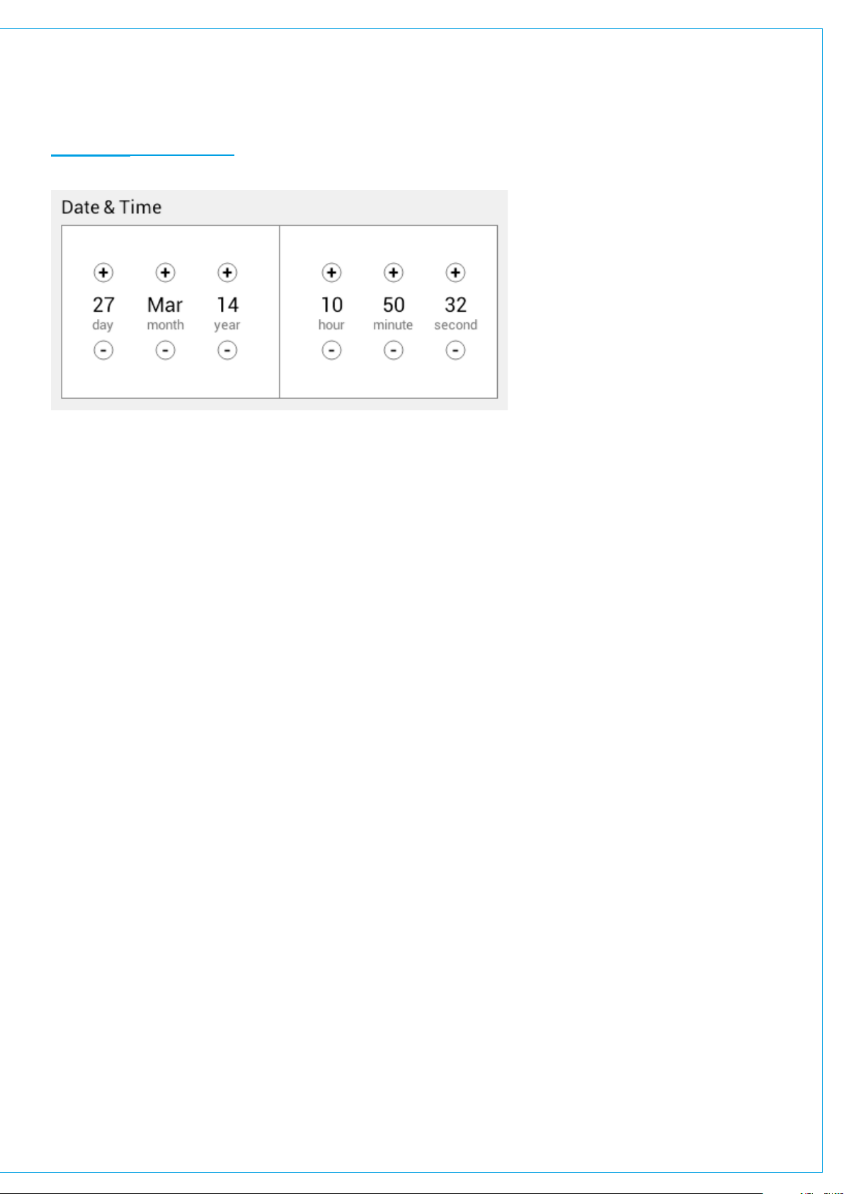
Date and Time
The current date and time are displayed towards the bottom of the general settings.
FIGURE 3 - DATE AND TIME
CALREC Putting Sound in the Picture 61
Page 62

EDITING THE NETWORK
All I/O resources on a Hydra2 network can be used by all consoles as long as they have been granted
access from the network administration tool, H2O, and the resources have been added to the consoles
‘required list’.
Due to the scalable nature of Hydra2 you may have access to a large amount of I/O resources, some of which you won’t
always need. The ‘required list’ provides a way to narrow the scope for individual consoles, speeding up workflow and
making port identification easier. Only I/O resources in the ‘required list’ will be available for patching to and from the
console.
Viewing Resources
Tap SYSTEM SETTINGS in the top right of the touch display, then select ‘Required I/O Boxes’. You will see a split
screen with all online resources on the left and the ‘required list’ on the right.
Both lists are held in tables with 3 columns: Hardware ID, label and type. It may help to sort these tables by tapping on
column headers. Multiple taps will switch sorting to be either ascending or descending.
Hardware IDs for physical I/O boxes are set from the dip switches on the back of the units (See “Audio I/O Connections”
in the Installation manual for more information). Hydra patchbay IDs are taken from H2O and are related to folder names.
Labels are explained in detail, here: “Input and Output Patching” on page 81.
FIGURE 1 - ACCESSING SYSTEM SETTINGS
Tap to select a single online resource on the left (hold and drag or drag handles to select multiple resources) then
tap ADD TO REQUIRED LIST at the bottom left of the online resources window. The resources will then appear
in the Required List on the right. You will notice that they are shaded green, with a green ‘required’ tag attached.
This is mirrored in the online list on the left so you can quickly see which resources you have already added. If any of the
resources in the Required List go offline, they will be shaded red with an ‘offline’ tag attached. The ‘require’ and ‘offline’
tags can be seen in the image below.
62 SUMMA Networked Audio Production System SETTING UP
Page 63

Adding and Removing Resources
To remove a resource from the list, select it, then tap REMOVE FROM REQUIRED LIST.
FIGURE 2 - THE ‘REQUIRED LIST’
CALREC Putting Sound in the Picture 63
Page 64

SHOWS
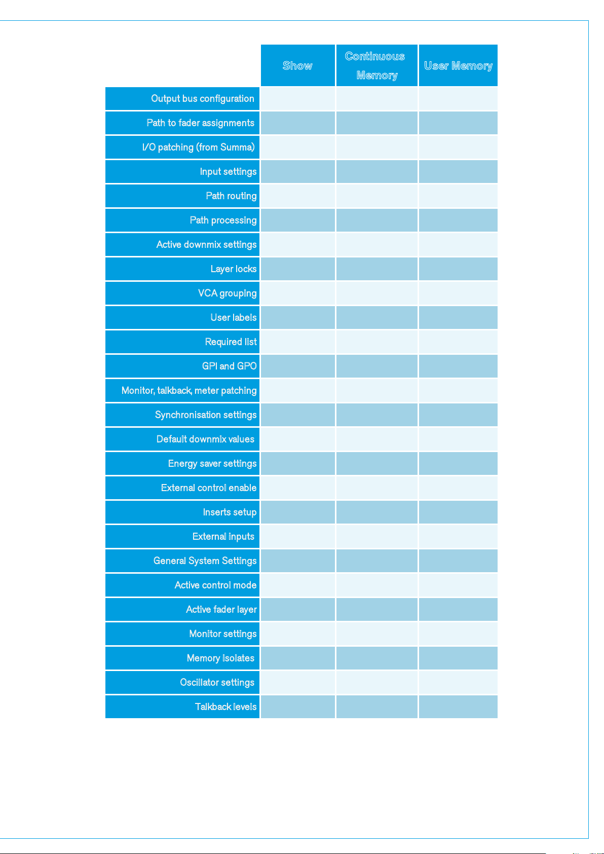
Summa uses a system of Shows, user memories and continuous memory to store settings for later recall.
Shows are used to organise user memories into sub-categories making them easier to manage, rather than having
to search through a long list of varied memories each time, you can select a Show and view the user memories
associated with that Show.
A possible use for this would be to create Shows for each type of production, e.g. ‘Morning News’, ‘Football’, ‘Chat Show’
etc. and then create multiple user memories within each Show for different users and situations. Before saving multiple
memories into a Show, it is good practice to create one default user memory, test it, and use it as a template to create
multiple user memories. This avoids the repetitive and time consuming task of having to make the same changes to
multiple memories.
During operation, Summa constantly updates its continuous memory, which is also saved within the currently active Show.
When a Show is recalled, it is this continuous memory that is recalled, not a user memory.
Note, loading a Show recalls the last-used settings, not the last-saved settings.
FIGURE 1 - SHOWS AND MEMORIES
64 SUMMA Networked Audio Production System SETTING UP
Page 65
Show
User Memory
Memory
Output bus configuration X X
Path to fader assignments X X
I/O patching (f rom Summa) X X
Inp ut settings X X
Path ro uting X X
Path pr oces sing X X
Active downmix settings X X
Layer locks X X
VC A grouping X X
User labels X X
Required list X
Continuous
GPI and GPO X
Monitor, talkback, meter patching X
Synchronisation settings X
Default downmix values X
Energy saver settings X
External control enable X
Inserts setup X
External inputs X
General System Settings X
Active control mode X X
Active fader layer X X
Monitor settings X X
Memory isolates X X
Oscil lator settings X X
Talkback levels X X
CALREC Putting Sound in the Picture 65
Page 66

Entering the Shows List
Tap SHOWS LIST to the top left of the touch display. All available Shows are presented within a sortable table.
To return to ‘active Show’ view, tap ACTIVE SHOW in the top right of the touch display.
FIGURE 2 - ACCESSING THE SHOWS LIST
Active Show
The Show that is currently active is identified by the ‘active’ tab.
Loading a Show
Locate and select the Show you wish to load, then tap LOAD in the control window footer, then LOAD again to confirm
your choice.
Setting up a New Show
All new Shows are based on pre-configured Show templates. To set up a new Show:
1. Tap NEW in the control window footer.
2. Pick a template within the ‘new Show’ pop-up.
3. Enter a label and some details for the Show and tap CREATE SHOW.
The client and series text fields will already be populated for you as they are taken from the template.
66 SUMMA Networked Audio Production System SETTING UP
Page 67

Duplicating a Show
Duplicating Shows can save time when several very similar Shows are needed:
1. Select a Show and tap DUPLICATE in control window footer.
2. Enter a new label.
3. Tap DUPLICATE or CANCEL.
Deleting a Show
1. Tap to select one or more Shows within the list.
2. Tap DELETE in the control window footer.
3. Tap DELETE SELECTED, or CANCEL.
Editing a Show
Once a Show has been created it is possible to edit its label and description:
1. Select the Show that you wish to edit and tap EDIT in the control window footer.
2. Make changes to the label and description in the pop-up.
3. Tap SAVE or CANCEL .
Moving Shows between Summa Systems with 180 and 128 channels
When moving a show from a 180 channel Summa to a 128 channel Summa, it is possible that some channels cannot be
created due to the smaller DSP capacity. The user is notified about which channels were not created, allowing them to
understand how the mix will be affected.
Summa also supports moving shows between systems with different surface sizes. If the user loads a show made on a
large surface, onto a surface with fewer faders, they will have access to virtual fader sections, allowing the user to move
the inaccessible paths onto faders and layers that they can access on the smaller surface.
Show Templates—Admin Only
Whenever you create a new Show it must be based on a template. The generic Calrec template is always available.
Additional templates can be created by Summa administrators. Show templates hold the same data as Shows but they
cannot be opened, edited or deleted without logging in as an administrator.
Setting Up and Editing Templates—Admin Only
Enter the shows list screen and tap SHOW TEMPLATES to the left of the window header. You are required to enter
the admin username and password for the system you are using, then tap LOG IN and you have access to the available
Show templates.
From here you can create a new template by tapping NEW and entering client, series and label information. You
can delete a template (other than the Calrec default template) by selecting it and tapping DELETE . You can edit a
template’s details by selecting it and tapping EDIT .
Updating Templates—Admin Only
You can update Show templates to reflect the current System Settings by tapping UPDATE. You will then be asked to
confirm or cancel the update.
CALREC Putting Sound in the Picture 67
Page 68

Backing Up Shows
Shows and their user memories can be backed up to a USB drive connected to one of Summa’s USB ports. To back up
a Show:
1. Select the Show that you wish to backup from the Shows list.
2. Tap BACKUP toward the bottom right of the display. If you wish to select multiple Shows, select them all now.
3. Tap SELECT BACKUP LOCATION and select a destination for your back up, making a new folder if necessary.
4. Tap BACKUP HERE or CANCEL. If you have previously saved a version of the same Show a pop-up will appear
to ask if you wish to OVERWRITE the show or CANCEL the backup.
Restoring Shows
1. Tap RESTORE in the footer of the Shows List and navigate to select the Show that you wish to restore.
2. Tap RESTORE.
FIGURE 3 -
Capacity
BACKING UP SHOWS
The “Capacity Used” bar-meter, below the Shows list, shows the amount of space available on the controller card for
storing Shows and Memories, however, the controller card memory is also used for other files and folders and so the
capacity may vary.
Settings Stored within Shows
Tap Show Settings within the Show menu on Summa’s touch display and you will see four options: General, Delay
Controls, Downmix and External Inputs.
68 SUMMA Networked Audio Production System SETTING UP
Page 69

General Settings:
• By default, a notch can be felt at the ‘0’ point on the fader scale. This can be switched off if required.
• The surface layer buttons can be set to operate in one of two ways. They either change all linked fader sections or
only the sections which contains the accessed fader, plus any sections which are linked to that section.
• By default, PFL can be activated momentarily by pulling the fader down below its lowest point, and deactivated once
released. This feature can be switched off for the whole surface.
• By default, if a fader is closed and it’s PFL is activated, it will be automatically deactivated once the fader is opened.
This feature can be switched off for the whole surface. (see “PFL, AFL and Output Listen” on page 111).
• VCA groups are generally made and dissolved by pressing fader access buttons but this process can be disabled to
protect all VCA assignments or to stop VCA groups being made accidentally.
• By default, VCA slave faders move automatically when their levels are changed by their masters. If you would rather,
this functionality can be switched off and instead slaves will remain stationary. Combined master/slave levels will still
be indicated by the nulling indicators in the fader displays. (see “VCA Groups” on page 142)
Other settings are explained in the relevant sections: “Delay” on page 138 , “Downmixing” on page 167 and
“External Inputs” on page 93
FIGURE 4 - SHOW SETTINGS
CALREC Putting Sound in the Picture 69
Page 70

MEMORIES
User memories are files which store processing, routing and patching information which can be recalled at any
time.
Loading a User Memory
1. Tap MEMORIES in the Show menu and you will see a list of all user memories that are available within the
current Show.
2. Tap to select the user memory that you wish to use and tap LOAD .
3. The footer changes to ask for confirmation, tap LOAD SELECTED or CANCEL.
Creating a new User Memory
To create a new user memory with current surface settings:
1. Tap NEW in the memories window footer.
2. Enter a name and a short description for the new user memory.
3. Tap CREATE or CANCEL .
Updating a User Memory
To update a previously saved user memory with the current surface settings:
1. Select the user memory that you wish to update and tap UPDATE in the memories window footer.
2. You will be prompted to confirm by tapping either UPDATE SELECTED, or CANCEL.
Creating Multiple User Memories
Best practice is to create one ‘default’ user memory, test it, make any necessary changes, and then use this as the
basis for all other user memories within the Show. This speeds up the process by reducing the need to make the same
changes to many different user memories.
To do this, create, test and update what is to be the ‘default’ user memory as described above, then, with the this user
memory still loaded on the surface, tap NEW, and the information will be saved into a new user memory, effectively
duplicating it.
Storage Capacity
There is a capacity indicator at the top of the memories window which shows how much storage space is available.
If you require more space, delete any old Shows and user memories which are no longer needed. The capacity indicator
shows the amount of space available on the controller card for storing Shows and Memories, however, the controller card
memory is also used for other files and folders and so the capacity may vary.
70 SUMMA Networked Audio Production System SETTING UP
Page 71

FIGURE 1 - MEMORY CAPACITY
Memory Isolation
Memory Isolation is a system whereby paths or individual path parameters can be protected from being updated when
a user memory is loaded. When in ‘active Show’ view, memory isolation options are available per-path from the ISO
drop-down menu in the right hand side of the access bar: use the drop-down menu to select which parameters you
wish to isolate for the currently accessed path. ISOLATE ALL or ISOLATE NONE options are also available.
Note: From version 3.2 onwards Paths that have been isolated from memory loads can be moved around the surface.
CALREC Putting Sound in the Picture 71
Page 72

FIGURE 2 - LOCATION OF ISOLATION CONTROLS
The Isolation status of each path is indicated on its fader display—a blue ISO icon indicates a fully isolated path and a
green ISO icon indicates partial isolation is in operation for that path.
FIGURE 3 - ISO ICONS
72 SUMMA Networked Audio Production System SETTING UP
Page 73

The following settings can be isolated:
• Input 1 ports
• Input 1 parameters
• Input 2 ports
• Input 2 parameters
• EQ Settings
• Dynamics 1 settings
• Dynamics 2 settings and Automixer
• Insert
• Fader position
• The VCA master status of the fader
• The VCA slave status of the fader
• Downmix settings
• Path width settings
• Replay settings
• Main/Group routing
• Main/Group Pan
• Aux routing sends and pan
• Mix Minus routing
• Mix Minus send
• Auto Minus routing
• Direct Output parameters
• Direct Output ports
• Mix Minus parameters
• Mix Minus output ports
• Path delay
• Path flow
• Path width
• Path output ports
CALREC Putting Sound in the Picture 73
Page 74

74 SUMMA Networked Audio Production System
SETTING UP
Page 75

SUMMA
GETTING SIGNALS IN AND OUT
calrec.com
Putting Sound in the Picture
Page 76

FADER LAYOUT
The first stage of passing audio into the Summa system is to attach a channel to a fader. Audio feeds to Hydra2 input
ports must be attached to channels in order to be processed and routed; channels must be attached to faders to exist.
Faders can be used to control channels, mains, groups, aux masters and track masters.
Tap FADER LAYOUT in the Show menu. You will see a visual representation of all faders on all six layers—drag in any
direction to view the entire screen. The image below shows examples of all path types as viewed in the fader layout
screen.
FIGURE 1 -
THE FADER LAYOUT SCREEN
76 SUMMA Networked Audio Production System GETTING SIGNALS IN AND OUT
Page 77

Attaching a Path to a Fader
To attach a path to a single fader:
1. Tap an empty fader space to select it.
2. Tap NEW in the control window footer.
3. A pop-up opens to show all path options, ranging from different widths of channel to mains, groups, auxs and
tracks. Tap to select the desired width/type and the pop-up closes, or tap CANCEL to return to the fader layout
screen without making any changes.
To attach paths to multiple faders:
1. Either hold and drag or tap and drag selection handles to select the desired range of faders.
2. Tap NEW and select your path/width choice from the pop-up. All selected faders will then be populated with the
chosen path type/width. If a main, group, aux or track is chosen, the selected faders will be populated with buses
in consecutive order. For example, if you select four faders, and then choose aux master 4, the faders will be
populated with aux masters 4, 5, 6 and 7.
FIGURE 2 - FADER LAYOUT — NEW PATH POP-UP
Settings
Tap SETTINGS in the bottom right of the fader layout window and a pop-up appears containing settings for controlling
how information is displayed. The top half allows you to set how fader/port labels are displayed. Tap to select which of
the three label types you would prefer to view. Your choice of label type will then be displayed if possible, if not, the next
type in the priority order will be displayed, and so on.
The bottom half of the pop-up, ‘surface interaction’, provides two check box options:
• SCREEN FOLLOWS LAYER SELECTION allows the screen to scroll, bringing the selected layer into focus.
• SCREEN SELECTION FOLLOWS FADER ACCESS allows the screen to scroll to bring the currently
accessed fader into focus.
CALREC Putting Sound in the Picture 77
Page 78

FIGURE 3 - FADER LAYOUT SETTINGS
78 SUMMA Networked Audio Production System GETTING SIGNALS IN AND OUT
Page 79

Editing Labels
To edit a user label:
1. Select one or more faders and tap USER LABEL . The footer changes to display a text entry field and four
buttons, PREVIOUS, NEXT , DONE, CANCEL .
2. Enter fader labels using either the software keyboard or an external keyboard connected via one of the three
surface USB ports.
3. Scroll through the fader label fields by tapping them, or by tapping PREVIOUS and NEXT .
4. Once you are happy with your changes, tap DONE .
Port Labels
User Label:
A label given to a port/path/bus from the Summa interface. This is only viewable on the console that it was made on.
Port User Label:
A label given to a port by the network administrator via H2O. This label is viewable across the Hydra2 network.
System Label:
A port label generated within an I/O box and viewable across the Hydra2 network.
Cloning Paths
To clone a path:
1. Select one or more faders, at least one of which must have a path attached.
2. Tap CLONE in the control window footer.
3. Tap the fader(s) to which you wish to clone the selected path(s).
4. Tap CLONE again to confirm your choice.
As you tap possible destinations, previews of the potential placements appear to help with your decision. A colour
indication system is used to indicate the possible outcome of your choice: green when the destination is empty, orange
when a path other than a channel is assigned to the fader, and red when a channel path is assigned to the fader.
Red is used to indicate channel paths because if a channel is removed from a fader it no longer exists.
Once you have selected your destination you are presented with two options, CANCEL or CLONE & OVERWRITE
which replaces the destination path with a clone of your original selection and removes the original path(s) from the
surface. As channels don’t exist once they are removed from faders, a pop-up appears if you attempt to overwrite a
channel, requiring you to confirm your choice.
Moving Paths to Different Faders
1. Select one or more faders, at least one of which must contain a path.
2. Tap MOVE in the control window footer and tap the fader that you wish to move the selected paths to.
3. Tap MOVE again to confirm your choice.
CALREC Putting Sound in the Picture 79
Page 80

Alternatively, once your chosen faders are selected, touch and hold again to make your selection float over the fader
layout screen. From here drag your selection across the screen to your desired location. As you tap or drag across
possible destinations, previews of new path placements appear to help with your decision. The colour indication system
described above is used.
Once you have selected your destination you are presented with three options: CANCEL; SWAP—swaps the original
paths with those on the chosen destination faders; OVERWRITE —replaces the destination path with your original
selection and removes the destination paths from the surface. As channels don’t exist once they are removed from a
fader a pop-up appears if you attempt to overwrite a channel requiring you to confirm your choice.
Deleting Paths from Faders
To remove a path from a fader:
1. Select one or more faders, at least one of which must have a path attached.
2. Tap DELETE in the window footer.
As channel paths don’t exist once they are removed from faders, if you attempt to delete a channel, a pop-up appears
showing the paths that you are attempting to delete, requiring you to confirm your selection.
Lock a Fader to the Surface
Layer lock allows you to ensure some faders are always present on the surface, regardless of which layer is selected.
1. Select one or more faders (with or without paths attached).
2. Tap LOCK in the window footer.
The selected faders are then locked to the surface and will remain there regardless of layer selection.
80 SUMMA Networked Audio Production System GETTING SIGNALS IN AND OUT
Page 81

INPUT AND OUTPUT PATCHING
Summa desk inputs and outputs can be patched to physical I/O box ports or virtual Hydra patchbay ports, or to
each other. To enter the I/O patching screen, tap ‘I/O patching’ in the Show menu.
Patches are made between sources and destinations.
• A source can be an I/O box input port, a Hydra patchbay output, or a desk output from the local Summa console.
• A destination can be an I/O box output port, a Hydra patchbay input, or a desk input from the local Summa console.
Each source can be patched to multiple destinations but a destination can only have one source. When patching an
input port to multiple input channels it is important to remember that phantom power (48 V), input gain and sample rate
conversion are all set within the Hydra2 domain and so altering these controls from any point on the surface will affect that
feed for every instance of it across the surface and across the Hydra2 network.
The I/O Patching Window
The I/O patching window is split into two halves, sources are displayed on the left and destinations on the right. Each
side has a series of buttons running along the top for you to select which source/destination type you wish to access.
Selecting Sources and Destinations
Tap a source or destination selection button and a pop-up reveals all available options of that type, either as a set of
buttons, or, in the case of I/O boxes, within a sortable table. Tapping to select one of these options, i.e. ‘Aux Outputs’,
populates the source/destination window with the associated ports.
FIGURE 1 - I/O PATCHING WINDOW—SELECTING A PORT TYPE
CALREC Putting Sound in the Picture 81
Page 82

Understanding Ports
The images below show how different port types are displayed within the I/O patching screen.
FIGURE 2 - PORT TYPES AS VIEWED IN THE IO PATCHING WINDOW
Port groupings are always displayed within sortable tables under the following headings:
Numbers
The port number is a combination of the I/O box hardware ID (HID) and the port number within the box—See H2O user
guide for more detailed information. This is the port’s native label and is generated directly from the I/O box itself.
Port labels
The port label can be either the user label, the port user label or the system label. See the port labels information box on
this page for more information.
Description
The network administrator can include a brief description of a port, if so, this will be included in the I/O patching screen
table. The description cells can be changed to display the connected source/destination if preferred.
Connected Source/Destination
The label of the source/destination that is connected to the port is displayed.
82 SUMMA Networked Audio Production System GETTING SIGNALS IN AND OUT
Page 83
Icons
The following icons can be displayed in the I/O patching window:
This symbol will be displayed if you have been denied access to the port via H2O by the network
administrator.
Whenever a port goes offline this icon is displayed.
If a port has been patched to/from by another Hydra2 user this icon is displayed.
If a port has been patched to/from via H2O this icon will be displayed.
If a port has been patched via a 3rd party controller this icon will be displayed.
Within the I/O patching window, sources and destinations have separate settings, which are accessible from the
left and right of the control window footer. The available settings vary depending on which port type is in view:
Channel Settings
If channel inputs are in view, you can globally switch between viewing input 1 or input 2.
Layer View
When viewing fader specific paths, such as channel inputs or fader inserts, layer view options will be available.
Select layers 1–6 to view only faders on that layer, or select SURFACE LAYER to view the layer which is currently
active on the surface.
Surface Interaction
When viewing fader specific paths, such as channel inputs or fader inserts, surface interaction options are available.
Checking the FADER SELECTION FOLLOWS FADER ACCESS check box brings the currently accessed fader
directly into view within the I/O patching screen at all times.
Connected Destination
You can view connected destinations from sources and view connected sources from destinations. Both are displayed
within the centre columns with this option selected.
Information Display
When viewing Hydra patchbays or I/O boxes, the information display split-selection button is available to choose
between viewing path descriptions or connected source/destinations within the two centre columns of the screen.
CALREC Putting Sound in the Picture 83
Page 84

FIGURE 3 - SETTINGS POP-UP
Viewing and Sorting
Ports are displayed within sortable tables. The sorting options vary between port types:
• Fixed format and modular I/O boxes can be sorted by number (native label), port label or description (if available).
To keep I/O boxes together in the viewing table, sort by ‘number’ as this includes the box’s HID which will be the
same for all ports in that I/O box.
• Hydra patchbays can be sorted by patchbay name or patch-point number.
• Desk connections can only be sorted by resource number e.g. main 1 to 4.
In order to keep the individual legs of a 5.1 path together within the display you can add a suffix to each leg, for example
L, R, C LFE, Ls, Rs. See “General Settings” on page 59 for more information.
Making a Patch
To patch a source to a destination:
1. Select a source type from the source window header.
2. Select a destination type from the destination window header.
3. Tap to select a source.
4. Tap to select a destination.
5. Tap CONNECT.
Moving a Destination
Once a patch has been made, the destination can easily be changed:
1. Select a destination.
2. Tap MOVE in the window footer.
3. Select an alternative destination, (at this point you can select a new destination type).
4. Tap MOVE once more.
84 SUMMA Networked Audio Production System GETTING SIGNALS IN AND OUT
Page 85

Protect a Patch from Memory Loads
Patches can be ‘fixed’, isolating them from memory load changes. Fixed patches are also protected under the port
protection system in the same way as ports which are in use by multiple Hydra2 network users (See “Source and
Destination Protection” on page 89).
To Fix a patch:
1. Select one or more patched destinations.
2. Tap FIX in the window footer.
3. To un-fix the patch, tap FIX again.
Isolating a Patch
Isolating a patch protects it from changes due to memory loads, but it differs from patch fixing in that patch isolation only
relates to actions performed on the local Summa console. Isolated patches can still be over-patched by other Hydra2
users and by memory loads on other consoles on the network.
To isolate a patch:
1. Select one or more patched destinations.
2. Tap ISO in the window footer.
3. To de-isolate the patch, tap ISO again.
Removing a Patch
To remove a patch from the system:
1. Select either the source or destination (or one of the destinations if the source is patched to more than one).
2. Tap REMOVE in the window footer. The patch is automatically removed, unless it is ‘fixed’ on the surface or
was made by another Hydra2 user, in which case a pop-up appears requiring confirmation of the removal.
Inputs 1 and 2
Every Summa channel has two inputs, 1 and 2, to which two entirely separate feeds can be patched. Input 2 is generally
used for patching a back-up microphone so that if the feed to input 1 fails, you can quickly switch to use input 2, which
has exactly the same processing, routing and output patching applied to it as input 1.
Patching Outputs to Inputs
Desk outputs and buses can be connected directly back into channel inputs. This method of control is different to just
attaching a console output to a fader. From the I/O patching screen select DESK OUTPUTS in the sources window
and DESK INPUTS in the destinations window and patch as normal.
CALREC Putting Sound in the Picture 85
Page 86
INPUT CONTROLS
With the touch display in ‘active Show’ view, tap the input processing tab to view all input controls for the currently accessed channel or group.
Depending on the type of input port that is connected to a channel, you will see some or all of the controls described
here. The input controls window is split into three sections, the header contains general controls, the physical I/O box
port controls are on the left and Summa’s channel controls are on the right. In the control window header the Input 1 /
Input 2 toggle button allows you to switch between two entirely separate I/O box input ports which may be patched to the
currently accessed path. The tone switch toggles tone on and off to the channel.
I/O Box Input Port
Controls and information fields on the left of the Input window relate to the physical I/O box input port; at the top, the
port’s native/user label is displayed. The rotary control and switches control mic/line gain and phantom power
settings for the connected physical input port.
If the port is shared with other Hydra2 network users this will be indicated, as shown in the image below, with a padlock icon
along with a list of all network users who are sharing the port. The
altering shared port controls, see
“Source and Destination Protection” on page 89 for more information.
ENABLE TEMPORARY CONTROL button is used when
The Channel Input
The channel input controls on the right of the screen control the DSP settings within the Summa processing core for the
currently accessed path:
• Input Trim increases or reduces the level of the incoming signal between -24 dB and +24 dB.
• There are polarity invert switches for each leg of the path.
• If a stereo path is accessed, a middle and side (M/S) decoder will be available. Switching this on automatically
treats the incoming stereo signal as a middle and side microphone array.
• Input balance allows you to alter the weighting of the stereo signal between the left and right legs of the path.
• Path leg routing options L TO LR and R TO LR allow you to route the left or right legs to both sides of a stereo
channel. With both switches in the off position the left signal feeds the left leg and the right signal feeds the
right leg of the stereo path, this is a ‘normal’ stereo setup. Switching L TO LR to the on position feeds the
left signal to both left and right sides of the stereo path, and switching on R TO LR feeds the right portion of
the signal to both left and right sides of the stereo path. Switching both switches on sums the left and right
portions of the signal together and outputs this on both the left and right legs. With both switches in the same
position, either on or off, you have access to the input balance control. When they are both off the balance
control responds as described above but with both controls switched on the it is a full range balance control
i.e turning the dial all the way to the left just outputs the 0 dB left hand signal from the left leg of the path.
With either L TO LR or R TO LR switched on independently, the balance control is unavailable—it would have
no effect as the left and right portions of the signal would be the same.
86 SUMMA Networked Audio Production System GETTING SIGNALS IN AND OUT
Page 87

FIGURE 1 - INPUT CONTROLS
Input Control Mode
Push the INPUT control mode button on the surface to populate each pair of control cells with input controls for the
fader below. The top control cell is for controlling input trim and the button switches between input 1 and 2. The bottom
control cell controls input balance for stereo paths, the button toggles through the various path leg routing options.
The balance control is only operational with both path leg routing options either on (mono) or off (stereo).
FIGURE 2 - CONTROL CELLS—INPUT CONTROL MODE
CALREC Putting Sound in the Picture 87
Page 88

Mic/Gain
If the gain of any connected mic/line input is not the same on all legs of a stereo or surround channel, then the gain display will show the highest and lowest value for surround sources, left and right values for stereo sources , as highlighted
below:
FIGURE 3 -
Group Input Controls
MIC/GAI
N
When a stereo or mono group is accessed an input trim control is available from the input window as shown below.
Path leg routing buttons are also provided for stereo groups:
FIGURE 4 - GROUP INPUT CONTROLS
Linking Input 1 and Input 2 Trims
Inputs 1 and 2 have separate input trim controls . These can be linked from the Tools menu on the Access> Input screen
as shown in Figure 5 below. The wording on the Control Cell changes to show the words ‘Trims Linked’ between the
Input 1 and Input 2 source identifiers. The display on the screen also shows the fact that the Input trims are linked.
88 SUMMA Networked Audio Production System GETTING SIGNALS IN AND OUT
Page 89

FIGURE 5
Replay
Replay allows the user to select a number of channels to switch between input 1 and input from one control which can
be a user button or be controlled from the screen. This is also achieved from the Tools menu on the Access>Input screen
shown in Figure 5 above. The user then selects paths for replay using the ACCESS keys. see Figure 6 below.
The fader displays change to say ‘REPLAY’ rather that not in replay’ as appropriate.
-LINK TRIMS
FIGURE 6
When Replay is active these channels will switch to Input 2 , when Replay is turned off the input channels switch back
to input 1. Replay makes setting up a virtual soundcheck easy. With the sources connected to input 1 each source is
sent to a recorder and its returns are connected to input 2. When the talent leaves the user can turn replay on play the
recording and continue the soundcheck. On completion the replay is turned off to switch all the inputs back to the live
sources. Note: Replay can also be controlled from a GPI if required. Figure 7 shows system in Replay.
FIGURE 7
-REPLAY CHANNEL SELECTOR
-SYSTEM IN REPLAY
CALREC Putting Sound in the Picture 89
Page 90

SOURCE AND DESTINATION PROTECTION
Source and destination protection is a simple system using pop-ups and buttons to protect input parameter
settings and output destinations when ports are in use by multiple users across a Hydra2 network.
When viewing inputs on Summa, you will notice if it is being shared, as the following label will be displayed:
FIGURE 1 - INPUT PROTECTED
90 SUMMA Networked Audio Production System GETTING SIGNALS IN AND OUT
Page 91

The same protection applies if the port has been ‘protected’ within H2O, if this is the case, the following will be displayed:
FIGURE 2 - INPUT PROTECTED BY H2O
Destination Protection
The image on the next page shows the I/O port patching screen during the process of making a source to destination
connection. A ‘traffic-light’ colour coding system is used. The coloured arrows indicate any issues associated with the
potential source to destination patch.
• A green arrow indicates that there is no source currently connected to the destination so the patch can be made
with no issues.
• The yellow arrow indicates that currently the destination has a local source connected to it.
• The red arrow indicates that the destination has had a source patched to it by another user on the network.
• The grey arrow indicates that the patch will not be made because you have been denied access to the port by the
network administrator.
If you decide to go ahead with the patch and the indication arrow is either red or yellow, the protection pop-up shown
below will appear as an extra level of protection, allowing you to review all potential changes before committing.
CALREC Putting Sound in the Picture 91
Page 92

FIGURE 3 - PROTECTION ARROWS
Source Protection
Audio sources can be shared by all consoles on the Hydra2 network. Source protection adds an layer of protection when
making changes to the following input controls:
• Mic/line gain.
• Phantom power (48 V).
• SRC (if using AES sources).
As indicated in the input control window, to make changes to these protected input controls, simply tap ENABLE
TEMPORARY CONTROL , then make the desired changes. This remains active until you touch any control outside the
input window, at which point it will need to be activated again to make any changes to the protected input controls.
User Memory Load Protection
Loading a user memory will generally include changes to patching and input controls, if these changes affect shared/
protected inputs, or patching to outputs which are already in use by other users on the network, source and destination
protection will come into play.
When a user memory with conflicting settings/patching is loaded, a pop-up, like the one shown below, is displayed on
the touch display. The number of pages within the pop-up depends on whether there are conflicts relating to sources,
destinations or both.
Once you have checked all conflicts and selected those that you wish to accept, tap OVERWRITE SOURCE &
DESTINATION SETTINGS. Tapping DON’T MAKE ANY CHANGES rejects all changes to shared sources and
destinations, but makes all other changes associated with the memory load.
Ensure that you fully understand the effect of any accepted changes as you will be directly affecting other users
on the network.
92 SUMMA Networked Audio Production System GETTING SIGNALS IN AND OUT
Page 93

FIGURE 4 - SOURCE AND DESTINATION POP-UP—MEMORY LOAD
CALREC Putting Sound in the Picture 93
Page 94

EXTERNAL INPUTS
Summa has a pool of 152 mono external input resources from which you can create any combination of mono, stereo and
5.1 inputs, using one, two or six resources respectively. External inputs can be monitored and metered and are available
as patching destinations within the I/O patching window.
External inputs are typically used to monitor down-stream feeds or ‘off-air’ returns to ensure the console output is not
being compromised on its way to its intended destination.
To view the external inputs window, tap SHOW SETTINGS at the bottom of the Show menu, then tap EXTERNAL
INPUTS.
Creating External Inputs
Within the external inputs window, select one or more cells using one of the following options:
• Tap to select a single cell.
• Touch and drag to select multiple cells.
• Tap, then drag selection handles to select multiple cells.
... then tap NEW.
Select a path width from the pop-up—mono, stereo and 5.1—and your selected cells are populated with your choice.
Note, within the pop-up the number of remaining external input resources is displayed.
FIGURE 1 - CREATING EXTERNAL INPUTS
94 SUMMA Networked Audio Production System GET TING SIGNALS IN AND OUT
Page 95

Removing External Inputs
To remove external inputs:
1. Select one or more external input cells using one of the methods described above.
2. Tap DELETE .
3. A pop-up appears showing all external input paths to be deleted, tap DELETE to accept. The deleted
resources are returned to the resource pool to allow more external inputs to be created.
Labelling External Inputs
By default, external inputs have labels which correspond to the cell that they were created in, for example “External Input
5” in cell 5. You may wish to add your own labels. To do this:
1. Select one or more external inputs using one of the methods described above.
2. Tap EDIT LABEL .
3. The control window footer changes to text input mode, with navigation buttons: PREVIOUS, NEXT , DONE
and CANCEL . Move between the external inputs and edit each label individually either by using these buttons
or by tapping on the individual text fields.
4. Once you are happy with your labels, tap DONE .
Patching to External Inputs
External inputs appear within the ‘desk connections’ patching destination list. They can be patched-to using the usual method,
as described here:
Monitoring External Inputs
“Input and Output Patching” on page 81.
To monitor an external input:
1. Tap the console monitor source selection button in the monitor bar.
2. Select the EXTERNAL INPUTS tab within the pop-up.
3. Select the external input that you would like to monitor.
Monitoring is explained in more detail here:
“Monitoring” on page 105.
FIGURE 2 - MONITORING POP-UP—EXTERNAL INPUTS
CALREC Putting Sound in the Picture 95
Page 96
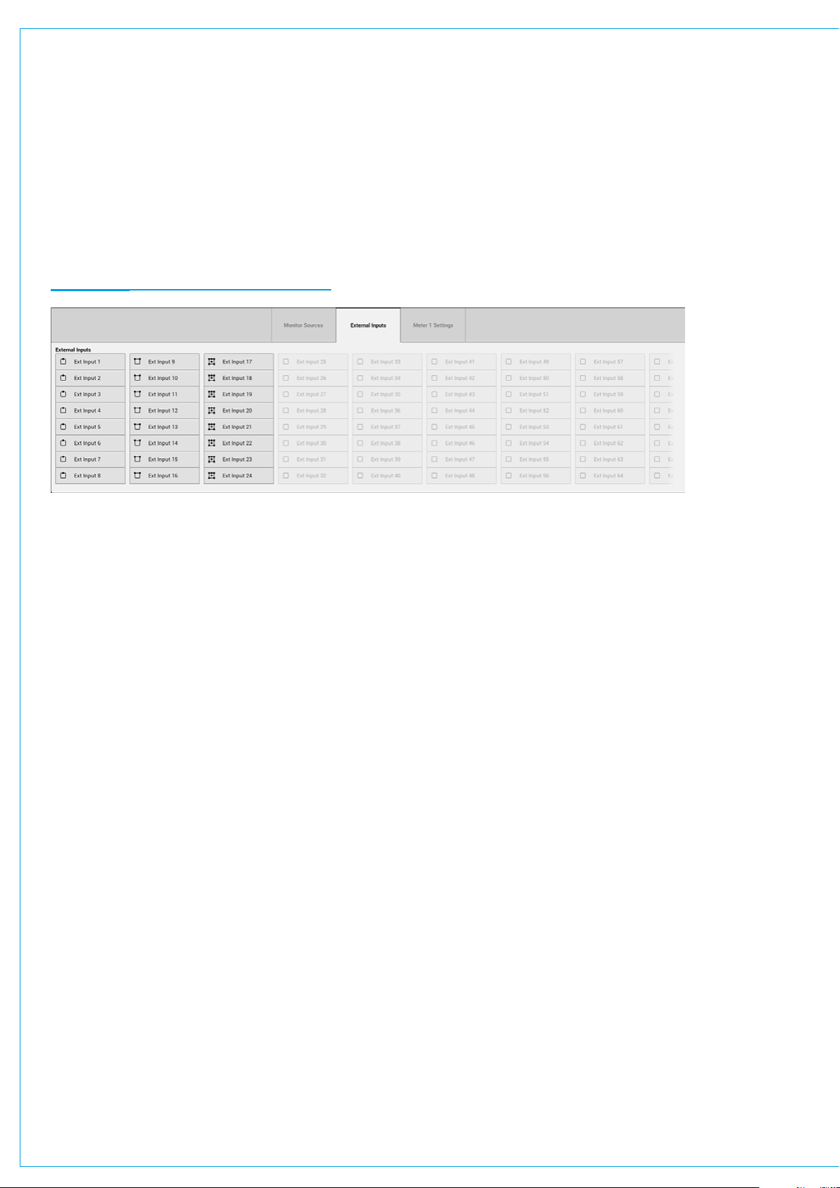
Metering External Inputs
To meter an external input:
1. Tap one of the four meter selectors to the bottom right of the touch display.
2. Select the external input tab within the pop-up.
3. Select the external input that you wish to meter.
Metering is explained in more detail here: “Meter Types” on page 117.
FIGURE 3 - METERING EXTERNAL INPUTS
96 SUMMA Networked Audio Production System GET TING SIGNALS IN AND OUT
Page 97

DIRECT OUTPUTS
Direct outputs are path specific desk outputs, which are available for patching. Summa has a pool of 188
resources, which can be assigned to be direct outputs or mix minus outputs.
Assigning a Direct Output
To assign a direct output to a path:
1. In ‘active Show’ view, tap the direct output routing tab.
2. Tap MONO, STEREO or 5.1 to choose a direct output width.
3. If not enough resources are available for the output that you want to create you can remove other direct / mix
minus outputs to free-up resources.
Note, within the pop-up the number of remaining direct / mix minus resources is displayed.
Removing a Direct Output
To remove a direct output:
1. Tap to choose NO PATH from the path width drop-down menu in the direct output control window header.
2. A pop-up will appear asking you to confirm the removal of the direct output, tap either REMOVE OUTPUT or
CANCEL .
Downmix/Spill
If a direct output is assigned to a surround path, two options appear to the bottom of the direct output window that
allow you to set whether the downmix or spill faders are used for downmixing the path to mono or stereo.
See “Downmixing” on page 167 for more information.
Direct Output Controls
• Tap the width drop-down menu to change the width of the direct output or select ‘no width’ to remove it.
• Tone: Tap to inject tone into the direct output, replacing the direct output feed with the correct tone for the width of
the path.
• Direct Output Patching: The direct output’s patch destination is displayed.
• Level: Turn the level rotary control to alter the level of the direct output between ‘off’ and +10 dB.
• Send Position: Direct outputs can be taken at different points in the associated path’s signal flow, pre EQ, pre fader
or post fader.
• Use Downmix Levels: If the direct output’s associated path is 5.1 and the direct output is stereo or mono you
can choose whether or not to use the downmix fader levels during the downmixing process.
• AFL: Tapping AFL replaces the console monitor source with the direct output feed, post level control, providing a
non-destructive solo for the direct output.
• Output Listen: Similar to AFL but the feed is taken post output delay.
• Talkback: Replaces the direct output feed with whatever is routed to the talkback input.
CALREC Putting Sound in the Picture 97
Page 98

FIGURE 1 - THE DIRECT OUTPUT WINDOW
98 SUMMA Networked Audio Production System GETTING SIGNALS IN AND OUT
Page 99

MIX MINUS OUTPUTS
Mix minus outputs are path- specific desk outputs, which are available for patching. Summa has a pool of 188
resources which can be assigned to be mix minus outputs or direct outputs.
Mix minus outputs are used to create foldback feeds using a comprehensive contribution system for defining the paths or
buses that feed the output. See “Mix Minus” on page 155 for detailed information on how to set up and use the mix minus
system, including a list of all mix minus controls.
Assigning a Mix Minus Output
To assign a mix minus output:
1. In ‘active Show’ view, tap the mix minus output routing tab.
2. Tap MONO or STEREO to select the mix minus output width that you wish to create for the currently accessed
path.
If not enough resources are available for the desired output, you can remove other direct/mix minus outputs to free-up
resources. Note, at the bottom of the pop-up the number of remaining resources is displayed.
Removing a Mix Minus Output
To remove a mix minus output:
1. Choose NO PATH from the path width drop-down menu in the mix minus control window header.
2. A pop-up will appear asking you to confirm the removal of the mix minus output. Tap either REMOVE OUTPUT
or CANCEL .
CALREC Putting Sound in the Picture 99
Page 100

BUS OUTPUTS
Summa’s bus outputs—4 mains, 16 auxs and 32 tracks—are all available for patching from the I/O patching screen.
Bus outputs appear under desk outputs in the sources window.
Multiple paths can be routed to each bus using the routing tabs down the right hand side of the control window.
See “Routing a Signal” on page 164 for more detailed information.
Mains
Mains are generally used as main broadcast outputs of the system as well as to feed monitoring systems.
Two versions of each main are available for patching out of the system: main and main (pre talkback and tone).
Main (pre talkback and tone) is generally used for monitoring output, for example, during rehearsals.
Tracks and Auxs
Tracks and Auxs are generally used to feed external signal processing devices or to create interruptable foldback feeds.
Auxs differ to tracks in that each path has individual level controls and send position switches for each of the 16 aux
feeds, allowing a high level of control over 16 separate mixes. Each path has one level control and position switch for all
32 track sends—auxs also have an additional level of logic control, allowing you to set conditions under which each pre
fader aux send should be cut.
See “Buses and Outputs” on page 162 for more detailed information on using and configuring buses.
100 SUMMA Networked Audio Production System GETTING SIGNALS IN AND OUT
 Loading...