

Calogic LLC CLM385T2, CLM385N2, CLM385-2.5, CLM285-2.5 Datasheet
CORPORATION
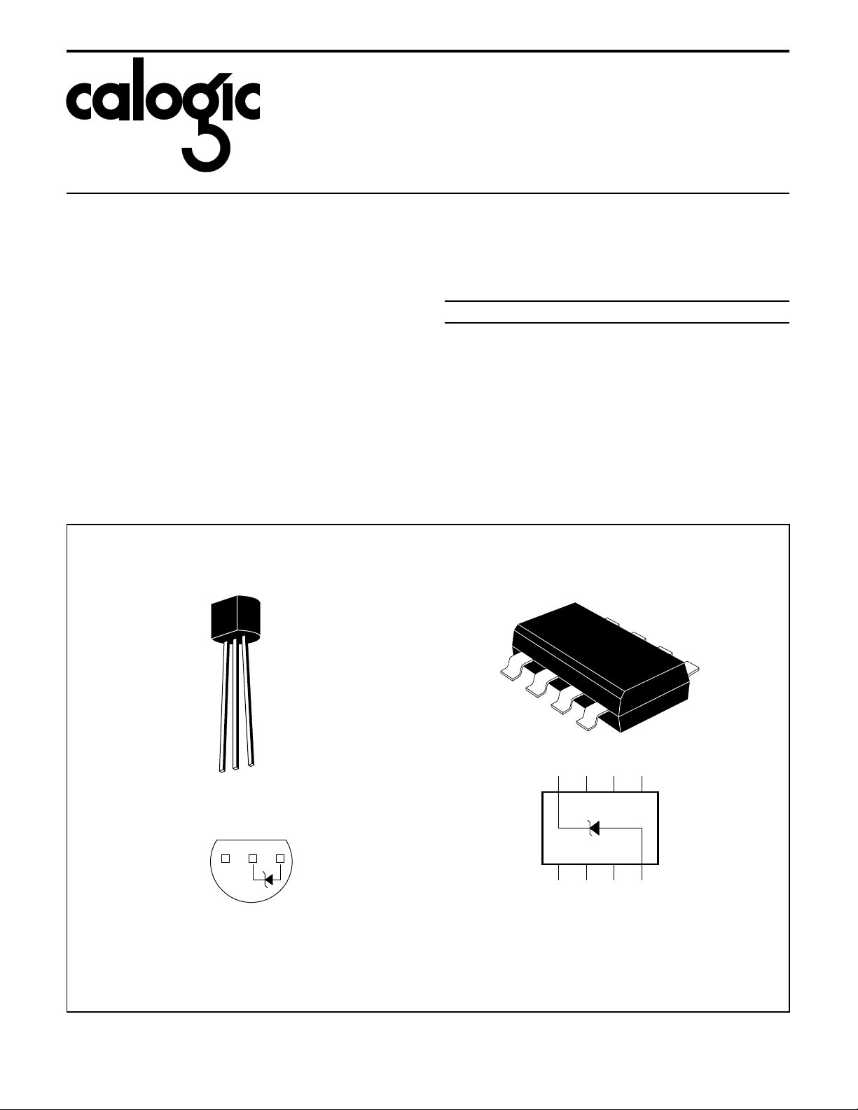
876 5
1 2 3 4
NC NC NC+
NC NC -NC
SO PACKAGE
(Y-SUFFIX)
BOTTOM VIEW
Micropower
Voltage Reference Diode
CLM285-2.5 / CLM385-2.5
FEATURES
Operating Current . . . . . . . . . . . . . . . . . . . 20µA - 20mA
••
Dynamic Impedance . . . . . . . . . . . . . . . . . . . . . . . . . . 1Ω
••
Low Voltage Reference . . . . . . . . . . . . . . . . . . . . . . . 2.5V
••
PRODUCT DESCRIPTION
The CLM285 / 385 - 2.5 are 2 terminal band-gap voltage
regulator diodes. Operating over a 20µA to 20mA current range.
The de vices p rovi de good tem perat ure s tabilit y and exceptionally
low dynamic i mpedance. Desi gned for appl ications i n portable
meters, regulators or general purpose cir cuitry.
PIN CONFIGU R ATIONS
TO-92
ORDERING INFORMATION
Part Package Max Temp co (p pm ) Temp Range
o
CLM285Y2 SOIC 100 -40
CLM385T2 TO-46 100 0
CLM385N2 TO -92 100 0
CLM385Y2 SOIC 100 0
SO-8
C to +85oC
o
C to +70oC
o
C to +70oC
o
C to +70oC
123
TO-92 (N-SUFFIX)
BOTTOM VIEW

CLM285-2.5 / CLM385-2.5
CORPORATION
ABSOLUTE MAXIMUM RATINGS (Note 1)
≤ 20mA
≤ 1mA
o
C to +150oC
Reverse Current . . . . . . . . . . . . . . . . . . . . . . . . . . . . . . 30mA
Forward Current. . . . . . . . . . . . . . . . . . . . . . . . . . . . . . . 10mA
Operating Temperatur e Range (Not e 3)
CLM185-2.5 . . . . . . . . . . . . . . . . . . . . . . . -55
CLM285-2.5 . . . . . . . . . . . . . . . . . . . . . . . . -40
CLM385-2.5 . . . . . . . . . . . . . . . . . . . . . . . . . . 0
o
C to +125oC
o
C to +85oC
o
C to +70oC
Storage Tempe ra tu re. . . . . . . . . . . . . . . . . . -55
Soldering Inform ation
TO-92 Package (10 sec.). . . . . . . . . . . . . . . . . . . . . 260
TO-46 Package (10 sec.). . . . . . . . . . . . . . . . . . . . . 300
SO Package: Vapor Phase (60 sec.) . . . . . . . . . . 215
Infrared (15 sec.) . . . . . . . . . . . . . . 220
ELECTRICAL CHARACTERISTIC S (Continued) (Note 3)
CLM285-2.5 CLM385-2.5
PARAMETER TYP
Reverse Breakdown
Voltage
2.5 2.460
TESTED
LIMIT
(NOTE 4)
2.535
DESIGN
LIMIT
(NOTE 5)
TESTED
LIMIT
(NOTE 4)
2.470
2.530
DESIGN
LIMIT
(NOTE 5)
Minimum Operating Current 13 18 20 20 20 µA(Max)
Reverse Breakdown Voltage
Change with Curre nt
1 1.5 2.0 1.5 mV(Max) 20µA ≤ I
10 20 20 25 mV(Max) 1mA ≤ I
Reverse Dynamic Impedance 1 Ω I
Wideband Noise (rms) 120 µV
Long Term
Stability
Average Temperature
Coefficient (Note 6)
20 ppm
50 100 100 ppm/
Note 1: Abso lut e Maxim u m Rating s indi cate limits beyon d which da mage to the device ma y oc cur. Operatin g Ratin gs indi ca te cond itio ns for
which the device is intended to be function al, but do not guaran te e specific performance limits. For guarante ed specif icatio ns and test conditions,
see the Electrical Characteristics. The guaranteed specifications apply only for the test conditions listed.
Note 2: For elevated temperature operation, T
CLM285 125
CLM385 100
Thermal Resistance TO-92 SO-8
θ
(Junction to Ambient)
ja
θ
(Junction to Case) N/A N/A
jc
o
C
o
C
o
C/W (0.4" Leads)
180
o
170
C/W (0.125" Leads)
max is :
j
165
o
C/W
Note 3: Parameters identified with boldface type apply at temperature extremes. All other numbers apply at TA = TJ = 25oC.
Note 4: Guaranteed and 100% production tested.
Note 5: Guaranteed, but not 100 % production tested. These limits are not used to calcula te average outg oing quality leve ls.
Note 6: The average temperature coefficient is defined as the maximum deviation of reference voltage at all measured temperatures between
the operating T
MAX
and T
, divided by T
MIN
MAX-TMIN
. The measured temperatures are -55oC, -40oC, 0oC, 25oC, 70oC, 85oC, 125oC.
UNITS
(LIMITS)
V(min)
V(max)
T
20µA ≤ I
R
I
R
10Hz ≤ f ≤ 10kHz
I
R
T
o
C(Max) IR = 100µA
CONDITIONS
= 25oC,
A
R
R
≤ 20mA
R
= 100µA, f = 20Hz
= 100µA
= 100µA, T = 1000Hr,
= 25oC ±.0.1oC
A
o
C
o
C
o
C
o
C
 Loading...