

California Instruments MX60-3Pi, MX60-3Pi-MB, MX90-3, MX90-3Pi, MX90-3Pi-MB User Manual
...Page 1

Revision AJ
CompuMess Elektronik GmbH • Lise-Meitner-Str. 1 • D-85716 Unterschleißheim
Telefon (089) 32 15 01- 0 • Telefax (089) 3215 01-11 • www.compumess.de • www.netzteile.de
September 2008
by California Instruments.
All rights reserved.
Copyright 2002-2008
P/N 7003-960
MX Series
AC and DC Power Source
User Manual
Series I / Series II
TEL: +1 (858) 677-9040
FAX: +1 (858) 677-0940
Email:
Web Site:
http://www.calinst.com
Page 2

User Manual – Rev AJ California Instruments
User's Manual
AC Power Source
California Instruments, an AMETEK Company.
Models:
MX30-1
MX30-3
MX30-3Pi
MX45-1
MX45-3
MX45-3Pi
MX60-3
MX60-3Pi (-MB)
MX90-3
MX90-3Pi (-MB)
MX135-3
MX135-3Pi (-MB)
MX180-3
MX180-3Pi (-MB)
MX225-3
MX225-3Pi (-MB)
MX270-3
MX270-3Pi (-MB)
Note: For MX15-1, MX15-1Pi, see user manual P/N 7005-960.
Copyright 2002 - 2008, California Instruments. Rev AJ, September 2008.
2 MX Series
Page 3

User Manual – Rev AJ California Instruments
SAFETY SUMMARY
This power source contains high voltage and current circuits, which are potentially lethal.
Because of its size and weight, mechanical stability must be ensured. The following safety
guidelines must be followed when operating or servicing this equipment. These guidelines
are not a substitute for vigilance and common sense. California Instruments assumes no
liability for the customer’s failure to comply with these requirements. If the power source is
used in a manner not specified by California Instruments, the protection provided by the
equipment may be impaired.
BEFORE APPLYING POWER
1. Verify the correct three phase input voltage is applied to the unit. Input ratings are shown on the
model and serial number tag located at the rear of the unit.
2. The chassis and cabinet of this power source must be grounded to minimize shock hazard. A
chassis ground is provided at the input terminal block. This is located in the front of the cabinet
on the lower left hand side. The lower front cover panel must be removed to access the line
input and ground connections. The chassis ground must be connected to an electrical ground
through an insulated wire of sufficient gauge.
FUSES
Use only fuses of the specified current, voltage, and protection speed (slow blow, normal blow, fast
blow) rating. Do not short out the fuse holder or use a repaired fuse.
DO NOT OPERATE IN A VOLATILE ATMOSPHERE
Do not operate the power source in the presence of flammable gases or fumes.
DO NOT TOUCH ENERGIZED CIRCUITS
Disconnect the power cable before servicing this equipment. Even with the power cable
disconnected, high voltage can still exist on some circuits. Discharge these voltages before servicing.
Only qualified service personnel may remove covers, replace components or make adjustments.
DO NOT SERVICE ALONE
Do not remove covers, replace components, or make adjustments unless another person, who can
administer first aid, is present.
DO NOT EXCEED INPUT RATINGS
Do not exceed the rated input voltage or frequency. Additional hazards may be introduced because of
component failure or improper operation.
DO NOT MODIFY INSTRUMENT OR SUBSTITUTE PARTS
Do not modify this instrument or substitute any parts. Additional hazards may be introduced because
of component failure or improper operation.
MOVING THE POWER SOURCE
When moving the power source, observe the following:
1. Remove all AC power to unit.
2. Don not attempt to lift by hand. Raise the levelers and push the unit using two people to prevent
injury or use forklift equipment with a qualified operator.
ALLOW CAPACITORS TO DISCHARGE
Capacitors in the power source may hold a hazardous electrical charge even if the power source has
been disconnected from the mains supply. Allow capacitors to discharge to a safe voltage before
servicing internal circuits or touching exposed pins of mains supply connectors.
MX Series 3
Page 4
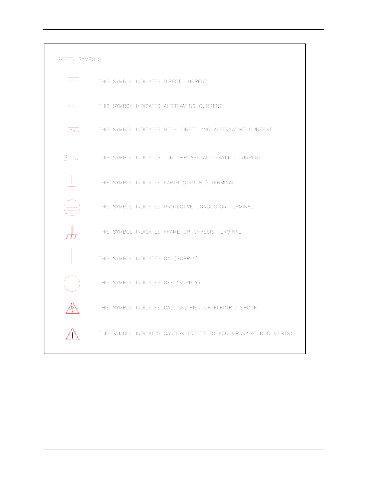
User Manual – Rev AJ California Instruments
4 MX Series
Page 5

User Manual – Rev AJ California Instruments
WARRANTY INFORMATION
CALIFORNIA INSTRUMENTS CORPORATION warrants each instrument manufactured by them to be free
from defects in material and workmanship for a period of one year from the date of shipment to the original
purchaser. Excepted from this warranty are fuses and batteries that carry the warranty of their original
manufacturer where applicable. CALIFORNIA INSTRUMENTS will service, replace, or adjust any defective
part or parts, free of charge, when the instrument is returned freight prepaid, and when examination reveals
that the fault has not occurred because of misuse, abnormal conditions of operation, user modification, or
attempted user repair. Equipment repaired beyond the effective date of warranty or when abnormal usage
has occurred will be charged at applicable rates. CALIFORNIA INSTRUMENTS will submit an estimate for
such charges before commencing repair, if so requested.
VOIDED WARRANTY
Any misuse or abuse of, as well as any modifications or changes made to any California Instruments
product will automatically void the factory warranty. Removing non-normal use related covers or any sealed
covers or lids also automatically voids factory warranty unless express written or email authorization is
obtained from the customer service department in advance. The customer service department can be
reached via email at
SERVICE PROCEDURE
If a fault develops, notify CALIFORNIA INSTRUMENTS at [email protected] or its local representative,
giving full details of the difficulty, including the model number and serial number. On receipt of this
information, service information or a Return Material Authorization (RMA) number will be given. Add the
RMA number furnished to the shipping label. Pack the instrument carefully to prevent transportation
damage, affix label to shipping container, and ship freight prepaid to the factory. CALIFORNIA
INSTRUMENTS shall not be responsible for repair of damage due to improper handling or packing.
Instruments returned without RMA No. or freight collect may be refused at California Instruments discretion.
Instruments repaired under Warranty will be returned either via prepaid surface freight or low cost airfreight
at California Instruments discretion. Instruments repaired outside the Warranty period will be returned
freight collect, Ex Works CALIFORNIA INSTRUMENTS 9689 Towne Centre Drive, San Diego, CA 92121-
1964. If requested, an estimate of repair charges will be made before work begins on repairs not covered
by the Warranty.
DAMAGE IN TRANSIT
The instrument should be tested when it is received. If it fails to operate properly, or is damaged in any
way, a claim should be filed immediately with the carrier. The claim agent should obtain a full report of the
damage, and a copy of this report should be forwarded to us by fax or email (Fax: 858 677 0940, Email:
[email protected]). CALIFORNIA INSTRUMENTS will prepare an estimate of repair cost and repair the
instrument when authorized by the claim agent. Please include model number and serial number when
referring to the instrument.
SPARE PARTS
To order spare parts, user manuals, or determine the correct replacement part for your California
Instruments products, please contact the Customer Service department by phone at + 1 858 677 9040,
press 2 or by email
MX Series 5
Page 6

User Manual – Rev AJ California Instruments
Table of Contents
1. Introduction................................................................................................................................... 11
1.1 General Description......................................................................................................................... 11
1.2 Manual organization and format ...................................................................................................... 11
1.3 Different Model Series..................................................................................................................... 12
2. Specifications ............................................................................................................................... 13
2.1 Electrical.......................................................................................................................................... 13
2.2 Mechanical ...................................................................................................................................... 22
2.3 Environmental ................................................................................................................................. 23
2.4 Regulatory....................................................................................................................................... 23
2.5 Front Panel Controls ....................................................................................................................... 23
2.6 Special Features and Options ......................................................................................................... 24
2.7 Supplemental Specifications ........................................................................................................... 31
3. Unpacking and Installation ........................................................................................................... 36
3.1 Unpacking ....................................................................................................................................... 36
3.2 Power Requirements....................................................................................................................... 36
3.3 Mechanical Installation .................................................................................................................... 37
3.4 AC Input Connections and Wiring ................................................................................................... 37
3.5 AC On/Off Circuit Breaker on MX Series front panel....................................................................... 40
3.6 Output Connections......................................................................................................................... 42
3.7 Connectors - Rear Panel................................................................................................................. 55
3.8 Multiple Cabinet System Configurations (incl. –MB)........................................................................ 63
3.9 Multiple Cabinet Power Up/Down Procedures................................................................................. 65
3.10 Clock and Lock Configurations........................................................................................................ 66
3.11 Basic Initial Functional Test............................................................................................................. 68
3.12 Remote Inhibit / Remote Shutdown................................................................................................. 70
3.13 Junction Box Accessory .................................................................................................................. 71
3.14 Output Filter Box Accessory............................................................................................................ 72
3.15 Fuse Box Accessory........................................................................................................................ 73
4. Front Panel Operation .................................................................................................................. 74
4.1 Tour of the Front Panel ................................................................................................................... 74
4.2 Menu Structure................................................................................................................................81
4.3 Output Programming ..................................................................................................................... 119
4.4 Waveform Management [3Pi Controller only]................................................................................ 121
4.5 Standard Measurements ............................................................................................................... 126
4.6 Advanced Measurements [3Pi Controller only].............................................................................. 128
4.7 Transient Programming................................................................................................................. 137
5. Principle of Operation ................................................................................................................. 144
5.1 General ......................................................................................................................................... 144
5.2 Overall Description ........................................................................................................................ 144
5.3 Controller Assembly ...................................................................................................................... 146
5.4 System Interface Board................................................................................................................. 150
5.5 Current / Voltage Sensor Board .................................................................................................... 150
5.6 Low Voltage Power Supply............................................................................................................ 150
5.7 Power Module ............................................................................................................................... 151
6. Calibration................................................................................................................................... 156
6.1 Recommended Calibration Equipment.......................................................................................... 156
6.2 Front Panel Calibration Screens.................................................................................................... 157
6.3 Routine Measurement Calibration ................................................................................................. 160
6.4 Routine Output Calibration ............................................................................................................ 164
6.5 Non-Routine Calibration ................................................................................................................ 171
6 MX Series
Page 7

User Manual – Rev AJ California Instruments
7. Service ........................................................................................................................................ 176
7.1 Cleaning.........................................................................................................................................176
7.2 General..........................................................................................................................................176
7.3 Basic operation ..............................................................................................................................176
7.4 Advanced Troubleshooting. ...........................................................................................................178
7.5 Factory Assistance ........................................................................................................................180
7.6 Fuses.............................................................................................................................................181
7.7 Firmware Updates .........................................................................................................................182
8. Top Assembly Replaceable Parts .............................................................................................. 185
9. Options........................................................................................................................................ 189
9.1 Introduction....................................................................................................................................189
9.2 Option -HV: Additional AC Voltage Range..................................................................................... 190
9.3 Option –160: RTCA/DO-160 Tests ................................................................................................191
9.4 Option –411: IEC 61000-4-11 Voltage Dips and Interruptions ....................................................... 205
9.5 Option –413: IEC 61000-4-13 Interharmonics Test .......................................................................213
9.6 Option –704: MilStd704 Tests........................................................................................................224
9.7 Option –ABD: Airbus ABD0100.1.8 Test .......................................................................................236
9.8 Option –AMD: Airbus AMD24C Test.............................................................................................. 236
9.9 Option –787: Boeing B787-0147 Test........................................................................................... 236
9.10 Option –WHM: Watt Hour Measurement .......................................................................................237
10. Error Messages .......................................................................................................................... 239
Index.................................................................................................................................................. 244
MX Series 7
Page 8

User Manual – Rev AJ California Instruments
List of Figures
Figure 2-1: MX30-3 Voltage / Current Rating Chart for 150/300 V AC Ranges......................................................................... 16
Figure 2-2: MX45-3 Voltage / Current Rating Chart for 150/300 V AC Ranges – Max Rating.................................................... 17
Figure 2-3: Voltage / Current Rating Chart for 150/300 V AC Ranges – Derated....................................................................... 17
Figure 2-4: MX30-3 Voltage / Current Rating Chart for 200/400 V DC Ranges.......................................................................... 18
Figure 2-5: MX45-3 Voltage / Current Rating Chart for 200/400 V DC Ranges – Max. Rating ..................................................18
Figure 2-7: MX30-3 Voltage / Current Rating Chart, -HV Option............................................................................................... 27
Figure 2-8: MX45-3 Voltage / Current Rating Chart, -HV Option – Max. Rating......................................................................... 27
Figure 2-9: Voltage / Current Rating Chart, -HV Option – Derated............................................................................................. 27
Figure 2-10: -HF Option Voltage Frequency Rating 300V range................................................................................................ 29
Figure 2-11: -HF Option Voltage Frequency Rating 150V range................................................................................................ 29
Figure 2-12: MX output filter option schematic ...........................................................................................................................33
Figure 2-13: MX45 Output Noise 10 KHz – 1 MHz ..................................................................................................................... 34
Figure 2-14: MX45 Output Noise 10 KHz - 1 MHz with optional Filter........................................................................................35
Figure 3-1: The MX45 Power Source..........................................................................................................................................36
Figure 3-2: Location of AC Input Fuse Block and Chassis Ground Connection - Front View, Access Panel Removed............ 38
Figure 3-3: MX Series AC Input Connection Diagram (Rear view).............................................................................................39
Figure 3-4: Rear Panel................................................................................................................................................................ 41
Figure 3-5: External sense cable shield connection to chassis ground ...................................................................................... 42
Figure 3-6: Location of Output Terminals (Front view)................................................................................................................44
Figure 3-7: MX30-1 / MX45-1 Output Wiring (Rear view) ........................................................................................................... 45
Figure 3-8: MX30-3 / MX45-3 Output Wiring (Rear view) ........................................................................................................... 46
Figure 3-9:MX60, MX60-MB, MX90 or MX90-MB Output Wiring (Rear view) ............................................................................47
Figure 3-10: Two MX's in Clock and Lock mode Output Wiring (Rear view) .............................................................................. 48
Figure 3-11: MX135 or MX135-MB Output Wiring (Rear view)................................................................................................... 50
Figure 3-12: Three MX's in Clock and Lock mode - Output Wiring (Rear view) .........................................................................51
Figure 3-13: MX180, MX225 or MX270 Output Wiring (Rear view)...........................................................................................53
Figure 3-14: Ship kit Terminal Block dimensions........................................................................................................................ 54
Figure 3-15: RS232C Cable for PC Connection wiring diagram – MX without USB................................................................... 59
Figure 3-16: USB Connector pin orientation. .............................................................................................................................. 60
Figure 3-17: Emergency Switch (ES Option) shut off inter connect on -MB systems.................................................................62
Figure 3-18: Multi-Cabinet DIP Switch Location and Setting ...................................................................................................... 64
Figure 3-19: Functional Test Setup............................................................................................................................................. 69
Figure 3-20: 7003-416-1 Output Junction Box............................................................................................................................71
Figure 3-21: 7003-424-1 Output noise filter box. ........................................................................................................................72
Figure 3-22: 7003-426-1 Output Fuse Box .................................................................................................................................73
Figure 4-1: Shuttle Knob ............................................................................................................................................................. 76
Figure 4-2: FUNCTION Keypad.................................................................................................................................................77
Figure 4-3: Entering Values from the Decimal Keypad...............................................................................................................79
Figure 4-4: Cursor UP Key Movement........................................................................................................................................79
Figure 4-5: Cursor DOWN key Movement .................................................................................................................................. 80
Figure 4-6: Main Menu 1 Screen ................................................................................................................................................80
Figure 4-7: Menu 1 through 3......................................................................................................................................................81
Figure 4-8: PROGRAM Menu ..................................................................................................................................................... 85
Figure 4-9: MEASUREMENTS Screen, Single Phase and Three Phase Modes .......................................................................87
Figure 4-10: HARMONICS/TRACE ANALYSIS Screen..............................................................................................................89
Figure 4-11: TRANSIENTS Menu...............................................................................................................................................92
Figure 4-12: VOLTAGE SURGE/SAG SETUP Screen...............................................................................................................93
Figure 4-13: VOLTAGE SWEEP/STEP SETUP Screen.............................................................................................................95
Figure 4-14: FREQUENCY SWEEP/STEP SETUP Screen .......................................................................................................97
Figure 4-15 VOLTAGE/FREQUENCY SWEEP/STEP SETUP Screen .....................................................................................98
Figure 4-16:START/VIEW TRANSIENT SEQUENCE Screen.................................................................................................... 99
Figure 4-17: WAVEFORMS Menu ............................................................................................................................................ 100
Figure 4-18: APPLICATIONS Menu..........................................................................................................................................103
Figure 4-19: SETUP REGISTERS Menu..................................................................................................................................104
Figure 4-20: UTILITY Menu ......................................................................................................................................................105
Figure 4-21: GPIB/RS232 SETUP Menu .................................................................................................................................. 108
Figure 4-22: VOLTAGE/CURRENT CONTROL SETUP Menu................................................................................................. 109
Figure 4-23: INITIAL SETUP Menus......................................................................................................................................... 111
Figure 4-24: LIMIT SETUP Menu..............................................................................................................................................113
Figure 4-25: CONFIGURATION SETUP Menus....................................................................................................................... 114
Figure 4-26: OUTPUT IMPEDANCE Menu............................................................................................................................... 116
Figure 4-27: MEASUREMENT CAL FACTORS Menu (Series I only) ......................................................................................117
Figure 4-28: MEASUREMENT CAL FACTORS Menu (Series II only) .....................................................................................117
Figure 4-29: OUTPUT CAL FACTORS Menu (Series I only).................................................................................................... 118
Figure 4-30: OUTPUT CAL FACTORS Menu (Series II only)................................................................................................... 118
Figure 4-31: Selecting a Waveform ..........................................................................................................................................121
Figure 4-32: Selecting Waveforms for Single Phase or All Phases .......................................................................................... 121
8 MX Series
Page 9

User Manual – Rev AJ California Instruments
Figure 4-33: Custom Waveform Creation with GUI Program ....................................................................................................122
Figure 4-34: Waveform Crest Factor Affects Max. rms Voltage................................................................................................124
Figure 4-35: Waveform Frequency Domain View Mode ...........................................................................................................125
Figure 4-36: Scrolling Through Tabular FFT Data ....................................................................................................................129
Figure 4-37: Scrolling through bar chart FFT Data....................................................................................................................129
Figure 4-38: Scrolling Through Acquired Waveform Data.........................................................................................................131
Figure 4-39: SET VOLT Trigger Source Acquisition .................................................................................................................133
Figure 4-40: Positive Trigger Delay (Post Trigger Data) ...........................................................................................................135
Figure 4-41: Negative Trigger Delay (Pre-Trigger Data) ...........................................................................................................136
Figure 4-42: Pulse Transients ...................................................................................................................................................138
Figure 4-43: List Transients.......................................................................................................................................................139
Figure 4-44: Switching Waveforms in a Transient List..............................................................................................................142
Figure 4-45: START/VIEW TRANSIENT SEQUENCE Menu ...................................................................................................143
Figure 5-1: MX Series Functional Block Diagram .....................................................................................................................144
Figure 5-2: MX Series Detailed Block Diagram.........................................................................................................................148
Figure 5-3: Power Module Detailed Block Diagram ..................................................................................................................149
Figure 5-4: Power Module Layout .............................................................................................................................................151
Figure 5-5: Amplifier Board Layout............................................................................................................................................153
Figure 6-1: Calibration Setup MX45-1 (Rear view) ...................................................................................................................158
Figure 6-2: Calibration Setup MX30-3Pi, MX45-3Pi or MX30-3, MX45-3 (Rear view)..............................................................159
Figure 6-3: Current Measurement Calibration Setup (Rear view) .............................................................................................160
Figure 6-4: DC offset AC filter ...................................................................................................................................................164
Figure 6-5: -413 Option Aux Generator Adjustments ................................................................................................................169
Figure 9-1: Application Menu ....................................................................................................................................................192
Figure 9-2: DO160 Main Menu..................................................................................................................................................193
Figure 9-3: Normal State...........................................................................................................................................................193
Figure 9-4: Voltage Modulation .................................................................................................................................................195
Figure 9-5: Frequency Modulation ............................................................................................................................................196
Figure 9-6: Power Interrupt .......................................................................................................................................................197
Figure 9-7: Power Interrupt for Group 2 and 3 ..........................................................................................................................198
Figure 9-8: Emergency Screen .................................................................................................................................................199
Figure 9-9: Abnormal Screen ....................................................................................................................................................200
Figure 9-10: DO-160 DC Main Menu ........................................................................................................................................202
Figure 9-11: Normal State.........................................................................................................................................................202
Figure 9-12: Abnormal State .....................................................................................................................................................203
Figure 9-13: Application Menu ..................................................................................................................................................207
Figure 9-14: IEC1000-4-11 Menu..............................................................................................................................................207
Figure 9-15: IEC Dips and Interrupts.........................................................................................................................................208
Figure 9-16: Voltage Variation Screen ......................................................................................................................................210
Figure 9-17: EN 61000-4-11 Voltage Variation specification- Edition 1.0 .................................................................................211
Figure 9-18: EN 61000-4-11 Voltage Variation specification- Edition 2.0 .................................................................................211
Figure 9-19: IEC 61000-4-11 GUI screen. ................................................................................................................................212
Figure 9-20: Application Setup Menus ......................................................................................................................................214
Figure 9-21: IEC1000-4-13 Menu..............................................................................................................................................214
Figure 9-22: IEC 1000-4-13 FCURVE.......................................................................................................................................216
Figure 9-23: IEC 1000-4-13 OSWING.......................................................................................................................................216
Figure 9-24: IEC 1000-4-13 SWEEP.........................................................................................................................................217
Figure 9-25: IEC 1000-4-13 Harmonics ....................................................................................................................................217
Figure 9-26: IEC 1000-4-13 INTERHARMONICS.....................................................................................................................218
Figure 9-27: IEC 61000-4-13 Meister Curve .............................................................................................................................218
Figure 9-28: IEC 61000-4-13 Test Flowchart Class 1 and 2.....................................................................................................220
Figure 9-29:IEC 61000-4-13 Test Flowchart Class 3................................................................................................................221
Figure 9-30: MENU 2 SCREEN ................................................................................................................................................223
Figure 9-31: INTERHARMONICS SCREEN .............................................................................................................................223
Figure 9-32: Application Menu ..................................................................................................................................................226
Figure 9-33: MIL704 Menu........................................................................................................................................................227
Figure 9-34: Steady State Menu ...............................................................................................................................................227
Figure 9-35: Transient Menu.....................................................................................................................................................229
Figure 9-36: Emergency Menu..................................................................................................................................................230
Figure 9-37: Abnormal Screen ..................................................................................................................................................231
Figure 9-38: MIL704 DC Menu..................................................................................................................................................232
Figure 9-39: Steady State DC ...................................................................................................................................................232
Figure 9-40: Transient Menu.....................................................................................................................................................233
Figure 9-41: Abnormal Test Screen ..........................................................................................................................................234
Figure 9-42: Emergency Test....................................................................................................................................................235
Figure 9-43: Application Screen................................................................................................................................................237
Figure 9-44: Watt-Hour Meter Screen .......................................................................................................................................237
Figure 9-45: WH-Meter Screen with Function Active ................................................................................................................237
MX Series 9
Page 10

User Manual – Rev AJ California Instruments
List of Tables
Table 3-1: Suggested Input Wiring Sizes for each MX Cabinet * ...............................................................................................40
Table 3-2: Suggested Output Wiring Sizes * ..............................................................................................................................43
Table 3-3: Output Terminal connections.....................................................................................................................................44
Table 3-4: System Interface Connectors.....................................................................................................................................56
Table 3-5: Analog Interface Connector ....................................................................................................................................... 56
Table 3-6: BNC Connectors........................................................................................................................................................57
Table 3-7: BNC Connectors........................................................................................................................................................57
Table 3-8: External Sense Connector.........................................................................................................................................57
Table 3-9: RS232 Connector pin out – MX with RS232 and USB. .............................................................................................58
Table 3-10: RS232C Connector pin out – MX with RS232 but no USB...................................................................................... 58
Table 3-11: USB Connector pin out. ........................................................................................................................................... 60
Table 3-12: RJ45 LAN Connector pin out. .................................................................................................................................. 61
Table 3-13: Clock and Lock Configuration settings ....................................................................................................................66
Table 3-14: Clock and Lock Initialization settings....................................................................................................................... 67
Table 3-15: Remote Inhibit Mode Settings.................................................................................................................................. 70
Table 6-1: Calibration Load Values........................................................................................................................................... 161
Table 6-2: Measurement Calibration Table............................................................................................................................... 163
Table 6-3: Output Calibration Table – MX Series I ...................................................................................................................170
Table 6-4: Output Calibration Table – MX Series II ..................................................................................................................170
Table 6-5: Current Limit Calibration .......................................................................................................................................... 173
Table 6-6: Programmable Z adjustment pots............................................................................................................................ 175
Table 6-7: Formulas to calculate R and L ................................................................................................................................. 175
Table 7-1: Basic Symptoms ...................................................................................................................................................... 176
Table 7-2: MX Fuse Ratings .....................................................................................................................................................181
Table 7-3: Flash Down load Messages..................................................................................................................................... 184
Table 8-1: Replaceable Parts ...................................................................................................................................................187
Table 8-2: Fuses ....................................................................................................................................................................... 188
Table 9-1: Normal Voltage and Frequency Minimum...............................................................................................................194
Table 9-2: Normal Voltage and Frequency Maximum...............................................................................................................194
Table 9-3: Normal Voltage Unbalance......................................................................................................................................194
Table 9-4: Normal VoltageSurge Sequence .............................................................................................................................198
Table 9-5: Normal Frequency Transient Sequence .................................................................................................................. 199
Table 9-6: Normal Frequency Variation Sequence...................................................................................................................199
Table 9-7: Emergency Voltage and Frequency Minimum.........................................................................................................200
Table 9-8: Emergency Voltage and Frequency Maximum........................................................................................................200
Table 9-9: Emergency Voltage Unbalance ............................................................................................................................... 200
Table 9-10: Abnormal Voltage Minimum................................................................................................................................... 201
Table 9-11: Abnormal Voltage Maximum.................................................................................................................................. 201
Table 9-12: Abnormal Frequency Transient..............................................................................................................................201
Table 9-13: Normal Voltage Minimum ......................................................................................................................................202
Table 9-14: Normal Voltage Maximum .....................................................................................................................................203
Table 9-15: Voltage Surge ........................................................................................................................................................ 203
Table 9-16: Abnormal Voltage Surge........................................................................................................................................ 204
Table 9-17: Phase mapping......................................................................................................................................................206
Table 9-18: IEC 61000-3-34 Table C.2.....................................................................................................................................206
Table 9-19: Dips and Interruptions Tests Performed During RUN ALL ...................................................................................208
Table 9-20: Voltage Variations Test Performed During RUN ALL ............................................................................................ 210
Table 10-1: Error Messages .....................................................................................................................................................243
10 MX Series
Page 11

User Manual – Rev AJ California Instruments
1. Introduction
This instruction manual contains information on the installation, operation, calibration and
maintenance of all power systems that use the MX Series power sources with the
programmable controller.
1.1 General Description
The MX Series AC and DC power source systems are high efficiency, floor standing AC and DC
power sources that provide a precise output with low distortion. Available voltage ranges are
150 Vac, 300 Vac and 400 Vac in AC mode and 200 Vdc and 400 Vdc in DC mode. The MX303Pi and MX45-3Pi can operate in either single or three-phase mode. The MX30 and MX45 is
also available in just single or three-phase mode. All other models always operate in threephase mode.
Models with a -1 or -3 designation provide full front panel operation but do not include certain
features such as arbitrary waveform generation unless added as an option at the time of order.
Models with the Pi controller offer several additional standard features, including the RS232C,
USB, LAN (option) and IEEE-488 interfaces, arbitrary waveform generation, dual voltage ranges
and additional measurement functions.
The MX Series units are contained in a compact floor standing enclosure on casters. This allows
the units to be moved around more easily.
Read the installation instructions carefully before attempting to install and operate the MX Series
power systems.
1.2 Manual organization and format
All user documentation for California Instruments power sources is provided on CDROM in
electronic format. (Adobe Portable Document Format) The required Adobe PDF viewer is
supplied on the same CDROM. This manual may be printed for personal use if a hardcopy is
desired. To request a hardcopy from California Instruments, contact customer service at
[email protected]. There will be an additional charge for printed manuals.
This manual contains sections on installation, normal use, maintenance and calibration. If the
MX system is equipped with a GPIB, RS232C, USB or LAN interface, refer to the MX
Programming manual for information on using the remote control interfaces and command
syntax. The programming manual is provided on the same CDROM as this user manual.
MX Series 11
Page 12

User Manual – Rev AJ California Instruments
1.3 Different Model Series
There are two versions of the MX Series product, Series I and Series II. This user manual
covers both MX model series with top level assembly part numbers 7003-400 (Series I) and
7003-422 (Series II). The difference between the Series I and the Series II is the controller used.
The Series II uses a newer controller design but retains backward compatibility with the Series I
products. The part number is shown on the model / serial number tag on the back of the MX
series. All Series II will have a firmware revision of 4.0 or higher. The firmware revision is
displayed briefly at power up on the LCD display and can also be queried over the bus by using
the *IDN? command.
Differences between the two model series are restricted to:
Reduced number of measurement calibration coefficients on Series II.
Increased measurement sampling rate on Series II.
Maximum DC offset range in AC+DC mode is 250Vdc on Series I, 220Vdc on Series II
Where relevant, differences are highlighted throughout the user manual.
12 MX Series
Page 13
User Manual – Rev AJ California Instruments
2. Specifications
Specifications shown are valid over an ambient temperature range of 25 5 C and apply after a
30 minute warm-up time. Unless otherwise noted, all specifications are per phase for sine wave
output into a resistive load. For three phase configurations or mode of operation, all
specifications are for Line to Neutral (L-N) and phase angle specifications are valid under
balanced load conditions only.
Note: Specifications for input and output current and power on MX180, MX225 and MX270
configurations are 4, 5 and 6 times those of MX45-3 and are not separately listed.
2.1 Electrical
2.1.1 Input
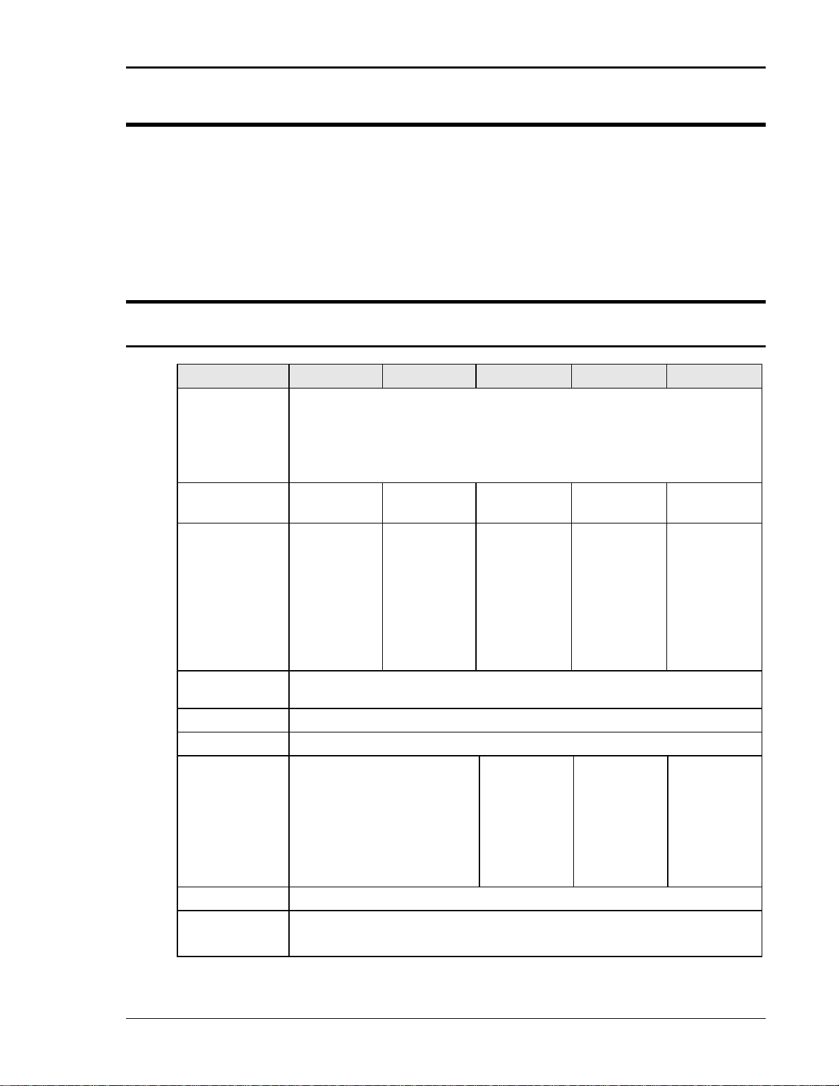
Parameter MX30 MX45 MX60 MX90 MX135
Line Voltage:
(3 phase, 3
wire + ground
(PE))
208 V
230 V
400 V
480 V
10%
LL
10%
LL
10%
LL
10%
LL
Line VA: 37 KVA 53 KVA 74 KVA 106 KVA 159 KVA
Line Current: 116 A
187 V
105 A
207 V
60 A
360 V
50 A
432 V
Line
47-63 Hz
RMS
RMS
RMS
RMS
@
LL
@
LL
@
LL
@
LL
175 A
187 V
157 A
207 V
90 A
360 V
75 A
432 V
RMS
RMS
RMS
RMS
@
LL
@
LL
@
LL
@
LL
Each MX30
chassis
requires its
own AC
service.
Total Line
currents are
2 x MX30
Each MX45
chassis
requires its
own AC
service.
Total Line
currents are
2 x MX45
Each MX45
chassis
requires its
own AC
service.
Total Line
currents are
3 x MX45
Frequency:
Efficiency: 85 % (typical) depending on line and load
Power Factor: 0.95 (typical) / 0.99 at full power.
Inrush Current: 230 Apk @ 208 V
220Apk @ 230 V
132Apk @ 400 V
110Apk @ 480 V
LL
LL
LL
LL
Each MX30
chassis
requires its
own AC
service.
Total Peak
currents are
2 x MX30
Each MX45
chassis
requires its
own AC
service.
Total Peak
currents are
2 x MX45
Each MX45
chassis
requires its
own AC
service.
Total Peak
currents are
3 x MX45
Hold-Up Time: > 10 ms
Isolation
Voltage:
2200 VAC input to output
1350 VAC input to chassis
MX Series 13
Page 14
User Manual – Rev AJ California Instruments
2.1.2 Output
Note: All specifications are for AC and DC unless otherwise indicated.
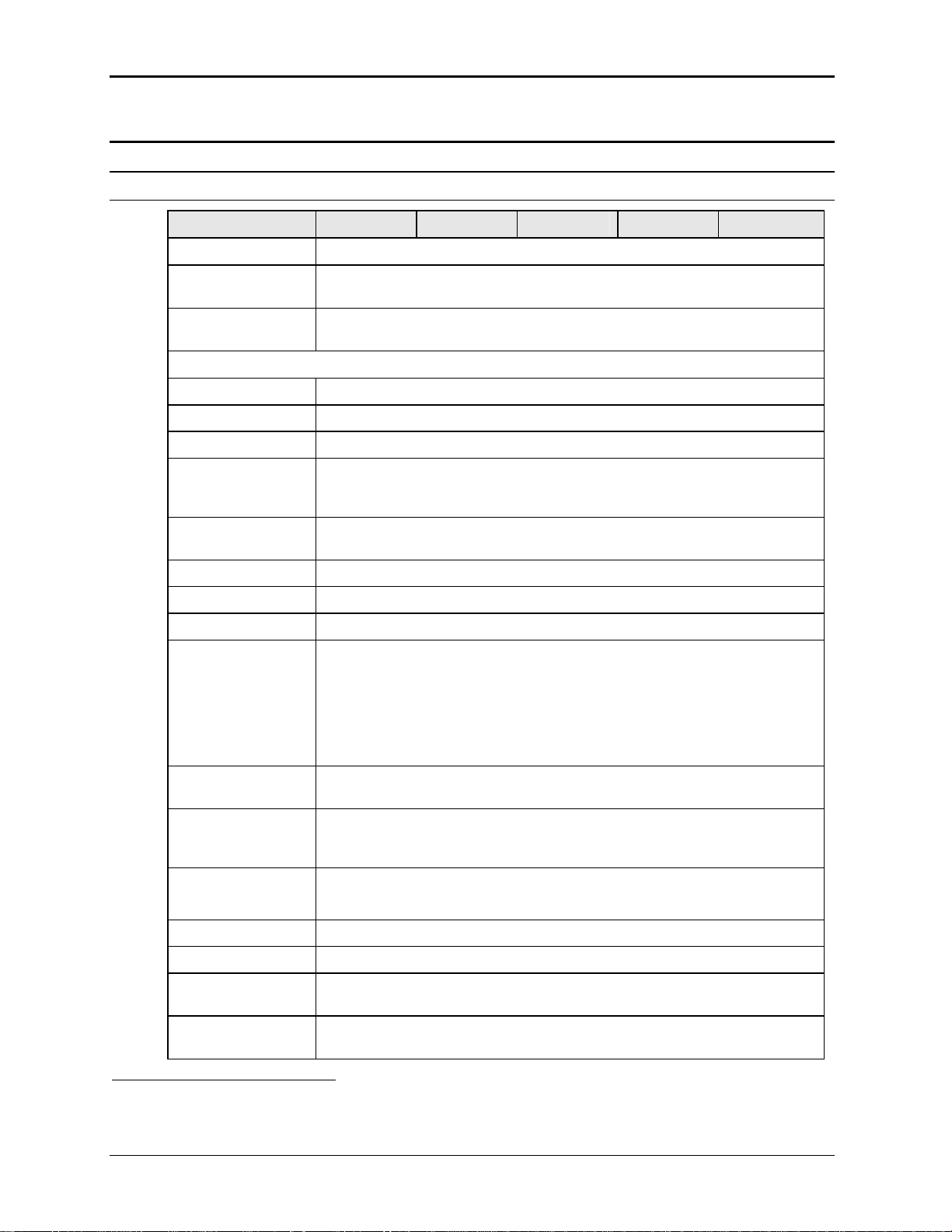
Output Parameter MX30 MX45 MX60 MX90 MX135
Modes
Std
AC, DC
Controller
Pi
AC, DC, AC+DC
Controller
Voltage:
Ranges (L-N):
AC Mode Low: 0 - 150 V / High: 0 - 300 V
DC Mode Low: 0 - 200 V / High: 0 - 400 V
AC+DC Mode AC: Low: 0 - 150 V / High: 0 - 300 V
DC Offset: Low Vrange: 0 - 150 V
High Vrange: 0 - 220 V (Series II) / High; 0 – 250 V (Series I).
Note:
On MX units with standard controller, only one voltage range is available unless
the -R range change option is installed.
Resolution:
AC Mode 0.1 V
DC Mode 0.1 V
AC+DC Mode AC: 0.1 V
DC Offset:
Series I 0.01 V < 2.5 V
0.1 V 2.5 - 25 V
1 V > 25 V
Series II 0.01 V
Accuracy: ± 0.3 V AC mode
± 1 V DC mode
Distortion THD1:
(Resistive full load)
< 1 % @ 16 - 66 Hz
< 2 % @ 66 - 500 Hz
< 3 % @ > 500 Hz
Load Regulation: 0.25 % FS @ DC - 100 Hz
0.5 % FS @ > 100 Hz
Line Regulation: 0.1% for 10% input line change
DC Offset Voltage: < 20 mV
Output Noise:
(20 kHz to 1 MHz)
< 2 V
< 3 V
low V Range
RMS
high V Range
RMS
Output Coupling DC coupled
Except on optional -HV or -XV Voltage range output, which is AC coupled.
1
The distortion specification for the MX Series is valid for pure (inductance < 12 uH) resistive load conditions and
using a 30 KHz LP filter on distortion meter.
14 MX Series
Page 15
User Manual – Rev AJ California Instruments
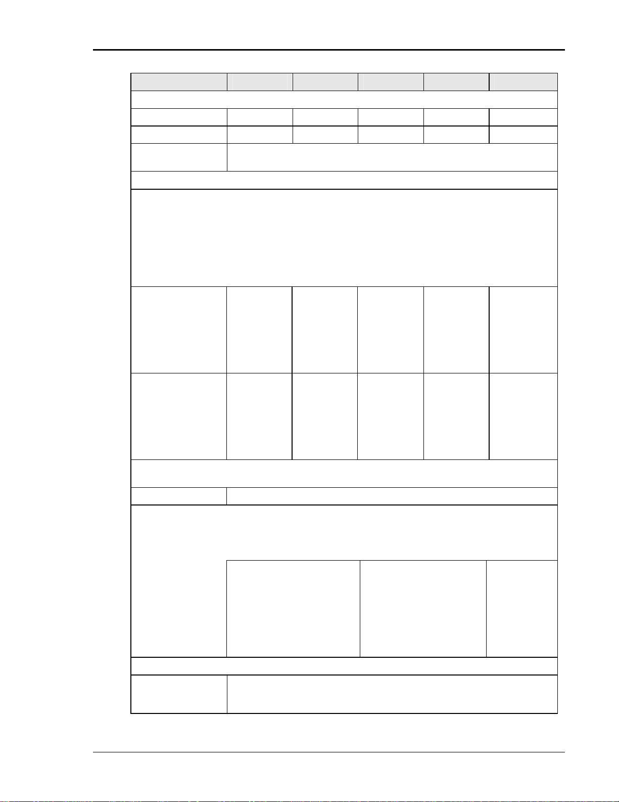
Output Parameter MX30 MX45 MX60 MX90 MX135
Power (total power for all phases, either range, at full scale voltage, maximum ambient T = 35° C)
AC Mode 30 KVA 45 KVA 60 KVA 90 KVA 135 KVA
DC Mode 20 KW 30 KW 40 KW 60 KW 90 KW
AC+DC Mode The maximum power and current in the AC+DC mode is equal to that in the DC
mode
Current
Note: Current, maximum amps indicated per phase available between 50 and 100 % of voltage
range. Maximum ambient temperate for full power operation at full-scale voltage is 35° C.
Constant Power Mode:
Operation at higher currents but constant power is possible from 80% of Voltage range
(125% of max. current) declining to 100% of maximum current at 100 % of voltage range
for short periods of time or at reduced ambient temperatures. (< 15 mins @ 30° C). See
Figure 2-3 and Figure 2-4. (Requires firmware revision 0.27 or higher.)
For MX30-3Pi model, constant power mode is supported at max ambient temperature.
AC Mode MX30-1
V Lo: 200 A
V Hi: 100 A
MX30-3, per
phase
V Lo: 66.7 A
V Hi: 33.3 A
DC Mode
AC+DC Mode
Note: Current derates linearly from 50% of voltage range to 20% of specified current at 5% of
voltage range
Current Limit mode Programmable, CC or CV mode
Repetitive Peak Current
Note: Maximum Peak Current shown. Value shown reflects absolute peak current protection level.
This level may not be reached under all load conditions. Depending on load conditions, peak current
may max out at lower levels due to amplifier output impedance.
AC Mode MX30-1 / MX30-3Pi 1Phs /
MX30-1
V Lo: 100 A
V Hi: 50 A
MX30-3, per
phase
V Lo: 33.3 A
V Hi: 16.7 A
MX45-1 / MX45-3Pi 1Phs
V Lo: 900 A
V Hi: 450 A
MX30-3 / MX30-3Pi / MX45-3
/ MX45-3Pi, per phase
V Lo: 300 A
V Hi: 150 A
MX45-1
V Lo: 300 A
V Hi: 150 A
MX45-3, per
phase
V Lo: 100 A
V Hi: 50 A
MX45-1
V Lo: 150 A
V Hi: 75 A
MX45-3, per
phase
V Lo: 50 A
V Hi: 25 A
MX60-3, per
phase
V Lo: 133 A
V Hi: 66.7 A
MX60-3, per
phase
V Lo: 66.7 A
V Hi: 33.3 A
MX60-3 / MX90-3, per
phase
V Lo: 600 A
V Hi: 300 A
MX90-3, per
phase
V Lo: 200 A
V Hi: 100 A
MX90-3, per
phase
V Lo: 100 A
V Hi: 50 A
MX135-3, per
phase
V Lo: 300 A
V Hi: 150 A
MX135-3, per
phase
V Lo: 150 A
V Hi: 75 A
MX135-3, per
phase
V Lo: 900 A
V Hi: 450 A
Frequency
Range: Standard: 16 Hz - 819.0 Hz (for –HV option range, 45 Hz – 819.0 Hz)
-LF option: 16 Hz - 500.0 Hz
-HF option: 16 Hz – 905 Hz
MX Series 15
Page 16
User Manual – Rev AJ California Instruments
Output Parameter MX30 MX45 MX60 MX90 MX135
Resolution: 0.01 Hz from 16.00 to 81.91 Hz
0.1 Hz from 82.0 to 819.0 Hz
Accuracy: ± 0.01 %
Phase (3 phase mode)
Range: Phase B/C relative to phase A
0.0 to 360.0°
Resolution: 0.1°
Accuracy: 16 Hz - 100 Hz: < 1.5°
100 Hz - 500 Hz: < 2°
> 500 Hz: < 4°
Ext. Sync Mode
Input: Isolated TTL input for external frequency control. Requires 5V at 5 mA for logic
high.
Accuracy: Ext. Sync to phase A with fixed Ext. Sync Frequency input:
16 Hz - 100 Hz: < 2°
100 Hz - 500 Hz: < 3°
> 500 Hz: < 4°
Programmable Output Impedance (available on MX30-3Pi and MX45-3Pi in three phase mode only)
Range: R: 1 – 200 mOhm
L: 15 – 200 uH
Resolution: R: 1 mOhm
L: 1 uH
Accuracy: 10 % FS N/A N/A N/A
N/A N/A N/A
N/A N/A N/A
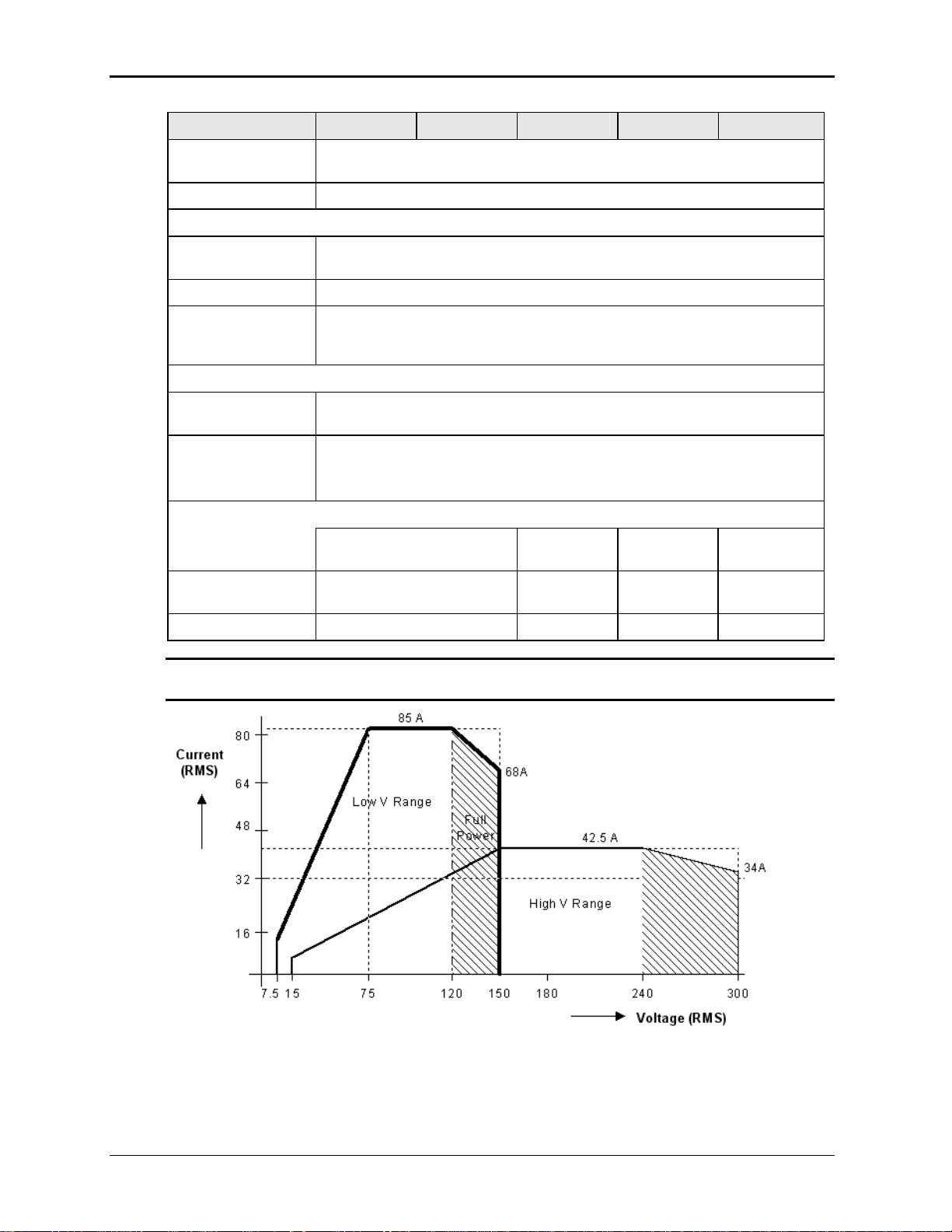
Note: Output specifications apply below the Current / Voltage rating lines shown in the
V/I rating chart below.
Figure 2-1: MX30-3 Voltage / Current Rating Chart for 150/300 V AC Ranges.
16 MX Series
Page 17
User Manual – Rev AJ California Instruments
100 A
100
Current
(RMS)
80
Low V Range
60
50 A
40
High V Range
20
7.5
15
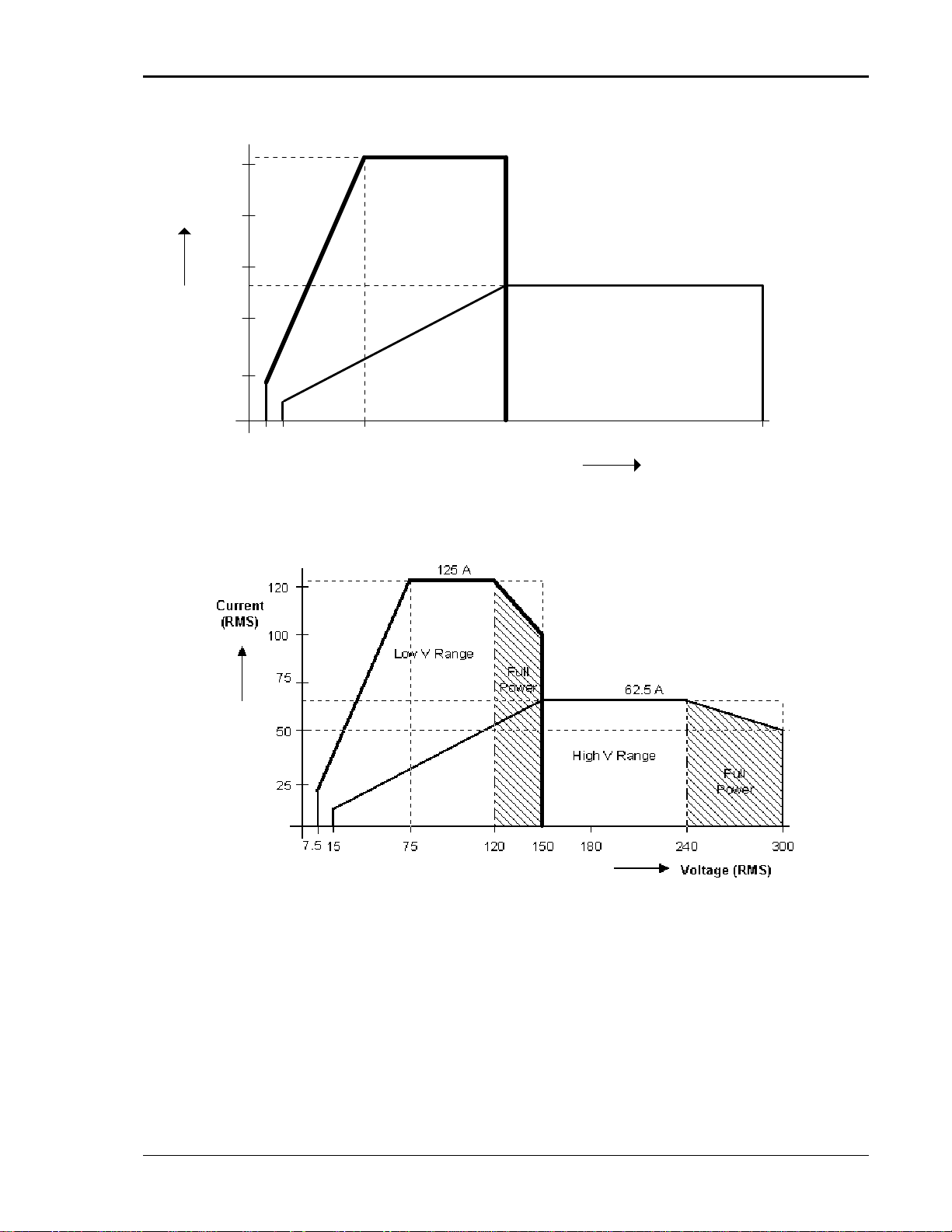
Figure 2-2: MX45-3 Voltage / Current Rating Chart for 150/300 V AC Ranges – Max Rating.
75 300
150
Voltage (RMS)
Figure 2-3: Voltage / Current Rating Chart for 150/300 V AC Ranges – Derated.
MX Series 17
Page 18
User Manual – Rev AJ California Instruments
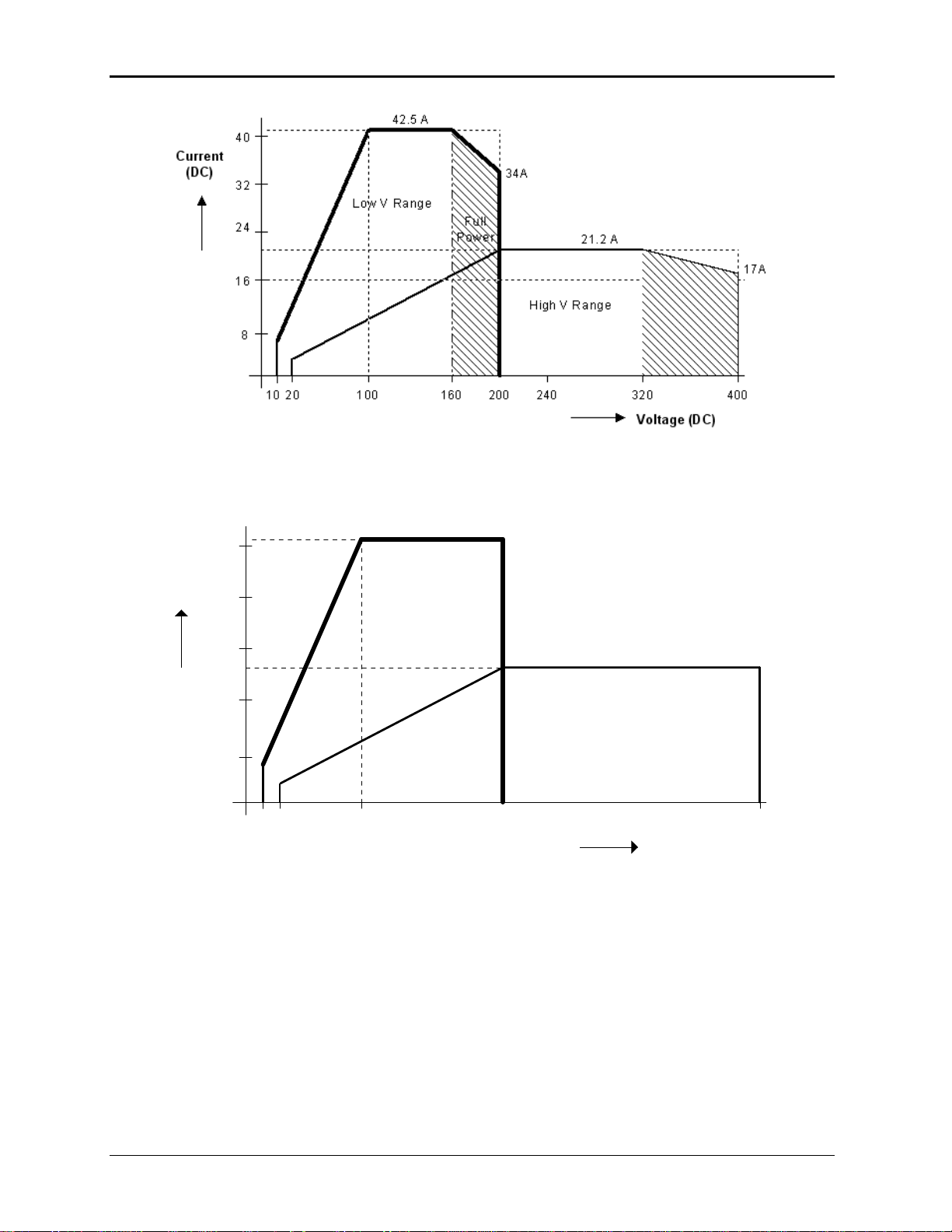
Figure 2-4: MX30-3 Voltage / Current Rating Chart for 200/400 V DC Ranges
50 A
50
Current
(DC)
40
Low V Range
30
25 A
20
High V Range
10
20
40
Figure 2-5: MX45-3 Voltage / Current Rating Chart for 200/400 V DC Ranges – Max. Rating
100 400
200
Voltage (DC)
18 MX Series
Page 19
User Manual – Rev AJ California Instruments
62.5 A
60
50
Current
(DC)
40
30
20
10
0
20 40 100 150 200 300 400
Full
Power
31 A
25 A
Full
Power
Voltage (DC)
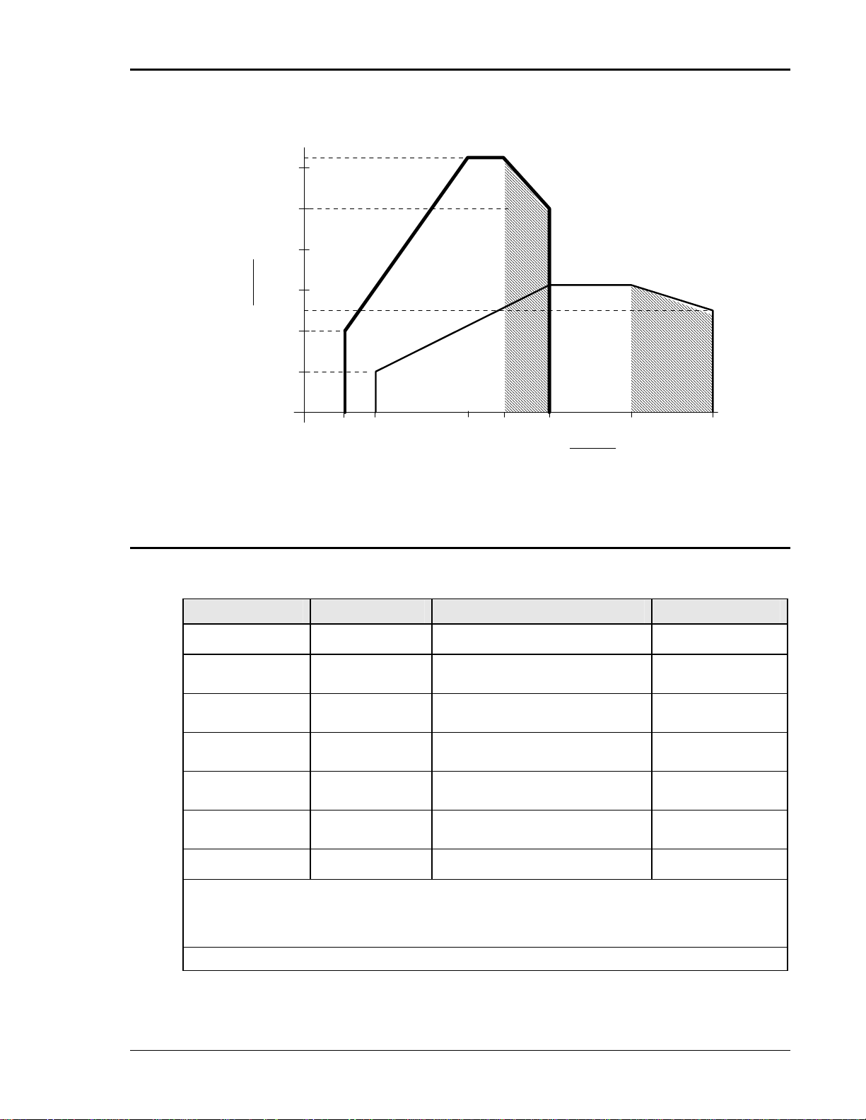
Figure 2-6: Voltage / Current Rating Chart for 200/400 V DC Ranges – Derated
2.1.3 AC Measurements
Measurement specifications apply to MX30-3 / MX30-3Pi / MX45-3 or MX45-3Pi in three-phase
mode. See notes for other models and configurations.
Parameter Range
Frequency 16.00 - 820.0 Hz 0.01% + 0.01 Hz 0.01 to 81.91 Hz
RMS Voltage 0 - 400 Volts 0.05V + 0.02%, <100 Hz
RMS Current 0 - 150 Amps 0.15A + 0.02%, <100 Hz
Peak Current 0 - 400 Amps 0.15A + 0.02%, <100 Hz
VA Power 0 - 15 KVA 30 VA + 0.1%, <100 Hz
Real Power 0 - 15 KW 30 W + 0.1%, <100 Hz
Power Factor
(>0.2kVA)
Note: Accuracy specifications are valid above 100 counts. For current and power measurements,
specifications apply from 2% to 100% of measurement range. Current and Power range and accuracy
specifications are times three for MX45-1, MX60, MX90 and MX135 or MX30-3Pi / MX45-3Pi in singlephase mode.
Note: Power factor accuracy applies for PF > 0.5 and VA > 50 % of max.
Accuracy ()
0.1V + 0.02%, 100-820 Hz
0.3A + 0.02%, 100-820 Hz
0.3A + 0.02%, 100-820 Hz
60 VA + 0.1%, 100-820 Hz
60 W + 0.1%, 100-820 Hz
0.00 - 1.00 0.01, <100 Hz
0.02, 100-820 Hz
Resolution
0.1 to 500 Hz
0.01 Volt
0.01 Amp
0.01 Amp
10 VA
10 W
0.01
MX Series 19
Page 20
User Manual – Rev AJ California Instruments
p
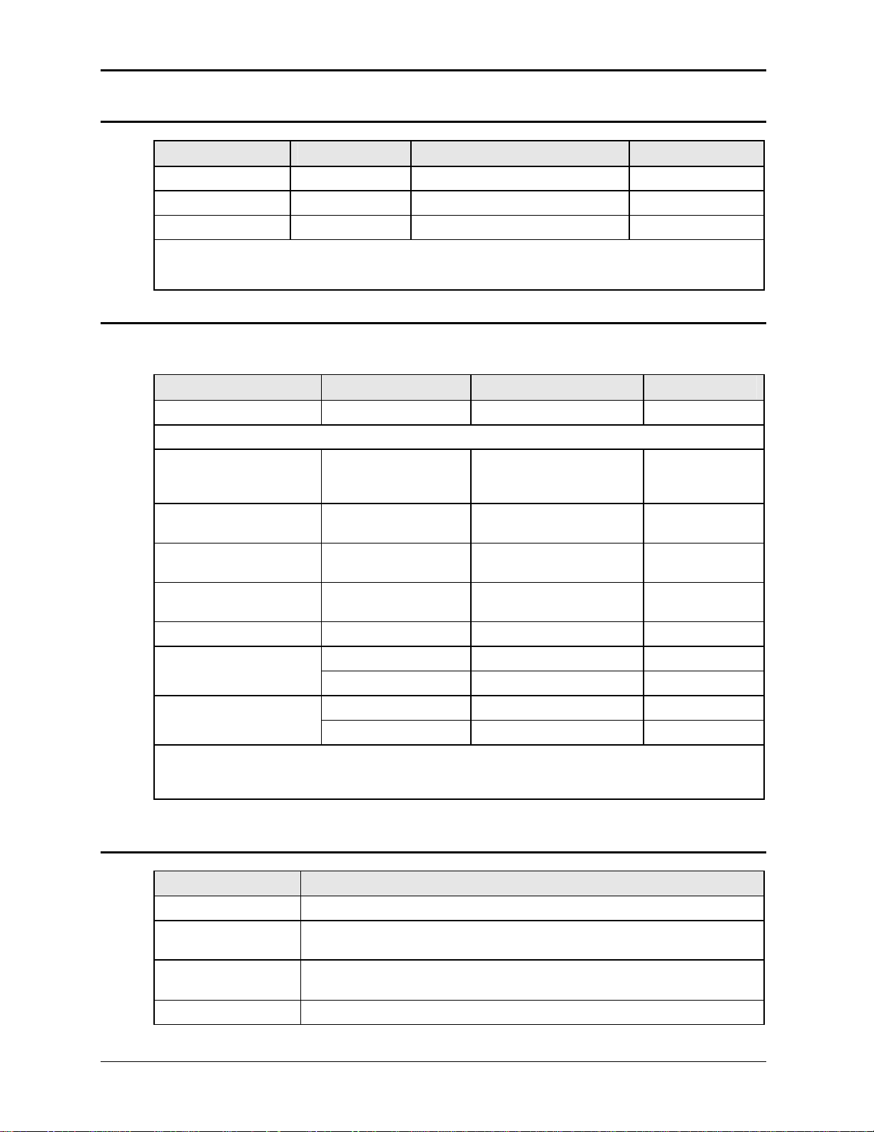
2.1.4 DC Measurements
Parameter Range
Voltage 0 - 400 Volts 0.5 Volts 0.1 Volt
Current 0 - 400 Amps 0.5 Amps 0.01 Amp
Power 0 - 10 kW 30 W 10 W
Note: Accuracy specifications are valid above 100 counts. For current and power measurements,
specifications apply from 2% to 100% of measurement range. Current and Power accuracy and
resolution s
ecifications are times three for MX30-1, MX45-1, MX60, MX90 and MX135 or MX30-3Pi /
2.1.5 Harmonic Measurements (Pi controller)
Harmonic measurement specifications apply to MX30-3, MX45-3, MX30-3Pi and MX45-3Pi in
three-phase mode. See notes for other models and configurations.
Parameter Range
Frequency fundamental 16.00 - 820 Hz 0.03% + 0.03 Hz 0.01 Hz
Frequency harmonics
MX45-3, MX45-3Pi in 3
phase mode, MX60,
MX90, MX135:
Series I
Series II
MX45-1, MX45-3Pi in 1
phase mode:
32.00 Hz – 6.67 KHz
32.00 Hz – 16 KHz
Accuracy ()
Accuracy ()
0.03% + 0.03 Hz 0.01 Hz
Resolution
Resolution
Series I
Series II
Phase 0.0 - 360.0° 2° typ. 0.5°
Voltage Fundamental 0.75V 0.01V
Harmonic 2 - 50 0.75V + 0.3% + 0.3%/kHz 0.01V
Current Fundamental 0.5A 0.1A
Harmonic 2 - 50 0.15A + 0.3% + 0.3%/kHz 0.1A
Note: For current measurements, specifications apply from 2% to 100% of measurement range.
Current range and accuracy specifications are times three for MX30-1, MX45-1, MX60, MX90 and
MX135 or MX30-3Pi / MX45-3Pi in single-phase mode.
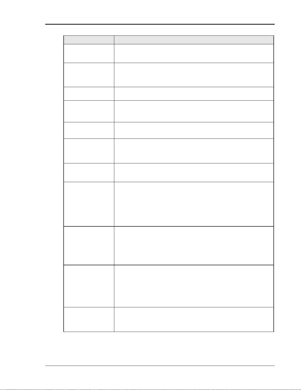
2.1.6 System Specification
Parameter Specification
External Modulation: 0 to 10%
Synchronization
Input:
Trigger Input: External trigger source input. Requires TTL level input signal. Triggers on
Trigger Output:
32.00 Hz - 19.2 KHz
32.00 Hz – 48 KHz
Isolated TTL input for external frequency control. Requires 5V at 5 mA for
logic high.
negative edge. Response time 80 - 100 s.
Programmable through transient list system. 400 s pulse for voltage or
0.03% + 0.03 Hz 0.01 Hz
20 MX Series
Page 21
User Manual – Rev AJ California Instruments
Parameter Specification
frequency change. Isolated TTL output. Output reverts to Function strobe
when not uses as Trig Out. This function is mutually exclusive with the
Function Strobe output.
Function Strobe:
Output Status: Monitors status of output relay. Isolated TTL output. High if output relay is
Non volatile memory
storage:
Waveforms Sine (Models with Standard controller)
Transients Voltage: drop, step, sag, surge, sweep
IEEE-488 Interface: SH1, AH1, T6, L3, SR1, RL2, DC1, DT1
RS232C Interface: Bi-directional serial interface
Active for any voltage or frequency program change. 400 s pulse for voltage
or frequency change. Isolated TTL output. This function is mutually exclusive
with the Trigger Output. Same output is used for Trigger Output if Trigger
Output is programmed as part of list system.
closed, low if output relay is open.
Series I: 8 complete instrument setups and transient lists, 32 events per list.
Series II: 16 complete instrument setups and transient lists, 100 events per
list.
Sine, square, clipped, user defined (Models with Pi controller)
Frequency: step, sag, surge, sweep
Voltage and Frequency: step, sweep
Syntax: IEEE 488.2 and SCPI
Response time is 10 ms (typical)
9 pin D-shell connector
Handshake: CTS, RTS
Data bits: 7, 8
Stop bits: 1,2
Baud rate: 9600 to 115,200 bps
Syntax: IEEE 488.2 and SCPI.
Note: Disconnect any USB connection when using the RS232 interface.
USB Interface: Standard USB 1.1 peripheral.
Data transfer rate: 460,800 bps
Syntax: IEEE 488.2 and SCPI.
Note: Use of the USB port to control more than one power source
from a single PC is not recommended, as communication may not be
reliable. Use GPIB interface for multiple power source control.
LAN Interface: Option –LAN. When the LAN interface is installed, the RS232 interface is
disabled.
RJ45 Connector, 10BaseT, 100BaseT or 1000BaseT,
Data transfer rate: 460,800 bps
Protocol: TCP/IP.
Syntax: IEEE 488.2 and SCP
Note: Disconnect any USB connection when using the LAN interface.
Current Limit Modes: Two selectable modes of operation:
1. Constant current mode (voltage folds back with automatic recovery)
2. Constant voltage mode with trip-off (Relays open).
MX Series 21
Page 22
User Manual – Rev AJ California Instruments
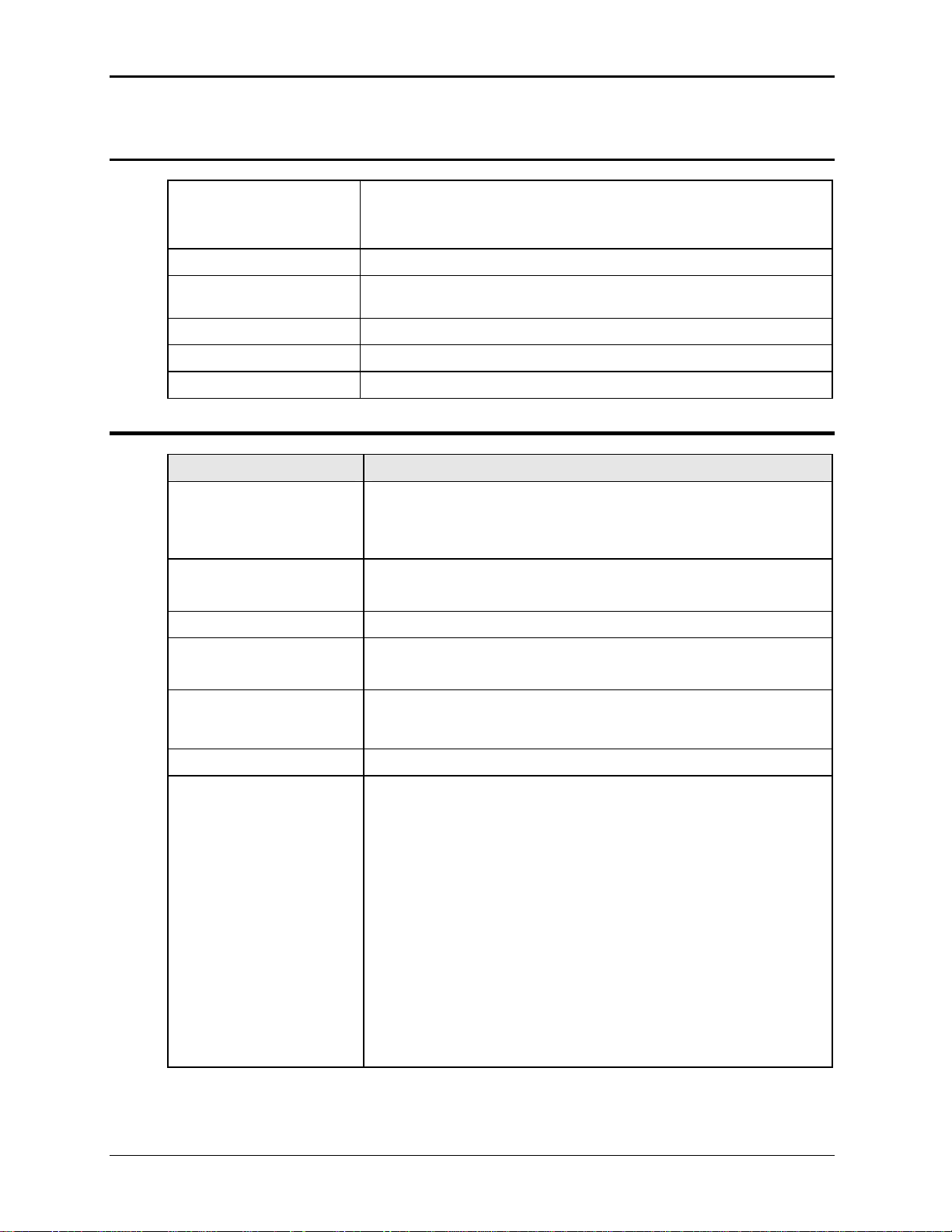
2.1.7 Unit Protection
Input Over current: In-line fast acting fuses. Check fuse rating in Service and Maintenance
section. Ratings will depend on AC input configuration settings.
Circuit breaker for LV supply.
Input Over voltage: Automatic shutdown.
Input Over voltage
Transients:
Output Over current: Adjustable level constant current mode with programmable set point.
Output Short Circuit: Peak and RMS current limit.
Over temperature: Automatic shutdown.
2.2 Mechanical
Parameter Specification
Dimensions:
(for each MX chassis)
Unit Weight:
(for each MX chassis)
Material: Steel chassis with aluminum panels and covers.
Finish: Light textured painted external surfaces.
Cooling: Fan cooled with air intake on the front and exhaust to the rear.
Surge protection to withstand EN50082-1 (IEC 801-4, 5) levels.
Height: 50.0” 1270 mm
Width: 28.75” 731 mm
Depth: 34.5” 876 mm
Net: 1150 lbs / 522 Kg approximately
Shipping: 1231 lbs / 560 Kg
Panels semi-gloss polyurethane color no. 26440 (medium gray)
Fans: 6 x 225CFM.
Air displacement 22 Cu Ft/sec. Max.
approximately
Internal Construction: Modular sub assemblies.
Rear Panel
Connections:
(See section 3 for description of connections)
Cable entry and strain relieve for AC input wiring
Cable entry and strain relieve for output wiring
External sense terminal block (Remote voltage sense)
System interface (2x)
Clock and Lock BNC's (requires -LKM or -LKS options)
RS232, USB, GPIB, LAN (option)
Trigger In BNC
Trigger Out BNC
Function Strobe BNC
Output Status
22 MX Series
Page 23

User Manual – Rev AJ California Instruments
2.3 Environmental
Parameter Specification
Operating Temp:
Storage Temp:
Altitude: < 2000 meters
Relative Humidity:
Installation/Over voltage
Category:
Pollution Degree: 2
Indoor Use Only
Vibration: Designed to meet NSTA 1A transportation levels.
Shock: Designed to meet NSTA 1A transportation levels.
2.4 Regulatory
Electromagnetic
Emissions and Immunity:
Acoustic Noise: 65 dBA maximum at 0% to 50% load, 75 dBA maximum greater than
0° to +35 C. (Except in CP mode).
+32° to +104° F.
-40° to +85 C.
-40° to +185° F.
0-95 % RAH, non-condensing maximum for temperatures up to 31C
decreasing linearly to 50% at 40C.
Designed to meet EN50081-2 and EN50082-2 European Emissions and
Immunity standards as required for the “CE” mark.
50% load to 100% load. Measured at one meter.
Safety: Designed to EN 61010-1 European safety standards as required for the
2.5 Front Panel Controls
Controls:
Shuttle knob: Allows continuous change of all values including output calibration and
Decimal keypad: A conventional decimal keypad facilitates quick entry of numerical values
Up/down arrow keys: A set of up and down arrow keys is used to move the cursor position in all
Function keys: Measure key will display most measurement values. Program key will
“CE” mark.
range change.
such as voltage, current limit, etc. The large blue enter key will make the
value you enter effective. Using the SET key allows the user to preset all
parameter values and update them all at once by pressing the Enter key.
menus. This allows quick selection of the desired function or parameter.
show all program parameters. Output on/off key for output relay control.
Phase key will switch display to show program and measured values for
each phase.
MX Series 23
Page 24
User Manual – Rev AJ California Instruments
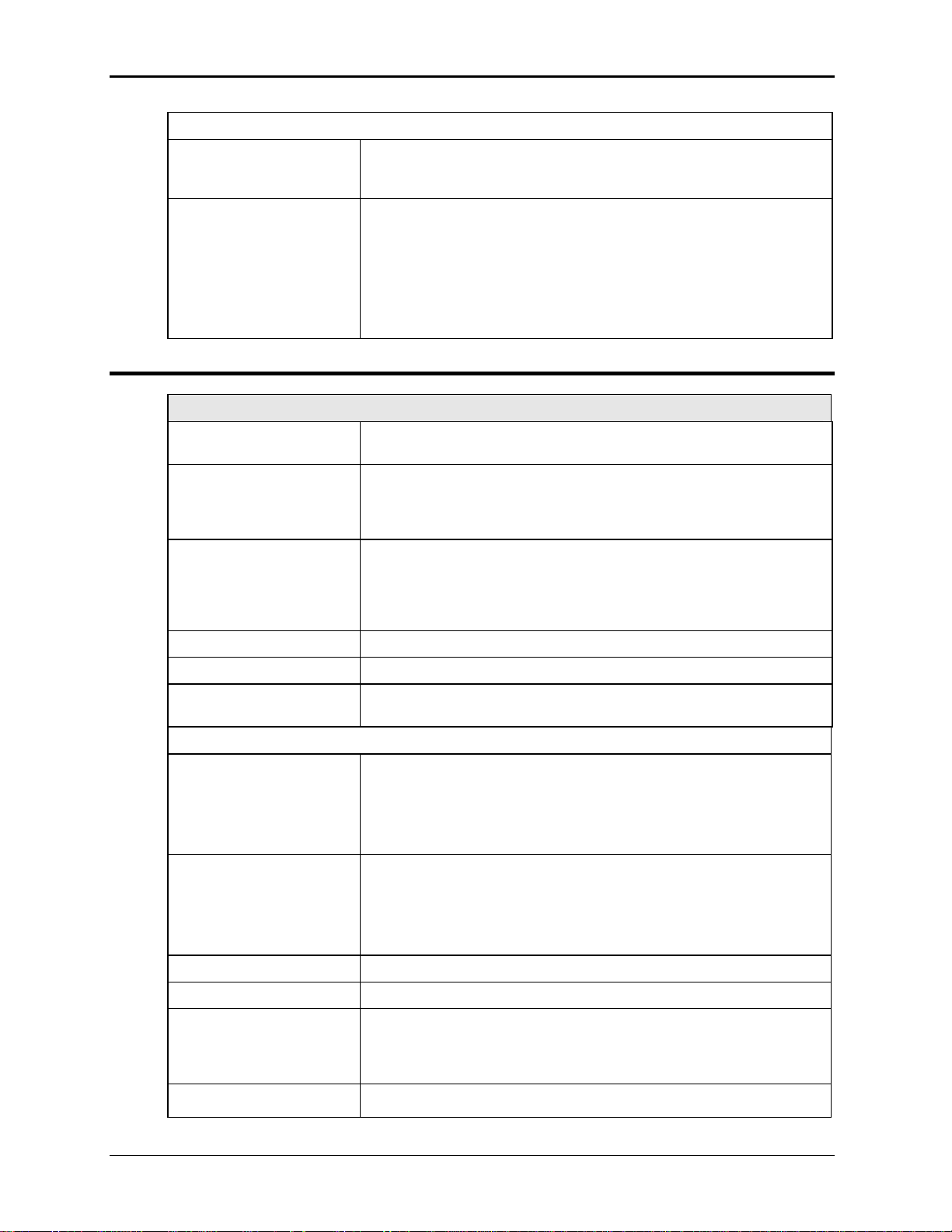
)
Displays:
LCD graphics display: A large high contrast LCD display with backlight provides easy to read
guidance through all setup operations. An adjustable viewing angle
makes it easy to read from all practical locations.
Status indicators: Large and bright status indicators inform the user of important power
source conditions. The Remote lamp informs the user that the unit is
under remote control. The Overload lamp indicates that excessive
current is being drawn at the output. The Over temperature lamp
illuminates when internal heat sink temperatures are too high. The Hi
Range indicator is lit any time the unit is switched to the high voltage
range. The Output On/Off indicator is on when the power source output
relays are closed.
2.6 Special Features and Options
Controller Features
Mode: Switches between 1 and 3 phase outputs. This mode is available on
models MX30-3Pi and MX45-3Pi only.
Parallel Operation: Up to three units can be paralleled in a three-phase configuration (with
one master controller and one or two auxiliary units). (MX60, MX90 and
MX135). Only the master unit requires a controller in this setup. The
auxiliary units are controlled through the system interface.
Clock and Lock Mode:
(Option -LKM and -LKS
required).
Controller: Programmable controller front panel assembly.
Output Relay: Standard output relay feature to isolate power source from the load.
Output On/Off: The output relay can be used to quickly disconnect the load. A green
Firmware / Software Optio ns
- 704 Mil Std 704D & E test firmware.
- 160 RTCA/DO-160D test firmware
- 411 IEC 61000-4-11 test firmware (Pre-compliance)
- 413 IEC 61000-4-13 test firmware
Three units (all with controllers) can be connected in a three-phase
configuration using CLOCK and LOCK connections. Each unit requires
its own controller in this configuration. One unit acts as the master and
provides the reference clock to the auxiliary units.
Note: This option cannot be combined with –HF option.
status indicator displays the status of the output relay.
Mil Std 704A, B, C, & F test software (refer to Avionics Software Manual
P/N 4994-971 for details).
Note: Requires use of MXGui Windows application software provided on
CD ROM CIC496.
RTCA/DO-160E test software (refer to Avionics Software Manual P/N
4994-971 for details)..
Note: Requires use of MXGui Windows application software provided on
CD ROM CIC496.
-A350 Airbus A350 ABD0100.1.8.1 Test software (refer to Avionics Software
Manual P/N 4994-971 for details)..
Note: Requires use of MXGui Windows application software provided on
CD ROM CIC496.
-ABD Airbus A380 ABD0100.1.8 Test software (refer to Avionics Software
Manual P/N 4994-971 for details
..
24 MX Series
Page 25
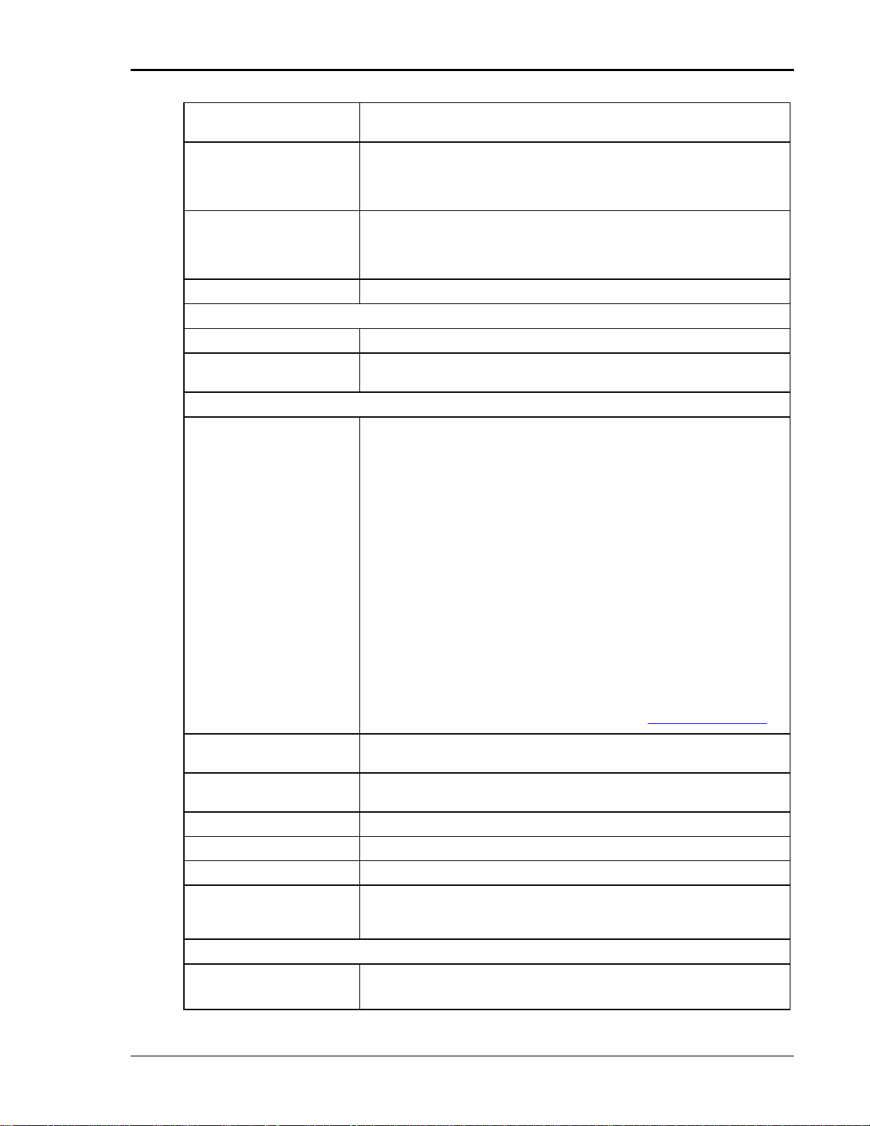
User Manual – Rev AJ California Instruments
j
Note: Requires use of MXGui Windows application software provided on
CD ROM CIC496.
-AMD Airbus AMD24C Test software (refer to Avionics Software Manual P/N
4994-971 for details)..
Note: Requires use of MXGui Windows application software provided on
CD ROM CIC496.
-B787 Boeing 787 Test software (refer to Avionics Software Manual P/N 4994971 for details)..
Note: Requires use of MXGui Windows application software provided on
CD ROM CIC496.
-WHM Watt Hour Measurements (Accuracy and Resolution. See Sec. 2.6.3.)
Output Voltage Range Options
- HV Adds 400 V AC only output range.
- XV Adds customer specified AC only output range. Contact factory for
details.
Misc. Options
-ES Emergency Shut off switch. This option key lock push button is installed
on the front panel of the master MX if ordered with the MX system. When
pushed in, the main AC contactor is opened disconnecting the AC input
power to the MX input transformer. Note that the controller (and LCD
display) will still be powered up but no power is available to the amplifiers
and there will be no output power either. The controller runs off the LV
supply, which must be turned off with the front panel breaker.
After the ES has been pushed, the provided key will be required to
release it. Once the ES button has been released, the MX must be
powered down using the front panel circuit breaker and turned back on to
start up again.
Note: For multibox MX Systems (MX90 and up with more than one
controller and front panel controls, each of which having an ES
emergency switch, to connect a BNC cable between the cabinets for the
ES connection. For 3 or more cabinets with controller, this BNC can be
daisy chained using BNC T connectors.
Note: Do not misplace the 2 keys provided, as no duplicates are
available from CI. If lost, the ES switch must be replaced. In that case,
contact California Instruments customer service. (
-HF Increases maximum output frequency to 905 Hz.
Note: This option cannot be combined with –LKM or -LKS option.
-LAN Adds Ethernet interface (RJ45 connector) for local area network
connection..
-LF Limits maximum output frequency to 500 Hz.
-LKM Clock and Lock system, Master. (Not available with –HF option)
-LKS Clock and Lock system, Auxiliary. (Not available with –HF option)
-MB Multi-box Option. Provides additional controllers in Auxiliary units of
multi-cabinet configurations (MX60, MX90, MX135) to allow individual
MX45 units to be used stand-alone.
External Accessories (External to MX chassis)
7003-416-1
Input / Output wiring junction box. Connects two to six three-phase MX45
cabinet outputs, neutral and ground to a common output terminal block
housed in a metal enclosure
unction box. Can also be used to connect
MX Series 25
Page 26
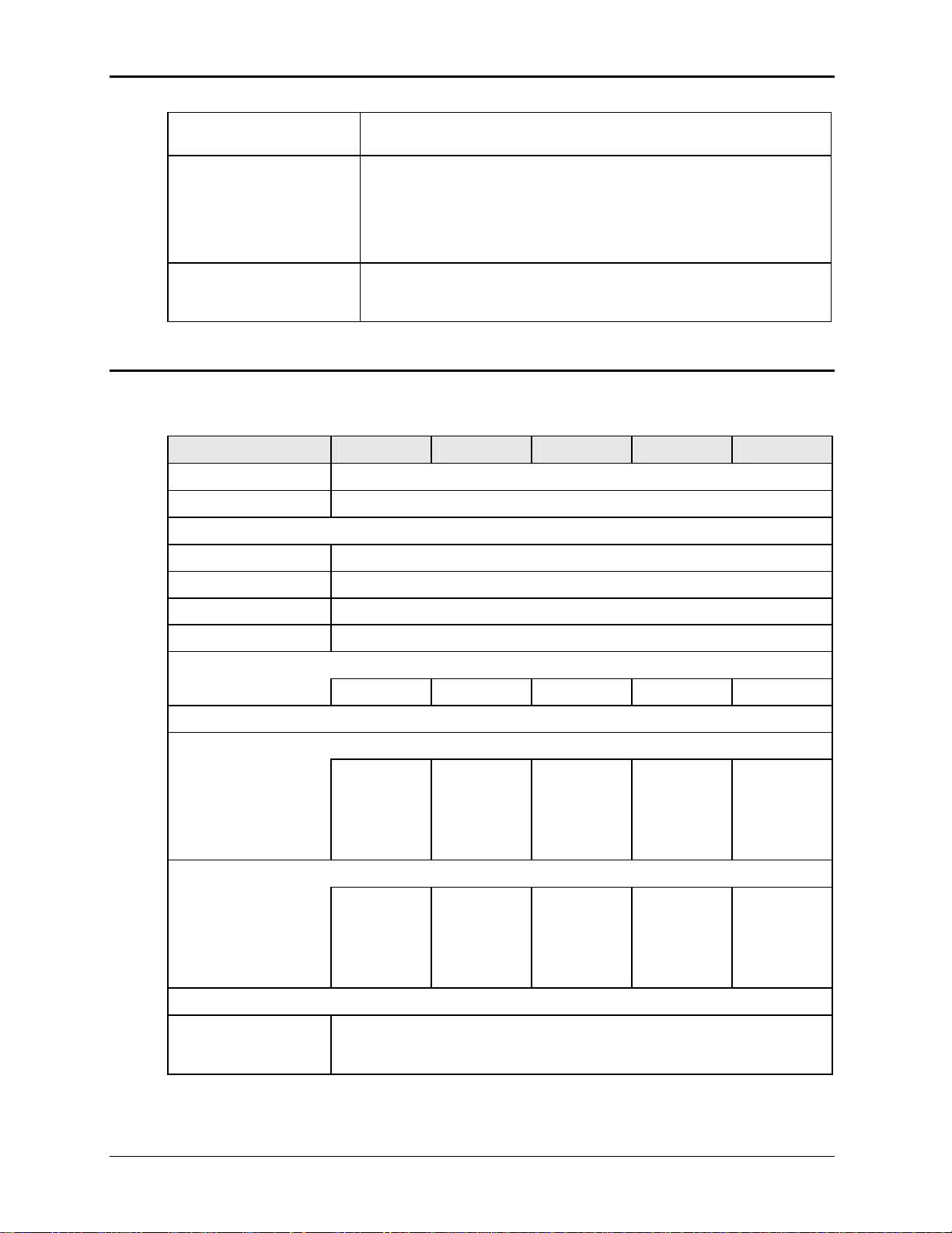
User Manual – Rev AJ California Instruments
multiple MX chassis to common AC input service. See section 3.13 for
details.
7003-424-1
7003-426-1
2.6.1 -HV Option Specifications
The -HV option provides an AC only output range of 0 to 400 Vac L-N. Specifications unique to
the -HV option are shown in the table below.
Output Parameter MX30 MX45 MX60 MX90 MX135
Modes
Pi Controller AC
Voltage:
Ranges (L-N): 0 -400 V
Resolution: 0.1 V
Accuracy: ± 0.25% of Full Scale / ± 1.0 Vac rms
Output noise filter, 3 phase + neutral. May be used to reduce output
noise of MX30 or MX45 when testing EUT’s for conducted emissions.
This is an external filter that attenuates the 250 KHz ripple frequency on
the MX output by > 20 dB. The filter is rated for 125A per phase and 800
Hz. For multi-box configurations, one filter is required per chassis.
Connects to MX30 or MX45 three-phase output terminal only.
Output fuse box. Provides added protection for MX system configurations
consisting of more than 2 MX cabinets. (MX135, MX180, MX225 and
MX270).
Output Coupling AC coupled
Power (total power for all phases, either range, at full scale voltage)
AC Mode 30 KVA 45 KVA 60 KVA 90 KVA 135 KVA
Current
Note: Current, maximum amps per phase available between 50 and 100 % of voltage range.
MX30-1
76.5 A
MX30-3, per
phase
25.5 A
Peak Current
AC Mode MX30-1
337.5 A
MX30-3, per
phase
112.5 A
Frequency:
Range: 45 Hz – 819 Hz
with –LF option: 45 Hz – 500 Hz
with –HF option: 45 Hz – 905 Hz (see also –HF option specification.)
MX45-1
112.5 A
MX45-3, per
phase
37.5 A
MX45-1
337.5 A
MX45-3, per
phase
112.5 A
MX60-3, per
phase
50 A
MX60-3, per
phase
225 A
MX90-3, per
phase
75 A
MX90-3, per
phase
225 A
MX135-3,
per phase
112.5 A
MX135-3,
per phase
337.5 A
26 MX Series
Page 27
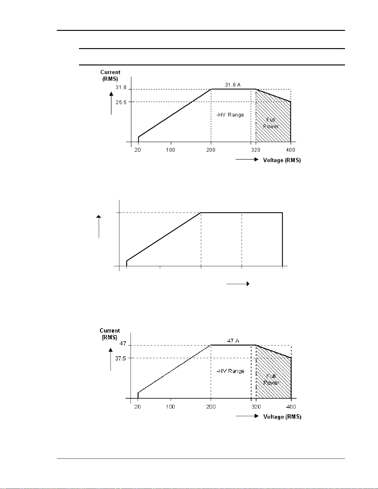
User Manual – Rev AJ California Instruments
Note: Output specifications apply below the Current / Voltage rating lines shown in the
V/I rating chart below.
Figure 2-7: MX30-3 Voltage / Current Rating Chart, -HV Option
Current
(RMS)
37.5 A
37.5
-HV Range
20
100 200 300 400
Voltage (RMS)
Figure ting.
2-8: MX45-3 Voltage / Current Rating Chart, -HV Option – Max. Ra
Figure 2-9: Voltage / Current Rating Chart, -HV Option – Derated.
MX Series 27
Page 28
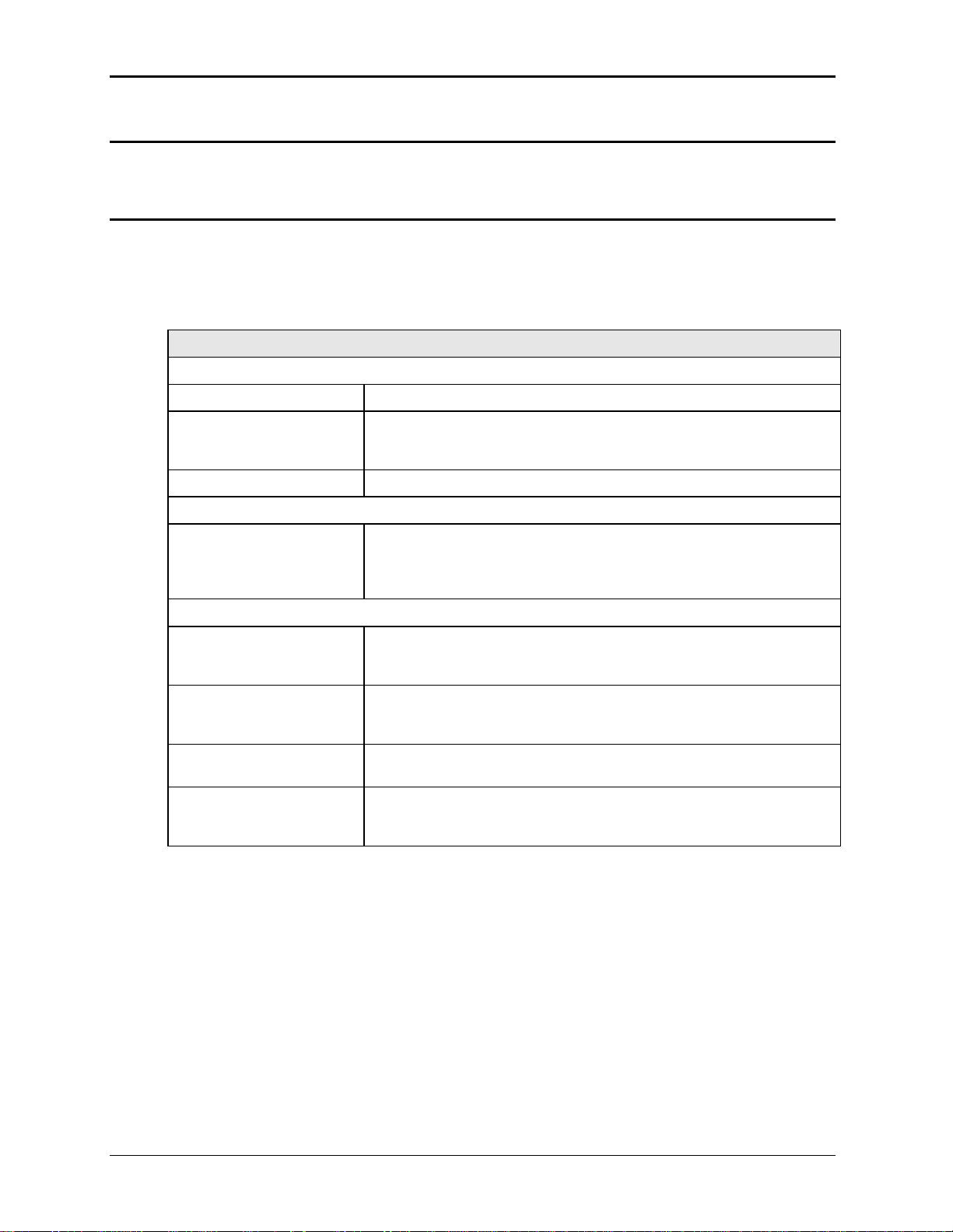
User Manual – Rev AJ California Instruments
2.6.2 -XV Option Specifications
Consult factory for -XV option specifications.
2.6.3 -HF Option Specifications
The -HF option extends the maximum available output frequency from 819 Hz to 905 Hz. Some
restrictions are in effect at this increased output frequency level.
All other specifications of the MX45 system remain unchanged if this option is installed except
as noted in the table below.
-HF Option:
Frequency
Range: -HF option: 16 Hz - 905 Hz
Resolution: 0.01 Hz < from 16.00 to 81.92 Hz
0.1 Hz > from 82.0 to 819.2 Hz
1 Hz > from 820 to 905 Hz
Accuracy: ± 0.01 %
Phase
Accuracy: 16 - 100 Hz: < 1.5°
100 - 500 Hz: < 2°
500 – 819 Hz: < 4°
819 – 905 Hz: < 5°
Voltage
High Voltage Range Maximum voltage at 905 Hz is 290 Vrms
Maximum frequency at 300 Vrms is 875 Hz
See Figure 2-10
Low Voltage Range Maximum voltage at 905 Hz is 145 Vrms
Maximum frequency at 150 Vrms is 875 Hz
See Figure 2-11.
-HV Voltage Range Maximum voltage at 905 Hz is 386 Vrms
Maximum frequency at 400 Vrms is 875 Hz .
Note: If the voltage or frequency settings shown here are exceeded for
any length of time (> 1 sec), the MX may shut down generating an over
temperature fault to protect itself.
28 MX Series
Page 29
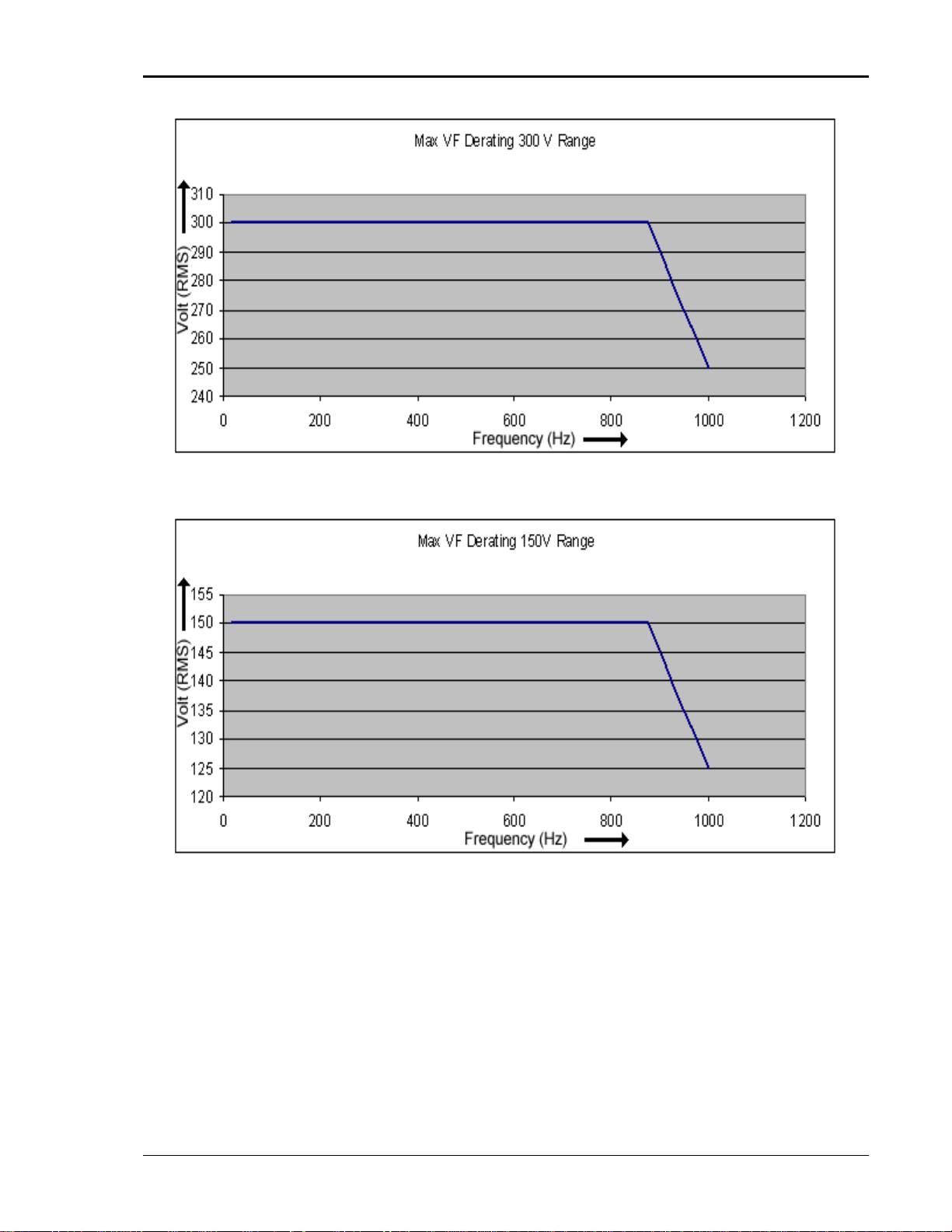
User Manual – Rev AJ California Instruments
Figure 2-10: -HF Option Voltage Frequency Rating 300V range
Figure 2-11: -HF Option Voltage Frequency Rating 150V range
MX Series 29
Page 30

User Manual – Rev AJ California Instruments
2.6.4 -LF Option Specifications
The -LF option limits the maximum available output frequency to 500 Hz. All other specifications
of the MX45 system remain unchanged if this option is installed.
2.6.5 WHM Option Specifications
Watt-hour measurement mode:
Accuracy:
0-6.000KW 0.01KWH + 0.1% <100 Hz
0.02KWH +0.1% 100-819 Hz
>6.000KW Times three of the above specification
Resolution:
0.001 KWH
30 MX Series
Page 31

User Manual – Rev AJ California Instruments
2.7 Supplemental Specifications
Supplemental specifications are not warranted and generally reflect typical performance
characteristics. These characteristics are have been checked on a type test basis only and are
not verified on each unit shipped. They are provided for reference only.
2.7.1 Output
Output Parameter MX30 MX45 MX60 MX90 MX135
Voltage:
Slew rate: > 0.5 V/micro sec
Stability: 0.25 % over 24 hour period at constant line, load and temperature.
Settling time: < 0.5 msec
Frequency:
Temperature
coefficient:
Stability:
Current:
Constant Power
Mode:
2.7.2 Acoustic Noise Levels
Acoustic Noise: Measured at a distance of one meter. (3 ft.)
Front 63 dBA at no load to 68 dBA at full load.
Back 65 dBA at no load to 72 dBA at full load
5ppm per degree C
15 ppm per year
Operation at higher currents but constant power is possible from 80% of
Voltage range (125% of max. current) declining to 100% of maximum current
at 100 % of voltage range for short periods of time or at reduced ambient
temperatures. (< 15 mins @ 30° C). See Figure 2-3 and Figure 2-4.
Note: This mode requires firmware revision 0.27 or higher.
MX Series 31
Page 32

User Manual – Rev AJ California Instruments
2.7.3 Output Noise Spectrum
The MX series is a switching power supply and as such will have a certain amount of switching
noise at its output. While the overall RMS noise is specified, the specific noise spectrum will
differ slightly from unit to unit. The information provided in this section is for reference only.
The output noise can be reduced by using one or more external filters. A suitable filter is the P/N
7003-424-1 (Figure 2-12) available from California Instruments as an option. Attenuation at the
250 kHz ripple frequency is 20 dBuV. The output voltage drop at 800 Hz full load is less than
1Vrms.
Typical output noise spectrum for a standard MX45-3Pi in three phase mode operating at 400
Hz is shown in Figure 2-13 for phase A and Neutral. The same output with the use of the
optional filter is shown in Figure 2-14. For connection information, refer to section 3.14.
MX Filter Specifications
(Model 7003-424-1)
Type
Low Pass Filter Three phase WYE, four wire. (A, B, C and Neutral)
Capability
Frequency range DC, 16 Hz - 800 Hz
Max Voltage 250 Vrms Line to Neutral / 440 Vrms L-L
Phase Current 125 Arms per phase maximum.
Impedance Voltage drop at 800 Hz, 125 A is less than 1 Vrms.
Performance
Attenuation 20 dBuV at 250 KHz.
Physical
Enclosures type Cooper B-Line P/N 16126 SC NK
Dimensions (W x D x H)
Unit: 16” x 12” x 6” / 406 mm x 305 mm x 152 mm
Shipping: 30” x 25” x 11” / 760 mm x 635 mm x 280 mm
Weight Net: 28 lbs / 12.7 Kg
Shipping: 40 lbs / 18.2 Kg
Operating Temp:
0° to +40 C. / +32° to +104° F.
32 MX Series
Page 33

User Manual – Rev AJ California Instruments
ilter option schematic Figure 2-12: MX output f
MX Series 33
Page 34

User Manual – Rev AJ California Instruments
Figure 2-13: MX45 Output Noise 10 KHz – 1 MHz
34 MX Series
Page 35

User Manual – Rev AJ
California Instruments
MX Series
Figure 2-14: MX4 oise 10 KHz - 1 M with optional Filter
Hz 5 Output N
35
Page 36
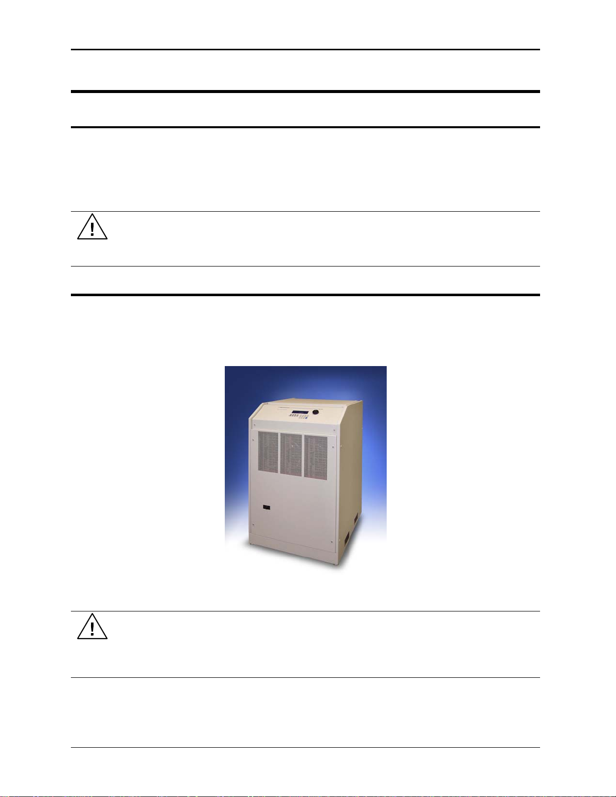
User Manual – Rev AJ California Instruments
3. Unpacking and Installation
3.1 Unpacking
Inspect the unit for any possible shipping damage immediately upon receipt. If damage is
vident, notify the carrier. DO NOT return an instrument to the factory without prior approval.
e
Do not destroy the packing container until the unit has been inspected for damage in shipment.
If possible, retain the container (wooden crate) in the event the system ever has to be return
to the factory for either repair or upgrades
WARNING: This power source weighs approximately 1150 lbs / 522 Kg. Obtain
adequate help when moving the unit. Make sure the location (floor) in which the MX
Series unit(s) will be installed can support the weight of the unit(s).
3.2 Power Requirements
The MX Series power Source has been designed to operate from a three-phase, three wire
(Wye or Delta) AC input line. A protective earth connection is required as well. (PE).
ed
Available three-phase input settings are 208 V
(option -400), or 480 V
(option -480).
LL
Figure 3-1: The MX45 Power Source
(option -208), 230 V
LL
(option -230), 400 V
LL
LL
CAU 30V unit, the result TION: Do not connect 400 or 480V into a unit set for 208 or 2
could be a severely damaged unit. Always check the input rating on the model
number tag before connecting AC input power. Consult factory if input settings have
to be changed.
36 MX Series
Page 37
User Manual – Rev AJ California Instruments
3.3 Mechanical Installation
The MX's are completely self-contained power sources. They are to be used free standing on a
solid surface. The units are fan cooled, drawing air in from the front and exhausting at the rear.
The front and back of each unit must be kept clear of obstruction and a 6” clearance must be
maintained to the rear. Special consideration of overall airflow characteristics and the resultant
internal heat rise must be considered at all times to avoid self heating and over temperature
problems.
3.4 AC Input Connections and Wiring
Three-phase Delta or Y AC input voltage of sufficient amperage (consult AC input specifications
for maximum AC current per phase) is required to power the MX Series.
Note: AC power should be routed through a properly sized and rated three-phase
PROTECTIVE CIRCUIT BREAKER or similar branch circuit protection device with
disconnect capability. This will protect building wiring and other circuits from
possible damage or shutdown in case of a system problem. It will also facilitate
removing AC input power to the MX system in case of service or reconfiguration
requirements.
Note: AC input wiring and connections must conform to local electrical safety codes
that apply. Always consult a qualified electrician prior to installation of any MX
System.
AC input connections are to be made directly to the input fuse block. The input fuse block is
located on the lower left hand corner of the front of the MX chassis. To access the input fuse
connection block, the protective front cover needs to be removed first.
CAUTION: Always disconnect any input power completely when removing
any protective cover and allow the internal capacitors to fully discharge
(minimum of 15 mins) before removing any cover.) See Figure 3-2 for details.
No wiring for AC input connections is provided with the MX Series and must be provided by the
end user or installer. Input wiring should be entered through the right hand side (when facing the
back of the MX cabinet, see Figure 3-4) wire access opening located at the rear bottom of the
MX chassis. A wire channel (marked as [2] in figure below) is provided below the input
transformer to allow the input wiring to be routed to the front of the unit where the connections
are to be made.
WARNING: The power source's input connection wiring gage (size)
must be sized for the maximum input current rating to ensure user safety and
avoid possible power source damage, regardless of the actual output load.
MX Series 37
Page 38

User Manual – Rev AJ California Instruments
Figure 3-2: Location of AC Input Fuse Block and Chassis Ground Connection -
Front View, Access Panel Removed
Note: To comply with product safety requirements, EARTH GROUND must be
connected to the chassis of the AC power system using the ground stud located
directly below the AC input fuse block. Use a Green/Yellow ground wire.
Note: DO NOT USE THE NEUTRAL CONNECTION OF A 3 PHASE Y AC POWER
CONNECTION IN PLACE OF A TRUE EARTH GROUND CONNECTION. AC power
system neutrals cannot be used for protective earth ground.
The mains source must have a current rating equal to or greater than the input fuses and the
input wiring must be sized to satisfy the applicable electrical codes. The front cover must be reinstalled prior to use and the strain relief provisions located at the rear bottom of the unit must be
used to maintain protection against hazardous conditions.
38 MX Series
Page 39

User Manual – Rev AJ California Instruments
3ø
AC Line
Input
PROTECTIVE
GROUND
Figure 3-3: MX Series AC Input Connection Diagram (Rear view)
EXTERNAL
CIRCUIT
BREAKER
AC MAINS
3 PHASE
MX Series 39
Page 40

User Manual – Rev AJ California Instruments
The input power cables and protective circuit breaker used must be large enough to handle the
input current and input voltage of the power source and must conform to local electrical codes.
C nsult a q
o ualified electrician prior to installation. Table 3-1 shows the size of the cables that
may be used per MX cabinet. Note that wires must be sized to accommodate the worst-case
maximum current that may occur under low line c
onditions. Local electrical codes may also
require different wire types and sizes. These ratings should also be used when selecting a
circuit breaker or equivalent disconnect device.
le
Cable ngths must not exceed twenty-five (25) feet. For lengths greater than 25 feet, calculate
the voltage drop from the following formula:
2 X DISTANCE X CABLE RESISTANCE PER FT. X CURRENT = VOLT DROP
Table 3-1: Suggested Input Wiring Sizes for each MX Cabinet *
Nominal Line
Voltage
480 V 75 A
400 V 90 A
230 V 157 A
208 V 175 A
Load Current
@ low line
6 AWG 26.24 13.3
RMS
4 AWG 41.74 21.1
RMS
2 AWG 66.36 33.6
RMS
1 AWG 83.69 42.4
RMS
Wire Gauge (US) Circular Mils
(Kcmils)
Metric (mm2)
* Using high temperature rated wire. Always consult the National Electrical Code and/or local code
regulations for proper rating and size of wire cabling prior to installation.
CAUTION: Capacitors in the power source may hold a hazardous electrical charge
even if the power source has been disconnected from the mains supply. Allow
capacitors to discharge to a safe voltage before touching exposed pins of mains
supply connectors.
Power modules need at least 15 Minutes to discharge to safe levels before they can
be removed.
3.5 AC On/Off Circuit Breaker on MX Series front panel.
It is important to understand the purpose and operation of the On/Off circuit breaker of the MX
Series located on the lower left side of the front panel. This is a 2A rated breaker that is used to
engage and protect the LV Power supply of the MX chassis only. The LV Power supply
provides DC bias power to the entire MX system. The AC input power is routed through a set of
three AC line fuses (F1, F2 and F3) located in the lower left bottom corner of the MX. (See
Figure 3-2 for fuse locations). These fuses protect the three MX amplifiers and the AC input
transformer from excessive input currents. The AC input power is connected to the input
transformer through a large three-pole contactor. Removing AC power to the LV Power Supply
by opening the front panel circuit breaker (moving the lever to the down (OFF) position) will
cause this contactor to loose its coil voltage and will result in it opening and disconnecting the
input transformer and amplifier from AC mains input.
Note: If any MX system failure has occurred on any part of the MX system, AC input
power must be removed immediately and
not restored until the system has been
inspected by a qualifier service technician.
Always turn off the On/Off Circuit breaker before re-applying AC input power.
40 MX Series
Page 41

User Manual – Rev AJ California Instruments
CAUTION: The AC input fuses can only be checked is the MX unit is completely
de-energized and disconnected from any AC power input.
Note: Under no circumstances should AC input power be applied if one or more of the
AC input line fuses have failed and opened up.
Figure 3-4: Rear Panel
MX Series 41
Page 42

User Manual – Rev AJ California Instruments
3.6 Outpu ions t Connect
3.6.1 O tpuu t Wiring
The output terminal blocks, TB1A and TB1B are located at the front of the unit behind the
bottom access panel. See Figure 3-2 for details.
terminal block TB1A. The phase outputs are Three phase output line connections are made to
labeled A, B and C. The neutral connection (if needed) can be made on terminal block TB1B. If
the model used is an MX30-1, MX30-3Pi, MX45-1 or MX45-3Pi with single-phase capability, the
single phase A output connection is available on TB1B as well. Note that the neutral for either
single or three-phase mode is always located on TB1B. The neutral connection is always
required for single-phase output mode on an MX30-3Pi or MX45-3Pi and may be used if needed
for the EUT for all three-phase output modes.
The external sense inputs allow the power system output voltages to be monitored directly at the
load and must be connected at TB2 when the sense is programmed for external. The external
sense input does not have to be connected when Internal Sense is programmed. The external
sense wires are to be connected to TB2 on the rear panel and should be run using a twisted
shielded cable. See Figure 3-4 for location of TB2 and Figure 3-5 for shield connection detail.
Note: For External Sense connection, a shielded cable MUST be used with the shield
connected to chassis ground at the Ext. Sense connector. (See Figure 3-5).
External sense is recommended for multi-cabinet systems is the output wiring from the cabinets
to the common output terminal block supplied is not of equal length.
Figure 3-5: External sense cable shield connection to chassis ground
Note: The output of the power source is isolated from the input line and floating with
respect to chassis ground. If needed, either side (HI or LO) may be grounded.
If the EUT changes frequently, you may want to consider using some quick disconnect scheme
external to the MX so it will not be necessary to power down the MX and remove the front
42 MX Series
Page 43

User Manual – Rev AJ California Instruments
covers. This can tak
and voltage rating. (
The output power cables must be large enough to prevent a total voltage drop exceeding 1%
the rated output voltage between the power source and the load. Table 3-2 shows the size o
e the form of a panel-mounted socket (1 or 3 phase) of sufficient current
Not supplied with MX)
of
f
the cables that may be used. Note that wires must be sized to accommodate the maximum
current that is available. This may be a function of the voltage range and phase mode on some
MX models. If the MX has more than one output voltage range, size the wires for the lowest
available voltage range as the currents will be highest in that range.
Cable lengths must not exceed twenty-five (25) feet. For lengths greater than 25 feet, calculate
the volta e drop
g from the following formula:
2 X DISTANCE X CABLE RESISTANCE PER FT. X CURRENT = VOLT DROP
Table 3-2: Suggested Output Wiring Sizes *
Load Current Wire Gauge (US) Circular Mils
Metric (mm2)
(kcmils)
65 AMPS 6 AWG 26.24 13.3
130 AMPS 4 AWG 41.74 21.1
260 AMPS 1/0 AWG 105.6 53.5
400 AMPS 2/0 AWG 133.1 67.4
Note: high temper re rate ways consult the National Electrical Code Use atu d wire. Al
and/or local code regulations for proper rating and size of wire cabling prior to
installation.
MX Series 43
Page 44

User Manual – Rev AJ California Instruments
Output Terminal Blocks
The MX30-3, MX30-3Pi, MX45-3 and MX45-3Pi have two output terminal blocks, TB1A and
TB1B. The MX45-1 only has one output terminal block, TB1B. The terminal blocks are large
enough to accommodate the recommended wire gauge sizes shown in Table 3-2. The terminal
blocks are located in the lower right corner on the front of the unit. The front panel needs to be
removed to access these terminal blocks.
CAUTION: REMOVE ALL INPUT POWER TO THE MX BEFORE REMOVING
THE FRONT PANEL.
The correct standard size Allen wrenches for connecting output wiring to TB1A and/or TB1B are
supplied with each MX in the ship kit. Look for a brown envelope. If the correct tools cannot be
found, contact California Instruments customer service at
Terminal block TB1B always provides the output neutral connection, regardless of the phase
mode (1 or 3 phase output mode).
In single-phase mode, phase A output is provided through terminal 1 of TB1B.
In three-phase mode, phase A, B and C outputs are provided trough terminals 1, 2 and 3 of
TB1A respectively.
Connector Terminal Mode Output
TB1A 1 3 Phase Phase A
2 3 Phase Phase B
3 3 Phase Phase C
TB1B 1 1 Phase Phase A
2 1 and 3 Phase Neutral
Table 3-3: Output Terminal connections.
Figure 3-6: Location of Output Terminals (Front view)
44 MX Series
Page 45
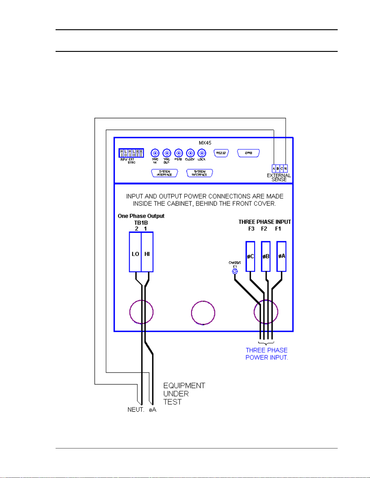
User Manual – Rev AJ California Instruments
3.6.2 MX45-1, MX30-1, MX30-3Pi and MX45-3Pi 1 ø mode Output Wiring Diagram
Figure 3-7 shows the required output connections for a MX30-1, MX45-1, MX30-3Pi or MX45
3Pi in single-phase mode output configuration (rear-view perspective). See section 3.6.3 for the
MX30-3Pi or MX45-3Pi in three-phase mode.
Always disconnect all input power from the MX before removing the front panel cover that
provides access to the input and output terminal connections. Route the wires from the back of
the MX to the front in the provided cable guides.
Figure 3-7: MX30-1 / MX45-1 Output Wiring (Rear view)
MX Series 45
Page 46

User Manual – Rev AJ California Instruments
3.6.3 MX30-3, MX45-3, MX30-3Pi and MX45-3Pi 3ø mode Output Wiring Diagram
Figure 3-8 shows the required output connecti
ons for a MX30-3, MX45-3 three phase or an
MX30-3Pi and MX45-3Pi in three-phase mode output c
section 3.6.2 for the MX30-3Pi or
Always disconnect all input power from the MX
provides access to the input and output terminal
MX45-3Pi in single-phase mode.
before removing the front panel cover that
connections. Route the wires from the back of
the MX to the front in the provided cable guides.
onfiguration (rear-view perspective). See
Figure 3-8: MX30-3 / MX45-3 Output Wiring (Rear view)
46 MX Series
Page 47
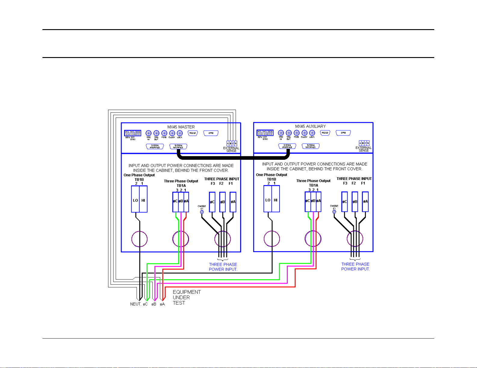
User Manual – Rev AJ California Instruments
3.6.4 MX60 or MX90 Output Wiring Diagram
Figure 3-9 shows the required output connections for a MX60-3 or MX90-3 three phase output configuration (rear-view perspective).
Always disconnect all input power from the MX60 or MX90 before removing the front panel cover that provides access to the input and
output terminal connections. Route the wires from the back of the MX30 or MX45 chassis to the front in the provided cable guides. MX60,
MX90 and MX135 systems are shipped with external output terminal blocks that enable the output wiring from two or three chassis to be
combined, providing a single point of connection to the EUT. These blocks are not enclosed however.
Figure 3-9:MX60, MX60-MB, MX90 or MX90-MB Output Wiring (Rear view)
MX Series 47
Page 48

User Manual – Rev AJ California Instruments
Figure 3-10: Two MX's in Clock and Lock mode Output Wiring (Rear view)
48 MX Series
Page 49

User Manual – Rev AJ California Instruments
3.6.5 MX135 Output Wiring Diagram
Figure 3-11 shows the required output connections for a MX135-3Pi or MX135-3Pi-MB three phase output configuration (rear-view
perspective). Always disconnect all input power from the MX135 before removing the front panel cover that provides access to the input
and output terminal connections. Route the wires from the back of the MX45 chassis to the front in the provided cable guides. Note that
the master is shown in the center in this drawing. MX60, MX90 and MX135 systems are shipped with external output terminal blocks that
enable the output wiring from two or three chassis to be combined, providing a single point of connection to the EUT. These blocks are
not enclosed however.
MX Series 49
Page 50

User Manual – Rev AJ California Instruments
Figure 3-11: MX135 or MX135-MB Output Wiring (Rear view)
50 MX Series
Page 51

User Manual – Rev AJ California Instruments
Figure 3-12: Three MX's in Clock and Lock mode - Output Wiring (Rear view)
MX Series 51
Page 52

User Manual – Rev AJ California Instruments
3.6.6 MX180, MX225, and MX270 Output Wiring Diagram
Figure 3-11 shows the required output connections for a MX180-3Pi through MX270-3Pi three phase output configuration (rear-view
perspective). For MX180, only 4 cabinets are used and for MX225 only 5 but otherwise the wiring diagrams are the same so only the
complete MX270-3Pi configuration is shown.
Always disconnect all input power from the MX180, MX225 or MX270 before removing the front panel cover that provides access to the
input and output terminal connections. Route the wires from the back of the MX45 chassis to the front in the provided cable guides.
For any of these system configurations, it is recommended to use the optional wiring junction box (P/N 7003-416-1). See section 3.13 for
details. All output wires must be of equal length so it is advisable to place the master unit at or near the physical center of the set of units.
52 MX Series
Page 53

User Manual – Rev AJ
California Instruments
MX Series
Figure 3-13: MX18 X225 or MX270 iring (Rear view)
Output W0, M
53
Page 54
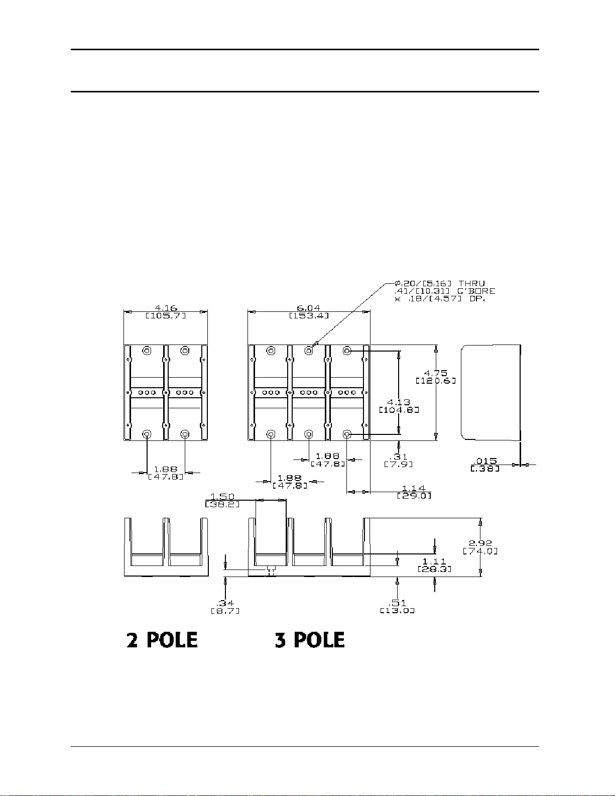
User Manual – Rev AJ California Instruments
3.6.7 Multi-Chassis Output Connections
If two or more MX chassis are used to form a
single power system, the outputs of all chassis
need to be combined (paralleled by phase). This can be done directly at the EUT if convenient
or usin he pro heav lti-chassis
MX systems, one 2-position blo
g t vided y-duty terminal blocks. Two blocks are provided with mu
ck and one 3-position block. These blocks allow up to four wires
to be combined into one larger wire gauge size wire. The outputs of the 2 or 3 MX chassis are
connected on one side of these blocks (Phase A,B and C into the 3 position terminal and the
neutral into the 2 position terminal.). The EUT can be connected to the other side. Note that the
wire size to the EUT should be sized up to accommodate the double or triple currents per
phase
.
The d sions 4.
imen of the supplied terminal blocks are shown in Figure 3-1
Note t even i put, the output neutrals of the MX chassis'
hat f the EUT is a three-phase delta in
must be connected together for t
he system to work correctly.
Figure 3-14: Ship kit Terminal Block dimensions
54 MX Series
Page 55

User Manual – Rev AJ California Instruments
3.7 Connectors - Rear Panel
A number of connectors are located along the top rear covers. These connectors are i
recessed area to protect them from shipment damage.
3.7.1 System rface Inte
WARNING: nte ifornia Instruments The system i rface connectors are for use with Cal
supplied cables, and only between California Instruments equipment.
The Clock and Lock BNC connectors located on the rear panel are used to synchronize and
control the phase shift between the three output
clock a lock s KM (on Master unit) and -LKS (on
ystem. This mode of operation requires the -Lnd
Auxiliary units) options. Se n on this mode of operation.
set of two identical System Interface connectors, P8 and P9 is located on the rear panel of
A
ach MX chassis. The system interface is used to connect the multiple MX30 or MX45 power
e
sources in a Master/Auxiliary configuration to create MX60, MX90 or MX135 models. In these
configurations, only the Master MX30 or MX45 power source has a built-in controller and front
panel.
The same connector is also used to control the optional OMNI-3-75 Reference Impedance.
P8 / P9 Description
1 OUTP: Output ON. Controls state of output relay
n a
s when 3 units are operating as a three-phase
e paragraph 3.10 for more informatio
2 N/C
3 N/C
4 N/C
5 COM: Common. Signal return.
6 OT: Over temperature. Indicates over temperature condition.
7 N/C
8 CLB: Current Limit B. Programmed current limit reference for phase B
9 CSA: Current Sum Phase A
10 CSC: Current Sum Phase C
11 FLT A: Amplifier Fault Phase A
12 FLT C: Amplifier Fault Phase C
13 XFMR: Optional voltage range select. (-HV or -XV option)
14 PARALLEL: Parallel operation control.
15 INPUT ON: Input power status
16 A ERR LO: Error Signal Phase A, low
17 B ERR HI: Error Signal Phase B, high
18 N/C
19 C ERR LO: Error Signal Phase C, Low
MX Series 55
Page 56

User Manual – Rev AJ California Instruments
P8 / P9 Description
20 300 VRNG: 300 V AC Range Select
21 COM: Common. Signal return.
22 /REM OFF: Remote Off Control not
23 COM: Common. Signal return
24 FLK/BYP: Flicker / Bypass OMNI control
25 /OVL: Overload not
26 CLA: Current Limit A. Programmed current limit reference for phase A
27 grammed current limit reference for phase C CLC: Current Limit C. Pro
28 CSB: Current Sum Phase B.
29 N/C
30 FLT B: Amplifier Fault Phase B
31 N/C
32 DC: DC mode control
33 INP OFF: Input power control
34 A ERR HI: Error Signal Phase A, high
35 N/C
36 B ERR LO: Error Signal Phase B, low
37 C ERR HI: Error Signal Phase C, high
3.7.2 Analog Input Connector
Input screw-terminal strip. Functions are called out on rear panel decal. Table shows
connections from left to right when standing at the rear of the MX cabinet.
Pin Description
1 RPV HI. INPUT: Analog input for External Modulation
2 RPV Lo. INPUT: return.
3 EXT SYNC HI INPUT: Analog input for external sync mode.
4 EXT SYNC Lo INPUT: return.
5 RI: INPUT: Remote Inhibit. (See paragraph 3.12.)
6 RI: INPUT: return.
Table 3-4: System Interface Connectors
Table 3-5: Analog Interface Connector
56 MX Series
Page 57

User Manual – Rev AJ California Instruments
3.7.3 BNC Connectors
BNC connectors. Functions are called out on rear panel decal. Table shows connections from
left to right when standing at the rear of the MX cabinet.
BNC Description
1 Trigger Input (TTL input)
2 Trigger Output (T
may n
ot have this output connec ou don’t get an output trigger on this BNC, use the
tion Strobe BNC instead.)
Func
3 Function Strobe (TTL output) (Sa onnection as Trigger Output) me signal c
4 Clock (TTL output on Master / TT input on Auxiliary) L
5 Lock (TTL output on Master / TT on Auxiliary) L input
6 Emergency Shut off inter connec d only on –MB systems with –ES Option. t. Installe
3.7.4 External Sense Connector
Pin Description
1 Phase A sense
Table 3-6: BNC Connectors
TL output) (Same signal connection as Function Strobe. Some units
ted. If y
Table 3-7: BNC Connectors
2 Phase B sense
3 Phase C sense
4 Neutral sense
Table 3-8: External Sense Connector
MX Series 57
Page 58

User Manual – Rev AJ California Instruments
3.7.5 RS232C Serial Interface Connector
An RS232 serial interface connector is located on the rear panel on all models. Note that two
versions of the RS232 exist on the MX model series depending on the age of the unit. Older
models can be identified by the fact that they will not have a USB interface.
Pin Name Direction
1 N/C
2 TxD Output
3 RxD Input
4 N/C
5 Common Common
6 N/C
7 CTS Input
8 RTS Output
9 N/C
Table 3-9: RS232 Connector pin out – MX with RS232 and USB.
Pin Name Direction
1 N/C
2 RxD, Receive data Output
3 TxD. Transmit data Input
4 DTR, Data Terminal Ready DTR, Data Terminal Ready
5 Common Common
6 N/C N/C
7 RTS, Request to Send Output
8 N/C N/C
9 N/C N/C
Table 3-10: RS232C Connector pin out – MX with RS232 but no USB
On MX models without a USB interface, a special RS232 cable is required to connect to a PC.
With these MX models, a special 13 foot / 4 meter long cable is supplied in the MX Series shipkit. The wiring diagram for this cable is shown below in case a longer cable has to be
constructed. Alternatively, a generic straight thru DB9 male to DB9 female cable can be used to
extend the supplied cable.
MX models that have both RS232 and USB interface use a more common straight through DB9
male to DB9 female serial cable, which is supplied in the MX ship kit for these models.
58 MX Series
Page 59

User Manual – Rev AJ California Instruments
DB-9 PC
Pin
1
2
3
4
5
6
7
8
9
Figure 3-1 RS232C Cabl PC Conn ithout USB. 5: e for ection wiring diagram – MX w
DB-9 AC Source
Direction
Pin
output
1
input
2
output
3
output
4
-
5
input
6
-
7
-
8
o
9
utput
Description
reserved
Receive data(RxD)
Transmi t data (TxD)
Data Terminal Ready (DTR)
Signal Ground
Data Set Ready (DSR)
no conne
no connect
served
re
ct
MX Series 59
Page 60

User Manual – Rev AJ California Instruments
3.7.6 USB Interface
A standard USB Series B device connector is located on the rear panel for remote control. A
standard USB cable between the AC Source and a PC or USB Hub may be used.
Note: Use of the USB port to control more than one power source from a single PC is
not recommended, as communication may not be reliable. Use GPIB interface for
multiple power source control.
Figure 3-16: USB Connector pin orientation.
Pin Name Description
1 VBUS +5 VDC
2 D- Data 3 D+ Data +
4 GND Ground
Table 3-11: USB Connector pin out.
60 MX Series
Page 61

User Manual – Rev AJ California Instruments
3.7.7 LAN Interface – RJ45
An optional RJ45 Ethernet 10BaseT connector is located on the rear panel for remote control.
standard RJ45 UTP patch cord between the AC Source and a network Hub may be used to
connect the AC source to a LAN. For direct connection to a PA C LAN card, a crossover RJ45
cable is required. Consult your network administrator for directions on connecting the AC sour
ce
to any corporate LAN.
If the –LAN Ethernet interface op
Ethern e
et port is printed on the serial tag of the power source. The serial tag is located on th
rear pa
nel of the unit.
For information on how to set up a network connection or a direct PC
tion is present, the MAC Address (Media Access Control) of the
connection using the LAN
interface, refer to the MX Series Programming Manual P/N 7003-961 distributed in Adobe PDF
format on CD ROM CIC496.
LAN
Pin Ethernet TPE
10BaseT/100BastT/1000BaseT
1 Transmit/Receive Data 0 + White with green stripe White with orange stripe
2 Transmit/Receive Data 0 - Green with white stripe or
3 Transmit/Receive Data 1 + White with orange stripe White with green stripe
4 Transmit/Receive Data 2 + Blue with white stripe or
5 Transmit/Receive Data 2 - White with blue stripe White with blue stripe
6 Transmit/Receive Data 1 - Orange with white stripe
7 Transmit/Receive Data 3 + White with brown stripe or
8 Transmit/Receive Data 3 - Brown with white stripe or
Table 3-12: RJ45 LAN Connector pin out.
EIA/TIA 568A EIA/TIA 568B
Crossover
Orange with white stripe or
solid green
solid blue
or solid orange
solid brown
solid brown.
solid orange
Blue with white stripe or
solid blue
Green with white stripe or
solid
White with brown stripe or
solid brown
Brown with white stripe or
solid brown
MX Series 61
Page 62

User Manual – Rev AJ California Instruments
3.7.8 ES Option - Emergency Switch Interconnect for –MB systems – BNC
An optional BNC connector is located on the rear panel for connecting multiple chassis, ea
ch
having a controller and an emergency shut off switch (-ES option). This connection is required
to create an OR-ed operation of more than one –ES switch.
This connector is only present on MX-MB systems with the –ES option. If present, a suitable
BNC cable should be used to connect the emergency shut off signal between chassis. This
connector is labeled as follows:
"Caution: BNC cable must be connected for system Emergency Shut-Dow
n"
See figure below for an illustration of a MX90-MB-ES interconnect.
Figure 3-17: Emergency Switch (ES Option) shut off inter connect on -MB systems.
62 MX Series
Page 63

User Manual – Rev AJ California Instruments
3.8 Multiple Cabinet System Configurations (incl. –MB)
Multi-cabinet MX models consist of two or three autonomous or Auxiliary MX45-3Pi units.
Auxiliary units do not have their own controller and are identified easily by their blank front panel
(except for status indicator LEDs). Master units each have their own controller but can be
configured as auxiliary units by disconnecting the ribbon cable marked J17 between the
controller and the system interface board (P/N 7003-700-1 or P/N 7003-715-1). This disables
the controller and allows the MX45 to operate as an Auxiliary unit. (Requires removal of the top
cover). See section 4.2.11.5 for information on setting the SYSTEM field in the configuration
menu when changing configurations on MX systems with the –MB (Multi-box) option.
When used as a multi-cabinet system for higher power applications, the controllers in the unit(s)
acting as the auxiliary to the master are either disabled or not present. For normal system
configurations such as MX90-3Pi, the auxiliary unit will not have a controller or front panel and
will have been factory configured for auxiliary operation.
For –MB systems such as MX90-3Pi-MB, the controller in the auxiliary unit must be disabled
using S1. The SYSTEM field in the master unit controllers CONFIGURATION SETUP 3 screen
must be set to the correct system configuration setting as well. The SYSTEM field for the
controller in the auxiliary unit must be set to AUX if it is used as an auxiliary unit. See section
4.2.11.5.
Note: New SYSTEM field configuration settings do not take effect until power is cycled.
In addition to disabling the controller if present (as described above), the DIP switch (S1) located
on the GPIB / RS232C / IO assembly in the auxiliary cabinets. (Requires removal of the top
cover). The correct switch settings are shown below. (shown set for Master cabinet). Note that
all units must be powered down before reconfiguring. Also, the output wiring must be changed to
accommodate the
Note: If the units being re-configured for multi-cabinet operation were not factory
configured this way, it may be necessary to balance the amplifiers by adjusting
their gain. Refer to section 6.4 for details on Amplifier balancing.
When used as a multi-cabinet system, the system interface cables must be connected between
the master and the auxiliary cabinets.
Note: If the –MB system has the –ES emergency shut off switch option, it is required to
connect the ES BNC’s between master chassis. See section 3.7.8.
new configuration.
MX Series 63
Page 64

User Manual – Rev AJ California Instruments
Top View
from back of MX
chassis
Interface Board
Detail
view
S1
DIP S1
MASTER
AUX
1 2 3 4
SINGLE-CAB
MULTI-CAB
MODE
Figure 3-18: Multi-Cabinet DIP Switch Location and Setting
64 MX Series
Page 65

User Manual – Rev AJ California Instruments
3.9 Multiple Cabinet Power Up/Down Procedures
For all multi-cabinet MX Series configurations (MX60, MX90, MX135, MX180, MX225 and
MX270), the following Power Up (Turn on) and Power Down (Turn off) procedures should be
observed.
ower Up Procedure 3.9.1 P
Follow these steps:
1. Turn on each of the Auxiliary units using the front panel circuit breaker, one at a time.
The exact order for turning on the auxiliary units is not important. Note that the bias
supplies of each of the auxiliary cabinets
is because the auxiliary units are waiting for the turn on signal from the master unit.
will power up but not the actual amplifiers. This
3.9.2 P
2. Once all auxiliary units are on,
circuit breaker. The master unit will go through an initialization process and power up
itself plus the auxiliary units.
3. Allow 20 to 30 seconds for the turn on sequence to complete before attempting to
communicate with the system.
ower Down Procedure
Th ow or the s verse of the power-up / turn-on
e power-down / shutd n sequence f
sequence. This means the MASTER
all auxiliary units’ main AC input power contactors will open up automatically. They still need to
be turned off individually using the front panel ci
supplies as well.
Follow these steps:
1. Disconnect the EUT opening the MX n
the master unit front panel or send the “
2. Turn off the MASTER unit FIRST using the front panel circuit breaker. The master unit
will disengage the main AC power input contactors of all auxiliary units at this time.
3. Next, turn off each of the Auxiliary units using the front panel circuit breaker, one at a
time. The exact order for turning off the auxiliary units is not important.
by output relay. Use the Output On/Off button o
turn on the MASTER unit LAST using the front panel
ystem is the re
unit is turned off FIRST. Once the MASTER shuts down,
rcuit breaker. This will shut down their bias
OUTPUT 0” command over the bus to do so.
MX Series 65
Page 66

User Manual – Rev AJ California Instruments
3.10 Clock and Lock Configurations
The MX Series may optionally be equipped for clock and lock mode of operation. This mode is a
special form of Master/Auxiliary, which requires each chassis to have its controller. As such, i
possible to create 2, 3, 6 or 9 phase power systems using 2 to 3 MX chassis. For most 2 or 3
phase configuratio
recommended as it provides a single controller (and GPIB/RS232 control interface).
In a clock and lock configuration, each unit has its own front panel controls (as well as individual
GPIB and RS232C interfaces) for operating the supply but the output frequency of the auxiliary
unit(s) (-LKS option) is synchronized (locked) tot he Master MX unit (-LKM).
This mode of operation requires that one MX has the -LKM (Lock Master) option and one or two
MX units have the -LKS (Lock auxiliary) option.
3.10.1 Clock/Lock Configuration Settings
th time of shipment and can changed. T
e not be o check the configuration settings for an MX,
select the UTILITY2, CONFIGURATION screen y
determines if the unit is a Master or Auxiliary as
CONFIGURATION 2
Field
ns, the normal multi-box mode of operation as described in section 3.8 is
Parameter
t is
and -LKS equipped MX's are set at the factory at Clock and lock configuration. settings for -LKM
. In the configuration screen, the CLK/LOC entr
follows:
Description
CLK/LOC N/A Stand alone MX or MX-LKM clock and lock
master.
Frequency mode is set to either INT (internal
= default) or SYNC (external sync).
ON Auxiliary MX.
Frequency mode selection is INT (internal =
for stand alone use) or EXT (external for
Clock and Lock mode operation.)
Table 3-13: Clock and Lock Configuration settings
Note that the actual mode of operation of a Clock/Lock MX-LKM auxiliary unit is determined by
the Clock mode set in the PROGRAM2 screen. For clock and lock mode of operation, the
master is set to INT and the Auxiliary to EXT.
66 MX Series
Page 67

User Manual – Rev AJ California Instruments
3.10.2 Clock/Lock Initialization Settings
The mo on o
PROGR
configur er on by using the INITIAL
de of operati f the MX-LKS auxiliary unit is determined by the Clock mode set in the
AM2 screen. Since most clock and lock systems are permanently used in this
ation, the clock mode can be set to EXT (External) at pow
SETUP3 screen.
Available initial settings and their relationship to the Clock and Lock mode of operation are
shown in the table below.
INITIAL SETUP 3
Field
C
LK/LOC STAND Normal stand alone mode of operation. For
Parameter
Description
ard MX power source with no clock and
stand
lock mode of operation.
MASTER For master (-LKM) power source in clock and
lock mode of operation.
AUX For auxiliary (-LKS) power source in clock and
lock mode of operation. Powers up with clocmok
de set to external.
3.10.4
Table 3-14: Clock and Lock Initialization settings
ck/Lock and External Sync Mode 3.10.3 Clo
Note that an MX-LKM auxiliary unit is factory configured to operate in Clock and Lock mode
n EXT clock mode is selected in the PROGRAM2 screen. This means that a MX-LKS
whe
not be used in normal external sync
can mode. However, the MX-LKM master unit can be
operated in external sync mode.
Fur
thermore, since the MX-LKM master unit is factory set for Master mode of operation, it in turn
can
not be used as an Auxiliary source in a clock and lock configuration.
Remote Programming of Clock and Lock systems
Since clock and lock systems have multiple autonomous controllers that are synchronized in
uency, remote programming of these systems reqfreq uires that the application program deals
with all MX controllers. This often precludes the use of RS232C as generally not enough serial
ports are available. The use of GPIB instead also offers the advantage of using the Group
Exe
cute Trigger (GET) capability to effect output changes on all phases (MX's) simultaneously
whi
ch is otherwise difficult to do.
To
set up a GPIB remote controlled clock and lock systems, the GPIB addresses for the
indi
vidual MX's must be set to different address values in the UTILITY1, GPIB/RS232 SETUP
scre
en.
Note: This mode of operation is not supported by the MXGUI Windows software
supplied with each MX unit.
MX Series 67
Page 68

User Manual – Rev AJ California Instruments
3.11 Basic Initial Functional Test
CAUTION: Work carefully when performing these tests; hazardous voltages
are present on the input and output during this test.
Refer to Figure 3-19 for the required functional test set up. Proceed as follows to perform a
basic function check of the power system:
1. Verify the correct AC line input rating on the nameplate of the MX unit(s) and make sure the
correct three-phase line voltage is wired to the input of the MX before applying input power.
2. Connect a suitable resistive or other type load to the output of the MX. The load resistance
value will depend on the voltage range you plan to check. Make sure the power resistor has
sufficient power dissipation capability - up to 15 KW for full load test on one phase of MX453 or 10 KW for full load test on one phase of M30-3Pi - and that the load used does not
exceed the maximum power rating of the MX. For three phase configurations, this test can
be performed on one phase at a time if needed.
3. Connect an oscilloscope and DMM / voltmeter to the AC source output. Set both for AC
mode.
4. If the correct voltage is present, turn on the MX unit(s) by closing the On/Off circuit breaker
on the front panel. For multi-cabinet systems, turn on the auxiliary unit first and wait for
them to cycle on, then turn on the master unit.
5. If the MX has more than one available output voltage range, go to the PROGRAM 1 screen
and select the desired voltage range. The output mode can be set from the PROGRAM 2
screen (use the MORE soft key or press the PROGR function key again). Select AC mode.
6. Set the output voltage to 0 volt and close the output relay with the OUTPUT ON/OFF button.
There should be little or no output although the DMM may show a noise level, especially if
the DMM is in auto ranging mode.
7. Move the cursor to the VOLTAGE field in the PROGRAM 1 screen and either use the
keyboard to program a small voltage (20 VAC) or slew the voltage up slowly with the knob.
Observe the DMM reading. The reading should track the programmed voltage.
8. Also monitor the scope. The output should be a sinusoidal voltage waveform.
9. If the output tracks, increase the voltage till you reach 80 % of the voltage range or more.
Check the output voltage reading and waveform.
10. Select the MEASUREMENT 1 screen by pressing the MEAS button. The output voltage,
current and power will be displayed. For three phase configurations, use the PHASE button
to select the øABC display mode. This will show the voltage, current and power for all three
phases. If all phases ar t and power should be visib for
all three unless the volta ame level. If only one phase is
loaded, current and power will only be shown for the loaded phase.
e loaded equally, the same curren
ges are not programmed to the s
le
68 MX Series
Page 69

User Manual – Rev AJ California Instruments
A
A
A
In the unlikely event the power source does n
procedure in Section 6 or call California Instrument’s customer satisfaction department for
further assistance.
ot pass the functional test, refer to the calibration
C Line
(Rear view)
Connect
, B or C
Scope
Power
Resistor
15 kW
Figure 3-19: Functional Test Setup.
3ø
C Lin
Inpuet
DMM
MX Series 69
Page 70

User Manual – Rev AJ California Instruments
3.12 Remote Inhibit / Remote Shutdown
It may be necessary to provide a remote shutdown of the AC or DC output of the MX. The
external remote inhibit input may be used for this purpose (RI). This input is also referred to as
remote shutdown.
The default mode of operation for the RI input is a contact closure between pins 5 and 6 (return
of the rear panel screw-terminal strip. This will open the output relay of the MX.
If the firmware revision of the MX is 0.28 or higher, it is possible to reverse the polarity o
input. This requires the use of the following bus command:
OUTPut:RI[:LEVel] HIGH /* Sets RI polarity to active high.
OUTPut:RI[:LEVel] LOW /* Sets RI polarity to active low (Factory default)
The remote control interface must be used to change this setting. Once set, the polarity setting
remains
available.
MX Series
When set to HIGH, an active low TTL level or a contact closure is required to enable the o
relay of the MX. Opening the contact or removing the low input signal will cause the output rela
to open.
MX Series II
The way the MX responds to a remote inhibit event can be programmed over the remote control
interface using the OUT ramming manual for details
on changing modes. The mode set is retained at power off and recalled at power up so stays in
effect till changed again ov
T re sup
in effect. On units with firmware rev 0.27 or lower, this input level mode selection is not
I
P:RI:MODE command. See 7003-961 prog
er the bus.
he following modes a ported.
MODE OPERATION
f the RI
utput
)
y
LATCHING A TTL
LIVE The output state follows the state of the RI input. A TTL
OFF The instrument ignores the RI input.
Table 3-15: Remote Inhibit Mode Settings
connection to the MX master unit when turning on the MX master unit. During
initialization, the RI connection must be
the message WARING FOR AUXILIARY displayed on the LC
low at the RI input latches the output in the
protec
tion shutdown state. This state can only be
cleared by sending a OUTPut:PROTection:CLEar
command over the bus.
low or contact closure at the RI input turns the output
off; a TTL high or open contact turns the output on.
This mode is equivalent to using the Output On/Off
button on the front panel.
Default mode. Units are shipped in this mode.
nhibit input, it will be necessary to disconnect any RI NOTE: When using the Remote I
OPEN or initializatio
n will be halted with
D screen.
70 MX Series
Page 71

User Manual – Rev AJ California Instruments
3.13 Junction Box Accessory
An optional wiring junction box (P/N 7003-416-1) is available which may be used to connect the
outputs of 2 to 6 MX cabinets together. The junction box also has a protective ground
connection, which MUST be connected to a suitable protective earth ground.
Each junction box has four sets of terminals for phase A, phase B, phase C and Neutral. Each
terminal is lined up with a strain relief on each side. The outputs from the MX45 cabinets
connect to the “MX SYSTEM OUTPUT” side of these terminal blocks. The load can be
connected to the “LOAD”. Note that the wiring is not supplied with the system and must be
provided by the end user. The wire gauge of the load connection must be sized to handle the
maximum current in the low voltage range of operation.
The “MX SYSTEM OUTPUT” side of the terminal block will accept up to 8 wires. If the external
sense connection is made at the junction box, one of these can be used to connect the sense
wiring.
Note: Do not swap output load wires or sense wires between phases, as damage to the system
will result.
The “LOAD” side will accept 2 wires. The wire size range shown in Figure 3-20 refers to
mechanical compatibility of terminal block only. This information does not reflect required wire
size. The wire sizes accepted by the terminal blocks of the junction box on each side are shown
in Figure 3-20.
Figure 3-20: 7003-416-1 Output Junction Box
Dimensions 7003-416-1:
W x L x H Chassis 12.125 “ x 16.125” x 4.125” 308 x 410 x 105 mm
Feet height: 0.875 22 mm
Strain relief hole size: 1.5” diameter 38 mm diameter
MX Series 71
Page 72
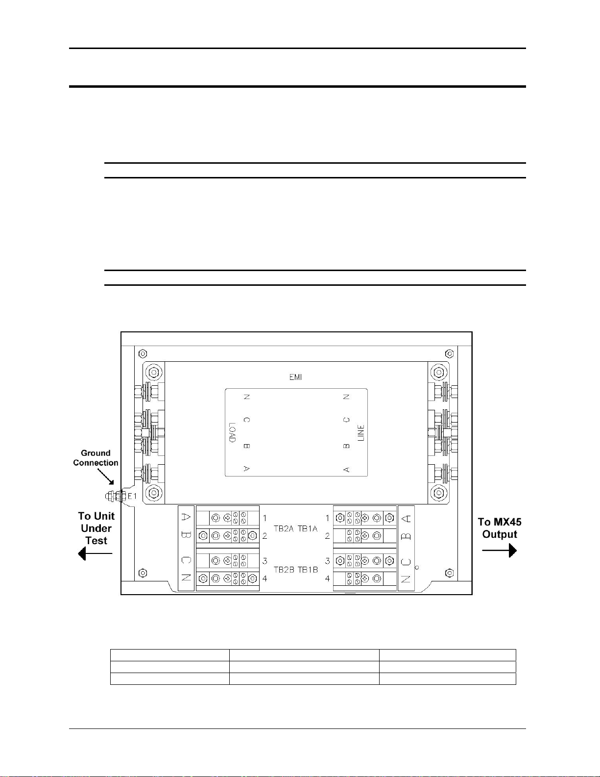
User Manual – Rev AJ California Instruments
3.14 Ou ccestput Filter Box A sory
An optional output filter box (P/N 7003-424-1) is available which may be used reduce the
amount of ripple and noise present at the output of the MX30/45-3Pi.
The filter must be connected between the three-phase output of the MX30/45 and the unit under
test. To access the connection terminal blocks, the top cover of the filter case must be removed.
Note: Make sure all power is off when connecting the filter accessory.
The output of the MX30/45 is connected to the input side of the filter. Use terminal blocks TB1A
(phases A and B) and TB1B (phase C and neutral) as indicated in Figure 3-21. The load can be
connected to the load side of the filter box using terminal blocks TB2A and TB2B. Do not swap
phases through the filter.
To compensate for voltage drop across the filter, the external sense connections can be made
at the load (load side of the filter).
Note: The filter box chassis must be connected to earth ground.
It is not recommended to use the ground connection on the MX30//45 itself for this purpose but
rather a ground point at the AC service to the MX30/45.
Figure 3-21: 7003-424-1 Output noise filter box.
Dimensions 7003-424-1:
W x L x H Chassis 12.125 “ x 16.125” x 4.125” 308 x 410 x 105 mm
Feet height: 0.875 22 mm
Strain relief hole size: 1.5” diameter 38 mm diameter
72 MX Series
Page 73

User Manual – Rev AJ California Instruments
3.15 Fuse Box Accessory
An Output Fuse Box (P/N 7003-426-1) is provi
cabinets. This fuse box prov
amplifiers in different chassis in case of a system malfunction.
Each fuse is capable of sustaining up to 125 Arms of AC current, which is the maximum
available current per MX amplifier.
Each fuse box has 9 sets of 3 fuses for phase A, phase B and phase C. Each fuse terminal is
lined up with a strain relief on each side of the box. The outputs from the MX45 cabinets connect
to the “MX 45 SOURCE” side of fuse box. The outputs of the fuse box (marked “JUNCTION
BOX” are normally routed to the 7003-416-1 Junction box (marked “MX SYSTEM OUTPUT”)
where the outputs of the various cabi
connected to the “LOAD” side of the junction box.
Note: The Fuse box enclosure must be connected to Earth ground using the provided
ground stud.
ides protection against excessive current circulating between
nets are combined for each phase. The load can then be
ded with MX systems consisting of more than 2
Figure 3-22: 7003-426-1 Output Fuse Box
Dimensions 7003-426-1:
W x L x H Chassis 12.125 “ x 16.125” x 4.125” 308 x 410 x 105 mm
Feet height: 0.875 22 mm
Strain relief hole size: 1.5” diameter 38 mm diameter
MX Series 73
Page 74

User Manual – Rev AJ California Instruments
4. Front Panel Operation
4.1 Tour of the Front Panel
The MX Series with type P or type Pi have identical front panels although some of the keys
found on the front panel are only
type controller, these keys will a
the MX with either controller type
used by MX models with the 3Pi controller. If your unit is a P
ct as don’t cares. This chapter provides information on operating
.
Before operating the AC source
front panel controls. Specifically,
covered in the next few paragrap
4.1.1 Front Panel Controls and Indica
The front panel can be divided in a small number of functional areas:
Mains circuit breaker
Status Indicator lights
Shuttle knob
LCD display
FUNCTION keypad
DATA E
4.1.2 System On/Off Circuit Breaker
The circuit breaker located on the bottom left side of the front panel disconnects the low voltage
supply of the MX Source from the three phase Line input. This will remove power from the mains
AC input contactor and thus remove input power from the MX Series power source. As such,
the circuit breaker acts as an indirect power on/off switch for the MX Series unit. Note however
than AC input power remains applied to the primary side of the input transformer.
NTRY keypad
using the front panel, it helps to understand the operation of the
the operation of the knob, keyboard and the menu layout are
hs.
tors
When the input current rating of the MX Series AC power source is exceeded, the protective
fuses (F1 through F3) will blow. In this case, power to the low voltage supply may still remain
through the front panel circuit breaker. In this case, the on/off circuit breaker should be opened
(power off) first followed by a complete disconnect of all ac input power through an installed
main circuit breaker.
Note that in MX60, MX90 and MX135 systems, each unit has its own on/off circuit breaker and
set of line input fuses.
74 MX Series
Page 75

User Manual – Rev AJ California Instruments
4.1.3 Status Indicator Lights
Four LED status indicators are located directly above the mains circuit breaker. These LED’s
correspond to the following conditions:
REMOTE The REMOTE LED indicates that the unit is in remote control
mode. If the IEEE-488 interface is used, this indicator will be lit
whenever the REM line (REMOTE ENABLE) line is asserted by
the IEEE controller. If the RS232, USB or LAN interface is used,
the REMOTE state can be enabled by the controller using the
SYST:REM command. Any time the REMOTE LED is lit, the
front panel of the MX Series unit is disabled. There is no
LOCAL button that allows the user to regain control of the front
panel. This prevents accidental change of settings in ATE
applications.
OVERLOAD The OVERLOAD LED indicates an output overload condition.
This condition can be controlled by setting the current limit
value in the PROGRAM menu. Removing the load usin
g the
OUTPUT ON/OFF button will recover from an overload
condition.
OVER TEMPERATURE The OVER TEMPERATURE LED indicates an overheating
problem inside the unit. This is an abnor
mal condition, which
will cause the unit to shut off. Check the air openings to make
sure they are not blocked.
HI RANGE The HI RANGE LED is on when the high voltage output range
has been selected.
MX Series 75
Page 76

User Manual – Rev AJ California Instruments
4.1.4 The Shuttle Knob
Counter
Clock
wise
Clock
wise
INCRDECR
Figure 4-1: Shuttle Knob
The shuttle knob is located to the right of the LCD screen and is used to change setup
parameters. Note that it cannot be used to move the cursor position between menu fields. Use
the UP and DOWN arrow keys in the FUNCTION keypad for this.
The shuttle knob can operate in
MODE DESCRIPTION
IMMEDI Any time the ENTER key is pressed, the MX Series returns to
ATE mode
one of two distinct modes of operation:
its normal mode of operation. In this mode, changes made with
the shuttle knob or the data entry keypad will take immediate
effect. The IMMEDIATE mode is useful for slewing output
values such as voltage and frequency and observing the effec
on the load.
t
SET mode
When the SET key located in the FUNCTION keypad is
pressed, changes made with the shuttle to any output
parameter will not take effect until the ENTER key is pressed. In
this mode, any changes made to a setup menu will be blinking
to indicate the pending change condition. This mode allows
changes to be made to all output parameters and executing
them all at once by pressing the ENTER key.
76 MX Series
Page 77

User Manual – Rev AJ California Instruments
4.1.5 FUNCTION Keypad
The function keypad provides ac
keys are located in the FUNCTIO
cess to all menus and measurement screens. The following
N keypad:
FUNCTION
MENU PROG WAVE MEAS
OUTPUT
ON/OFF
Figure 4-2: FUNCTION Keypad
KEY DESCRIPTION
MENU The top level menu is accessed by pressing the MENU key.
Three shortcut keys are used to provide direct access to the
PROGRAM, WAVEFORM, and MEASUREMENT screens as
these are among the most frequently used screens. Thus,
instead of going through the main menu to reach the
PROGRAM, WAVEFORM, and MEASUREMENT screens, they
can be accessed directly by pressing the PROG, WAVE, and
MEAS keys respectively. A map of the Main menus is provided
on the next few pages. There are three top level menus in the
MX Series.
PHASE
SET
+/-
PROG The PROG key is a shortcut to access the PROGRAM menu
directly. The PROGRAM menu is one of the most frequently
used menus. Thus, instead of going through the main menu to
reach the PROGRAM menu, it can be accessed directly by
pressing the PROG key.
WAVE The WAVE key is a shortcut to access the WAVEFORM screen
directly. The WAVEFORM screen is used to select a user
defined arbitrary waveform. (3Pi controller only)
MEAS The MEAS key is a shortcut to access the MEASUREMENT
screen directly. The MEASUREMENT screen is one of the most
frequently used screens. Thus, instead of going through the
main menu to reach the MEASUREMENT screen, it can be
accessed directly by pressing the MEAS key.
MX Series 77
Page 78

User Manual – Rev AJ California Instruments
OUTPUT ON/OFF The OUTPUT ON/OFF key toggles the output relay on or off.
The state of the output relay is reflected by the green LED
located directly to the left of the OUTPUT ON/OFF key. If the
green LED is lit, the output relay is enabled (closed) and the
programmed output voltage is present at the output terminal
s. If
the green LED is off, the output relay is open and both the
HIGH and LO terminal of the output term
inal block are
disconnected from the power source. In this mode, the output is
floating. The ON/OFF button provides a convenient way to
disconnect the load without having to remove any wires.
PHASE The PHASE key is used to select the phase on a MX30-3Pi or
MX45-3Pi model. Pressing the PHASE key will toggle phase A,
B, C or ABC. Some screens may not support the ABC or show
all phase information in which case this mode is skipped. (3Pi
controller only)
SET The SET key is used to select the mode of operation of the
shuttle. Refer to section 4.1.1 for details on its operation and
the use of the SET key.
+/- The +/- key can be used to toggle the sign for those parameters
for which it is relevant. This is typically the output voltage when
in DC mode of operation. For fields that have only two possible
values such as the voltage range field, the +/- key can be used
to toggle between these two values.
78 MX Series
Page 79

User Manual – Rev AJ California Instruments
4.1.6 DECIMAL KEYPAD
The decimal keypad may be used to enter any numeric parameter required in any of the men
fields. Several fields accept input from either the keypad or the knob. Data entered from the
keypad is normally accepted once the ENTER key is pressed unless the front panel mode is in
the SET mode. The following keys are available on the decimal keypad:
u
ENTRY
7
45
123
89
6
E
N
T
E
.0
R
Figure 4-3: Entering Values from the Decimal Keypad
CURSOR UP The UP key moves the cursor position upwards one position
the previous available cursor position. If the present curs
position is at the top of the right hand column, the cursor is
moved to the bottom position of the left hand column. If the
present cursor is at the top of the left hand column, the cursor is
moved to the bottom of the right hand column. Figure 4-4
depicts the cursor movement through a two column menu.
Figure 4-4: Cursor UP Key Movement
CURSOR DOWN The DOWN key moves the cursor position downwards one
position to the next available cursor position. If the present
cursor position is at the bottom of the left hand column, the
cursor is moved to the top position of the right hand column. If
the present cursor is at the bottom of the right hand column, the
cursor is moved to the top of the left hand column. Figure 4-5
depicts the cursor movement through a two-column menu.
or
to
MX Series 79
Page 80

User Manual – Rev AJ California Instruments
Figure 4-5: Cursor DOWN key Movement
The decimal keypad can be used at any time in lieu of the shuttle knob to change output
parameters. Direct data entry is often faster to effect large changes in values than using the
shuttle knob. N
ote that pressing the ENTER key while in SET mode of operation will cause the
AC source to revert back to IMMEDIATE mode. Thus, to change all parameters in SET mode,
enter a value for each field and then proceed to the next field without pressing the ENTER key.
0 through 9. The numeric keys provide all decimal number for entry of
parameters.
DECIMAL POINT The decimal point key is used to enter fractional parts of values
for fields that have a resolution less than 1. The amount of
resolution for each menu field is normally visible on the LCD. If
more digits are entered after the decimal point than can be
accepted by a field, the value is automatically rounded to the
available resolution when the ENTER key is pressed.
4.1.7 L
BACKSPACE The BACKSPACE () key can be used to erase one digit at a
time if you make a data en
try error.
CD Display
The LCD display of the MX Series power source provides information on instrument settings and
also guides the user through the various menus. To ease reading of the displayed information,
most screens are widely spaced. A sample of the main menu 1 screen that appears when the
MX Series source is powered up is shown in Figure 4-6. Due to the amount of space available
on each screen, some menus have been split into parts. The MORE selection located at the
bottom right hand side provides access to menu choices at the same level that did not fit on a
single screen. Thus, to access MENU 2, the cursor should be placed on the ‘MORE’ selection
followed by pressing the ‘ENTER’ key. Alternatively, the MENU key may be pressed to move to
the MENU 2 screen.
The present cursor position is always shown with a inverse bar. The cursor is located on the
‘MORE’ selection in Figure 4-6. Pressing ENTER would cause MENU 2 to be displayed.
The cursor position can be moved by using the UP and DOWN keys located in the DECIMAL
keypad.
Figure 4-6: Main Menu 1 Screen
80 MX Series
Page 81

User Manual – Rev AJ California Instruments
4.2 Menu Structure
The next few pages show a map of the available menus in the MX Series. There are three main
level (level 1) menus from which all other menus can be reached. Frequently used (level 2)
menus have a short cut key that provides di s. Examples of such menus are Program,
Measurements, and Waveform. In any case, there are never more than three levels of me
although some menus may be spread across more than one screen.
rect acces
nus
4.2.1 MAIN
The top-level menu is split in thr
menu entries. MENU 2 and 3 can be reached from MENU 1 by selecting the MORE entry or by
pressing the MENU key repeatedly, which will toggle from MENU 1 to 2 to 3 and back to 1. Th
division of menu choic n the two screens is graphically illustrated in 4.2.2 by the boxes
in level 1. Each box represents one screen.
MORE entry.
Menus
F
igure 4-7: Menu 1 through 3
ee parts, MENU 1 through MENU 3 to allow spacing between
e
es betwee
Subsequent screens can be reached using the
MX Series 81
Page 82

User Manual – Rev AJ California Instruments
The following top-level menu choices can be accessed from the MENU key:
Description Entry
MENU 1
PROGRAM The PROGRAM menu allows output parameters the be
changed.
MEASURE The MEASUREMENTS screens are not menus in that no user
MENTS
entries are required.
TRANSIEN The TRANSIENTS menu allows output transients to be
TS
programmed.
WAVEFORMS
The WAVEFORMS menu allows different waveforms to be
selected from the waveform library.
MORE The MORE selection causes the second part of the MENU
screen to be displayed. (MENU 2)
MENU 2
ADVANCED The ADVANCED MEAS. screens are for display only. No user
MEAS.
entries are required.
APPLICATI The APPLICATIONS menu provides access to the optional
ONS
firmware application programs that may be installed in the MX
Series AC source.
SETUP REGISTERS The SETUP REGISTERS menu allows complete instrument
settings and transient list programs to be saved to nonvolatile
memory.
MORE The MORE selection causes the third part of the MENU screen
to be displayed. (MENU 3)
MENU 3
UTILITY The UTILITY menu provides o less nly us
s screens those PIB a 2C (
etup such as for the G nd RS23 also
access t commo ed
applies to USB and LAN) interface settings, initial startup
values, etc.
OUTPUT IMPEDANCE The OUTPUT IMPEDANCE m l of the
source output impedance. X30-3Pi or M
enu provides contro AC
(M X45-3Pi model
only)
MEASUREMENT CAL The MEASUREMENT CAL menu allows for calibration of the
AC source measurement system.
OUTPU AL
T C The OUTPUT CAL menu allows for calibration of the AC source
output.
Following the Menu overview pages is a detailed description of each menu and sub menu.
82 MX Series
Page 83

User Manual – Rev AJ California Instruments
4.2.2 Overview of Menu 1
level 1
MENU 1 M
PROGRA ROGRAM1
MEASUREMENTS
TRANSIENTS
WAVEFORMS
MORE
level 2 level 3
P
VOLTAGE
FREQ
VOLT RANGE
CURR LIMIT
MORE
PROGRAM
PHASE
CLOCK MODE
DE VOLT MO
DC OFFSET
START ø
MEASUREME
VOLTAGE
CURRENT
FREQ
POWER
MORE
MEASURE
VA POWER
PEAK CURR
POWER FACT
CREST FACT
PEAK CURR RESET
MEAS 3
VOLT THD
CURR THD
INST PK CURR
PHASE
HARMONICS/TRA
N FUNCTIO
VIEW
DATA MODE
SCALE
TRIG MODE
TRIG SOURCE
TRIG PHASE
TRIG DELAY
START
VOLT SURGE/SAG START ø
STEP START ø GO TO VOLT VOLT SWEEP/
STEP END VOLT DUR SCALE FREQ SWEEP/ DURATION
EP DURATION DURATION VOLT/FREQ SWEEP/ST END FREQ DUR SCALE
QUENCE T END VOLT DURATION END VOLT START/VIEW SE STAR END DELAY
EVIOUS SCREEN END FREQ NCTION END DELAY END DELAY PR PAUSE FU
AT #0 END DELAY PEAT FUNCTION FUNCTION REPE RE
CLEAR FUNCTION ENT# REPEAT REPEAT SEQ EV
REPEAT EVIOUS SCREEN EVENT# EVENT# PR
SEQUENCE# EVIOUS SCREEN PREV. SCREEN #1 PR
#2 PREVIOUS SCREEN
..
#98
#99
REEN PREVIOUS SC
LEVEL CLIP
GROUP
MODE
SINE
SQUARE
CLIPPED
USER WAVE
..
..
USER WAVE
MENTS 2
UREMENTS
ANALYS
2
NTS1
IS
CE
MX Series 83
Page 84

User Manual – Rev AJ California Instruments
4.2.3 Overview of Menu 2 and 3
level 1
MENU 2 ADVANCE
MEAS.
FUNCTION
APPLICA
TIONS
SETUP
REGISTERS
MORE
MENU 3 UT ILITY
OUTPUT
IM
PEDANCE
ME
ASUREMENT
C AL
OUTPUT CAL
level 2 level 3
HARMONICS/TRACE
ANALYSIS
VIEW
DATA MODE
SCALE
TRIG MOD E
TRIG SOURCE
TRIG PHASE
TRIG DELAY
START
APPLICATIONS SETUP 1
NORMAL STATE PREVIOUS SCREEN ABNORMAL OMNI OPTION
S EMERGENCY EMERGENCY RTCA-DO160D IEC 1000-4-13 TESTS IEC 1000-4-11 TEST
APPLICATIONS SETUP 2 RUN VOLT VARIATIONS PREVIOUS SCREEN PREVIOUS SCREEN
IEC 1000-4-13 CLASS PREVIOUS SCREEN
WH METER GROUP
DWELL
SAVE REGISTER # LEVEL
VIEW/EDIT REG # FRANGE
RECALL REGISTER # STEP
PREVIOUS SCREEN IHFREQ
UTILITY 1
GPIB/RS232 SETUP
PREVIOUS SCREEN OL MODE RS232 DATA
INITIAL SETUP VOLTAGE TRIP DELAY RS232 PARITY
LIMIT SETUP RS232 STOPBITS VOLTAGE CUR LIMIT VOLT SENSE
MORE REVIOUS SCREEN CUR LIMIT PREV. SCREEN NO. OUTPUT P
UTILITY 2
CONFIGURATION CONFIG SETUP 1 FREQ HI PHASE
LANETWORK SETUP MORE HH:MM:SS NO. OUTPUT PHASE C
ELAPSED TIME ATURE ADVANCE PREVIOUS SCREEN VOLT RANGE TEMPER
VIEWING ANGLE DO160 VOLT MODE
PREVIOUS SCREEN MIL704 OL MODE
CONFIG SETUP 2 OUTPUT RELAY
IEC 4-11 MORE
IEC 4-13 VOLT SENSE
CLOCK/LOCK WAVE GROUP
WH METER CLOCK MODE
RESISTIVE PUT CONFIG SETUP 3
UCTIVE
IND MS704 VOLT ALC
MINIMUM SET ABD PREVIOUS SCREEN
LF
SYSTEM
MB
Series II only Series I only
FS
VOLT VOLT FS
CURR FS VOLT 0
EVIOUS SCREEN PR VOLT FS HT
VOLT FS 0
CURR FS
CURR 0
CURR FS HT
CURR 0 HT
PREVIOUS SCREEN
Series II only Series I only
VOLT FS VOLT FS
VOLT ZERO V HI-FREQ
PHASE OFST VOLT ZERO
IHARM FS PHASE OFST
IMP. REAL FS IMP. REAL FS
IMP. REACT FS IMP. REACT FS
IMP. REAL MIN IMP. REAL MIN
IMP. REACT MIN IMP. REACT MIN
PREVIOUS SCREEN PREVIOUS SCREEN
FREQ LO FREQ PREV. SCREEN
1
NO. OUT
STEADY STATE
TRANSIENTS MIL-STD 704 MODE
ALL MIL704 TESTS IEC 1000-4-11 STATE DIPS AND INTER. ABNORMAL
RESONANT
GPIB ADDRESS
VOLT ALC RS232 BAUDRATE VOLT/CURR CONTROL
1
CONFIGURATION SETUP 3 menu available on Series II models only.
84 MX Series
Page 85
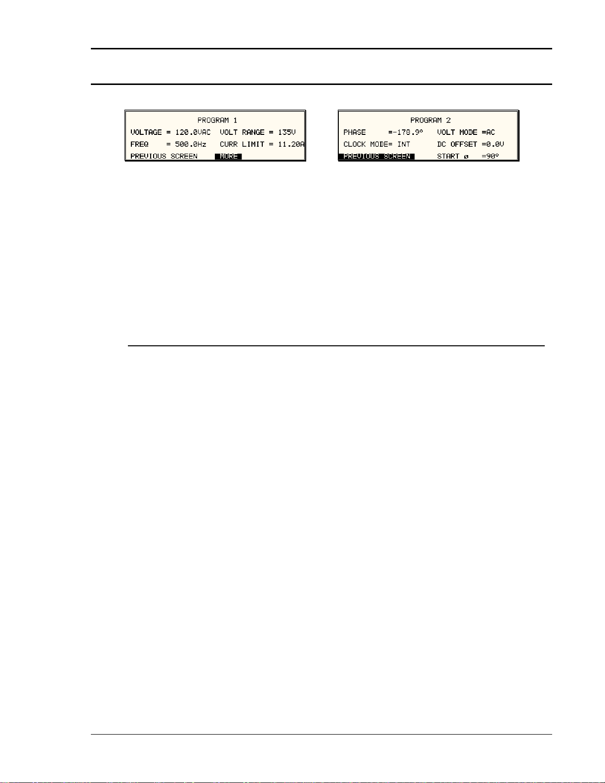
User Manual – Rev AJ California Instruments
4.2.4 P ROGRAM Menu
igure 4-8: PROGRAM Menu F
The PROGRAM menu is shown in Figure 4-8. It can be reached in one of two ways:
1. by selecting the PROGRAM
2. by pressing the PROG key i
The PROGRAM menu is used to
entry in the MENU screen and pressing the ENTER key
n the FUNCTION keypad
change output parameters. The most commonly used
parameters are all located in PROGRAM 1. The PREVIOUS SCREEN entry, when selected, will
return the user to the most recently selected menu. This is normally the MENU screen unless
the PROGRAM menu was selec
frequently used parameters are
PROGRAM 1 screen using the M
ted using the PROG key on the FUNCTION keypad. Less
located in PROGRAM 2, which can be reached from the
ORE selection, or by pressing the PROGRAM key twice.
The following choices are available in the PROGRAM menus:
Entry Description
PROGRAM 1
VOLTAGE Programs the output voltage in Vrms while in AC mode or
absolute voltage when in DC mode. In DC mode, negative
values can be entered.
FREQ Programs the output frequency when in AC mode. If the unit is
in DC mode, the value for FREQ will be set to DC and cannot
be changed until AC mode is selected. When in AC mode, the
frequency can be changed from 16 Hz to 500 Hz. Values
entered that fall outside this range will generate a -200 RANGE
ERROR and will not be accepted.
VOLT RANGE Selects 150V, 300V or optional 400V range in AC mode and
200V or 400V range in DC mode. The actual range values may
be different depending on the configuration. The value of this
field can only be changed with the shuttle or the +/- key.
CURR LIMIT Sets the current limit value for the current detection system.
When the load current value exceeds the set current limit, a
fault condition is generated. The actual response of the AC
Source to a current limit fault is determined by the protection
mode selected in the CONFIGURATION menu. (CC = Constant
Current, CV = Constant Voltage).
PROGRAM 2
PHASE Selects the phase angle between the external clock and the
output of the AC source. If the clock source is internal, this
parameter has no effect.
MX Series 85
Page 86

User Manual – Rev AJ California Instruments
CLOCK MODE Selects internal or external clock source. The MX Series
controller uses an open-air crystal time base with an accuracy
of 100 ppm. To improve output frequency stability and
accuracy, an external clock generator may be used.
VOLT MODE The MX Series offers three output modes, AC, DC and AC+DC.
The VOLT MODE field can be used to toggle between the
se
three output modes. Both the Knob and the +/- key may be
used to toggle through these three selections. In DC mode, no
frequency selection is possible and all maximum current and
power ratings are divided by two.
DC OFFSET When the AC+DC mode is selected, the VOLTAGE field in the
PROGRAM 1 screen is used to set the AC portion of the output
voltage. The DC OFFSET field in the PROGRAM 2 screen can
be used to set the DC offset level. Either the knob or the
decimal keypad may be used to set the DC offset level.
START ø made to either
Selects the start phase angle for output changes
voltage or frequency. This allows changing the output at a
specific phase angle. The output on key also uses this phase
angle setting to program the output voltage up to the set level
after the output relay is closed. The default value for this field is
RANDOM.
86 MX Series
Page 87

User Manual – Rev AJ California Instruments
4.2.5 MEASUREMENTS Screens
The MX Series uses a DSP bas
regarding the output of the Sour nt
waveforms and calculates sever
calculations is displayed in a ser
ed data acquisition system to provide extensive information
ce. This data acquisition system digitizes the voltage and curre
al parameters from this digitized data. The result of these
ies of measurement data screens. The actual digitized
waveforms can also be displayed by selecting the Harmonics/Trace Analysis screen. A total of
four measurement screens are used to display all this information (3Pi controller o
nly).
Figure 4-9: MEASUREME
The first three Measurement scr
changes can be made anywhere adouts.
The fourth measurement screen
several user accessible fields (P
successively pressing the MEAS all four available screens.
NTS Screen, Single Phase and Three Phase Modes
eens available on the MX Series are not menus in that no
. Instead, these three screens provide load parameter re
provides access to the advanced measurements and does offer
i controller only). The measurement screens can be reached by
key, which will toggle to
In three-phase mode, measurements are available for each phase individually. To select the
desired phase, use the PHASE
displays the data for all three ph
The following parameters are av
key to toggle through phase A, B, C, or ABC. The ABC mode
ases simultaneously.
ailable in the first three measurement screens:
Entry
Description
MEASUREMENT 1
VOLTAGE When in AC or AC+DC mode, this value is the true rms outp
voltage measured at the voltage sense lines. In DC only mode,
the voltage is the DC voltage including polarity.
CURRENT
When in AC or AC+DC mode, this value is the true rms output
current drawn by the load. In DC only mode, the current is the
DC current including polarity
FREQ tput frequency is
When in AC or AC+DC mode, the ou
measured at the sense line
s. When in DC only mode, this value
always reads “DC”.
POWER In both AC and DC mode, this value is the real rms. power
consumed by the load.
MEASUREMENT
2
VA POWER In AC or AC+DC mode, this value is the apparent rms. power
consumed by the load. In DC m
ode, this value is always the
same as the POWER readout.
ut
MX Series 87
Page 88

User Manual – Rev AJ California Instruments
PEAK CURR This readout reflects the peak current value detected at the
output. To measure inrush current for a unit under test, open
the output relay and reset the peak current value using the
PEAK CURR RESET entry. Then program the output voltage
and frequency and turn on the output relay. The peak curren
t
measurement will continuously track the maximum current
value detected until reset.
POWER FACTOR This readout shows the power factor of the load.
CREST FACTOR This readout displays the ratio between peak current and rms
current.
MEASUREMENT 3
VOLT THD This readout displays the total voltage distortion for the se
[3Pi controller only]
lected
phase. The distortion calculation is based on the H2 through
H50 with the fundamental voltage (H1) in the denominato
t on defi the
hat other comm
v nomin
oltage as the de
nitions of THD use the RMS value of
ator. This may result in different
r. Note
readings between instruments depending on the
implementation chosen. The mode used by the power source is
selectable over the bus.
CURR THD This readout displays the total current distortion for the selected
phase. The distortion calculation is based on the H2 through
H50 with the fundamental current (H1) in the denominator. Note
that other common definitions of THD use the RMS value of the
current as the denominator. This may result in different
readings between instruments depending on the
i n chosen e is
mplementatio . The mode used by the power sourc
selectable over the bus
.
INST PK CURR This readout reflects the instantaneous peak current value
detected at the output. This value is updated continuously and
does not require a reset operation like the PEAK CURR
readout. The instantaneous peak current does not use a track
and hold mechanism like the PEAK CURR measurement in the
M 2 scr nt
EASUREMENT een. Instead, it tracks the peak curre
on a cycle-by-cycle bas cks
is. The INST PK CURR typically tra
the rms current and the crest factor.
Update Program Functions from Measurement Screen
The Shuttle can be used to update program parameters such as voltage, frequency or current
from the measurement screen. This can be achieved with the following sequence:
1. Select the program 1 screen using the PROG key.
2. Use the up and down key to
will be changed by the shutt
select the desired function to update. (Selects parameter that
le once in the MEAS1 screen)
3. Select the measurement 1 screen by pressing the MEAS key.
. The pointer symbol (X) poin
4 ts to the programmed parameter (V, F or CL) that will be
affected by turning the shutt
le.
88 MX Series
Page 89

User Manual – Rev AJ California Instruments
HARMON S Screen [3Pi controller only]
The fourth measurement screen
MX Series with 3Pi controller on
Harmonics/Trace Analysis meas
accessible fields. These fields a
mode. The actual data is display on
ICS/TRACE ANALYSI
is dedicated to the advanced measurements available on the
ly. This screen is not available on the P controllers. The
urement screen is a true menu screen offering several user
re used to select the desired acquisition trigger and display
ed whenever the ENTER key is pressed while the cursor is
the VIEW or START field. The following fields are available on this menu:
Figure 4-10: H
Entry
ARMONICS/TRACE ANALYSIS Screen
Description
FUNCTION Selects Voltage, Current or Both parameters for display.
VIEW
Available display modes are TABLE, BAR and TRACE.
TABLE mode: Displays the first 50 harmonics in a
tabular text format.
BAR mode: Displays the first 50 harmonics in a
graphical bar chart display.
TRACE mode: Displays the selected Function in
time domain (waveform) graphi
a
cal
display.
MX Series 89
Page 90

User Manual – Rev AJ California Instruments
DATA MODE
Selects absolute or relative harmonics display for TABLE and
BAR view mod
es. In relative mode, all harmonics are shown in
a percentage of the fundamental, which is normalized at 100 %
In absolute mode, the harmonic amplitudes are shown in
absolute volts or amperes.
nd
This mode does not apply to the TRACE view display mode a
is ignored when this mode is selected.
SCALE
Sets the horizontal time axis for the TRACE view display mode.
The field range is:
Series I: 4 ms to 104 ms in single-phase mode (MX30-3P
i or
MX45-3Pi only) or 12 ms to 312 ms in three phase mode.
Series II: 4 ms to 42 ms in single-phase mode (MX30-3Pi or
MX45-3Pi only) or 12 ms to 128 ms in three phase mode.
This parameter is ignored when the TABLE or BAR view display
mode is selected.
TRIG MODE
This field sets the trigger mode for the acquisition. Available
options are SINGLE (single shot acquisition) or CONT
(continuous acquisition). In SINGLE shot mode, the acquisition
is triggered once each time the S
TART field is selected and the
ENTER key is pressed. The selected trigger source is used to
determine the trigger point. Once the acquisition has been
triggered, the data are displayed and do not change until the
next acquisition is triggered. This mode is most appropriate for
single shot events such as start up currents.
.
In the CONT mode, acquisitions occur repeatedly and the data
is updated on screen after each trigger occurs. This provides a
continuous update of the data and is most appropriate for
repetitive signals.
TRIG SOURCE The trigger source selects the event that will trigger a
measurement acquisition. Available options for this field are
IMM (immediate), PHASE A or SET VOLT. The IMM trigger
source causes the acquisition to trigger immediately when the
ENTER key is pressed on the START field. Essentially, this is
an asynchronous trigger event. The acquisition will always be
triggered in this mode and data is available immediately.
The PHASE A source will cause the acquisition to trigger on the
occurrence of a set phase angle for the voltage on phase A.
The trigger source is always phase A when in this mode,
regardless of the phase selection shown in the top right corner
of the display. When the acquisition is started, the acquisition
system waits for the specified phase angle to occur before
triggering the acquisition. This mode allows exact positioning of
the acquisition data window with respect to the voltage
waveform.
The SET VOLT mode causes the acquisition to trigger at the
specified voltage. This mode also programs the selected phase
or all three phases when the measurement is started from the
START field. As such, this trigger source selection also
programs the output voltage to the selected rms level.
TRIG PHASE / SET VOLT This field changes purpose, depending on the trigger source
selected immediately above it. If the trigger source equals IMM
90 MX Series
Page 91

User Manual – Rev AJ California Instruments
or PHASE A, this field can be used to program the trigger
phase angle (TRIG PHASE). In IMM mode, the value of this
field is ignored.
If the trigger source is set to SET VOLT, this field can be used
to specify the rms voltage to program the output to and trigger
the measurement on. The v
exceed the maximum voltage range selected or the r
capability for the wave shape selected on the phase
oltage value set here should not
ms
or phases
programmed.
TRIG DELAY ield allows the trigger point to be positioned
The trigger delay f
anywhere in the acquisition window. A negative value will
provide pre-trigger
information on data leading up to the trigger
event. The pre-trigger delay cannot exceed the length of the
acquisition buffer. See paragraph 4.6.3.3 for details. A positive
trigger delay positions the data window after the trigger event.
Positive trigger delays can exceed the length of the acquisitio
n
buffer in which case the trigger event itself will not be in the
buffer a
1000 ms. The default trigger de
ny more. The maximum value of the trigger delay is
lay value is 0.0 ms, which puts
the trigger event at the beginning of the acquisition window.
START The START field is used to start a new acquisition run. To start
an acquisition, place the cursor on the START field and press
the ENTER key. Once the ENTER key is pressed, the display
toggles to the data display mode selected in the VIEW field
as
soon as the selected trigger event occurs. To return to the
HARMONICS/TRACE ANALYSIS menu, press the ENTER ke
while in the data display mode.
out triggering a new acquisition,
To change display modes with
make the desired changes in the menu and move the cursor to
the VIEW field. Once on the VIEW field, press the ENTER key.
This will not trigger a new acquisition, which means the origina
data is retained.
y
l
MX Series 91
Page 92

User Manual – Rev AJ California Instruments
4.2.6 TRANSIENTS Menu
Figure 4-11: TRANSIENTS Menu
The transient menu provides access to the transient list data. Available list length is:
Series I: Both P and Pi controllers; 32 data points. This is represented by
32 transient
step numbers from 0 through 31.
Series II: Both P and Pi controllers; 100 data points. This is represented by 100 transient
step numbers from 0 through 99.
From the Transient menu, the desired transient step type can be selected. Based on the user’s
choice, the relevant transient type sub menu will be shown. The START/ED
menu allows the user to review and change any transient
When executing a transient list, transient steps are execu
step or execute the transient list.
ted in a ascending numerical order.
IT SEQUENCE sub
Steps that are not defined are skipped.
The following entries can be fou
Entry
VOLT SURGE/SAG
nd in the TRANSIENTS menu:
Description
Voltage surges and sags are temporary changes in amplitude.
The output voltag
e will change from its present value to a user
specified value for a specified duration. (Sag if the value is
lower, surge if the value is higher.) After this period has expired,
the outp
ut voltage returns to a user specified end value. This
value may or may not be the same as the value present prior to
the start of the sag or surge.
VOLT SWEEP/STEP
Voltage sweeps cause the output voltage to change from the
present value to a user specified end value at a specified rate of
change. A voltage step on the other hand is an instantaneous
change in output voltage. The new value will be held for the
duration period specified by the user. The final output voltage
value of a sweep and a ste
p transient step should be different
than the value at the start of the transient step or no change in
output value will occur.
FREQ SWEEP/STEP e sweep/step except it
This transient type is similar to a voltag
affects the frequency. Refer to the previous paragraph.
VOLT/FREQ SWEEP/STEP to a
This transient type combines the previous two types in
single step. The effect is that of changing the output voltage
and frequency simultaneously.
is programmed as a single transient
Note: While this transient
step, two list entries are required to store this information. As
such, every VOLT/FREQ SWEEP/STEP used will consume two
list entries at a time.
92 MX Series
Page 93

User Manual – Rev AJ California Instruments
START/VIEW SEQUENCE This entry allows the user to switch to the transient execution
menu. This menu provides a list of all available transient list
steps and their sequence numbers. From this menu, transient
list execution can be started.
4.2.6.1 RGE/SAG sub menuVOLT SU
Figure 4-12: V
The Voltage surge and sag scre
screen as follows:
1. Scroll to the VOLT SURGE/
2. Press the ENTER key to bring up the VOLT SURGE/SAG screen.
The VOLT SURGE/SAG screen has several data fields. All data fields that are blank to the right
of the equal sign must be filled or an error message will occur when trying to leave this screen.
The EVENT # is the last data field to be filled. Entering the event data field will cause the display
to return to the TRANSIENT screen where a new selection can be made.
The VOLT/SURGE/SAG screen has the following fields:
START ø This field will show the start phase angle of the voltage transient
The same menu can be used to view or edit any available
transient list step or erase a step using the backspace key.
OLTAGE SURGE/SAG SETUP Screen
en shown in Figure 4-12 can be reached from the transient
SAG entry using the up and down cursor keys.
in degrees. Only one start phase angle per transient sequence
is allowed. The start phase angle must be in the first transient
event in the list. The start phase angle is not valid for DC
transients. If no start phase angle is required, this field can be
set to RANDOM by pressing the BACKSPACE (<-) key on the
decimal keypad.
GO TO VOLT This field will set the voltage level during the transient duration
in volts
DUR SCALE Duration scale default is time in seconds. Use the Shuttle knob
to select CYCLES if desired. Note that durations expressed in
cycles may cause rounding errors if the period of the selected
frequency setting is not an integer number of mss. Thus, for 50
Hz applications, no rounding errors occur but for 60 Hz, the
16.66¯ ms period will cause a rounding error when converted.
The Duration scale selection affects both the DURATION and
END DELAY parameters.
DURATION Duration is the time the output voltage level will dwell at the GO
TO VOLT level. The DUR SCALE defines the time scale of this
parameter in CYCLES or SECONDS
END VOLT This is the output voltage level at the end of the transient
EVENT and after a time specified by the DURATION
MX Series 93
Page 94

User Manual – Rev AJ California Instruments
END DELAY This is the time delay the voltage level will stay at the END
VOLT
level before it proceeds with the next transient event or
completes the transient.
FUNCTION [3Pi controller only] This field can be used to select the wave
shape to be used during this step of the transient sequence.
Each step can use a different wave sh
ape from the available
library of 50 user-defined waveforms or the three standard
waveforms. The output wave shape changes upon entry into
each step and remains in effect for the duration of the step. The
default wave shape is always the SINE (s
ine wave).
REPEAT This is the number of times the SURGE/SAG
will repeat before it will proceed to the next event or exit the
transient program. Note that the number of times the transient
event is generated is equal to the REPEAT + 1. Leave this
value at zero if only one execution of this event in the list is
required.
EVENT # This must be the last item in th
e transient edit screen. All data
fields must be entered before inserting the EVENT #. The
EVENT # takes a value from 1 to 99. The EVENT # defines the
order of execution of the transient events in a multiple event
transient. It is a good practice to enter spaced EVENT #’s
allow inser
tion of an EVENT later if needed. (For example,
space them by 5.) Entry of a sequence EVENT # number will
cause the display to return to the TRANSIENT screen.
transient event
to
94 MX Series
Page 95

User Manual – Rev AJ California Instruments
4.2.6.2 VOLTAGE SWEEP/STEP sub menu
Figure 4-13: V
The Voltage sweep and step scr
OLTAGE SWEEP/STEP SETUP Screen
een shown in Figure 4-13 can be reached from the transient
screen as follows:
1. Scroll to the VOLT SWEEP/
STEP entry using the up and down keys.
2. Press the ENTER key to bring up the VOLTAGE SWEEP/STEP screen.
The VOLTAGE SWEEP/STEP screen has several data fields. All data fields that are blank to the
right of the equal sign must be filled or an error message will occur when trying to leave this
screen. The EVENT # is the last data field to be filled. Entering the event data field will cause the
display to return to the TRANSIENT screen where a new selection can be made.
The VOLTAGE SWEEP/STEP screen has the following fields:
START This field will show the start phase angle of the voltage transient
in degrees. Only one start phase angle per transient sequence
is allowed. The start phase angle must be in the first transient
event in the list. The start phase angle is not valid for DC
transient.
END VOLT This is the output voltage level at the end of the transient event
in volts.
DUR SCALE Duration scale default is time in seconds. Use the Shuttle knob
to select CYCLES if desired. Note that durations expressed in
cycles may cause rounding errors if the period of the selected
frequency setting is not an integer number of mss. Thus, for 50
Hz applications, no rounding errors occur but for 60 Hz, the
16.66¯ ms period will cause a rounding error when converted.
The Duration scale selection affects both the DURATION and
END DELAY parameters.
DURATION Duration is the time it will take for the output voltage to reach
the END VOLT level. As such, “Duration” will define the slew
rate of the output voltage for the event. A duration of 0 seconds
will cause the output voltage to reach the end voltage
immediately. The DUR SCALE defines the time parameter
CYCLES or SECONDS
END DELAY This is the time delay the voltage level will stay at END VOLT
before it proceeds with the next transient event or completes
the transient.
FUNCTION [3Pi controller only] This field can be used to select the wave
shape to be used during this step of the transient sequence.
Each step can use a different wave shape from the available
library of 50 user-defined waveforms or the three standard
waveforms. The output wave shape changes upon entry into
each step and remains in effect for the duration of the step. The
default wave shape is always the SINE (sine wave).
MX Series 95
Page 96

User Manual – Rev AJ California Instruments
REPEAT This is the number of times the VOLTAGE SWEEP/STEP
transient e
vent will repeat before it will proceed to the next
event or exit the transient program. Note that the number of
times the transient event is generated is equal to the REPEAT +
1. Leave this value at zero if only one execution of this event in
the list is required.
EVENT # This must be the last item in the transient edit screen. All data
fields must be entered before ins rting the EVENT #. The
e
EVENT # takes a value from 1 to 99. The EVENT # defines the
order of execution of the transient even
ts in a multiple event
transient. It is a good practice to enter spaced EVENT #’s to
allow insertion of an EVENT later if needed. (For example,
space them by 5.) Entry of a sequence EVENT # number will
cause the display to return to the TRANSIENT sc
reen.
96 MX Series
Page 97

User Manual – Rev AJ California Instruments
4.2.6.3 FREQUENCY SWEEP/STEP sub menu
Figure 4-14: FREQUENCY SWEEP/STEP SETUP Screen
The Voltage sweep and step screen shown in Figure 4-14 can be reached from the transient
screen as follows:
1. Scroll to the FREQ SWEEP/STEP entry using the up and down cursor keys.
2. Press the ENTER key to bring up the FREQ SWEEP/STEP screen.
The FREQ SWEEP/STEP screen has several data fields. All data fields that are blank to the
right of the equal sign must be filled or an error message will occu
r when trying to leave this
screen. The EVENT # is the last data field to be filled. Entering the event data field will cause the
display to ret NT screen where a new selection can be made.
urn to the TRANSIE
The FREQ SWEEP/STEP scree
DURATION l take to
n has the following fields:
Duration is amount of the time the output frequency wil
reach the END FREQ level. Duration will define the sle
w rate of
the output frequency for the event. A duration of 0 seconds will
cause the output frequency to reach the end frequency
diately.
imme
END FREQ This is the output frequency at the end of the transient event i
n
Hz.
END DELAY This is the time delay the frequency will stay at END FREQ
before it proceeds with the next transient event or completes
the transient.
FUNCTION [3Pi Controller only] This field can be used to select the wave
shape to be used during this step of the transient sequence.
Each step can use a different wave shape from the available
library of 50 user-defined waveforms or the three standard
waveforms. The output wave shape changes upon entry into
each step and remains in effect for the duration of the step. The
default wave shape is always the SINE (sine wave).
REPEAT This is the number of times the FREQUENCY SWEEP/STEP
transient will repeat before it will proceed to the next event or
exit the transient. The number of times the transient event is
generated is equal to the REPEAT + 1. Leave this value at zero
if only one execution of this event in the list is required.
EVENT # This must be the last item in the transient edit screen. All data
fields must be entered before inserting the EVENT #. The
EVENT # takes value from 1 to 99. The EVENT # defines the
order of execution of the transient events in a multiple event
transient. It is a good practice to enter spaced EVENT #’s to
allow insertion of an EVENT later if needed. (For example,
space them by 5.) Entry of a sequence EVENT # number will
cause the display to return to the TRANSIENT screen.
MX Series 97
Page 98

User Manual – Rev AJ California Instruments
4.2.6.4 VOLTAGE/FREQUENCY SWEEP/STEP sub menu
Figure 4-15 VOLTAGE/FREQUENCY SWEEP/STEP SETUP Screen
The Volt/freq sweep/step screen shown in Figure 4-15 can be reached from the transient scree
as follows:
1. Scroll to the VOLT/FREQ SWEEP/STEP entry using the up and down cursor keys.
n
2. Press the ENTER key to bring up the VOLT/FREQ SWEEP/STEP screen.
The VOLT/FREQ SWEEP/STEP screen has several data fields. All data fields that are blank to
the right of the equal sign must be filled or an error message will occur when trying to leave this
screen. The EVENT # is the last
display to return to the TRANSIE
data field to be filled. Entering the event data field will cause the
NT screen where a new selection can be made.
The VOLT/FREQ SWEEP/STEP screen has the following fields:
URATION cy
D Duration is the amount of time the output voltage and frequen
will take to reach the END FREQ and END VOLT levels.
Duration will define the slew rate of the output voltage a
frequency for the event. A duration of 0 seconds will cause
nd
the
output voltage and frequency to reach their end value
immediately.
END FREQ
This is the output frequency at the end of the transient event in
Hz.
END VOLT t the end of the transient event in
This is the output voltage a
volts.
END DELAY
This is the time delay the output frequency and voltage will stay
at END FREQ and END VOLT before proceeding with the next
transient event or completing the transient.
FUNCTION e
[3Pi Controller only] This field can be used to select the wav
shape to be used during this
step of the transient sequence.
Each step can use a different wave shape from the available
library of 50 user-defined waveforms or the three standard
waveforms. The output wave shape changes upon entry into
each step and remains in effect for the duration of the step. The
default wave shape is always the SINE (sine wave).
REPEAT of times the VOLTAGE/FREQUENCY
This is the number
SWEEP/STEP transient will repeat before it will proceed to the
next event or
exit the transient. The number of times the
transient event is generated is equal to the REPEAT + 1. Leave
this value at zero if only one execution of this event in the list is
required.
98 MX Series
Page 99

User Manual – Rev AJ California Instruments
EVENT # This must be the last item in the transient edit screen. All data
fields must be entered before inserti ng the EVENT #. The
EVENT # takes value from 1 to 99. The EVENT # defines the
order of execution of the transient events in a multiple event
transient. It is a good practice to enter spaced EVENT #’s
allow insertion of
an EVENT later if needed. (For example,
to
space them by 5.) Entry of a sequence EVENT # number will
cause the dis
play to return to the TRANSIENT screen.
4.2.6.5
START/VIEW TRANSIENT SEQUENCE sub menu
Figure 4-16:STA
The START/VIEW TRANSIENT sed to control transient execution. It
RT/VIEW TRANSIENT SEQUENCE Screen
SEQUENCE screen is u
also provides an overview of available transient list events. This list appears in the order they
were assigned event numbers. E
by positioning the cursor on the
can also be used to review the p
The START/VIEW TRANSIENT
START / ABORT on. When
diting an existing event can be accomplished from this screen
event to be edited and pressing the ENTER key. This method
arameters of a previously entered event.
SEQUENCE screen has the following fields:
The START field is used to start a transient executi
the cursor is positioned on the START field and the EN
TER key
is pressed, transient execution starts. The output relay must b
closed or an error message will appear and the transient will n
start.
Once a transient is in progress, this field changes to ABORT
and can be used to abort a transient in progress. If the transie
completes execution, the fie
ld reverts back to START.
e
ot
nt
AUSE / RESUME
P The PAUSE field may be used to suspend execution of a
transient list in progress. If the cursor is on the PAUSE field an
the ENTER key is pressed, the transient is suspended and this
field changes to RESUME. Pressing the ENT
ER key again will
cause the transient list to resume execution from the point
where it was suspended.
REPEAT # This field determines the number of times a transient list is
repeated. The default value is zero, which means the
programmed list runs only once. The range for this field is from
0 through 99999. This repeat function should not be confused
with the REPEAT function available for individual events. The
event specific repeat value will cause only that event to be
repeated, not the entire list.
CLEAR SEQ ll
Moving the cursor to this field and pressing the ENTER key wi
cause the entire programmed transient list to be erased. Be
careful not to press ENTER accidentally while on this field as
you will loose the programmed transient list. Note that a list may
be stored as part of the front panel setup in the nonvolatile
memory registers.
MX Series 99
d
Page 100
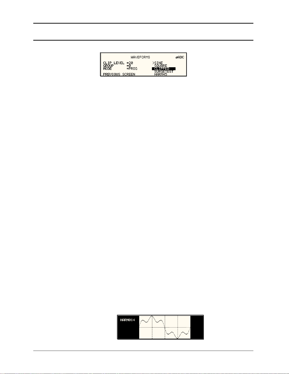
User Manual – Rev AJ California Instruments
4.2.7 WAVEFORMS Menu [3Pi Controller only]
Figu
re 4-17: WAVEFORMS Menu
The WAVEFORMS menu is ava ller only. If your unit has a P controller,
ilable on the 3Pi contro
pressing the WAVE key on the front panel function keypad has no effect. The WAVEFORMS
menu allows selection of the wa
three-phase mode, the mode is
ve shape for each phase individually or all phases at once. In
determined by the phase coupling.
The selected phase is shown in
wave shape will be applied to th
selected waveform will apply to
If single phase is selected on a 4
so pressing the PHASE button h ct.
the top right corner of the display (øA, øB or øC). The selected
at phase. If all phases are selected (phase coupling), the
all three phases.
5MX-3Pi model, the phase coupling is always set to phase A,
as no effe
The following fields are available in the WAVEFORMS menu:
CLIP LEVEL This parameter determines the amount of total harmonic
distortion of the built-in CLIPPED sine wave waveform. The
range is 0 % through 20 % THD.
Note that changing the distortion level of the CLIPPED sine
wave while the CLIPPED sine wave is used on the output of
one or more phases, forces the output of the AC Source to
be
dropped momentarily. To avoid this, make sure none of the
phases is using the CLIPPED sine wave function when
changing the clip level.
GROUP field displays the currently selected waveform group.
The group
There are four groups of 50 user-defined waveforms each for a
total of 200 waveforms
. Only one group can be active at a time
however. This field only displays the selected waveform group.
It cannot be used to change the actual group selected. Group
selection must occur at power up and is done from the INITIAL
SETUP 3 screen. See section 4.2.11.3 for details.
MODE
The mode field determines the operation mode of the
WAVEFORMS display screen. Available options for this field
are:
PROG: This mode is used to change the programmed
wave shape function on the selected phase. This is also the
default mode of operation.
VIEW (T): This mode can be used to display any of the
available user defined waveforms in a time domain display.
Previewing a waveform can
be useful if you are unsure about
the nature of the waveform that was stored.
100 MX Series
 Loading...