


Copyright 1995, 1996
by California Instruments.
All rights reserved.
P/N 4009-969
L Series and FCS-18 AC Power Source
Graphical User Interface
Software User Man ual
Revision C

L-Series and FCS-18- Graphical User Interface User Manual
(This page intentionally left blank)
2 California Instruments Rev C - June 1996

L-Series and FCS-18 Graphical User Interface User Manual
LIMITED WARRANTY
California Instruments believes the information contained in this manual is accurate. This document has been
carefully reviewed for technical accuracy. In the event that technical or typographical errors exist, California
Instruments reserves the right to make changes to subsequent editions of this document without prior notice
to holders of this edition. The reader should consult California Instruments if errors are suspected. In no event
shall California Instruments be liable for any damages arising out of or related to this document or the
information contained in it.
CALIFORNIA INSTRUMENTS PROVIDES NO WARRANTIES, EXPRESS OR IMPLIED, AND
SPECIFICALLY DISCLAIMS ANY WARRANTY OF MERCHANTABILITY OR FITNESS FOR A
PARTICULAR PURPOSE OF THIS SOFTWARE AND DOCUMENTATION. CALIFORNIA INSTRUMENTS
WILL NOT BE LIABLE FOR DAMAGES RESULTING FROM LOSS OF DATA, PROFITS, USE OF
PRODUCTS, OR INCIDENTAL OR CONSEQUENTIAL DAMAGES, EVEN IF ADVISED OF THE
POSSIBILITY THEREOF.
This limitation of liability of California Instruments will apply regardless of the form of action, whether in
contract or tort, including negligence. The warranty provided herein does not cover damages, defects,
malfunctions, or service failures caused by owner’s failure to follow California Instruments’ installation,
operation, or maintenance instructions; owner’s modification of the product; owner’s abuse, misuse, or
negligent acts; and power failures, surges, fire, flood, accident, actions of third parties, or other events outside
reasonable control.
SOME STATES DO NOT ALLOW LIMITATIONS ON THE LENGTH OF AN IMPLIED WARRANTY OR THE
EXCLUSION OR LIMITATION OF INCIDENTAL OR CONSEQUENTIAL DAMAGES, SO THE ABOVE
LIMITATION OR EXCLUSIONS MAY NOT APPLY TO YOU. THIS WARRANTY GIVES YOU SPECIFIC
LEGAL RIGHTS, AND YOU MAY ALSO HAVE OTHER RIGHTS WHICH VARY FROM STATE TO STATE.
If any part of this Agreement shall be determined by a court to be invalid, illegal or unenforceable, the
remaining provisions shall in no way be affected or impaired thereby.
GOVERNING LAW. This Agreement and Limited Warranty are governed by the laws of the state of California
without regard to conflict of law provisions.
INSTALLATION AND / OR USE OF THIS PROGRAM CONSTITUTES ACCEPTANCE OF THESE TERMS
AND RESTRICTIONS BY THE USER.
© 1995 COPYRIGHT
Under the copyright laws, this publication may not be reproduced or transmitted in any form, electronic or
mechanical, including photocopying, recording, storing in an information retrieval system, or translating, in
whole or in part, without the prior written consent of California Instruments Corporation.
California Instruments Corporation, ©1995
Warning regarding Medical and Clinical use of California
Instruments products.
California Instruments products are not designed with components and testing intended to ensure a level of
reliability suitable for use in the treatment and diagnosis of human beings. California Instruments products are
NOT intended to be used to monitor or safeguard human health and safety in medical or clinical treatment
and California assumes no responsibility for this type of use of its products or software.
Rev C - June 1996 California Instruments 3

L-Series and FCS-18- Graphical User Interface User Manual
(This page intentionally left blank)
4 California Instruments Rev C - June 1996

L-Series and FCS-18 Graphical User Interface User Manual
Table of Contents
1. Introduction.....................................................................................................................................................9
1.1 About this program...................................................................................................................................9
1.2 About this manual.....................................................................................................................................9
1.3 Software version.....................................................................................................................................10
2. Requirements ...............................................................................................................................................11
3. Setup and Installation...................................................................................................................................12
3.1 Connecting an L-Series AC source to PC..............................................................................................12
3.2 Installing the LSGUI software.................................................................................................................12
3.3 Installed files...........................................................................................................................................13
3.4 Manual installation..................................................................................................................................14
3.5 Software registration ..............................................................................................................................15
4. User Interface aspects..................................................................................................................................19
4.1 Starting the LSGUI.................................................................................................................................19
4.2 First : Save Configuration Data..............................................................................................................19
4.3 Main program window............................................................................................................................20
4.4 Menu Structure.......................................................................................................................................21
4.4.1 File menu ........................................................................................................................................22
4.4.2 Configuration menu.........................................................................................................................23
4.4.3 Source menu...................................................................................................................................24
4.4.4 Measurement menu........................................................................................................................25
4.4.5 Options menu..................................................................................................................................26
4.4.6 Applications menu...........................................................................................................................27
4.4.7 Help menu.......................................................................................................................................28
4.5 Selecting menu items with the mouse....................................................................................................29
4.6 Selecting menu items using the keyboard .............................................................................................29
4.7 Using the Toolbar...................................................................................................................................30
4.8 Status bar...............................................................................................................................................32
4.9 Modal and Non-Modal windows.............................................................................................................32
5. L-Series Hardware Configuration .................................................................................................................33
5.1 Model Number and Controller type selection screen .............................................................................34
5.2 System Settings screen..........................................................................................................................35
5.3 IEEE Interface screen ............................................................................................................................36
6. Source control...............................................................................................................................................37
6.1 Source Initialization ................................................................................................................................38
6.2 Steady State control...............................................................................................................................39
6.3 Steady state execution modes...............................................................................................................40
6.3.1 Update mode ..................................................................................................................................40
6.3.2 Immediate mode.............................................................................................................................40
6.4 Frequency control...................................................................................................................................41
6.4.1 Voltage derating for low frequencies...............................................................................................41
6.5 Voltage Range selection ........................................................................................................................42
6.5.1 Current limit adjustment..................................................................................................................42
6.6 Phase mode control ...............................................................................................................................43
6.6.1 Current limit adjustment..................................................................................................................43
6.7 Output relay control................................................................................................................................44
6.8 Current limit delay ..................................................................................................................................44
6.9 Phase controls........................................................................................................................................45
6.9.1 Voltage control................................................................................................................................45
6.9.2 Current limit control.........................................................................................................................45
6.9.3 Phase angle control ........................................................................................................................46
6.9.4 Waveform type selection ................................................................................................................46
7. Transients.....................................................................................................................................................47
7.1 Transient data entry ...............................................................................................................................48
Rev C - June 1996 California Instruments 5

L-Series and FCS-18- Graphical User Interface User Manual
7.1.1 Transient data Entry fields ..............................................................................................................48
7.1.2 Error checking.................................................................................................................................50
7.2 Transient types.......................................................................................................................................51
7.2.1 Voltage dropout transient................................................................................................................52
7.2.2 Voltage step transient .....................................................................................................................53
7.2.3 Voltage surge or sag transient ........................................................................................................54
7.2.4 Voltage sweep transient..................................................................................................................55
7.2.5 Frequency sweep transient.............................................................................................................56
7.2.6 Frequency surge or sag transient ...................................................................................................57
7.2.7 Frequency sweep transient.............................................................................................................58
7.2.8 Voltage and Frequency sweep transient.........................................................................................59
7.3 Linking transient registers together ........................................................................................................60
7.4 Transient phase selection.......................................................................................................................61
7.5 Downloading transient registers .............................................................................................................62
7.6 Managing multiple transient programs...................................................................................................63
7.6.1 Saving transient lists .......................................................................................................................63
7.6.2 Retrieving transient list....................................................................................................................63
7.6.3 Erasing transient lists......................................................................................................................64
7.6.4 Transient list file extension..............................................................................................................65
7.6.5 Automatic save on OK ....................................................................................................................65
7.7 Transient execution................................................................................................................................66
8. Measurements..............................................................................................................................................67
8.1 Selecting measurements........................................................................................................................68
8.2 Measurement modes..............................................................................................................................69
8.3 Stay on top feature.................................................................................................................................70
8.4 Data logging ...........................................................................................................................................71
8.4.1 Selecting a data file.........................................................................................................................71
8.4.2 Selecting the File Mode...................................................................................................................72
8.4.3 Selecting the time stamp format .....................................................................................................72
8.4.4 Data file comments .........................................................................................................................73
8.4.5 Data File Format .............................................................................................................................73
8.5 Using a spreadsheet program................................................................................................................75
8.6 Dynamic data exchange.........................................................................................................................76
9. Applications...................................................................................................................................................77
9.1 MIL-STD-704..........................................................................................................................................77
9.2 RTCA/DO-160........................................................................................................................................78
10. Calibration...................................................................................................................................................79
10.1 Calibration support features .................................................................................................................79
10.2 Unlocking calibration screens...............................................................................................................79
10.3 Output Calibration.................................................................................................................................80
10.3.1 P controller....................................................................................................................................80
10.3.2 PT controller..................................................................................................................................81
10.4 Measurement Calibration .....................................................................................................................83
11. Managing L-Series hardware configuration data........................................................................................85
11.1 Saving configuration data.....................................................................................................................85
11.2 Restoring configuration data.................................................................................................................86
11.3 Obtaining lost configuration data..........................................................................................................87
12. File Formats................................................................................................................................................89
12.1 Setup files (.stp)....................................................................................................................................90
12.2 Transient program files (.tls).................................................................................................................92
12.3 Data files. (.csv)....................................................................................................................................93
12.4 Measurement Calibration data files (.mcd)...........................................................................................94
13. Troubleshooting..........................................................................................................................................95
13.1 Card Not Found Problems....................................................................................................................96
13.1.1 GPIB.DLL replacement .................................................................................................................96
13.1.2 Non CIC Message.........................................................................................................................96
6 California Instruments Rev C - June 1996

L-Series and FCS-18 Graphical User Interface User Manual
13.1.3 Decimal separator.........................................................................................................................96
13.1.4 To resolve problems 2 and 3, follow these steps:.........................................................................96
13.2 Interface problems .............................................................................................................................102
13.2.1 Wrong IEEE address..................................................................................................................102
13.2.2 Incompatible IEEE card ..............................................................................................................103
13.2.3 Card not at specified I/O address ...............................................................................................104
13.3 Constant or Frequent Syntax Error messages...................................................................................104
13.4 Configuration errors............................................................................................................................104
13.5 Parameter conflicts ............................................................................................................................105
13.6 Problems not listed.............................................................................................................................105
13.7 Problem report forms .........................................................................................................................106
14. Index.........................................................................................................................................................109
Rev C - June 1996 California Instruments 7

L-Series and FCS-18- Graphical User Interface User Manual
(This page intentionally left blank)
8 California Instruments Rev C - June 1996

1. Introduction
1.1 About this program
The L Series Graphical User Interface program - LSGUI - was developed
as a companion product to the California Instrument line of AC power
sources. It’s main purpose is to provide a soft front panel to the instrument
when connected to a PC through the IEEE-488 bus interface. Additional
benefits are obtained from using the PC as a control interface. Some of
these benefits include the ability to store measurement data to disk and
interact with other programs.
The LSGUI is a Windows 3.1™ program and as such requires a PC
capable of running Windows 3.1™, Windows 3.11™, Windows for
Workgroups 3.11™ or Windows 95™.
This user manual provides a complete overview of the program’s
operation. It also lists details on file formats and other details that may be
needed in order to use this program successfully. Extensive information can
also be found in the on-line help supplied with the program. Use the Help
menu or press on any of the many Help keys located in all program windows
for an explanation of the relevant screen or function.
L-Series and FCS-18 Graphical User Interface User Manual
As always, California Instruments appreciates your patronage and would
welcome any comments and suggestions you might have regarding this
software or any of its other products. Use the customer feedback form
located in the back of this manual. The same form can be used to report
software bugs should you encounter any.
1.2 About this manual
Note that this manual covers the operation of the LSGUI software only. It
is strongly recommended that you familiarize yourself with the operation of
the L-Series power source as well. This is best done by studying the
instruction manual supplied with the AC source.
Rev C - June 1996 California Instruments 9

L-Series and FCS-18- Graphical User Interface User Manual
1.3 Software version
From time to time, it may be necessary to release a new version of the
LSGUI software to fix bugs and or add new features and capabilities. This
will result in the decimal portion of the version number being increased. In
this case, it is unlikely that a new user manual would be required.
Addendum’s and changes to this manual will be provided in the form of a
readme.txt file on the distribution disk. As such, you will not normally receive
an new manual when you receive a new software version. Major changes to
the functionality or operation of this software may require a new manual
version as well. In this case, the integer version number part will be
increased and a new manual version will be issued.
If the LSGUI software version you are using is 1.X with X from 0 to 9,
continue to use this manual. If the version number is 2.X or higher, contact
California Instruments to obtain an updated manual. Production and shipping
charges will apply.
10 California Instruments Rev C - June 1996
2. Requirements
To successfully install and operate the LSGUI program, you will need the
following equipment :
L-Series AC power source. Supported models are : 751L 6000L
1501L 9000L
1503L 12000L
2000L 13500L
2750L 18000L
4500L
-P or -PT programmable controller. Manual controller (Type -M) equipped
•
L-Series AC sources can not be operated by this program. Contact
California Instruments for information on upgrading to a -P or -PT
controller.
PC capable of running Windows 3.1™, Windows for Workgroups 3.11™
•
or Windows 95™
National Instruments PC/IIA or PC-AT/TNT IEEE interface card. Other
•
vendor IEEE interface cards are not supported unless they are
compatible at the DLL level2.
IEEE Cable
•
L-Series and FCS-18 Graphical User Interface User Manual
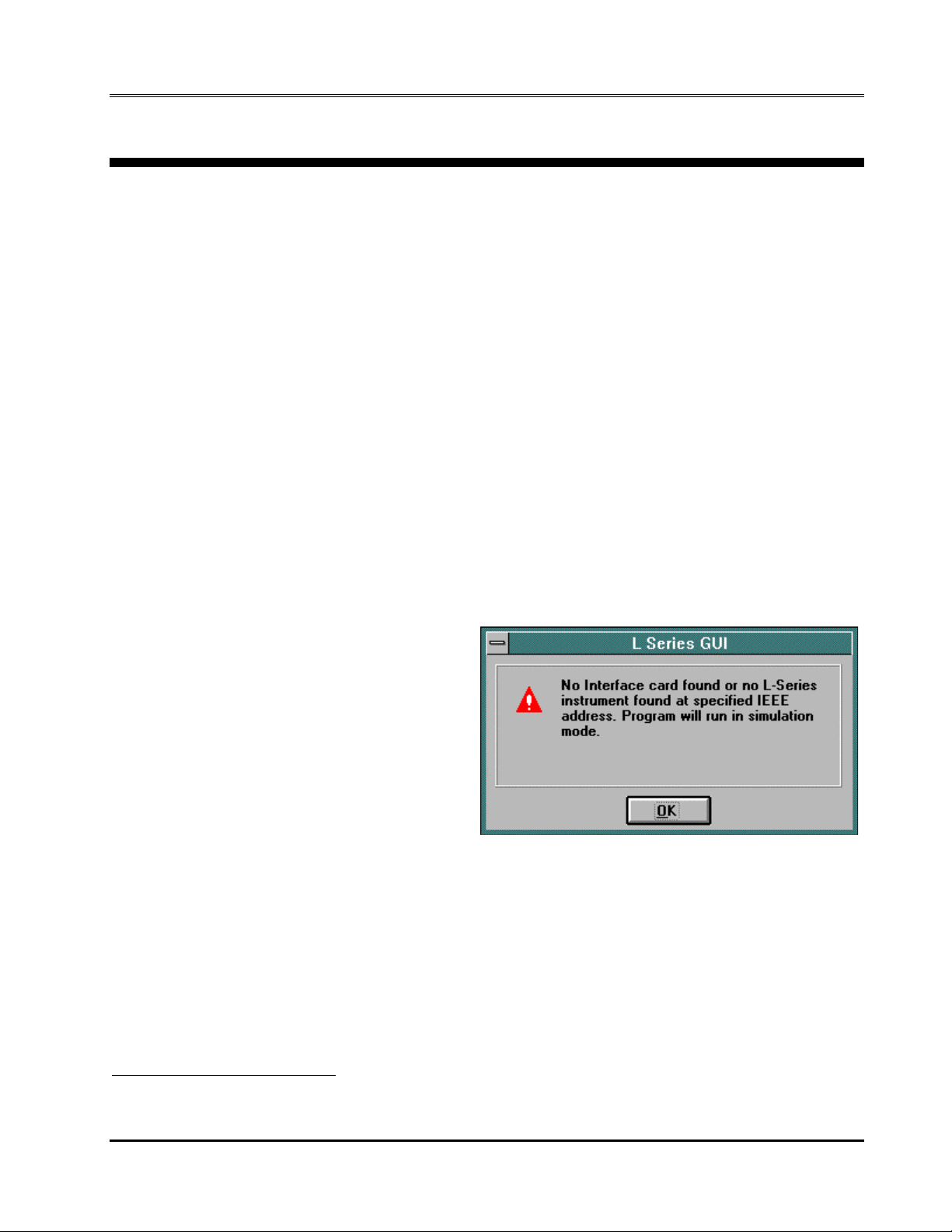
1
Note that the LSGUI can
be run in the absence of an
L-Series power source. If no
AC source is available or a
suitable IEEE controller card
cannot be found, the LSGUI
can be operated in a
simulation mode. The
program will detect these
conditions and start up in
simulation mode after
notifying the operator. Measurements in this case will be simulated and
should not be used for any analytical purpose.
1
This model is not available at this time and is supported for future compatibility only.
2
DLL compatibility implies identical functional calls and parameters as the National Instruments GPIB.DLL.
Rev C - June 1996 California Instruments 11

L-Series and FCS-18- Graphical User Interface User Manual
3. Setup and Installation
This section covers installation of the LSGUI from the distribution disk to
the user’s PC. Make sure the PC is capable of running Windows 3.1™
Enhanced mode or equivalent with at least 4 Mbyte of memory and 2 Mbyte
of available hard disk space.
3.1 Connecting an L-Series AC source to PC
Connect the L-Series AC source to the PC using a suitable IEEE
interface cable. Make sure you screw down the IEEE connectors securely or
they will not make good contact. The IEEE address used by the L-Series
power source is retained in non volatile memory. Factory setting is normally
1 but this address may have been changed from the front panel.
3.2 Installing the LSGUI software
The LSGUI software is distributed on a 3.5 inch high density diskette.
The GUI must be installed from this diskette as all required files are
compressed. You cannot copy the contents of this disk to your PC hard drive
and run it. To install the LSGUI, proceed as follows :
1. Turn on the PC and boot up in Windows 3.1™.
2. Insert the LSGUI disk in drive A or B. If you do not have a 3.5 inch drive
on the PC, you can copy the contents of the disk to a 5.25 inch diskette
on a PC that is equipped with both drive types.
3. From the Program Manager, select the “File” Menu.
4. From the File Menu, select “Run...”
5. At the prompt, type “A:SETUP” or “B:SETUP” depending on the drive
designator of the drive in which you inserted the disk.
The setup program will first ask you for the destination directo ry on th e hard
disk where you want the LSGUI installed. The default directory is “C:\LSGUI”
6. Press “Continue” if you want to accept the default. If you want the
program to reside at a different location, type in the complete path name
including hard disk drive letter and then press “Continue”. If you want to
abort the setup procedure, click on the “Exit Setup” button. A warning will
appear indicating the setup did not complete successfully. Click on the
“OK” button to acknowledge the warning. This will take you back to the
Program Manager.
7. Wait for the installation program to complete. An icon for the LSGUI, the
LSGUI help file and a program group will be created automatically.
8. Remove the diskette from the drive.
You are now ready to start using the LSGUI software.
If you experience problems during the installation process, refer to
chapter 13 on troubleshooting.
12 California Instruments Rev C - June 1996

3.3 Installed files
The installation program will install the following files in the directories
specified. Note that files with the same name that already exists in these
directories will be overwritten as part of the installation process. As long as
the files being overwritten are of an older date (previous version), this should
not cause any problems. If however you have newer versions of some of
these files, we recommend you back these files up prior to running the
installation program and then restore them afterwards.
Application directory files:
The following files are copied to the application directory. The application
directory name is chosen by the user at the time of installation. In this
manual, the default application directory name LSGUI is used.
path and filename size in bytes date
.\lsgui\lsgui.exe 216438 9/15/95
.\lsgui\lsgui.hlp 62601 9/13/95
.
Windows system directory files:
The following support files are copied to the windows system directory:
path and filename size in bytes date
.\windows\system\fpgrid10.vbx 409200 5/12/95
.\windows\system\cmdialog.vbx 18688 4/28/93
.\windows\system\spin.vbx 22528 10/21/92
.\windows\system\threed.vbx 64432 7/17/93
.\windows\system\mhtip.vbx 35040 7/21/95
.\windows\system\mhrun400.ddl 94352 7/21/95
.\windows\system\commdlg.ddl 89248 3/10/92
.\windows\system\gpib.ddl 90624 8/31/94
.\windows\system\ver.ddl 9696 10/5/94
.\windows\system\setupkit.ddl 7008 4/28/93
.\windows\system\vbrun300.ddl 398416 6/3093
L-Series and FCS-18 Graphical User Interface User Manual
Rev C - June 1996 California Instruments 13

L-Series and FCS-18- Graphical User Interface User Manual
3.4 Manual installation
If the installation program is unable to complete the installation process
successfully, you may attempt to manually install the files listed in section
3.3. All files on the distribution diskette are compressed so they cannot be
copied directly to the hard disk. Instead, use the “
is located in the DOS directory of your PC. The correct syntax to use is :
expand -r a:\source destination
The directory path for the destination files should be specified as part of the
destination.
expand.exe
” program that
14 California Instruments Rev C - June 1996

3.5 Software registration
We encourage you to send in the software end-user registration form
located on the next page. Only registered users will be informed of software
updates and bug fixes that may be released from time to time. Please mail
the completed end-user registration form to the following address:
California Instruments Corporation
Attn: Customer Satisfaction Department
9689 Towne Centre Drive
San Diego, CA 92121
U.S.A.
You can also fax a copy of the form to the fax number listed below:
(858) 677-0940
L-Series and FCS-18 Graphical User Interface User Manual
(Please specify “Customer Satisfaction Department” on your fax cover page.)
Rev C - June 1996 California Instruments 15

L-Series and FCS-18- Graphical User Interface User Manual
(This page intentionally left blank)
16 California Instruments Rev C - June 1996
L-Series and FCS-18 Graphical User Interface User Manual
California Instruments Corporation
Software End-user Registration Form
Complete and submit to:
California Instruments Corporation
Attn: Customer Satisfaction Department
9689 Towne Centre Drive
San Diego, CA 92121
United States of America
End-user information
Company _________________________ Division __________________________
Contact _________________________ Title __________________________
Department _________________________
Address _________________________ Mailstop __________
City _________________________ State ______ Zip _______
Phone ____-____________________ Fax ____-_____________________
Software revision:
Program L-Series Graphical user interface Version _________
Rel Date ___ / ___ / 19___
Company use only:
Date received : Receipt acknowledgment sent : yes / no
Updated version sent : ___ / ___ / 19___ Processed by : _____________
CI-SWRF Sept-1995
Rev C - June 1996 California Instruments 17

L-Series and FCS-18- Graphical User Interface User Manual
(This page intentionally left blank)
18 California Instruments Rev C - June 1996
L-Series and FCS-18 Graphical User Interface User Manual
4. User Interface aspects
This chapter reviews the various user interface aspects of the LSGUI
program. It covers menus and mouse operation. Experienced Windows
users can skip sections 4.4 and 4.6.
4.1 Starting the LSGUI
Use the mouse to double click on the LSGUI icon (). If you are not
comfortable double clicking with a mouse, you can also click on the icon
once to select it, and then press the Enter key. The program will
load and display the main program window screen.
4.2 First : Save Configuration Data
Before continuing on with this program, be sure to save your L-Series
hardware configuration. See chapter 11 for details on how to do this.
Rev C - June 1996 California Instruments 19
L-Series and FCS-18- Graphical User Interface User Manual
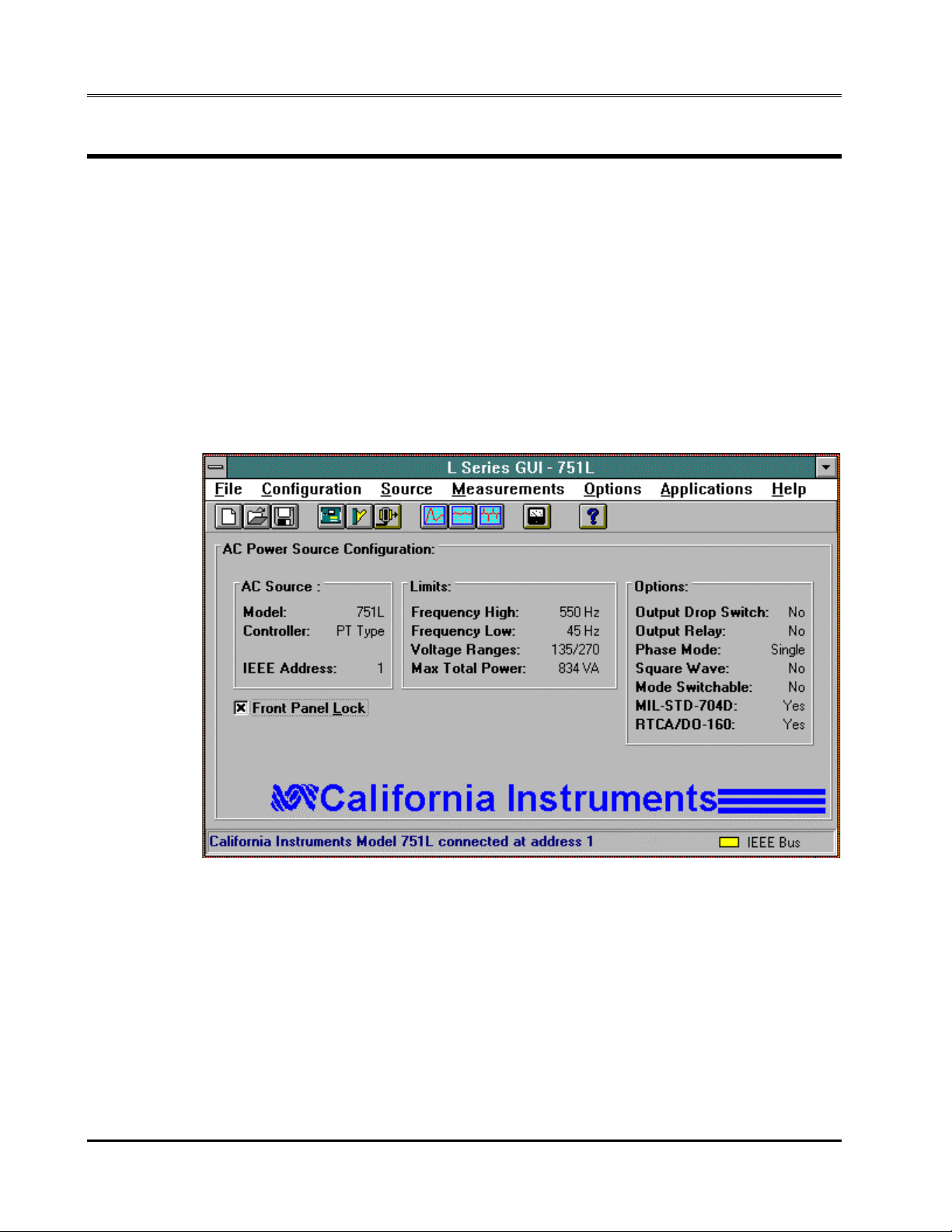
4.3 Main program window
The LSGUI software is operated through a series of modal dialog boxes
or screens that are all accessed from the main menu bar. The main menu
bar is shown along the top edge of the main program window. Located
directly below the main menu bar is the toolbar or buttonbar. The toolbar
provides mouse click shortcuts for the most commonly accessed menus and
sub-menus. The toolbar can be made invisible from the options menu if
screen real estate is small or the user does not like using the mouse.
Below the menu and toolbar is the main program screen area. Here,
information on the L-Series power source that was detected on the IEEE-488
bus is displayed.
Figure 1 Main Program Window
20 California Instruments Rev C - June 1996

4.4 Menu Structure
The main menu provides access to all windows and screens available in
the LSGUI program. It is organized in logical groups that cover different
aspects of AC source control. The purpose of each menu group is discussed
briefly in this chapter. More detailed information can be found in the relevant
chapters that follow. Figure 2 provides a flowchart of all available menus and
sub-menus in the LSGUI program.
L-Series and FCS-18 Graphical User Interface User Manual
Main menu
Sub-menu
File
Configuration
Source
Measurements
Options
Applications
Help
New
Open...
Save
Save As..
Exit
Model...
System Settings...
IEEE Interface...
Initialization...
Steady State...
Transients...
Show...
Data File...
Show Toolb ar
Save Configur ati o n File...
Restore Config uration File.. .
MIL-STD-704
RTCA/DO-160
Contents...
Search for Help on...
Index...
How to use Help
About...
Figure 2 LSGUI program Menu structure
Rev C - June 1996 California Instruments 21

L-Series and FCS-18- Graphical User Interface User Manual
4.4.1 File menu
The File menu allows access to instrument setup files that are stored in
setup files. It also provides the means to close and exit the program. The
following File Menu entries exist :
Submenu Purpose
New Resets all setup information to default values. If an actual
L-Series is connected to the PC, hardware configuration
data remains unchanged.
Open... Opens the
File Open
dialog box. User can select setup file
to load
Save Save present settings to disk setup file. If no setup was
loaded previously, the
File Save As...
appear prompting the user for a name to save the setup
under. If a setup file was opened previously, the new
settings will be used to overwrite the same setup file. To
avoid this, use the
File Save As...
Save As... Save present settings to disk setup file. A ‘
dialog box will appear prompting the user for a name to
save the setup under.
Exit Closes the LSGUI program. The IEEE-488 interface is
released and all program elements are unloaded from the
PC’s memory. The same can be accomplished by pressing
ALT-F4 on the keyboard.
dialog box will
menu instead.
File Save As...
’
22 California Instruments Rev C - June 1996

4.4.2 Configuration menu
The configuration menu allows the user to change the configuration of
the LSGUI program and the IEEE-488 interface. It also provides access to
the L-Series hardware configuration screen. Note that the L-Series hardware
configuration cannot be changed by the end-user. It is set at the factory at
the time of shipment. You can however save the configuration data to disk in
case the non-volatile memory contents ever gets lost. Refer to section 11.
The L-Series hardware configuration screen also provides access to the
Calibration screens. To unlock the calibration screens, a calibration
password is required. This password is normally known to authorized
personnel only. This security measure is added to facilitate compliance with
quality standards that call for traceable calibration data and audit trails.
Without the correct password, the LSGUI program cannot be used to change
calibration data.
The calibration password for version 1.0 of the LSGUI software is printed
on the original distribution disk. Make sure you keep this information in a
secure place and provide the password only to qualified personnel.
L-Series and FCS-18 Graphical User Interface User Manual
The following three sub-menus are available from the Configuration
menu:
Submenu Purpose
Model... Opens the model selection dialog box. This dialog box
allows different L series models to be selected for
simulation purposes. The L-Series Model can only be
changed when in simulation mode. Changing models will
affect the look of certain other screens and controls.
System Settings... Opens the L-Series configuration and limits dialog
screen. This screen displays installed options and
hardware configuration parameters. It also provides
access to output and measurement calibration screens
IEEE Interface... Opens the IEEE interface settings screen. This screen
allows the user to select a different IEEE address from 1
through 30. L-Series AC sources are factory set to IEEE
address 1. Note that the IEEE address set in the LSeries non volatile setup memory cannot be changed
from the LSGUI. It needs to be set or changed from the
front panel. Refer to the L-Series instruction manual for
details. The IEEE address used by the LSGUI software
however can be changed to match the one set on the LSeries. Refer to section 5.3 for details.
Rev C - June 1996 California Instruments 23

L-Series and FCS-18- Graphical User Interface User Manual
4.4.3 Source menu
The source menu provides front panel control of the L-Series. Available
sub-menus are :
Submenu Purpose
Initialization... Opens the Source Initialization window. Initialization
parameters for frequency, voltage (all phases in a three
phase system), current limit and voltage range can be
set from the Initialization window. Changes made to this
window will be sent to the L-Series when the OK button
is clicked.
Steady State... Opens the Steady State window. This is the virtual front
panel or soft front panel of the L-Series. This window is
non-modal and can be left open at all times while the
LSGUI program is running.
Transients... Opens the Transients windows. This modal window is
used to program the sixteen transient registers available
in the L-Series -P and -PT controllers. The same window
also provides a means to start transient execution from
any register.
24 California Instruments Rev C - June 1996

4.4.4 Measurement menu
The measurement menu provides only two sub-menus. They are :
Sub-menu Purpose
Show... Opens the measurement window. This is a non-modal
Data File... Opens a dialog box that allows the user to select a data
L-Series and FCS-18 Graphical User Interface User Manual
window which can be left open at all times. The
measurement window provides constant readouts of up
to 19 parameters. Different screen colors are used to
indicate different phases.
file for recording of measurement data. If no file is
selected from this sub-menu and data logging is
enabled, data will be written to the default data file called
LS_GUI.CSV. The default file mode is “overwrite” so old
data will be lost if no specific data logging file name is
selected.
Rev C - June 1996 California Instruments 25

L-Series and FCS-18- Graphical User Interface User Manual
4.4.5 Options menu
The options menu provides functions that logically cannot be grouped
under any other main menu heading. Specifically, the following three submenus are available:
Submenu Purpose
Show Toolbar This menu entry provides a toggle function to
enable or disable the toolbar at the top of the
main program window. The status of the
toolbar (visible or not) is indicated by a check
mark next to the ‘Show Toolbar’ sub-menu
entry. A check mark indicates the Toolbar is
visible. No check mark indicates the toolbar is
not visible.
Save Configuration File... Opens a dialog box which allows the user to
save the present hardware configuration data
for the connected L-Series unit to a disk file.
The serial number of the unit needs to be
specified and will be used as the file name.
Saving configuration data may be important in
case a loss of non-volatile memory is ever
experienced. Using this option, the user is
able to create a library of configuration files for
all L-Series AC power sources owned.
Restore Configuration File... Opens a dialog box which lists all available L-
Series configuration files found in the LSGUI
working directory. Selecting any of the listed
files will allow its contents to be downloaded to
the connected L-Series unit.
26 California Instruments Rev C - June 1996

4.4.6 Applications menu
The Applications menu may or may not appear when running the LSGUI
program. Its presence is determined by the availability of the MIL-STD-704
and RTCA/DO-160 application options in the connected L-Series AC source.
If neither option is detected, the Applications menu will not be shown at all. If
at least one of the two possible application is available, the Application menu
does become visible and one or two sub-menus will be shown. They are :
Submenu Purpose
MIL-STD-704... When available, this sub-menu opens a dialog box
RTCA/DO-160 When available, this sub-menu opens a dialog box
L-Series and FCS-18 Graphical User Interface User Manual
which enables the user to select all or a subset of MILSTD-704 test programs. Program execution can be
started from this sub-menu as well.
which enables the user to select all or a subset of
RTCA/DO-160 test programs. Program execution can be
started from this sub-menu as well.
Note : If the L-Series unit connected to the PC does not have either
option, this menu will not be available. If the reader is interested in one or
both of these options, switch to the simulation mode. In simulation mode, all
options can be simulated. This allows the reader to review the available
capabilities. L-Series units can be retrofitted with both application options.
Contact California Instruments or their local representative for details.
Rev C - June 1996 California Instruments 27

L-Series and FCS-18- Graphical User Interface User Manual
4.4.7 Help menu
The Help menu is a standard menu found in all Windows applications. It
provides access to on-line context sensitive help information. The following
sub-menus are available :
Contents... Opens the LSGUI help file at the contents page. From
the contents page, a selection of topics is available.
Search for Help on Opens the LSGUI help file in the Search dialog mode.
Use this sub-menu to look for help on a specific topic.
Index Opens the LSGUI help file at the index page. The index
page lists all key words and provides jumps to the
relevant help topic that covers the concept.
How to use Help Opens the generic windows Help file on the How to Use
Help page. If the user is not familiar with the Windows
help engine, this topic may be appropriate.
About... Opens the About LSGUI dialog box. This dialog box
displays information on the programs release version
and date. It also shows a summary of the PC’s available
resources. This information may be relevant if you are
experiencing problems due to limited resources.
28 California Instruments Rev C - June 1996

L-Series and FCS-18 Graphical User Interface User Manual
4.5 Selecting menu items with the mouse
To select any menu item using the mouse, move the mouse pointer to
the desired entry and press the left mouse button. (Click)
4.6 Selecting menu items using the keyboard
To select any menu using the keyboard, hold down the ALT key and
press the letter of the menu item that is underlined. Thus, to select the “File”
menu item, hold down the ALT key and press the letter “F”.
Rev C - June 1996 California Instruments 29
L-Series and FCS-18- Graphical User Interface User Manual
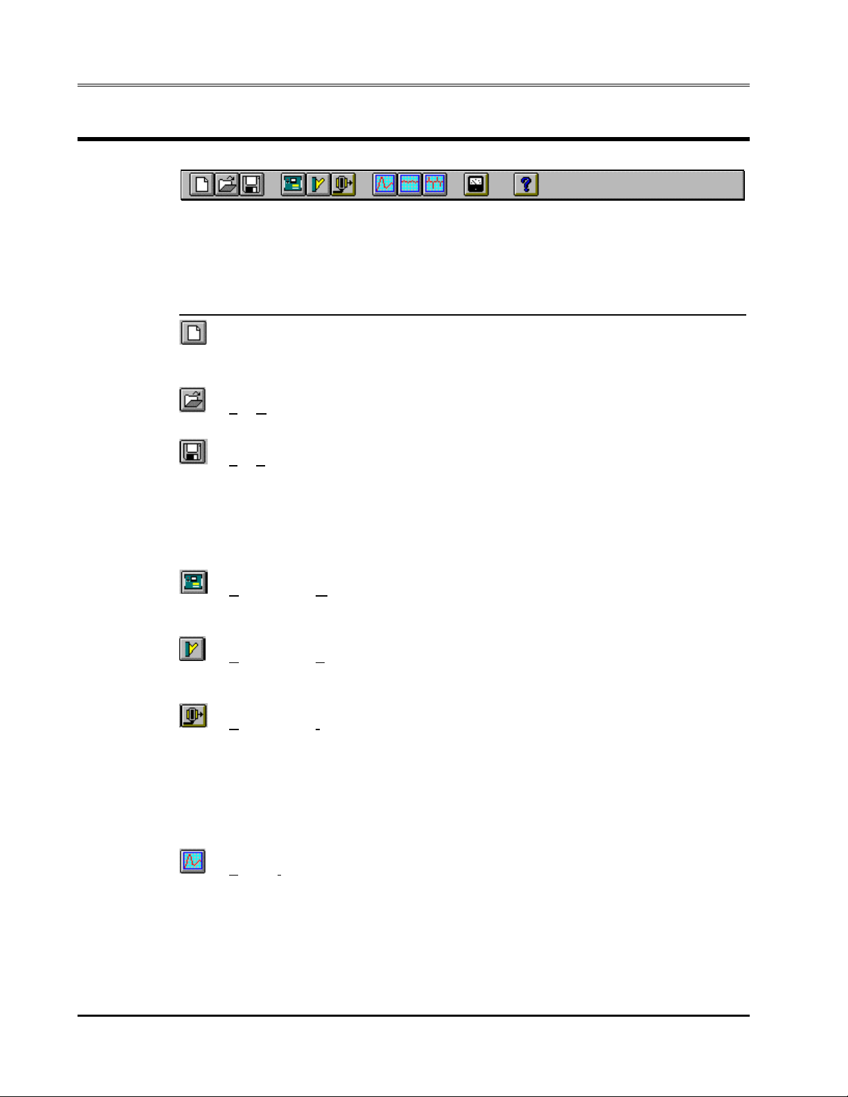
4.7 Using the Toolbar
The toolbar provides a c onvenient shortcut for mouse savvy operators.
Clicking on each of the toolbars icons will cause the corresponding menu
and sub-menu to be selected at once. The following toolbar icons and their
corresponding menu equivalents are provided :
Icon Menu equivalent Description
File-New Resets all setup information to default values. If
an actual L-Series is connected to the PC,
hardware configuration data remains unchanged.
File-Open... Opens the File Open dialog box. User can select
setup file to load.
File-Save Save present settings to disk setup file. If no
setup was loaded previously, the File Save As...
dialog box will appear prompting the user for a
name to save the setup under. If a setup file was
opened previously, the new settings will be used
to overwrite the same setup file. To avoid this,
use the File Save As... menu instead.
Configuration-Model Allows different L series models to be selected
for simulation purposes. Model can only be
changed when in simulation mode.
Configuration-System Settings... Shows installed options and hardware
configuration. Also provides access to output and
measurement calibration screens.
Configuration-IEEE Interface... Opens the IEEE interface setting and command
line screen. This screen can be used to change
the IEEE address used to communicate with the
L-Series AC source. An interactive command
line is provided as well to allow the user to send
IEEE commands directly to the instrument. All LSeries APE commands are available from a drop
down list.
Source-Initialization... Opens the initial settings window. This window is
used to inspect and change the initial power up
settings.
30 California Instruments Rev C - June 1996
 Loading...