

Page 1

By California Instruments.
Model 251TL / 351TL
AC Power Source
User and Programming Manual
Revision C
November 2001
Copyright 2001
All rights reserved.
P/N 7351-960
TEL: +1 (858) 677-9040
FAX: +1 (858) 677-0940
Email: [email protected]
Web Site: http://www.calinst.com
Page 2

User and Programming Manual - Rev C
User and Programming Manual
AC Power Source
California Instruments
Models:
• 251TL, 351TL
• Options: -L22, -OP1, -SKT, -RMS, -EXT
Copyright 2001 California Instruments, Rev C, November 2001
TL Series November 2001 i
Page 3
User and Programming Manual - Rev C
SAFETY SUMMARY
This power source contains high voltage and current circuits that are potentially lethal.
Because of its size and weight, electrical and mechanical stability must be ensured. The
following safety guidelines must be followed when operating or servicing this equipment.
These guidelines are not a substitute for vigilance and common sense. If this power
source is not used as specified in this manual, the protection provided by this equipment
may be impaired. California Instruments assumes no liability for the customer's failure to
comply with these requirements.
APPLYING POWER AND GROUNDING
Verify the correct voltage is applied to the unit (100 / 115 / 200 or 230 VAC Nominal). Verify that the
input power wiring is connected to a properly grounded utility outlet.
FUSES
Use only fuses of the specified current, voltage, and protection speed.
Do not short out the fuse holder or use a repaired fuse.
The main supplies in the 351TL use a North American ferrule fuse rated at
30A. (Fast Acting)
DO NOT OPERATE IN A VOLATILE ATMOSPHERE
Do not operate the power source in the presence of flammable gases or fumes. This product is
designed to operate in a controlled environment. Do not expose to rain or snow.
DO NOT TOUCH ENERGIZED CIRCUITS
Disconnect the power cable before servicing this equipment. Only qualified service personnel
may remove covers, replace components or make adjustments.
DO NOT SERVICE ALONE
Do not remove covers, replace components, or make adjustments unless another person, who
can administer first aid, is present.
DO NOT EXCEED INPUT RATINGS
Do not exceed the rated input voltage or frequency. Additional hazards may be introduced
because of component failure or improper operation.
DO NOT MODIFY INSTRUMENT OR SUBSTITUTE PARTS
Do not modify this instrument or substitute parts. Additional hazards may be introduced because
of component failure or improper operation.
MOVING THE POWER SOURCE
When moving the power source, observe the following:
1. Remove all AC power to unit.
2. Use two people to prevent injury.
SURFACE STABILITY
Operate the power source only on a level surface.
ii November 2001 TL Series
Page 4

User and Programming Manual - Rev C
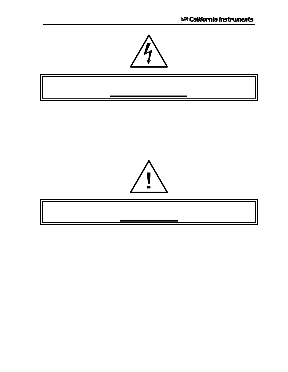
Electrical Safety Symbols Used in This Manual
TL Series November 2001 iii
Page 5

User and Programming Manual - Rev C
WARRANTY INFORMATION
CALIFORNIA INSTRUMENTS CORPORATION warrants each instrument manufactured by
them to be free from defects in material and workmanship for a period of one year from the
date of shipment to the original purchaser. Excepted from this warranty are fuses and
batteries that carry the warranty of their original manufacturer where applicable.
CALIFORNIA INSTRUMENTS will service, replace, or adjust any defective part or parts, free
of charge, when the instrument is returned freight prepaid, and when examination reveals
that the fault has not occurred because of misuse, abnormal conditions of operation, user
modification, or attempted user repair. Equipment repaired beyond the effective date of
warranty or when abnormal usage has occurred will be charged at applicable rates.
CALIFORNIA INSTRUMENTS will submit an estimate for such charges before commencing
repair, if so requested.
If a fault develops, notify CALIFORNIA INSTRUMENTS at [email protected] or its local
representative, giving full details of the difficulty, including the model number and serial
number. On receipt of this information, service information or a Return Material Authorization
(RMA) number will be given. Add the RMA number furnished to the shipping label. Pack the
instrument carefully to prevent transportation damage, affix label to shipping container, and
ship freight prepaid to the factory. CALIFORNIA INSTRUMENTS shall not be responsible for
repair of damage due to improper handling or packing. Instruments returned without RMA
No. or freight collect may be refused at California Instruments discretion. Instruments
repaired under Warranty will be returned either via prepaid surface freight or low cost
airfreight at California Instruments discretion. Instruments repaired outside the Warranty
period will be returned freight collect, Ex Works CALIFORNIA INSTRUMENTS 9689 Towne
Centre Drive, San Diego, CA 92121-1964. If requested, an estimate of repair charges will
be made before work begins on repairs not covered by the Warranty.
SERVICE PROCEDURE
DAMAGE IN TRANSIT
The instrument should be tested when it is received. If it fails to operate properly, or is
damaged in any way, a claim should be filed immediately with the carrier. The claim agent
should obtain a full report of the damage, and a copy of this report should be forwarded to us
by fax or email (Fax: 858 677 0940, Email: [email protected]). CALIFORNIA
INSTRUMENTS will prepare an estimate of repair cost and repair the instrument when
authorized by the claim agent. Please include model number and serial number when
referring to the instrument.
SPARE PARTS
To order spare parts, user manuals, or determine the correct replacement part for your
California Instruments products, please contact the Customer Service department by phone
at + 1 858 677 9040, press 2 or by email [email protected].
iv November 2001 TL Series
Page 6

User and Programming Manual - Rev C
Table of Contents
1 Introduction.....................................................................................................................................1
1.1 General Description...............................................................................................................................1
1.2 Accessory Equipment/Rack Slides........................................................................................................1
2 Specifications..................................................................................................................................3
2.1 Electrical................................................................................................................................................3
2.2 Measurements [Option].........................................................................................................................6
2.3 System Specification.............................................................................................................................7
2.4 Unit Protection.......................................................................................................................................8
2.5 Mechanical.............................................................................................................................................8
2.6 Environmental........................................................................................................................................9
2.7 Regulatory.............................................................................................................................................9
2.8 Front Panel Controls............................................................................................................................10
2.9 Available Options.................................................................................................................................10
3 Installation and Functional Test....................................................................................................11
3.1 Unpacking............................................................................................................................................11
3.2 Power Requirements...........................................................................................................................11
3.3 Input Voltage Range Selection............................................................................................................13
3.4 Mechanical Installation........................................................................................................................17
3.5 Input Wiring.........................................................................................................................................17
3.6 Output Connections.............................................................................................................................17
3.7 Output Voltage Ranges.......................................................................................................................18
3.8 Functional Test....................................................................................................................................19
3.9 Current Limit - Modes of Operation.....................................................................................................21
4 Front Panel Operation ..................................................................................................................23
4.1 Functional Controls..............................................................................................................................23
4.2 How to Examples.................................................................................................................................28
4.3 Setting the Power on Initialization Values............................................................................................31
4.4 Current Limit Modes............................................................................................................................32
4.5 Function Strobe [Option]......................................................................................................................33
4.6 Remote Inhibit [Option]........................................................................................................................33
5 Principle of Operation ...................................................................................................................35
5.1 General................................................................................................................................................35
5.2 Overall Description..............................................................................................................................35
5.3 Input Power Supply..............................................................................................................................35
5.4 Range Relay Board.............................................................................................................................39
5.5 Amplifier...............................................................................................................................................39
5.6 Controller Module................................................................................................................................39
5.7 IEEE 488/ RS232 Interface [Option]....................................................................................................40
6 Calibration.....................................................................................................................................43
6.1 Calibration Equipment.........................................................................................................................43
6.2 Selecting Calibration Mode..................................................................................................................44
6.3 Routine Calibration..............................................................................................................................45
6.4 Non-Routine Calibration......................................................................................................................49
7 Service..........................................................................................................................................53
7.1 General................................................................................................................................................53
7.2 Basic Operation...................................................................................................................................53
7.3 Module Removal..................................................................................................................................55
7.4 Replaceable Parts...............................................................................................................................58
TL Series November 2001 v
Page 7

User and Programming Manual - Rev C
8 Remote Control ............................................................................................................................59
8.1 Introduction.........................................................................................................................................59
8.2 PGUI32 Program Requirements.........................................................................................................59
8.3 IEEE Interface.....................................................................................................................................61
8.4 RS232C Interface................................................................................................................................62
8.5 PGUI32 Setup and Installation............................................................................................................ 64
8.6 Trouble Shooting - RS232C................................................................................................................66
8.7 Trouble Shooting - IEEE-488 / GPIB...................................................................................................69
8.8 PGUI32 Distribution Files.................................................................................................................... 70
8.9 Software Registration.......................................................................................................................... 71
9 Introduction to SCPI .....................................................................................................................73
9.1 Conventions Used in This Manual.......................................................................................................73
9.2 The SCPI Commands and Messages.................................................................................................73
9.3 Using Queries .....................................................................................................................................76
9.4 Structure of a SCPI Message..............................................................................................................76
9.5 SCPI Data Formats.............................................................................................................................79
10 SCPI Command Reference......................................................................................................81
10.1 Subsystem Commands....................................................................................................................... 81
10.2 Calibration Subsystem ........................................................................................................................82
10.3 Measurement Subsystem....................................................................................................................87
10.4 Source Subsystem.............................................................................................................................. 90
10.5 Output Subsystem............................................................................................................................... 94
10.6 Limit Subsystem..................................................................................................................................97
10.7 Display Subsystem.............................................................................................................................. 99
10.8 System Commands...........................................................................................................................100
10.9 Common Commands ........................................................................................................................102
11 Programming Examples .........................................................................................................110
11.1 Introduction ....................................................................................................................................... 110
11.2 Programming the Output...................................................................................................................110
11.3 Making Measurements......................................................................................................................112
12 Status Registers......................................................................................................................114
12.1 Power-On Conditions........................................................................................................................114
12.2 Standard Event Status Group ........................................................................................................... 115
12.3 Status Byte Register..........................................................................................................................115
12.4 Examples...........................................................................................................................................116
Appendix A : SCPI Command tree....................................................................................................117
Appendix B : SCPI Conformance Information...................................................................................118
Appendix C : Error Messages............................................................................................................119
Index..................................................................................................................................................120
vi November 2001 TL Series
Page 8

User and Programming Manual - Rev C
List of Figures
Figure 2-1: Output Power Rating as a Function of Voltage and Load PF.............................................5
Figure 3-1: Model 251TL / 351TL AC Power Source..........................................................................11
Figure 3-2: Rear Panel View...............................................................................................................12
Figure 3-3: Connections to T1 for 105 - 125V Line Input....................................................................14
Figure 3-4: Connections to T1 for 210 - 250V Line Input....................................................................16
Figure 3-5: Test Setup 351TL.............................................................................................................20
Figure 4-1: Front Panel View ..............................................................................................................23
Figure 4-2: Voltage Auto Range Switch Over Points..........................................................................25
Figure 4-3: Shuttle Knob.....................................................................................................................26
Figure 5-1: AC Power System Block Diagram....................................................................................37
Figure 6-1: Test Equipment Hookup for Routine Output and Voltage Measurement Calibration.......45
Figure 6-2: Test Equipment Hook-up for Current and Power Measurement Calibration....................46
Figure 6-3: Internal Adjustments.........................................................................................................51
Figure 7-1: Assembly Location ...........................................................................................................56
Figure 8-1: Rear Panel View...............................................................................................................60
Figure 8-2: GPIB Address Selection Switch .......................................................................................61
Figure 8-3: RS232C Interface Cable Wiring Diagram.........................................................................64
Figure 8-4: System Properties Dialog Box..........................................................................................67
Figure 8-5: Advanced Port Settings Dialog Box..................................................................................67
Figure 8-6: COM Port Properties Dialog Box......................................................................................67
Figure 8-7: NI AT-GPIB/TNT Settings ................................................................................................69
Figure 8-8: NI AT-GPIB/TNT Advanced Settings Dialog ....................................................................69
Figure 9-1: Partial Command Tree.....................................................................................................74
Figure 9-2: Command Message Structure..........................................................................................76
Figure 12-1: AC Source Status System Model.................................................................................114
TL Series November 2001 vii
Page 9

User and Programming Manual - Rev C
List of Tables
Table 4-1: Factory Default Power on Settings....................................................................................31
Table 6-1: Load Resistors and Current...............................................................................................43
Table 6-2: CAL Mode Status LED Indicators......................................................................................44
Table 7-1: Basic Symptoms................................................................................................................53
Table 7-2: Poor Output Voltage Accuracy..........................................................................................53
Table 7-3: Poor Output Voltage Regulation........................................................................................53
Table 7-4: Distorted Output ................................................................................................................54
Table 7-5: Unit Shuts Down After 3-5 Seconds..................................................................................54
Table 7-6: No Output and No Lights on Front Panel ..........................................................................54
Table 7-7: No Output But "Display" Is On..........................................................................................54
Table 7-8: Replaceable Parts .............................................................................................................58
Table 10-1: Mode Command Encoding..............................................................................................99
Table 10-2: Bit Configuration of Standard Event Status Enable Register ........................................103
Table 10-3: Bit Configuration of Standard Event Status Register.....................................................104
Table 10-4: *RST Default Parameter Values....................................................................................106
Table 10-5: Status Registers - Power on Conditions........................................................................106
Table 10-6: Bit Configuration of Status Byte Register ......................................................................108
Table 12-1: Bus Error Messages......................................................................................................119
viii November 2001 TL Series
Page 10
User and Programming Manual - Rev C
RMS
RMS
1 Introduction
This instruction manual contains information on the installation, operation, calibration and
maintenance of the 351TL and 251TL AC power source.
1.1 General Description
The 351TL AC source is a 350 VA programmable AC power source. The 251TL is a 250 VA
version of the power source. In addition to the standard models, several options are
available that may change the voltage and frequency ranges of the power source. This user
manual covers the following models:
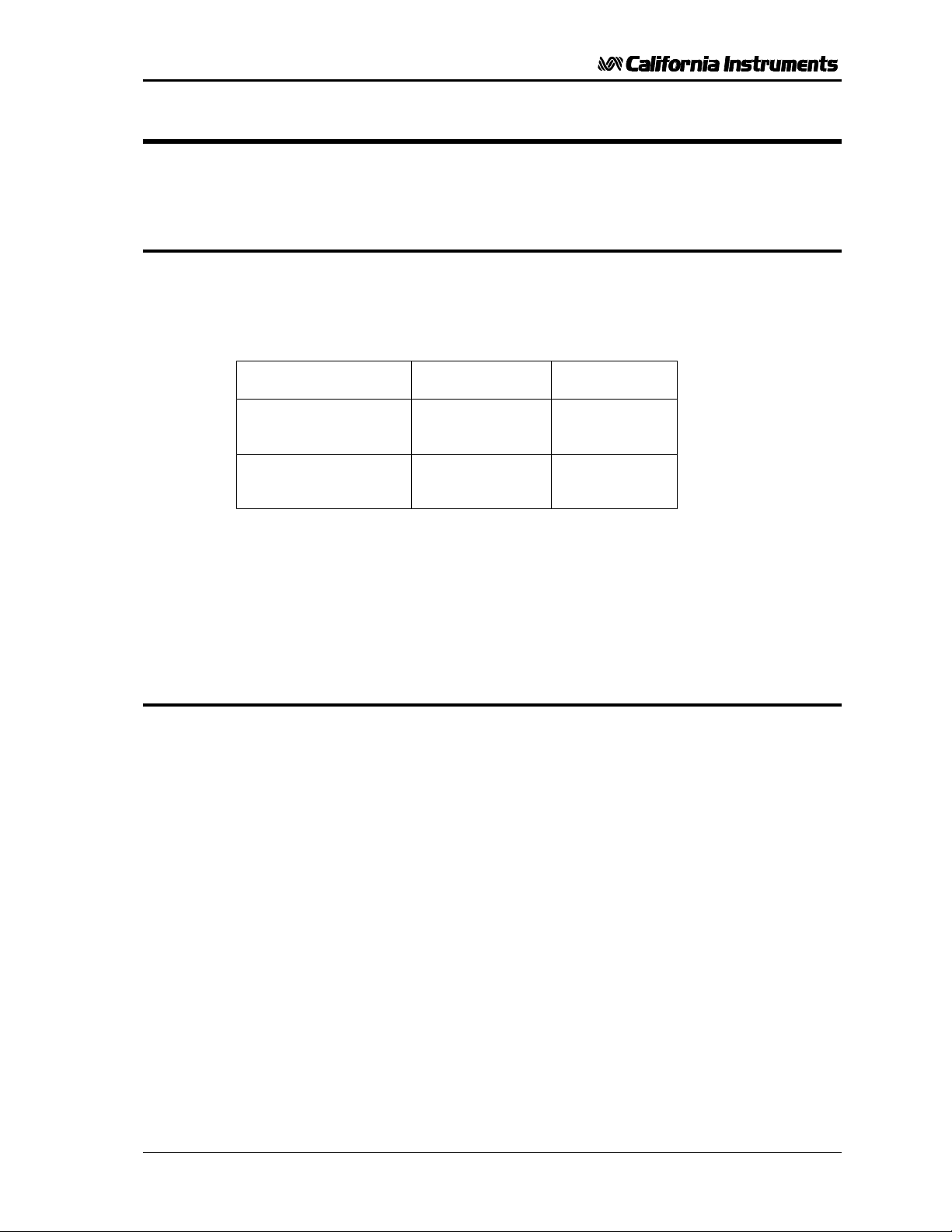
Model Voltage ranges Max. Current
351TL 135 V
270 V
251TL 135 V
270 V
The output voltage High and Low terminals are isolated from the chassis, and earth ground.
The AC input can be either 105 V
91 V
RMS
to 109 V
RMS
or 182 V
RMS
to 125 V
RMS
to 217 V
RMS
Simple front panel controls enable the voltage, current limit and frequency to be changed.
An optional RS232C and IEEE 488 interface is available for applications that require remote
control and measurements.
1.2 Accessory Equipment/Rack Slides
General Devices Company Model C300-120-B308 rack slides (option -RMS) may be
attached to the sides of the power source using 10-32 X 3/8 flat head screws.
2.8 A
RMS
RMS
RMS
AC, 210 V
RMS
1.4 A
2.4 A
1.2 A
RMS
RMS
RMS
RMS
to 250 V
at 47 to 67 Hz line frequency.
RMS
AC,
TL Series November 2001 1
Page 11

User and Programming Manual - Rev C
This page intentionally left blank
2 November 2001 TL Series
Page 12

User and Programming Manual - Rev C
2 Specifications
All specifications at 23 ±5°C unless noted otherwise.
2.1 Electrical
Input
Line Voltage:
115 V
230 V
100 V
200 V
nominal, 105 V
RMS
nominal, 210 V
RMS
nominal, 91 V
RMS
nominal, 182 V
RMS
RMS
RMS
RMS
RMS
to 125 V
to 250 V
to 109 V
to 217 V
RMS
RMS
RMS
RMS
AC
AC
Unit must be configured for correct Line input voltage.
Line Current: 9 A
maximum, line voltage = 115 VAC, full-load
RMS
PF = 0.7
Inrush Current:
150 A
75 A
for 115V line
pk
for 230V line
pk
Input power factor: 0.7 at full-load and 115 VAC input
Line Frequency: 47 Hz - 67 Hz
Isolation Voltage: Input to output = 2300 VAC, input to chassis = 1350 VAC
Output
Parameter Specification
Voltage
Range 0 to 135 V
or 270 V
RMS
(standard ranges)
RMS
Resolution 0.1 volt
Accuracy
± 0.1 % of calibrated range, 45 Hz - 100 Hz
± 0.2 % of calibrated range, 100 Hz - 5000 Hz
± 0.3 % of calibrated range, 5000 Hz - 8000 Hz
Load Regulation 0.1 % of FS. Add 0.05% above 2000 Hz
TL Series November 2001 3
Page 13

User and Programming Manual - Rev C
Parameter Specification
External Sense Will compensate for up to 5% of voltage drop up to 2kHz
Line Regulation 0.02 % of FS
Settling time From start of voltage change from 5.0 V
voltage to within 2% of final value:
Distortion (THD
into linear load)
<0.5 % maximum 45 to 499 Hz
<1.0 % above 500 Hz
<2.0% 1000 to 8000Hz
DC Offset voltage AC Coupled transformer output
Output noise -73 db typical
( 20 kHz to 1 MHz at full load )
Temperature
± 0.02 % of full scale per degree C
coefficient:
Stability (24 hours) ± 0.015 % of full scale under constant load, line and
temperature
Total Power
PT = 0.7
351TL: 350 VA from 90 to 100% of V range
251TL: 250 VA from 78 to 100% of V range
Current (Refer to Figure 2-1 for derating)
Output
V Range
351TL
251TL
RMS
No load: 16 msec
Full load: 300 msec
(16 msec to within 15 % of final value)
Amps rms Amps peak
135
270
135
270
2.8
1.4
2.4
1.2
or higher
6
3
6
3
Adjustable Limit 0.0 to Maximum available RMS current for selected
voltage range.
Accuracy Programmed value + 5, -0 % of maximum RMS current
4 November 2001 TL Series
Page 14

User and Programming Manual - Rev C
Parameter Specification
Frequency
Range 351TL 16.0 - 8000 Hz
Resolution 0.01 Hz from 16.00 to 80.00 Hz
Accuracy
Maximum output voltage available from 45 Hz.
0.1 Hz from 80.1 Hz to 800.0 Hz
1 Hz from 801 Hz to 8000 Hz
± 0.02% of programmed value
Temperature
± 5 ppm per degree Celsius
coefficient
Stability ± 15 ppm per year
Figure 2-1: Output Power Rating as a Function of Voltage and Load PF
TL Series November 2001 5
Page 15

User and Programming Manual - Rev C
2.2 Measurements [Option]
Parameter Specification Unit
True RMS Current
Available on standard unit.
Range 0.000 - 4.000 A
Accuracy 0.2 % FS + 0.3 % reading
Resolution 0.001 A
Temp
Coefficients
Peak Current Requires Option -OP1
Range 0.00 – 12.00 A
Accuracy 0.5 % FS + 0.5 % reading
Resolution 0.01 A
Crest Factor
Available over bus only. Requires interface Option -OP1
Range 0.00 - 4.00
Accuracy 0.05
Resolution 0.01
True RMS Voltage Standard Unit: Available over bus only.
-OP1 option: Front Panel and bus.
Range 0.0 - 300.0 V
Accuracy 0.1 % FS + 0.05 % reading
Resolution 0.1 V
Temp
Coefficients
Real Power Requires Option -OP1
Range 0 - 400.0 W
Accuracy 0.2 % FS + 0.5 % reading
Resolution 0.2 W
Temp
Coefficients
Apparent Power
Available over bus only. Requires -OP1 option
Range (Remote only) 0 - 400.0 VA
Accuracy 0.3 % FS + 0.8 % reading
Resolution 2 VA
Power Factor
Requires -OP1 option
Range 0.00 - 1.00
Resolution 0..01
0.016
0.05
0.06
RMS
RMS
% FS / °C
PEAK
PEAK
RMS
RMS
V / °C
% FS /°C
6 November 2001 TL Series
Page 16

User and Programming Manual - Rev C
2.3 System Specification
Parameter Specification
Setup storage Eight non volatile front panel setup registers available through
interface. Power on setting register available from front panel.
Interface (Option package -OP1 required)
RS-232C Bi-directional serial interface
Rear panel connector: 9 pin D shell
Handshake: CTS, RTS
Data bits: 8
Stop bits: 1
Parity: None
Baud rate: 19200
Command syntax: IEEE 488.2 commands and SCPI
IEEE-488 GPIB Interface
Rear panel connector: 24 pin D-shell
IEEE address: set using dip switch on rear panel from
0 to 31
IEEE functions: SH1, AH1, T8, L4, RL2, SRQ 0, PP 0,
DC 0, DT 0, C0
Terminators: LF, CRLF, EOI
Command syntax: IEEE 488.2 commands and SCPI
Remote Inhibit (Option package -OP1 required)
Rear panel connector: BNC
Input Contact closure to ground or logic low TTL
signal required to turn off output.
Automatic recovery when RI signal is
removed.
Function Strobe (Option package -OP1 required)
Rear panel connector: BNC
Output Active low TTL signal. Signal driven low for
approximately 400 µsec any time output
voltage or frequency programmed value
changes. Signal level may be changed by
removing jumpers to open collector.
TL Series November 2001 7
Page 17

User and Programming Manual - Rev C
2.4 Unit Protection
Parameter Specification
Input Overcurrent: Electronic current limit with circuit breaker.
Transients: Surge protection to withstand EN50082-1 (IEC 801-4, 5) levels.
Output Overcurrent: Constant current operation. (Standard)
0.1 Second shutdown (constant voltage mode Option)
Output Short Circuit: Peak current limit.
Shutdown (constant voltage mode Option).
Overtemperature: Automatic shutdown.
2.5 Mechanical
Parameter Specification
Dimensions: Height Width Depth Unit
13.26 48.26 56.62 cm
5.22 19 22.29 inches
Unit Weight: 34 Kg / 75 lbs
Material: Steel chassis and panels.
Aluminum cover.
Finish: Yellow iridite, painted semi-gloss polyurethane
Cooling: Fan cooled with air intake on the sides and exhaust to the rear.
Internal Construction: Modular sub assemblies.
Chassis Slides: P/N 210960 / Option -RMS
General Devices Model CTS-1-20-B307-2
Front Panel Mounted Output Connection:
Wonpro Universal outlet socket (option -SKT)
Rear Panel Mounted Connectors:
RS232C I/F DB 9
IEEE-488 I/F D-shell 24 pin
Remote Inhibit BNC (requires -OP1 option package)
Function Strobe BNC (requires -OP1 option package)
AC Output Amp 1-480705-1
External Sense Amp 1-480705-1
Line Input Kulka 9-85-3 Terminal block
8 November 2001 TL Series
Page 18

User and Programming Manual - Rev C
2.6 Environmental
Parameter Specification
Operating Temp: 0 degrees to + 40 degrees Celsius.
Storage Temp: - 40 degrees to + 85 degrees Celsius.
Humidity:
Altitude Operating: 15000 feet / 6000 meters maximum.
Creepage and
Clearance:
Insulation: Rated to Installation Category (Overvoltage Category) II
Vibration: Designed to meet NSTA 1A transportation levels.
Shock: Designed to meet NSTA 1A transportation levels.
2.7 Regulatory
Parameter Specification
Electromagnetic
Emissions and
Immunity:
Acoustic Noise: 65 dBA maximum at 0% to 50% load, 75 dBA maximum greater
Operating: ≤ 90% RH up to 40° C., non condensing
Storage: ≤ 90% RH up to 40° C, ≤75% RH up to 70° C.
VA Power: Full VA power output :0 - 6000 feet / 0 - 2000
meters.
Derate VA power 5 % per 1000 feet from 6000 to
15000 feet / 2000 to 6000 meters.
Rated for Pollution Degree 2.
Designed to EN50081-1 and EN50082-1 European Emissions
and Immunity standards as required for the “CE” marking.
than 50% load to 100% load. Measured at one meter.
Safety: Designed to EN61010-1 European safety standards as required
for the “CE” marking.
Remote Control
TL Series November 2001 9
Page 19

User and Programming Manual - Rev C
2.8 Front Panel Controls
Parameter Specification
Controls: Shuttle knobs:
Allows continuous change of Voltage, Frequency and Current
limit. Voltage change is inactive on single voltage range
configuration units.
Function keys:
Controls Output state, Voltage range and Display mode.
Displays: Two, 4 digits, 0.5” LCD display. For viewing programmed voltage,
frequency, current limit and for displaying measured current.
Status Indicators: 10 LEDs to indicate:
REMOTE, FAULT, OUTPUT (ON/OFF), VOLTAGE RANGE
HIGH, VOLTAGE RANGE AUTO
FREQUENCY, CURRENT, PEAK CURRENT, POWER, POWER
FACTOR DISPLAY MODES (Refer to paragraph 4.1.2).
2.9 Available Options
Option Description
-OP1 Option package 1 includes:
-RMS Rack mount slides
-SKT Universal front panel dual outlet socket.
-EXT Removes controller and allows external oscillator input.
1
• Measurement Functions
• Combined IEEE-488 / RS232C interface.
• Remote Inhibit Input
• Function Strobe Output
P/N 211045 / Option -RMS
General Devices Model C300S-120-B308
1
Additional options may have been made available since this manual revision. Installed options are listed on
the power source’s type sticker. A manual addendum may be issued for new options not covered by this
manual.
10 November 2001 TL Series
Page 20

User and Programming Manual - Rev C
3 Installation and Functional Test
3.1 Unpacking
Inspect the unit for any possible shipping damage immediately upon receipt. If damage is
evident, notify the carrier. DO NOT return an instrument to the factory without prior
approval. Do not destroy the packing container until the unit has been inspected for damage
in shipment.
3.2 Power Requirements
The AC Power System has been designed to operate from a single phase AC line voltage.
The nominal operating voltage is 100V, 115V, 200V or 230V line input. The Power Source
line input setting is shown on the type sticker located on the rear panel.
Figure 3-1: Model 251TL / 351TL AC Power Source
WARNING: Do not connect the unit to a 400-480 service, as the result will be a severely
damaged unit.
Do not connect the unit to AC line input unless the nominal line input settings
match those of the available AC line voltage.
TL Series November 2001 11
Page 21

User and Programming Manual - Rev C
3.2.1 AC Line Voltage
The AC Power Source has been designed to operate from either of the following AC line
voltage ranges:
1) 91 to 109 V
2) 82 to 217 V
3) 105 to 125 V
4) 210 to 250 V
RMS
RMS
RMS
RMS
CAUTION: The AC Power Source will be damaged if it is operated at an input voltage
that is outside its configured input range.
The input voltage range is set at the factory. Section 3.3 gives the procedure to change the
input voltage range. The location for connection of the INPUT line is shown in Figure 3-2.
3.2.2 Line Frequency Operating Range
The AC Power Source has been designed to operate with a line frequency from 47Hz to
67 Hz.
3.2.3 Input Power
The input power to the AC Power Source depends upon line and load conditions and may be
as high as 1000 watts.
Figure 3-2: Rear Panel View
12 November 2001 TL Series
Page 22

User and Programming Manual - Rev C
4
5
3.3 Input Voltage Range Selection
WARNING: The line voltage is present in certain sections of this Power Source.
DEATH: On contact may result if personnel fail to observe safety precautions.
Do not touch electric circuits when power is applied. Servicing should
only be performed by trained personnel.
The input voltage range is configured by changing the taps on the input transformer. See
Figure 3-3 or Figure 3-4 for the location of the jumpers and input wires.
3.3.1 Voltage Range Configuration (105 – 125 V)
In order to change the voltage range configuration:
1. Turn off the input circuit breaker.
2. Disconnect AC input power to the source by unplugging the power cord.
3. Remove the AC Power Source top cover by removing (14) #6-32 x 5/16” FLH
screws. There are 7 screws on the sides and 7 screws on the top that hold the
cover.
Remove the (2) #6-32 x 1” PHN screws and lock washers that hold the amplifier near
the outside panel.
Remove the (2) #6-32 x 3/8” PHN screws and lock washers located near the
connector, attaching the red insulator to the center bracket.
The line input voltage range is set by the configuration of the Input Transformer, T1. To
configure T1 for the 105-125 volt range, make the following connections to T1 (refer to
Figure 3-3) :
Jumper terminals 1 and 4.
Jumper terminals 3 and 6.
Connect the input line from the Circuit Breaker to Terminals 1 and 6.
TL Series November 2001 13
Page 23

User and Programming Manual - Rev C
Figure 3-3: Connections to T1 for 105 - 125V Line Input
14 November 2001 TL Series
Page 24

User and Programming Manual - Rev C
3.3.2 High Input Voltage Range Configuration (210 – 250 V)
In order to change the voltage range configuration:
1. Turn off the input circuit breaker.
2. Disconnect AC input power at TB1.
3. Remove the AC Power Source top cover by removing (14) #6-32 x 5/16” FLH
screws. There are a total of 7 screws on the sides and another 7 screws on the top
that secure the top cover.
The line input voltage range is set by the configuration of the Input Transformer, T1. To
configure T1 for the 210-250 volt range, make the following connections to T1 (refer to
Figure 3-4) :
Jumper terminals 3 and 4.
Connect the input line from the Circuit Breaker to Terminals 1 and 6.
Remove all other connections to Terminals 1 through 6.
TL Series November 2001 15
Page 25

User and Programming Manual - Rev C
Figure 3-4: Connections to T1 for 210 - 250V Line Input
16 November 2001 TL Series
Page 26

User and Programming Manual - Rev C
3.4 Mechanical Installation
The power source has been designed for rack mounting in a standard 19 inch rack. The unit
must be supported from the sides with optional rack slides. See Accessory Equipment/Rack
Slides in Section 1.2. The cooling fan at the rear of the unit must be free of any obstructions
which would interfere with the flow of air. A 2.5 inch (6.35cm) clearance should be
maintained between the rear of the unit and the rear panel of the mounting cabinet. Keep in
mind that adequate ventilation of the mounting cabinet must be maintained for sufficient
cooling of the power source. Use louvered side panels, and/or perforated rear panels to
assure adequate airflow. Also, the air intake holes on the sides of the power source must not
be obstructed when mounted inside cabinet. See Figure 3-1.
3.5 Input Wiring
The AC Power Source must be operated from a three-wire single-phase service. The mains
source must have a current rating greater than or equal to 10 A for the low input range. Use
the supplied safety cover/strain relief when connecting the input wires to the power source.
Refer to Figure 3-2 for the input power connections. When connecting the input wires to
input terminal block, make sure the safety grounding wire from the strain relief grommet is
longer than the Line and Neutral wire so that the ground wire will be the last one to take any
strain. For low-range input operation (115V) we recommend #12 AWG input wires as a
minimum. For high-range input operation (230V) #14AWG is recommended. For European
applications (230V), the following input cordset may also be used:
Panel Components # 86518030 Rated 16A, 250V, 70° C, 3x 1.5mm² conductor size. VDE
approved. Install as described above for discreet wiring.
3.6 Output Connections
The output terminal block is located at the rear of the power source or on the front panel with
Option -SKT. All load connections must be made on the rear panel terminal block or from
the front panel socket if the -SKT Option is installed. The remote sense inputs are normally
jumpered directly to the adjacent power output pins on the output connector. If the sense
terminals are not connected to the power output pins, the output voltage may rise significantly
above the programmed value. When connecting the output wires, use the supplied safety
cover/strain relief and mount over the output connector. Also mount the supplied snap-on
ferrite filter around the output wiring between the output terminals and the strain relief
grommet. Enclose ferrite filter with the safety cover.
If the load is a significant distance from the output terminal strip it may be desirable to sense
the output voltage directly at the load. If remote sensing is to be used, then the size of the
output power wiring must be heavy enough to prevent a voltage difference greater than 7% of
the programmed value from the power output pins to the sense input pins.
The Remote Sense inputs must be connected or an output voltage 7% higher than the
programmed output will be generated. If the Power Source is configured for constant
voltage, a fault will be generated.
TL Series November 2001 17
Page 27

User and Programming Manual - Rev C
3.7 Output Voltage Ranges
The standard 351TL AC power source has two output voltage ranges 0-135 VAC and
0-270 VAC. The operator may switch from one range to the other at will with no special
precautions except to remember that the output voltage will go to zero voltage whenever a
range change takes place.
Certain options available on the 351TL series may result in different voltage range values or
a single voltage range only. Certain models may be ordered with a single voltage range only.
On single voltage range units, the Range change button has no function and the LED
indicator is not used.
351TL AC power source models with dual voltage ranges offer an auto voltage range change
mode. In this mode, the voltage range is automatically changed when the user sets a
voltage above 135 or below 131 V
The AUTO mode can be selected by pressing the range change button until the AUTO mode
LED illuminates. To take the AC power source out of the AUTO voltage range mode, press
the Voltage range button briefly. This will put the unit in the present range but takes it out of
auto mode.
RMS
.
Note: Even in AUTO mode, the output temporarily goes to zero volts when a
voltage range change occurs. If this is not acceptable, the AC source
should be operated in the high voltage range only and not in AUTO
mode.
18 November 2001 TL Series
Page 28

User and Programming Manual - Rev C
3.8 Functional Test
CAUTION: Work carefully when performing these tests - hazardous voltages are
present on the input and output during this test.
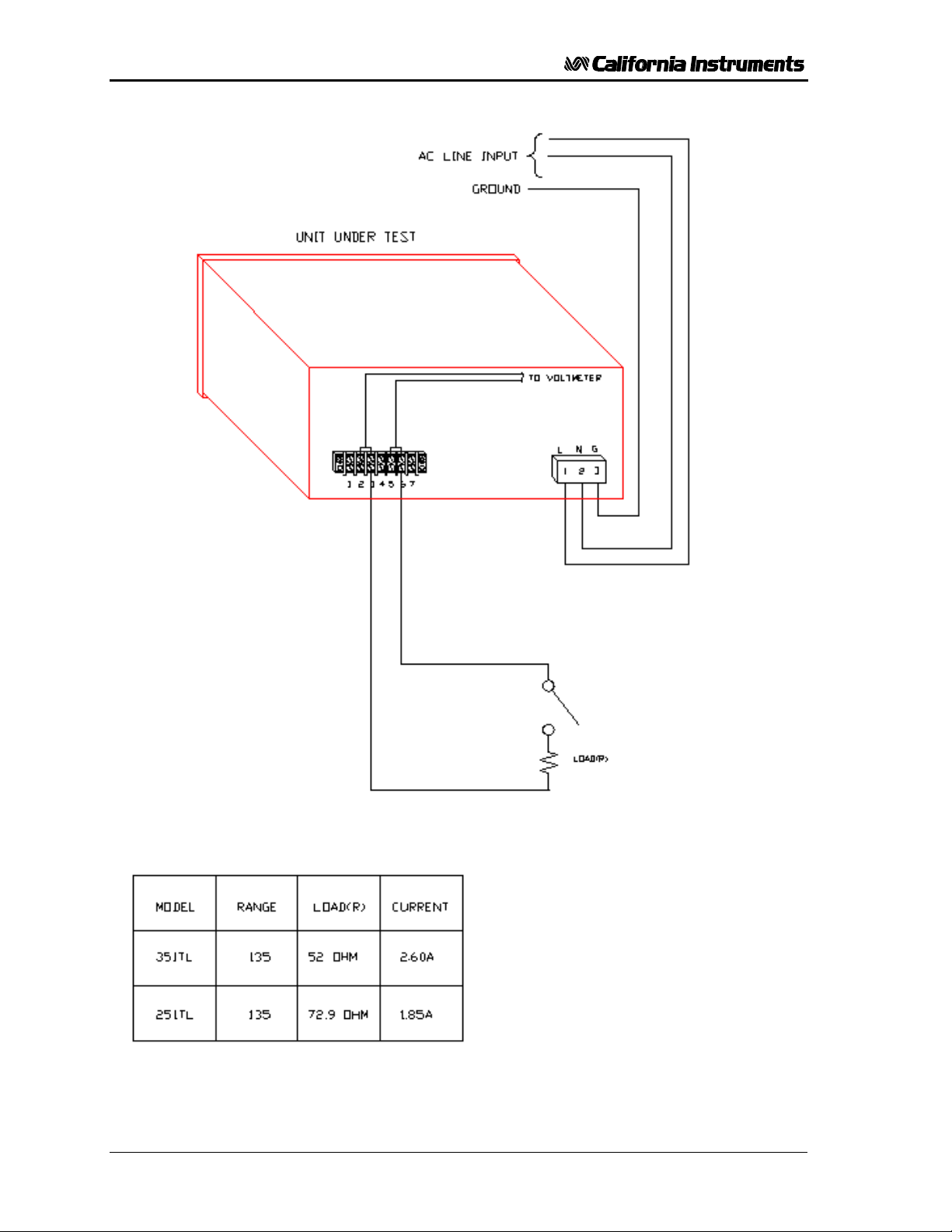
Refer to Figure 3-5 for the test set up. Use the following load resistor values:
Model Voltage Range Resistor Current (A
351TL 135
270
251TL 135
270
52 Ω
208 Ω
72.9 Ω
292 Ω
2.60
1.30
1.85
.92
RMS
)
1. Connect an oscilloscope, voltmeter and/or distortion analyzer to the AC source output at
the rear panel output terminal.
2. Connect the AC power input voltage connections to the AC source input terminals.
Connect the sense input to the adjacent power pin on the rear panel connector. Turn on
the power switch located at the rear panel.
3. Verify that the front panel LCD display reads out the initial start up voltage and frequency.
4. Select the low voltage range. Set the frequency to 60 Hz with the right shuttle. Select the
current function with the Frequency/Current selector. Set the current limit to the
maximum value using the right shuttle. Set the output voltage to 135V with the left
shuttle.
5. Enable the output by pressing the output “on/off” button in the top right of the front panel.
The green LED above the button will illuminate when the output is on. The output should
be a clean 135V AC sinewave having less than 0.5 % distortion.
6. Apply full load (refer to table on Figure 3-5) to the output of the source and verify the
output remains within 0.05 % of the initial 135V . The output should still be clean and the
distortion should still be less than 0.5 % at 60 Hz.
7. Using the right shuttle set the output current limit value to 2 amps (1 amp for the 251TL).
If the unit is configured for Constant Current mode, the system should go into current
limit and reduce the output voltage. This may create additional distortion on the output
voltage. If the unit is configured for Constant Voltage mode (factory default), an error
message will appear on the display (err. -300) that indicates an output fault condition and
the output will go off. Return the current value to the maximum current and disconnect
the load.
8. Repeat steps 4 through 7 but set the output for the following: Hi voltage range and the
current limit to maximum value. Refer to the table above for the relevant resistor values.
For units that are factory configured with a single voltage range, these steps do not have
to be repeated.
In the event the power source does not pass the functional test, refer to the calibration
procedure in Section 6 or call California Instrument’s customer satisfaction department for
further assistance.
TL Series November 2001 19
Page 29
User and Programming Manual - Rev C
Figure 3-5: Test Setup 351TL
20 November 2001 TL Series
Page 30

User and Programming Manual - Rev C
3.9 Current Limit - Modes of Operation
When the Power Source is shipped from the factory, it is configured for the Constant Current
Mode of operation. This mode means if the load current exceeds the programmed Current
Limit value, the output current will continue at the programmed value.
The Power Source can be configured to operate in the Constant Voltage mode. In this mode
of operation, if the load current exceeds the Current Limit value, the output voltage will
default with the output relay open. The Constant Voltage mode is only usable if the default
voltage is set for 5.0 volts. If the default is any other voltage, the power source may display a
fault at power up.
To configure the Power Source, remove the input line voltage connection from the rear
panel. Remove the top cover. Install jumpers W1 and W2 on the front panel controller.
Reinstall the top cover.
TL Series November 2001 21
Page 31

User and Programming Manual - Rev C
This page intentionally left blank
22 November 2001 TL Series
Page 32
User and Programming Manual - Rev C
4 Front Panel Operation
4.1 Functional Controls
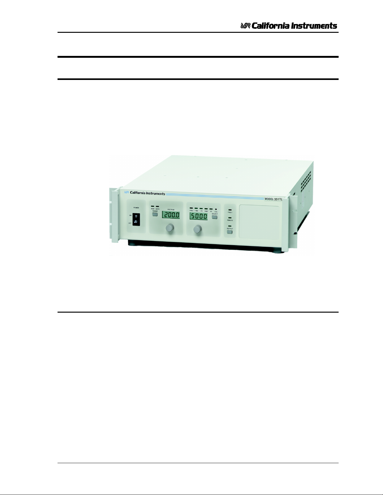
The front panel can be divided in a small number of functional areas:
• Output Sockets
• Status Indicator lights
• Shuttle knobs
• LCD display
• Button controls
Figure 4-1: Front Panel View
4.1.1 Dual Outlet Socket (Option -SKT)
A set of two universal output sockets may be located on the right side of the front panel. It
provides connection to the load from the AC source. The rear panel provides an output
terminal block for the AC source output which is always available. If the optional front panel
sockets are installed, output is present at both the front (Figure 4-1) and the rear panel
(Figure 3-2) output terminals.
Note: Even if the front panel sockets are used to connect the load, the external voltage
sense inputs must be connected. If it is impractical to connect the voltage sense lines at the
load, they may be connected at the rear panel output terminal block.
TL Series November 2001 23
Page 33

User and Programming Manual - Rev C
4.1.2 Status Indicator Lights
Ten LED status indicators are located directly above the LCD display. These LED’s
correspond to the following conditions:
REMOTE The REMOTE LED indicates that the unit is in remote
FAULT The FAULT LED indicates an overtemperature condition.
OUTPUT The Output LED indicates the status of the OUTPUT relay.
control mode. If the RS232C interface is used, the REMOTE
state can be enabled by the controller using the SYST:REM
command. Any time the REMOTE LED is lit, the front panel
of the RP Series unit is disabled. There is no LOCAL button
that allows the user to regain control of the front panel. The
SYST:LOC command will enable the front panel controls.
When using IEEE, the remote /local state is controlled by
the REN (Remote Enable) interface line.
Overtemperature is usually caused by poor air flow. Check
the air flow exhaust at the rear of the unit to make sure it is
not obstructed. If the power source is configured for
constant voltage, the indicator will illuminate for loss of
sense lines or an overload condition.
The output relay is controlled by the OUTPUT ON/OFF
button located directly below the LED. When the Output
LED is not lit, the output voltage is not present at the output
socket regardless of the voltage setting.
RANGE - HIGH The Range High LED indicates the selected output voltage
range. When it is illuminated it indicates the high voltage
range has been programmed. Any time the user switches
voltage ranges, the output is programmed to zero volt. The
output relay state is not changed however.
RANGE - AUTO The Range AUTO LED indicates the Power Source is in
auto ranging mode and will switch voltage range
automatically if the selected output voltage increments or
decrements through the low range voltage limit. (135 V
RMS
on standard units). During a range change, the output
voltage will be programmed to zero momentarily. Some
hysteresis is provided. See Figure 4-2.
FREQ Illuminates when the LCD display shows the programmed
frequency. In the calibration mode this indicator is not
illuminated for calibrating the output voltage. When it is
illuminated in the calibration mode the voltage measurement
can be calibrated.
I RMS Illuminates when the LCD displays shows the programmed
current limit, measured current values, or current
measurement calibration.
I PK Illuminates when the LCD displays shows the measured
peak current or peak current calibration. See Note.
PWR Illuminates when the LCD displays shows the measured
power or power calibration. See Note.
24 November 2001 TL Series
Page 34
User and Programming Manual - Rev C
PF Illuminates when the LCD displays shows the measured
Note: For peak current, power and power factor measurements, Option -OP1 is required. If
this option is not installed, these functions are not available and the SELECT button will only
toggle between FREQ and CURR modes.
power factor. It also illuminates in the calibration mode of
operation. In calibration mode, the PF LED is always lit in
combination with the measurement or output junction being
calibrated. In normal mode of operation, only one LED in
this group is on at a time. See Note.
270
135
131
0
Figure 4-2: Voltage Auto Range Switch Over Points
HIGH
Low to High switch-over
Hysteresis
High to Low switch-over
LOW
TL Series November 2001 25
Page 35

User and Programming Manual - Rev C
4.1.3 Shuttle knobs
Counter Clockwise
clockwise
DECREASE INCREASE
There are two shuttle knobs located below the LCD display which are used to change setup
parameters for voltage, frequency and current limit. The SELECT button selects the function
of the right shuttle. The right shuttle will control either the frequency or the current limit as
indicated by the indicator above the right LCD. The left shuttle always controls the voltage.
Figure 4-3: Shuttle Knob
4.1.4 Buttons
There are three function buttons for the Output Voltage Range, Output State and Shuttle
Mode. The following is a description of these buttons:
KEY DESCRIPTION
RANGE The RANGE button is used to change the voltage range
between the low range (0 to 135 volts) and high range (0 to
300, 270 or 230 volts). The LED above the switch will light
to indicate the high voltage range selection. The output
voltage will be reset to zero voltage after a range change. If
the Power Source is configured for a single voltage
range, this button is disabled.
The same button may be used to put the Power Source in
the AUTO voltage range change mode. This button toggles
from Lo, Auto, Hi and back to Lo. The AUTO LED will
illuminate when the AUTO range mode is enabled. While in
AUTO mode, the Power Source will switch to the high range
whenever a value larger than the low range limit is
programmed. Whenever a value below the low range limit is
programmed, the unit will switch to the low voltage range.
The output is momentarily interrupted when a range change
occurs.
To take the unit out of AUTO mode, press the RANGE
button again.
OUTPUT The OUTPUT button will toggle the output relay to connect
or disconnect the output. The LED above the button will
light when the output relay is closed. No output voltage will
be present when the OUTPUT button is off despite the level
of voltage programmed.
26 November 2001 TL Series
Page 36

User and Programming Manual - Rev C
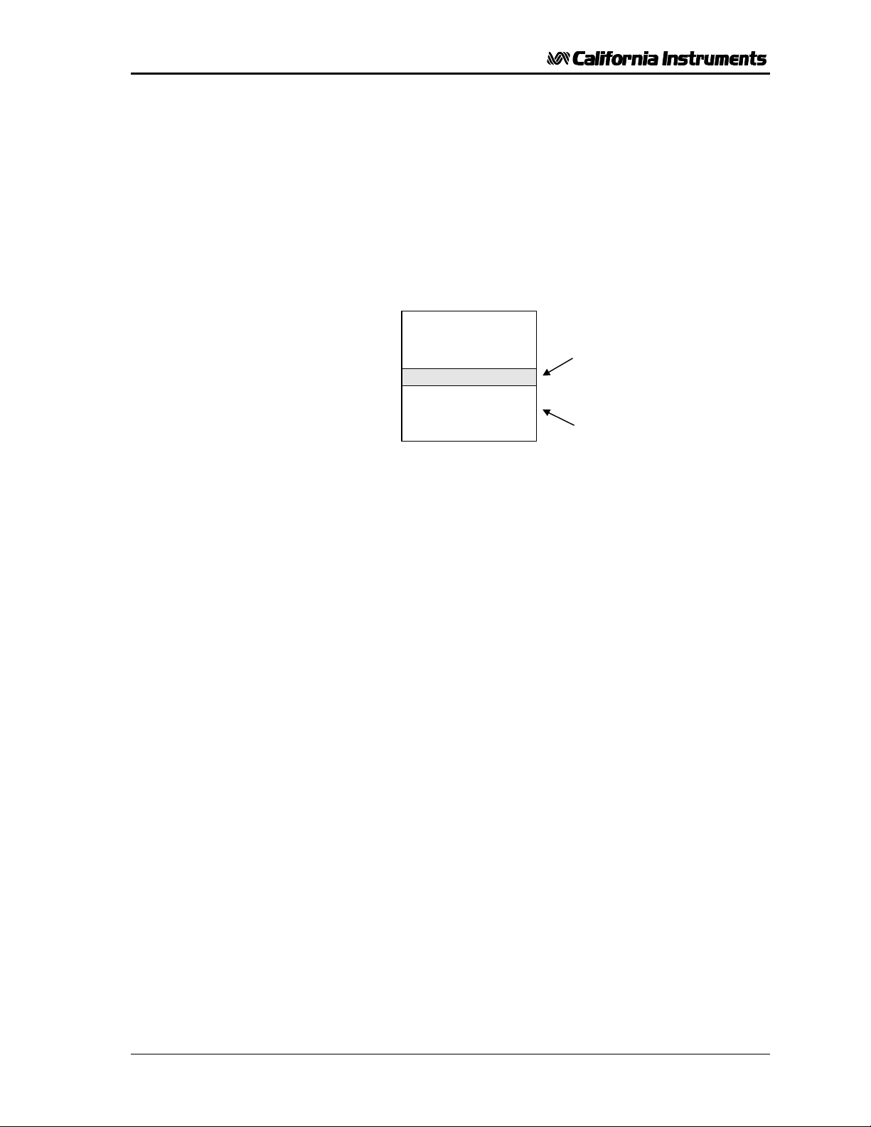
SELECT The SELECT button selects the function of the right Shuttle
(CAL) There is a switch behind this hole in the front panel. When
knob and the LCD display. The Shuttle will control the
output frequency and the display will show the program
frequency value when the mode selection is frequency. The
Shuttle knob will program the current limit and the display
will show its value in the current mode. The display will
revert back to showing the measured current after 3
seconds from the last movement of the shuttle.
The SELECT button also allows selection of the desired
measurement function readout. Available selections are:
• Current (Also puts the shuttle in Current Limit set mode)
• Peak Current
• Power
• Power Factor
Measurements are updated 4 times per second. The
display mode is indicated by the LED’s above the LCD
display. Note that voltage measurements are available
through the Voltage LCD.
the switch is depressed with the proper tool, the PF indicator
will illuminate to indicate the calibration mode has been
selected. The table below shows the calibration mode LED
indications after the (CAL) button is depressed.
4.1.5 LCD Displays
Settings and measurements are shown on two 4 digit, 7 segment displays. The voltage
display shows the programmed voltage as the user turns the left knob. After releasing the
knob for about 3 seconds, this display reverts back to displaying the measured output
voltage. The right hand LCD display is a multi purpose display. For setup purposes, it
displays either Frequency or Current limit settings. After about 3 seconds on inactivity, this
display switches to the selected measurement parameter. The SELECT button will define
the operating mode or the selected measurement parameter for the right hand display.
CALIBRATE
Output voltage PF only
Voltage measurement PF and FREQ
Current measurement PF and IRMS
Peak current measurement PF and IPK
Power measurement PF and PWR
INDICATORS
ILLUMINATED
TL Series November 2001 27
Page 37

User and Programming Manual - Rev C
4.2 How to Examples...
This section covers some common tasks that are often performed with an AC power source.
These examples are written in a How to... format and provide step by step instructions on
how to set up the AC Source for a specific task.
4.2.1 Set the Output
Output parameters are Voltage, Frequency and Current Limit.
1. Disable the output by pressing the OUTPUT button. The LED above the button will turn
off.
2. Use the left shuttle to set the output voltage. Clockwise will increase the output, counter
clockwise will reduce the output. The display above the shuttle will show the voltage
setting.
3. Use the right shuttle to set the frequency and current limit. The SELECT button will
define the function of the shuttle and the display above it. The Frequency or Current LED
will turn on to indicate the function controlled by the right shuttle.
4. Enable the output by pressing the OUTPUT button.
4.2.2 Slew Output Values
The output parameters can be slewed using the shuttles.
1. Enable the output by pressing the OUTPUT button. The LED above it will turn on.
2. Use the left shuttle to set the output voltage. Clockwise will increase the output, counter
clockwise will reduce the output. The display above the shuttle will show the voltage
setting.
3. Use the right shuttle to set the frequency and current limit. The SELECT button will
define the function of the shuttle as indicated by the display above it. The LED’s located
above the display will indicate the selected function.
28 November 2001 TL Series
Page 38

User and Programming Manual - Rev C
4.2.3 Display Measurement Data
Measurements can be called up as follows:
1. For voltage, the left display always displays the measured output voltage unless the
knob is turned. As the knob is turned, the programmed voltage will be displayed
instead. After releasing the knob for about 3 seconds, the display reverts back to the
measured voltage.
2. All other measurements can be displayed by using the SELECT button to toggle
through the available measurements. The LED’s above the LCD indicate the current
selection. The knob only affects programmed frequency and current limit.
3. Moving the right shuttle knob will interrupt the select measurement and put the
display back in Current Limit adjust mode.
Note: For peak current, power and power factor measurements, Option -OP1 is required.
4.2.4 Change the Voltage
The voltage range can be changed as follows (If the Power Source is configured for a single
voltage range, this does not apply):
1. Press the RANGE button located in the upper left corner. The output voltage will
reset to 0 volts.
2. Use the left shuttle knob to set the output voltage.
The AUTO voltage range can be selected as follows:
3. Press the RANGE button located in the upper left corner. The AUTO LED will
illuminate. The AC source is now in Auto range mode. Turn the left shuttle knob to a
value above 135 V. The unit will switch to high range and the HIGH LED will
illuminate.
4. Turn the left shuttle knob to reduce the voltage to a value below 135 V. The AC
source will switch to the low voltage range and the HIGH LED will turn off.
To turn off the AUTO voltage range, proceed as follows:
5. Press the RANGE button. This puts the AC source back in normal mode. The
voltage range that was in effect does not change. The AUTO LED will turn off.
6. Press the RANGE button again to toggle voltage ranges.
TL Series November 2001 29
Page 39

User and Programming Manual - Rev C
4.2.5 Control the Output
The Output can be disabled or enabled using the ON/OFF button as follows:
1. Pressing the OUTPUT button when the output LED is on will open the AC source output
relay. The programmed voltage setting will remain at the last program value.
2. Pressing the OUTPUT button again will close the output relay and the output will revert to
the last programmed value.
4.2.6 Measure Peak Inrush Current (Requires -OP1 Option)
The peak current measurement function of the Power Source uses a sample and hold circuit
to track the highest peak current found until reset. The peak current sample and hold circuit
is reset any time the user toggles away from the peak current display mode to a different
measurement.
The peak inrush current for a unit under test can be measured using this function as follows:
1. Program the output to zero volts and open the output relay using the ON/OFF button.
2. Use the SELECT button to display the present peak current value.
3. Use the SELECT button again to toggle to any other measurement readout. This will
effectively reset the peak current sample and hold circuit to zero amps.
4. Use the left shuttle knob to set the voltage to the nominal supply voltage of the unit under
test.
5. Use the ON/OFF button to apply the programmed voltage to the unit under test.
6. Use the SELECT button to display the measured peak current value.
Note: The 351TL output is turned on at random phase angle. It may be
necessary to repeat this test to find the highest possible peak inrush
current demanded by the unit under test.
Phase angle control is available over the bus if the –OP1 option
package with IEEE-488/RS232C interface is installed.
30 November 2001 TL Series
Page 40
User and Programming Manual - Rev C
4.3 Setting the Power on Initialization Values
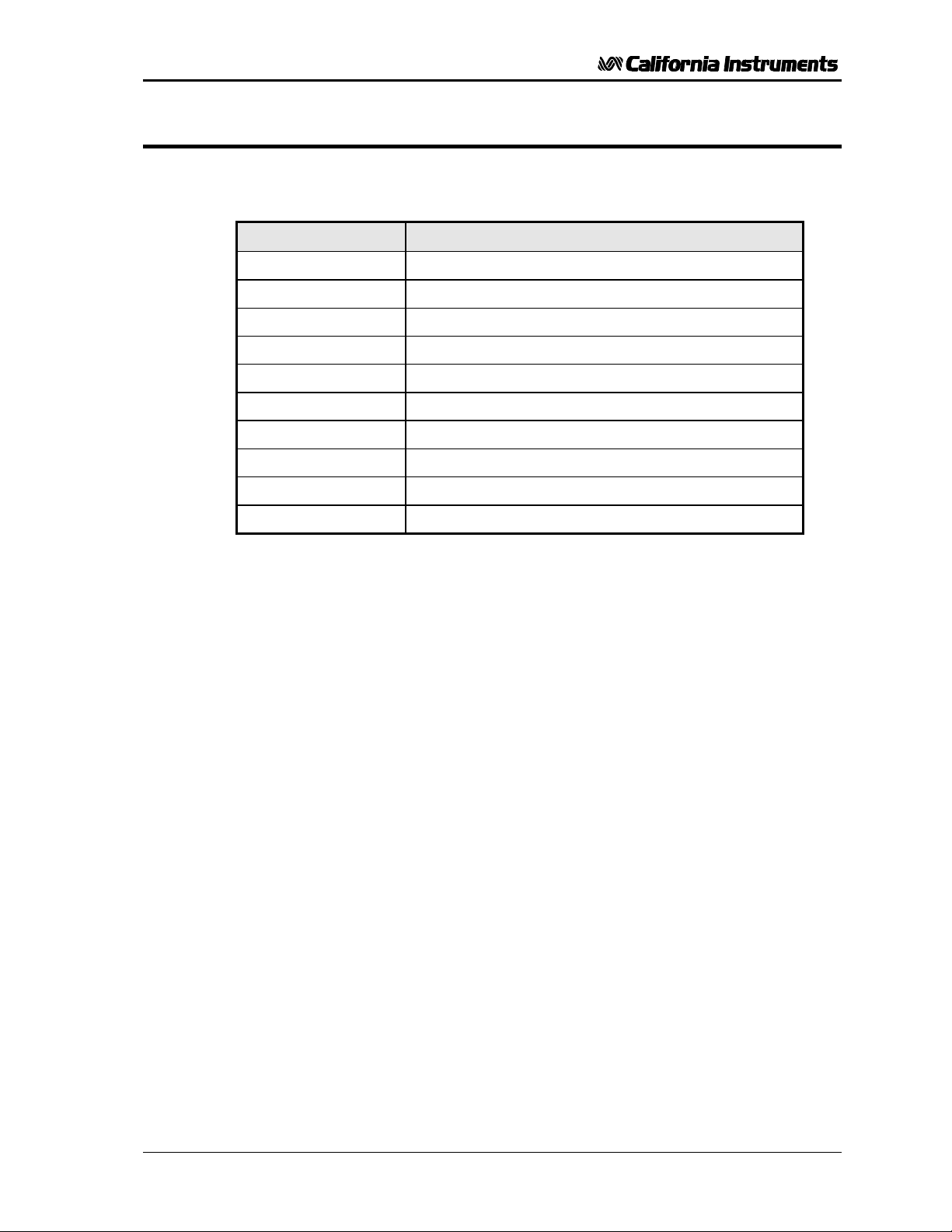
The Power Source is supplied with default factory settings when the unit is powered up. The
factory settings are:
Parameter Factory default setting
Voltage range Low
Auto Voltage Range OFF
Voltage 5.0 Volt
Frequency 60 Hz
Current limit 2.8 amps
Display mode Frequency
Output Relay state OFF
Output start state OFF
Output start phase 0 degrees
Local / Remote State Local. Front panel unlocked.
Table 4-1: Factory Default Power on Settings
It is possible to change the power on initialization values in one of two ways:
1. Using the optional RS232 or IEEE-488 interface and the supplied PGUI32 program.
2. Using the front panel.
To change the power on initialization values from the front panel, proceed as follows:
1. Set the unit up in the desired way from the front. (Range, voltage, frequency, current
limit, output relay state, display mode).
2. Press and hold the SELECT key (normally toggles LCD display mode). Make sure the
correct indicator LED is illuminated, e.g., FREQ to display voltage and frequency.
3. While holding the SELECT key, press the OUTPUT ON/OFF key. This will save the
present front panel settings in non volatile memory register (NVM) no 7 and assign this
register as the power on register.
4. Release both keys. Note that as step 2 is executed, the display mode will toggle . This
means the display mode after power up is different from how the unit was set up. To
avoid this, just toggle the display till one position before the desired power on mode first
and then execute steps 2-4.
5. This procedure can be repeated as often as needed by the user.
TL Series November 2001 31
Page 41
User and Programming Manual - Rev C
4.4 Current Limit Modes
The Power Source supports two modes of current limiting. In either mode, the end user can
set the RMS current level at which the current limit function will kick in. The available current
limit modes are:
Constant Current (CC) mode This is the default mode as supplied from the
Constant Voltage (CV) mode In this mode of operation, the output of the AC
factory. In this mode of operation, the output
voltage is automatically reduced by the AC power
source to maintain the set current. Once the
current drawn drops below the set limit value, the
voltage is increased again. No error message is
generated in this mode of operation. This mode
is suitable for starting up loads that require high
inrush currents but don’t need full nominal voltage
to run. (example AC motors).
source is turned off and the programmed voltage
is set to 0 volt as soon as the load current
exceeds the set current limit value. (Trip current).
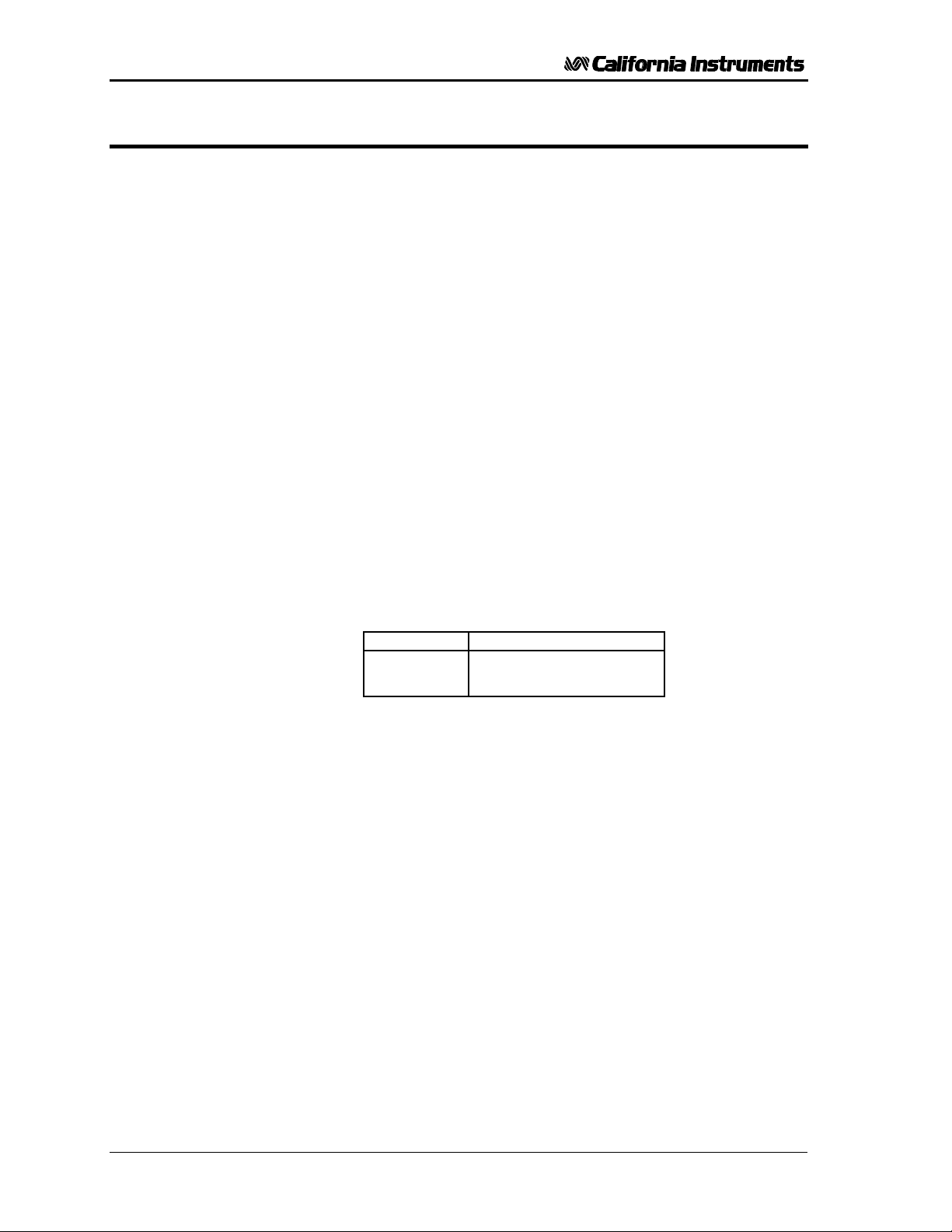
The selected current limit mode may be changed by moving a jumper on the AC power
source controller board. This requires that the AC source is disconnected from the AC line
and the top cover is removed. The current mode jumper is located at the top of the controller
board which is directly behind the front panel.
MODE JUMPERS
CC W1 and W2 Removed
CV W1 and W2 Installed
32 November 2001 TL Series
Page 42

User and Programming Manual - Rev C
4.5 Function Strobe [Option]
The Function Strobe (FS) is a TTL logic level signal provided at the rear panel of the Power
Source. This signal is synchronized to any voltage and frequency output changes of the AC
source and may be used to trigger external test equipment such as oscilloscopes.
Default mode of operation
The function strobe is an active low TTL output signal. Each sync pulse lasts approximately
400 µsec . The output changes on the falling edge of the function strobe output.
Alternative mode of operation
The function strobe output logic uses the GPIB interface DC supply to provide the required
logic levels. If the GPIB interface is connected to the user’s PC, excessive ground noise may
prevent the function strobe from operating correctly. If this is the case, the output mode of the
function strobe may be changed to provide an open collector output instead. In this case, the
end user has to provide an external DC power supply and pull-up. A 9 Volt DC battery may
be used for this purpose. Contact California Instruments’ service department for details on
changing the operation of the FS output.
4.6 Remote Inhibit [Option]
A Remote Inhibit BNC input is located on the rear panel of the Power Source if the -OP1
option was specified at the time of purchase. This input may be used to kill the AC source
output using an external control signal.
Default mode of operation
If the Remote Inhibit input is left unconnected, the output of the AC source can be turned on
using the ON/OFF button on the front panel or the appropriate bus command. To disable the
output relay, a logic low level or a contact closure needs to be present across the terminals of
the BNC (RI) connector.
Typical use of the RI input is in rack and stack systems where the RI input is wired to a
switch that detects removal of the rear panel. This input may also be used to simultaneously
shut down multiple AC power sources.
Note that the RI input has an internal pull up resistor to TTL logic high. When the RI input
cable is disconnected, the output will recover and the output relay will be closed
automatically.
TL Series November 2001 33
Page 43

User and Programming Manual - Rev C
This page intentionally left blank
34 November 2001 TL Series
Page 44

User and Programming Manual - Rev C
5 Principle of Operation
5.1 General
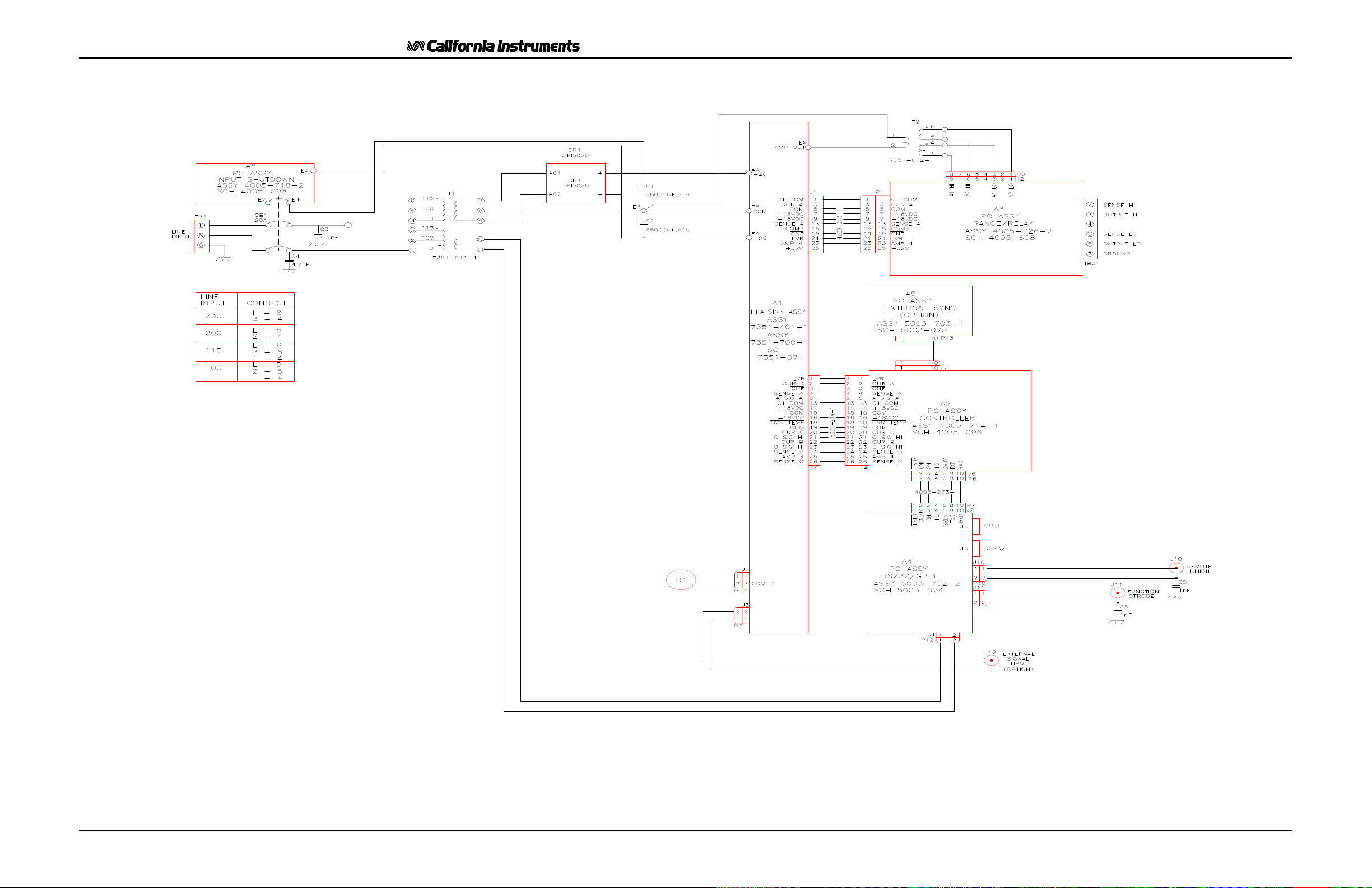
An explanation of the circuits in the AC Source is given in this section. Refer to block
diagram in Figure 5-1.
5.2 Overall Description
Input power at the rear panel is routed through the circuit breaker to the input transformer.
The DC supply outputs then go to the Amplifier, A1, then are directed to other modules.
The output of the transformer, T1, goes to a bridge rectifier and filter caps for a + and -28
supply.
The Programmable Controller Assembly, A2, generates the oscillator waveforms, power
source controls and measurement signals. The oscillator assembly is connected to the rest
of the power source through the Amplifier Board, A1.
The Amplifier Module, A1, takes its DC supply voltages directly from the DC supply. It gets
it's input signal from the Controller Board, A2. It produces the high power output for the
primary of the output transformer, T2. The output from the output transformer is connected
to the Range Relay Board, A3.
The Range Relay Board assembly configures the secondaries of the output transformers for
the correct output voltage range. The output from the AC Power Source is taken from the
Range Relay Board.
5.3 Input Power Supply
The Input Power Supply consists of transformer, T1, Bridge Rectifier OR1 and capacitors C1
and C2. The DC output from the supply connects to the Amplifier. The +28 VDC supply
connect to the Amplifier terminal E2. The -28 VDC supply connect to E3 and the common to
E4. The transformer also supplies the RS232/GPIB assembly with an isolated AC supply.
TL Series November 2001 35
Page 45

User and Programming Manual - Rev C
This page intentionally left blank
36 November 2001 TL Series
Page 46
User and Programming Manual - Rev C
TL Series November 2001 37
Figure 5-1: AC Power System Block Diagram
Page 47
User and Programming Manual - Rev C
This page intentionally left blank
38 November 2001 TL Series
Page 48

User and Programming Manual - Rev C
5.4 Range Relay Board
The Range Relay Board, Module Assembly A3, has all of the AC Power Source relays.
These relays are operated from +28 VDC. The output relay is controlled by the CNF Logic
Line. The range relay is controlled by the LVR line.
There is a current transformer on the Range Relay Board. This transformer generates an
AC voltage that is proportional to the output current. The current transformer burden resistor
has two different values for the two current measurement ranges. The relay for the
measurement ranges is controlled by the AMP 4 line.
The Range Relay Board also has an instrumentation amplifier. This amplifier is used to
remotely sense the output voltage. The signal from the instrumentation amplifier is
SENSE A.
5.5 Amplifier
The AC Power Source uses a linear amplifier for a low-noise, low distortion output. The
amplifier module is designated A1. The Amplifier assembly also acts as an interconnect
between the other board assemblies.
The Amplifier obtains its input signal from the Controller. A 5.0V RMS input signal will
generate a full-scale output voltage at the output of the AC Power Source and 11.5V RMS on
the primary of the output transformer.
The Amplifier requires ± 28 VDC. The ± 28 VDC supply comes from the DC input power
supply.
The Amplifier has a thermo-switch mounted on its heat sink. If the heat sink temperature
exceeds 80 degrees C, the amplifier shuts down and sends an OVT signal to the oscillator
module. Logic low on the OVT control line will cause the front panel FAULT indicator to be
illuminated. When the heatsink exceeds 45 degrees C, the fan speed will increase.
5.6 Controller Module
The Controller Module is designated A2. The module consists of one printed circuit
assembly. This assembly is interconnected to the Amplifier Board.
The Oscillator Module has the circuits to perform the following operations:
1. Generates the output voltage sinewave.
2. Interprets the Voltage, Frequency and Current limit commands from the front panel and
RS232/GRIB Board.
3. Attenuates the oscillator drive signal to operate in a constant current mode.
4. Measures the output voltage, current, peak current and power.
5. Performs voltage dropouts at a designated phase angle.
TL Series November 2001 39
Page 49

User and Programming Manual - Rev C
5.7 IEEE 488/ RS232 Interface [Option]
The 351TL can optionally be outfitted with a combined RS232C and IEEE 488 interface
board. This board assembly has opto-couplers for interface isolation.
The GPIB address for the AC source is selected by a DIP switch on the rear panel. Only one
interface can be active at any given time and must be selected using DIP switch position 6.
(Refer to Figure 8-2).
40 November 2001 TL Series
Page 50
User and Programming Manual - Rev C
CAUTION
THE INPUT LINE VOLTAGE IS PRESENT IN CERTAIN
SECTIONS OF THIS
POWER SOURCE. THIS EQUIPMENT GENERATES
POTENTIALLY LETHAL VOLTAGES.
DEATH
ON CONTACT MAY RESULT IF PERSONNEL FAIL TO
OBSERVE SAFETY PRECAUTIONS. DO NOT TOUCH
ELECTRONIC CIRCUITS WHEN POWER IS APPLIED.
TL Series November 2001 41
Page 51

User and Programming Manual - Rev C
This page intentionally left blank
42 November 2001 TL Series
Page 52
User and Programming Manual - Rev C
6 Calibration
Routine calibration should be performed every 12 months. Non-routine calibration is only
required if a related assembly is replaced or if the periodic calibration is unsuccessful.
Calibration can be performed through the front panel by putting the Power Source in
Calibration mode (CAL mode) or over the RS232C or IEEE-488 bus if the interface option is
installed. For bus calibration, the PGUI32 program may be used. Refer to the PGUI32 help
file supplied with the program for instructions on calibration over the remote control bus.
All routine calibrations can be performed without removing the top cover (Closed case
calibration).
6.1 Calibration Equipment
Digital Multimeter (DMM): Two (2) HP 34401A
100 milliohm Current Shunt: Isotek Model RUG-Z-R100-0.1 or equivalent
Load Bank: Various power load resistors will be needed
Model Range Current
max.
351TL 135 V 2.8 A
270 V 1.4 A
251TL 135 V 2.4 A
270 V 1.2 A
Table 6-1: Load Resistors and Current
Load
48.2 Ω
192.9 Ω
56.3 Ω
112.5 Ω
TL Series November 2001 43
Page 53
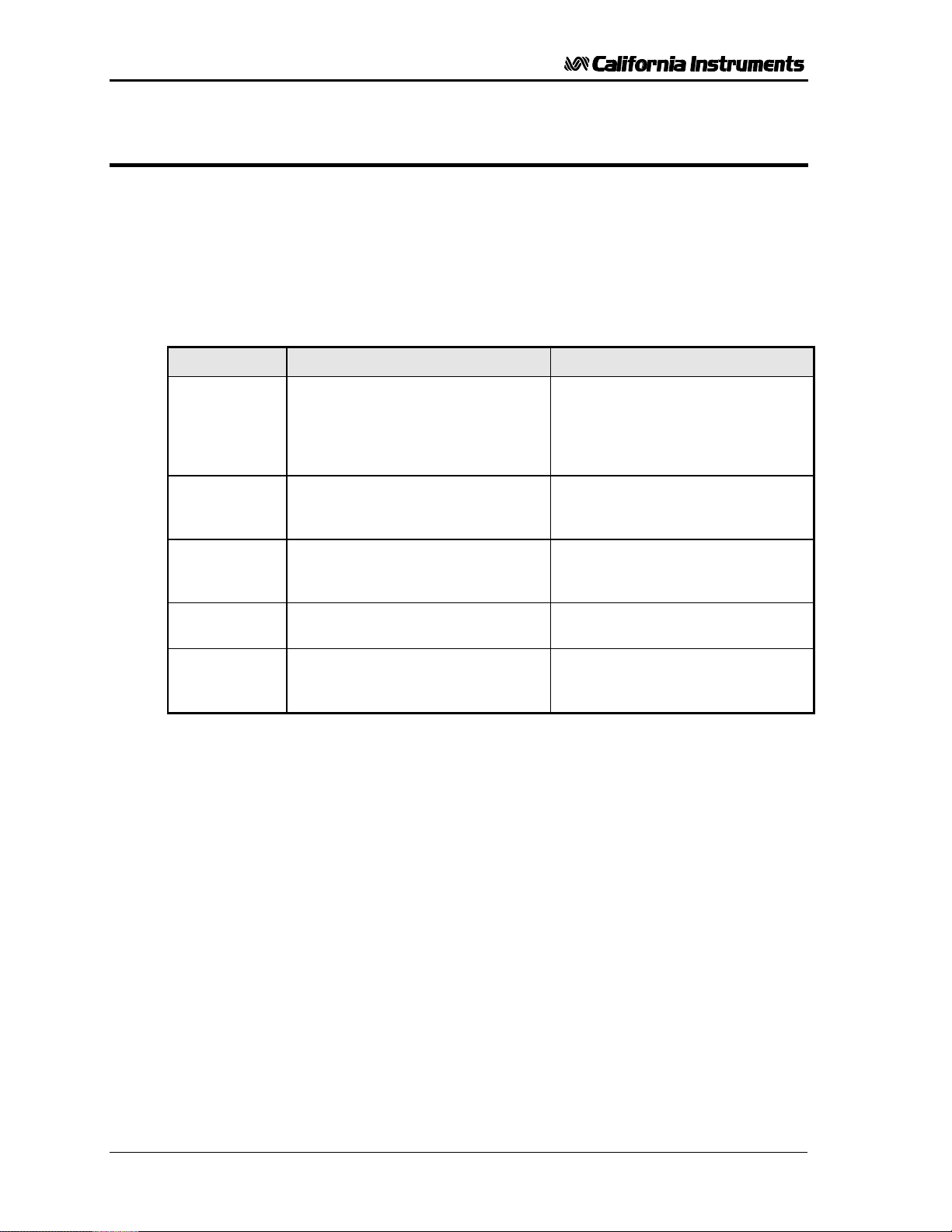
User and Programming Manual - Rev C
6.2 Selecting Calibration Mode
The Power Source can be placed in calibration mode (CAL mode) by depressing the
recessed CAL button located on the front panel using a pen or similar pointed object.
Depressing this button for a brief moment will place the Power Source in CAL mode,
indicated by the illumination of the PF LED. While in CAL mode, the front panel controls are
used to adjust the various calibration parameters. Both controls and status indicators take
on different functions while the unit is in CAL mode. The SELECT button is used to select
the various measurement parameters that can be calibrated in this mode. The following
status indications are in effect while in CAL mode:
Status LED CAL mode * (PF LED illuminated) Normal operating mode *
FREQ Indicates voltage measurement
calibration is selected.
If this LED is not lit while in CAL
mode, the Output Voltage
calibration mode is selected.
I RMS Indicates current measurement
calibration is selected.
I PK Indicates peak current
measurement calibration is
selected.
PWR Indicates power measurement
calibration is selected.
PF Indicates 351RP unit is in
calibration mode.
Table 6-2: CAL Mode Status LED Indicators
* Some measurement functions are optional and may not be available. The calibration mode
will only select measurement calibration for measurement functions that are installed.
Note that in normal mode of operation, at no time more than one of the measurement mode
selection LED’s are lit at the same time. In CAL mode however, the PF LED is always on, in
addition to one of the other four measurement selection LED’s or no other LED for output
voltage calibration.
Indicates frequency setting or
measurement is displayed on right
LCD.
Indicates current limit setting or
current measurement is displayed
on right LCD.
Indicates peak current
measurement is displayed on right
LCD.
Indicates power measurement is
displayed on right LCD.
Indicates power factor
measurement is displayed on right
LCD.
44 November 2001 TL Series
Page 54
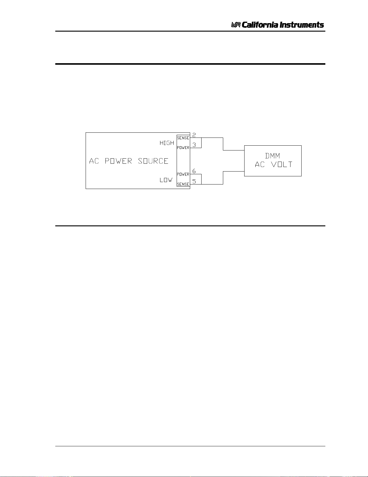
User and Programming Manual - Rev C
6.3 Routine Calibration
Setup:
Connect the test equipment to the power source as shown in Figure 6-1. The DMM can be
connected to the common output terminal at the rear of the unit.
Never connect the load wire to the SENSE terminal at the Rear Panel terminal strip. The
load must be connected to the POWER output terminal and a jumper between the
POWER and SENSE terminal. Always connect the external DVM to the SENSE terminal.
Figure 6-1: Test Equipment Hookup for Routine Output and Voltage Measurement Calibration
6.3.1 Output Voltage Calibration
1. Select the high voltage range. Set the output frequency to 400 Hz . Set the output voltage
to 240 volts.
2. Remove the load and enable the output voltage with the Output ON/OFF button.
3. Put the Power Source in CAL mode by pressing the recessed CAL button.
4. Use the SELECT key to toggle to the output voltage calibration mode. In this mode, all
LED’s excepts the PF LED are off.
5. Use the Left control knob to adjust the output voltage displayed on the external reference
DMM until it reads as close as possible to 240 VAC.
6. Press the CAL button to leave the calibration mode.
TL Series November 2001 45
Page 55
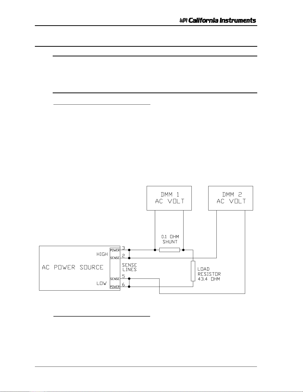
User and Programming Manual - Rev C
6.3.2 Measurement Calibration - Low Scale
Note: Measurement calibration can be done at any output frequency setting
as only one set of calibration coefficients is used for measurement
calibration. However, for best results, calibrate the measurements at
the frequency which is used in most applications, e.g. 50 Hz, 60 Hz, or
400 Hz.
Refer to Table 6-1 for correct load resistors based on model number.
Low Scale Voltage Measurement Calibration
1. Connect the test equipment to the power source as shown in Figure 6-2. Do not connect
any load during this step. Voltage calibration must be done under no load conditions.
2. Select the Low Voltage Range and program the output voltage to 10 volt AC.
3. Put the Power Source in CAL mode by pressing the recessed CAL button.
4. Use the SELECT key to select the Voltage Measurement calibration mode. This mode is
indicated by the FREQ LED.
5. Use the left control knob to adjust the voltage reading shown on the right hand LCD until
it reads as close as possible to the reference reading as displayed on the external DMM.
Figure 6-2: Test Equipment Hook-up for Current and Power Measurement Calibration
Low Scale Current Measurement Calibration
1. Connect the test equipment to the power source as shown in Figure 6-1.
2. Do not apply a load to the output terminals. Make sure the external DMM used for
voltage measurement is across the same terminals.
46 November 2001 TL Series
Page 56

User and Programming Manual - Rev C
3. The output voltage must be programmed to 10.0 volts.
4. Use the SELECT key to select the Current Measurement calibration mode. This mode is
indicated by the I RMS LED.
5. Use the left control knob to adjust the current reading shown on the right hand LCD until
it reads as close as possible to 0.0. Do not go past a reading of zero.
Low Scale Peak Current Measurement Calibration
1. Connect the test equipment to the power source as shown in Figure 6-1. Do not connect
the load.
2. Program the output voltage to 10.0 volts.
3. Use the SELECT key to select the Peak Current Measurement calibration mode. This
mode is indicated by the I PK LED.
4. Use the left control knob to adjust the peak current reading shown on the right hand LCD
until it reads as close as possible to 0.0. Do not go past a reading of zero.
Low Scale Power Measurement Calibration
1. Connect the test equipment to the power source as shown in Figure 6-1. Do not connect
the load.
2. Program the output voltage to 10.0 volts.
3. Use the SELECT key to select the Power Measurement calibration mode. This mode is
indicated by the PWR LED.
4. Use the left control knob to adjust the power measurement reading shown on the right
hand LCD until it reads as close as possible to 0.0. Do not go past a reading of zero.
Note: The method of adjusting the low scale values for voltage, current and
power insure that the measured value is correct for small values.
Under a no-load condition, however, the measured value may not be 0
TL Series November 2001 47
Page 57

User and Programming Manual - Rev C
6.3.3 Measurement Calibration - Full Scale
Note: Measurement calibration can be done at any output frequency setting
as only one set of calibration coefficients is used for measurement
calibration. However, for best results, calibrate the measurements at
the frequency which is used in most applications, e.g. 50 Hz, 60 Hz.
Refer to Table 6-1 for correct load resistors based on model number.
Full Scale Voltage Measurement Calibration
1. Connect the test equipment to the power source as shown in Figure 6-1. Do not connect
any load during this step. Voltage calibration must be done under no load conditions.
2. Select the High Voltage Range and program the output voltage to 240.0 volts AC or the
maximum voltage available if less than 240 Volts.
3. Put the Power Source in CAL mode by pressing the recessed CAL button.
4. Use the SELECT key to select the Voltage Measurement calibration mode. This mode is
indicated by the FREQ LED.
5. Use the left control knob to adjust the voltage reading shown on the right hand LCD until
it reads as close as possible to the reference reading as displayed on the external DMM.
Full Scale Current Measurement Calibration
1. Connect the test equipment to the power source as shown in Figure 6-2.
2. Apply the 43.4 Ω resistive load to the output terminals. Make sure the external DMM
used for voltage measurement is across the sense terminals.
3. Program the output voltage to a value that produces the maximum output current. Refer
to the following for the maximum current:
POWER SOURCE MAX CURRENT
351TL 2.8 A
251TL 2.4 A
4. Use the SELECT key to select the Current Measurement calibration mode. This mode is
indicated by the I RMS LED.
5. Use the left control knob to adjust the current reading shown on the right hand LCD until
it reads as close as possible to the reference reading indicated by the DMM measuring
the current shunt voltage (DMM 1). Note that .28 V reading represents 2.8 Amps if the
recommended 100 mΩ shunt is used.
Full Scale Peak Current Measurement Calibration
1. Connect the test equipment to the power source as shown in Figure 6-2.
2. Select the low voltage range and program the output voltage to 135 volts. Apply the load
for the maximum current allowed.
3. Use the SELECT key to select the Peak Current Measurement calibration mode. This
mode is indicated by the I PK LED.
48 November 2001 TL Series
Page 58

User and Programming Manual - Rev C
4. Use the left control knob to adjust the peak current reading shown on the right hand LCD
until it reads as close as possible to the reference reading derived from the external
DMM (DMM 1). Remember the peak current value is equal to 1.414 times the value
shown on the external DMM.
Full Scale Power Measurement Calibration
1. Connect the test equipment to the power source as shown in Figure 6-2.
2. Program the output voltage to 135 volts and apply the maximum load.
3. Use the SELECT key to select the Power Measurement calibration mode. This mode is
indicated by the PWR LED.
4. Calculate the power by multiplying the external reference current reading (DMM 1) with
the external reference voltage reading (DMM 2).
5. Use the left control knob to adjust the power measurement reading shown on the right
hand LCD until it reads as close as possible to the calculated power reading.
6.4 Non-Routine Calibration
The following calibrations are not required on a routine basis:
• Current Transformer Adjustment (Section 6.4.1). If either the current or power
measurements cannot be adjusted, this adjustment must be performed.
• Current Limit Adjustment (Section 6.4.2). This calibration is only required if the output
current, while operating in the constant voltage or current mode, is not equal to or more
than the programmed value.
• Open Sense Adjustment (Section 6.4.3). This adjustment must be made if the output
voltage can’t be calibrated while operating in the constant current mode. If the output
faults, with no-load, while operating in the Constant Voltage mode, this adjustment must
also be made.
• Amplifier Offset Adjustment (Section 6.4.4).
All of the non-routine calibration adjustments must be made with the top cover removed.
Refer to
Figure 6-3 for the location of the internal adjustments.
TL Series November 2001 49
Page 59

User and Programming Manual - Rev C
6.4.1 Current Transformer Adjustment
Note: The Current Transformer must be adjusted before the Current Limit
and Current Measurement Adjustments.
1. Connect the test equipment as shown in Figure 6-2. Use the 43.4 ohm load.
2. Program the output voltage to 135V on the low voltage range and 60 Hz.
3. Use the SELECT key to select the Current Measurement display. Note that this is not the
Current Measurement calibration mode. Only the I RMS LED should be illuminated.
4. Observe the actual output current as shown on the external DMM and current shunt.
Adjust R3 on the Range/Relay Board for a measurement display equal to the actual
output current.
CAUTION: The amplifier wind tunnel must be covered for proper cooling if the
adjustment takes more than 1 minute.
6.4.2 Current Limit Adjustment
Note: If the Current Limit and High Current Measurement Range Adjustments
are both adjusted, the High Current Measurement Range must be
adjusted first.
1. Connect the test equipment as shown in Figure 6-2. Use the 43.4 ohm load.
2. Program the current to 2.0 A. Program the output to the low voltage range, 60 Hz.
Adjust the output voltage for an output current of 2.1 amps. If the output faults before
2.1 A is reached, adjust R50 several turns clockwise and readjust the output for 2.1 A.
CAUTION: The amplifier wind tunnel must be covered for proper cooling if the
adjustment takes more than 1 minute.
1. Slowly adjust R50 on the Oscillator Board counterclockwise just until the output faults.
50 November 2001 TL Series
Page 60
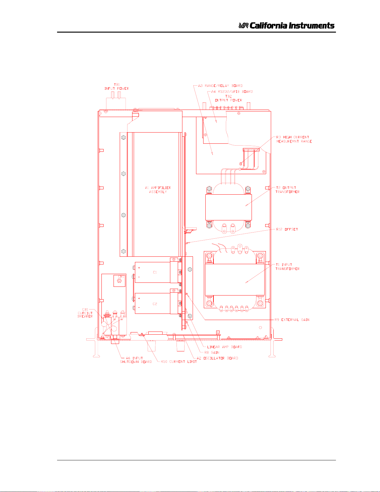
User and Programming Manual - Rev C
Figure 6-3: Internal Adjustments
TL Series November 2001 51
Page 61

User and Programming Manual - Rev C
6.4.3 Open Sense Adjustment
Connect the test equipment as shown in Figure 6-1.
NOTE: The 351TL must be configured for the Constant Current Mode of
operation for this procedure. For this mode jumpers W1 and W2 on the
controller must be removed.
Disconnect the SENSE HIGH terminal on the rear panel terminal strip. Connect the external
AC DMM between the two output POWER terminals on the rear panel.
Program the output to 100.0 volts and adjust R8 on the Amplifier Board for an output voltage
of 115 volts.
Turn off the front panel circuit breaker and reinstall the top cover. Also reconnect the
external SENSE terminals at the rear panel.
Reinstall jumper W1.
6.4.4 Amplifier Offset Adjustment
Turn off the Front Panel circuit breaker.
Connect the DMM to the primary of the output transformer, T2. The transformer primary terminals
are the two wire lugs. Refer to
Figure 6-3. Make sure there is a good electrical connection to T2 by verifying the electrical
resistance with the DMM. The resistance must be less than 1 ohm.
Switch the DMM to the DC mode. Turn on the Front Panel circuit breaker. Adjust the offset
adjustment, R12, for a DC voltage less than 0.0005 volts. Make sure the AC voltage is programmed
to 0.0 volts for this adjustment. Refer to
Figure 6-3 for the location of all adjustments.
52 November 2001 TL Series
Page 62
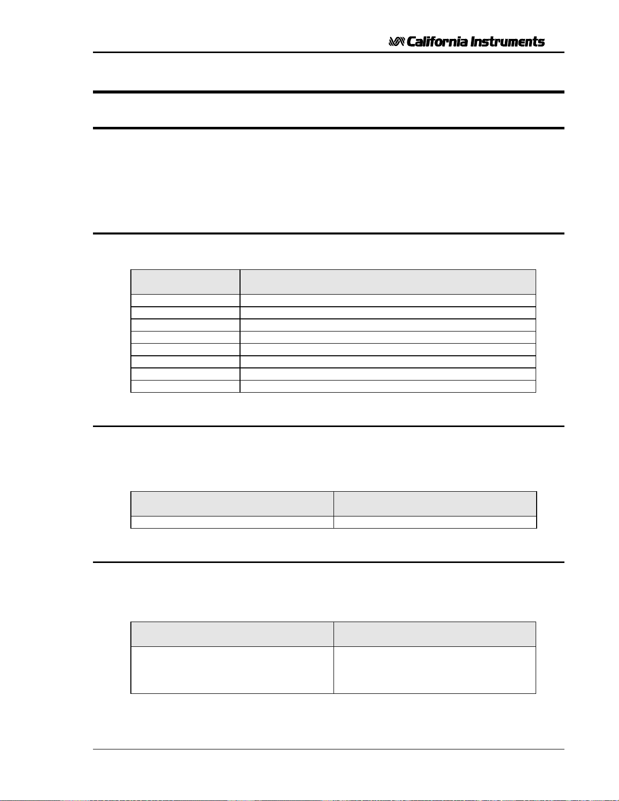
User and Programming Manual - Rev C
7 Service
7.1 General
This section describes suggested maintenance and troubleshooting procedures. The
troubleshooting procedure is divided into two sections. The first section deals with basic
operation and connection of the equipment. The second section requires opening the unit and
using the LED indicators and a simple multimeter to troubleshoot the unit down to the module
level. Only a qualified electronic technician should attempt this level of troubleshooting.
7.2 Basic Operation
PARAGRAPH PROBLEM
7.2.1 Poor Output Voltage Accuracy
7.2.2 Poor Output Voltage Regulation
7.2.3 Distorted Output
7.2.4 Unit Shuts Down After 3-5 Seconds
7.2.5 No Output and no lights on front panel
7.2.6 No output but “Display” on front panel is on
7.2.7 Fault Lamp on
7.2.8 Can’t program AC Power System on GPIB/RS232
Table 7-1: Basic Symptoms
7.2.1 Poor Output Voltage Accuracy
If the power source exhibits poor programmed voltage accuracy, the following item may be at
fault:
Table 7-2: Poor Output Voltage Accuracy
CAUSE SOLUTION
The calibration is incorrect. Calibrate the output.
7.2.2 Poor Output Voltage Regulation
If the AC Power Source exhibits poor voltage regulation the following item may be at fault:
Table 7-3: Poor Output Voltage Regulation
CAUSE SOLUTION
The Remote Sense lines are not
connected at the same point monitored by
the external voltmeter used for load
regulation check.
Connect AC voltmeter to Remote Sense
lines on the Rear Panel Power Output
terminal strip.
TL Series November 2001 53
Page 63
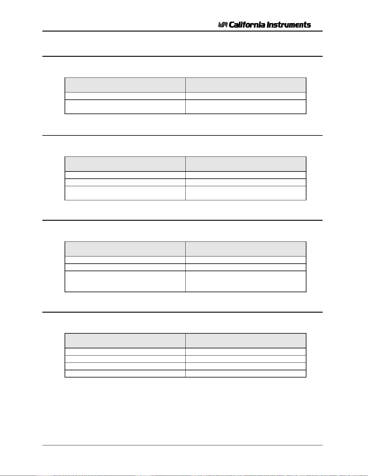
User and Programming Manual - Rev C
7.2.3 Distorted Output
Table 7-4: Distorted Output
CAUSE SOLUTION
Power source is grossly overloaded. Reduce load.
The crest factor of the load exceeds 3:1. Reduce load current peaks by reducing
7.2.4 Unit Shuts Down After 3-5 Seconds
Table 7-5: Unit Shuts Down After 3-5 Seconds
CAUSE SOLUTION
Output shorted. Remove output short.
Output grossly overloaded. Remove overload.
Operating load with too high inrush or start
up currents.
load.
Consult factory for application advice.
7.2.5 No Output and No Lights on Front Panel
Table 7-6: No Output and No Lights on Front Panel
CAUSE SOLUTION
Front panel power switched off. Switch the breaker on.
No input power to the input connector. Ensure correct input power.
Blown fuse. Check fuse F1 and F2 on the DC power
supply and replace with same type and
rating. See Figure 7-2.
7.2.6 No Output but “Display” on Front Panel is On
Table 7-7: No Output But "Display" Is On
CAUSE SOLUTION
“OUTPUT ON” switch is turned off. Turn OUTPUT ON switch to “ON”.
Current limit programmed down or to zero. Program current limit higher.
Voltage programmed down or to zero. Turn amplitude control up.
Fault LED is lit. Cycle Rear Panel power switch off and on.
54 November 2001 TL Series
Page 64
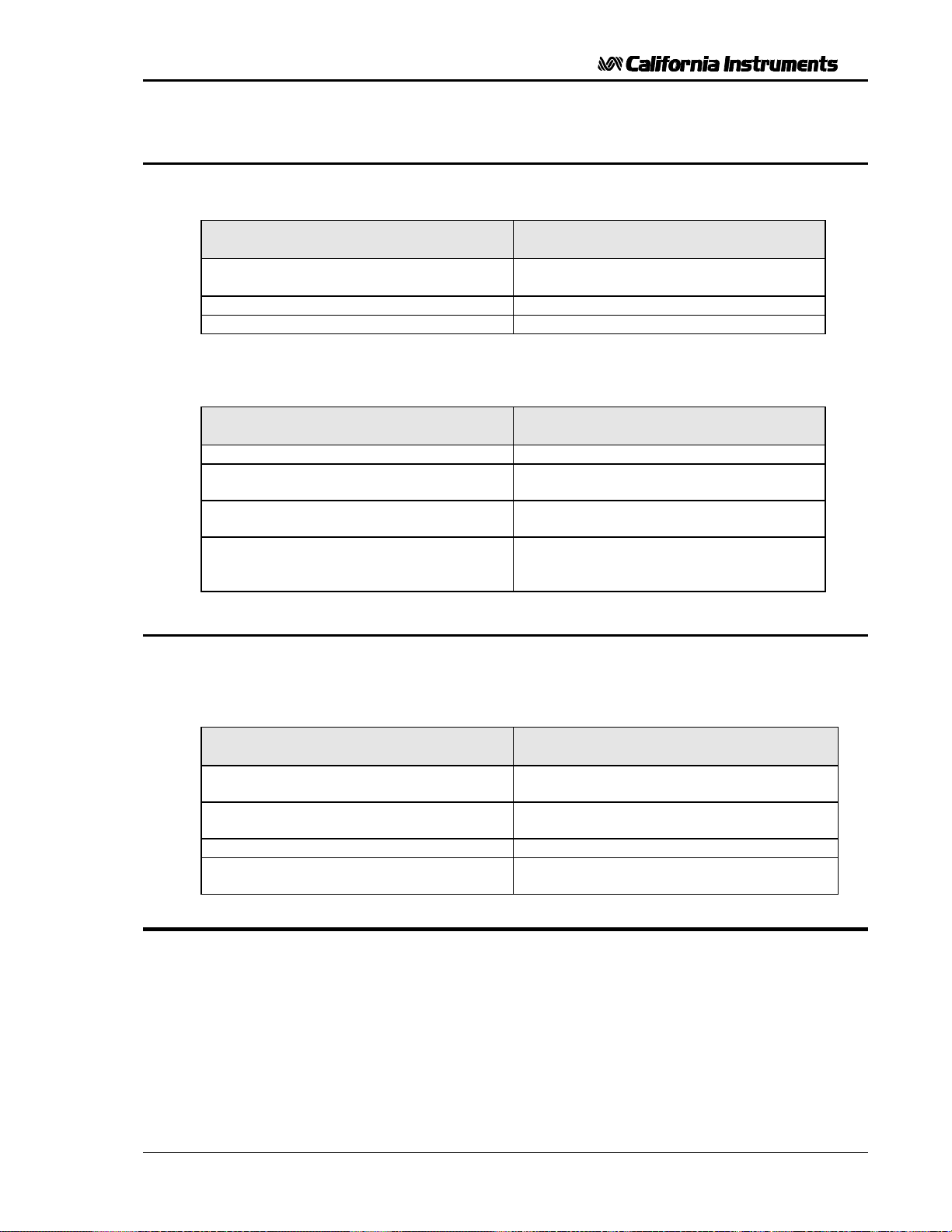
User and Programming Manual - Rev C
7.2.7 Fault Lamp On
If the power source Fault lamp is on, the following may be at fault:
CAUSE SOLUTION
Ambient temperature is too high. Operate power source between 0 and
Fan or ventilation holes are blocked. Remove obstructions.
Fan not working. Replace fan. Consult factory.
If the Power Source is configured to operate in the Constant Voltage mode, the Fault lamp
comes on when the output load current has exceeded the programmed current limit value. If the
AC Power Source Fault lamp is on, the following items may be at fault:
CAUSE SOLUTION
The output is overloaded. Remove the overload.
The programmable current limit level is set
too low for the load being driven.
The programmable current limit is
incorrectly calibrated.
The Remote Sense lines are not
connected.
50°C.
Compute and reprogram the correct
programmable current limit level.
Perform the calibration in Section 6.4.2
On the Rear Panel Power Output terminal
block, connect terminal 2 to 3. Also
connect terminal 5 to 6.
7.2.8 Can’t Program AC Power System on GPIB or RS232
If the power source does not respond to IEEE-488 GPIB or RS232 programming, the following
items may be at fault:
CAUSE SOLUTION
The power source unit address is
incorrect.
GPIB or RS232 cable is loose at power
source rear panel.
RS232/GPIB Assembly has failed. Replace the RS232/GPIB Assembly.
Power connection to RS232/GPIB Assy
is bad.
Update address. See section 8.3.
Check connection, tighten jackscrews.
Remove top cover. Connect power to
RS232/GPIB Board, J1. Refer to Figure 7-1.
7.3 Module Removal
Figure 7-1 shows the location of the internal modules and assemblies. The figure shows the
Amplifier Module, A7, with the insulator removed.
TL Series November 2001 55
Page 65
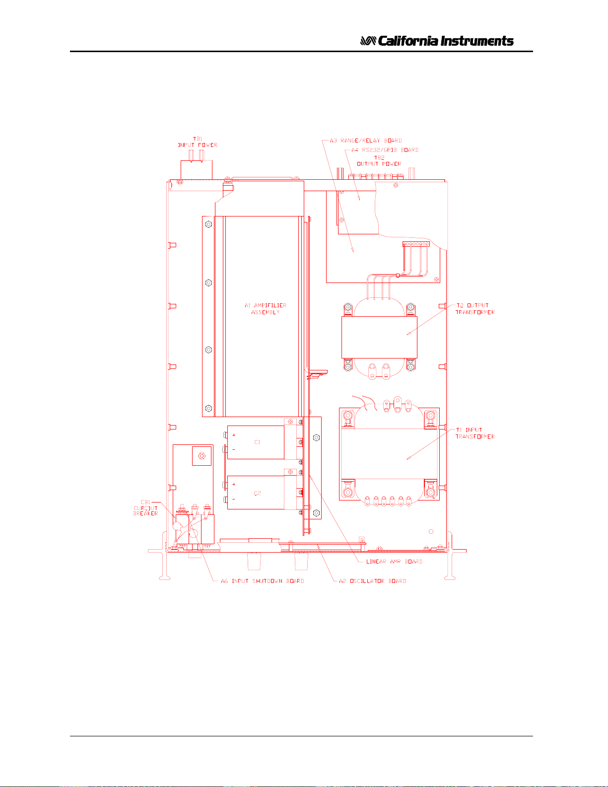
User and Programming Manual - Rev C
Figure 7-1: Assembly Location
56 November 2001 TL Series
Page 66
User and Programming Manual - Rev C
3 4 5
7.3.1 Oscillator Module Removal/Replacement
If a fault is found that requires the replacement of the Oscillator Module (Assembly A1) follow the
following steps and refer to
Figure 7-1 for the module locations:
1. Turn off the front panel circuit breaker. Remove the input power from the rear panel terminal
block.
2. Remove the top cover.
3. Remove the front panel knobs.
4. Remove 5 screws that hold the oscillator assembly to the front panel. The oscillator
assembly can now be removed.
7.3.2 Amplifier Removal/Replacement
If a fault has been found that indicates the failure of the amplifier module (Assembly A7), check
the condition of the +300 VDC fuse (F2) before replacing the amplifier. Refer to
Figure 7-1 for the location of the fuse.
If it is determined that the amplifier module must be replaced, perform the following procedure:
1. Turn off the input circuit breaker.
2. Disconnect AC input power at the rear panel.
Remove the AC Power Source top cover by removing (13) #6-32 x 5/16” FLH
screws.
Remove the (2) #6-32 x 1” screws and lock washers that hold the amplifier module
along the left chassis side panel.
Remove (2) #6-32 x 3/8” screws and lock washers located near the connector,
attaching the red insulator to the center bracket.
6. Remove the amplifier by pulling it away from the connectors and lifting it up and out of
the amplifier cage.
7. The amplifier may be replaced by following this procedure in reverse order.
8. Check the amplifier 20 A fuse (F2) located on the DC Supply Board, A6, and
replace it if necessary.
9. After an amplifier has been replaced, readjust its gain.
TL Series November 2001 57
Page 67
User and Programming Manual - Rev C
7.4 Replaceable Parts
In order to ensure prompt, accurate service, please provide the following information, when
applicable for each replacement part ordered.
a. Model number and serial number of the instrument.
b. California Instruments’ part number for the sub-assembly where the component is located.
(California Instruments PART #)
c. Component reference designator. (SEQ #)
d. Component description.
e. Component manufacturers' FSCM number. (VENDOR)
All replaceable part orders should be addressed to:
California Instruments Corporation.
Attention: Customer Service
9689 Towne Centre Drive
San Diego, California 92121-1964
United States of America
Orders may also be placed using the following fax number: 1 858 677 0904
SEQ # C.I. PART # DESCRIPTION VENDOR QTY
A1 4005-714-1 PC Assy, Oscillator 16067 1
A2 4005-715-1 PC Assy, Range/Relay 16067 1
A3 4005-702-2 PC Assy, RS232/GPIB 16067 1
A4 4005-716-1 PC Assy, Motherboard 16067 1
A6 4005-713-1 PC Assy, DC Supply 16067 1
A7 4009-456-3 PC Assy, Heatsink, SW Amp 16067 1
A9 4005-710-1 PC Assy, EMI Filter 16067 1
B1 241180 Fan, 4, 48 VDC 23936 1
F1 270064 Fuse, 1/2A, 250V (slo-blo) 71400 1
F2 270176 Fuse, 20A, 250V 71400 1
Table 7-8: Replaceable Parts
58 November 2001 TL Series
Page 68

User and Programming Manual - Rev C
8 Remote Control
8.1 Introduction
The TL Series can be furnished with a combination IEEE-488 and RS232C control interface at
the time of purchase. This interface is part of the -OP1 option package. This interface option
also includes the California Instruments Graphical User Interface program - PGUI32. This
Windows™ program provides a soft front panel to the instrument when connected to a PC
through the RS232C or IEEE-488 interface. Additional benefits are obtained from using the PC
as a control interface. Some of these benefits include the ability to store measurement data to
disk and produce output transients to simulate commonly occurring AC line conditions.
The PGUI32 is a Windows™ program and as such requires a PC capable of running
Windows 95/98™, Windows ME™, or Windows NT/2000. For best performance, a Pentium
based PC is recommended. Intel™ 80486 based PC's will exhibit poor performance while
generating transients due to their lack of processing speed.
Complete information on how to use the PGUI32 can be found in the on-line help supplied with
the program. Use the Help menu or press on any of the many Help keys located in all program
windows for an explanation of the relevant screen or function.
As always, California Instruments appreciates your patronage and would welcome any
comments and suggestions you might have regarding this software or any of its other products.
Use the End-user feedback form located on page Error! Bookmark not defined.. The same
form can be used to report software bugs should you encounter any.
8.2 PGUI32 Program Requirements
To successfully install and operate the PGUI32 program, you will need the following equipment:
California Instruments AC power source. Supported models are :
• 251TL / 351TL
• 1001P
• 1251P
• 801RP
• 1251RP
• 2001RP / 2001RP-AV / 2001RP-LZ
PC capable of running Windows 95™, Windows 98™, Windows ME or Windows NT/2000
• RS232C communications port
• RS232C serial cable (supplied with the -OP1 option package.) See next section for
RS232C cable wiring
or
• National Instruments IEEE-488 Controller Card
TL Series November 2001 59
Page 69
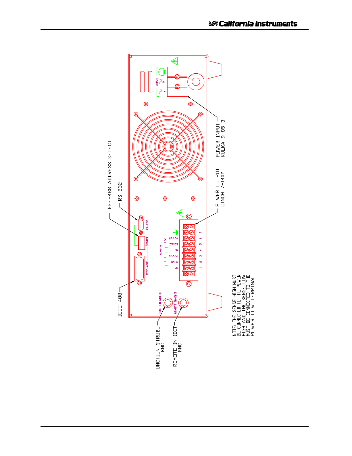
User and Programming Manual - Rev C
Figure 8-1: Rear Panel View
60 November 2001 TL Series
Page 70
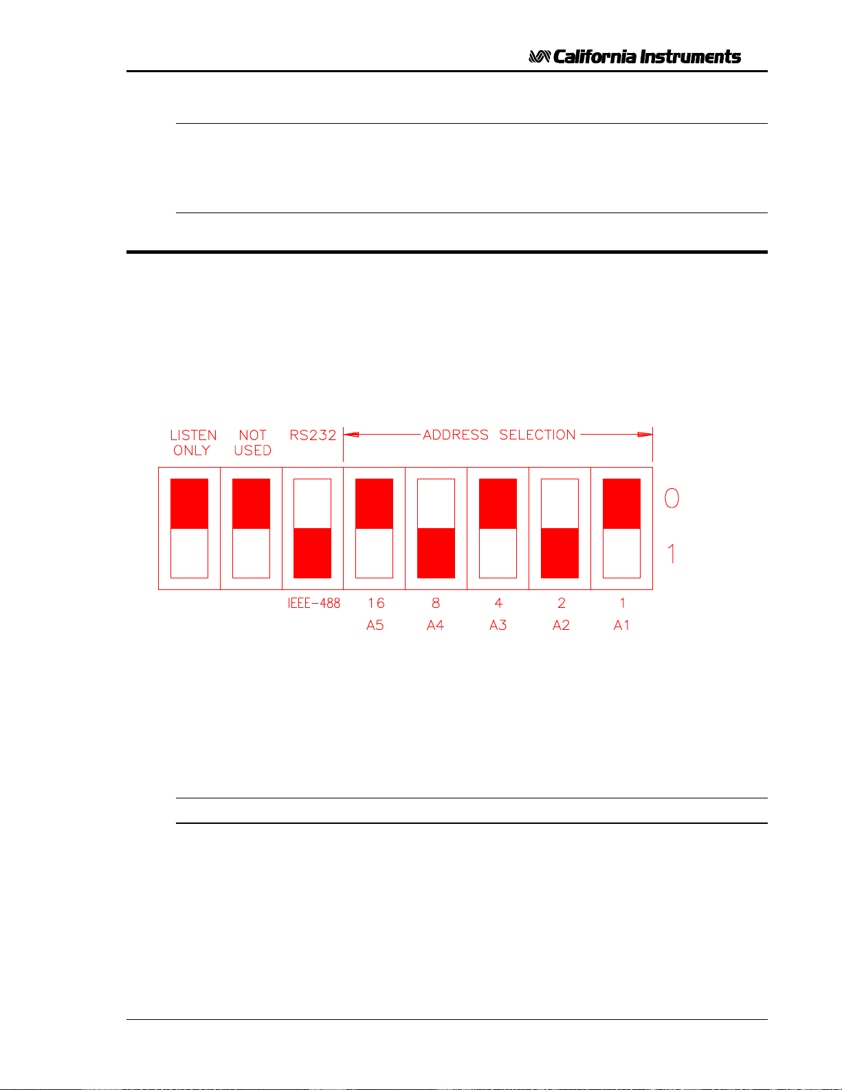
User and Programming Manual - Rev C
Note: The PGUI32 can be run in the absence of a power source. If no AC source is
available, the PGUI32 can be operated in a simulation mode. The program will
detect these conditions and start up in simulation mode after notifying the
operator. Measurements in this case will be simulated and should not be used for
any analytical purpose.
8.3 IEEE Interface
The 251 / 351TL can optionally be equipped with both RS232C and IEEE-488 interfaces. The
desired interface is selected by moving the dip switch position 5 to the correct mode. Only one
interface can be active at a time. Refer to Figure 8-1 for the location of this switch.
The IEEE address of the 251 / 351TL is set using the dipswitch at the rear of the unit. Switch
position 4 through 0 corresponds to bits 4 through 0 of the IEEE address. See figure below.
Figure 8-2: GPIB Address Selection Switch
• The black section represents the switches.
• The above configuration would cause the 251 / 351TL to be in GPIB mode at address 10.
• Listen only must be in the up position to work properly.
Note: Switch setting changes do not take effect until power is cycled.
TL Series November 2001 61
Page 71

User and Programming Manual - Rev C
8.4 RS232C Interface
A suitable cable to connect the 251 / 351TL AC Source to a 9 pin PC-AT style serial port is
supplied with the source. If you are unable to locate this cable, you need to use a cable that
conforms to the wiring diagram shown in Figure 8-3.
Note: This cable is not bi-directional so it is important to mark the PC side and the AC
source side of this cable. If the cable is connected in reverse, it will not operate
correctly.
The TL Series expects a LF (Hex 10) terminator at the end of each string sent over the RS232C
interface. If the programming environment you use to develop test programs does not append a
LF terminator to each output string, the TL Series will not respond. This is true of programs like
LabView™ using VISA drivers.
8.4.1 Serial Communication Test Program
The following sample program written in Quick-BASIC can be used to check communication to
the TL Series AC source over the RS232C serial interface. The interface is optional and must be
installed for this to work.
'California Instruments 251/351TL RS232C Communication Demo Program
'(c) 1998 Copyright California Instruments, All Rights Reserved
'
'This program is for demonstration purposes only and is not to be
'used for any commercial application
'================================================================
'Function and Subroutine Declarations
DECLARE FUNCTION retstring$ ()
'================================================================
'MAIN PROGRAM CODE
'================================================================
'OPEN COM2. Replace with COM1, COM3 or COM4 for Com port used
'The input and output buffers are set to 2K each although
'this is not required for most operations.
OPEN "COM2:19200,n,8,1,BIN,LF,TB2048,RB2048" FOR RANDOM AS #1 LEN = 1
CLS
PRINT "**** 251/351TL INTERACTIVE MODE ****"
'Enter and endless loop to accept user entered commands
DO
INPUT "Enter Command ('quit' to exit)--> ", cmd$
IF cmd$ <> "QUIT" AND cmd$ <> "quit" THEN
IF cmd$ <> "" THEN
PRINT #1, cmd$ + CHR$(10);
END IF
IF INSTR(cmd$, "?") THEN
PRINT "AC Source query response = "; retstring$
END IF
'Check for Errors after each command is issued
PRINT "Sending non-query syntax check *ESR?"
'On fast PC's we may have to hold off between commands
FOR t = 0 TO 1000: NEXT t
PRINT #1, "*ESR?" + CHR$(10);
esr% = 0 'Clear last error
'Mask off bits 5,4,3,2 only. Other bits are not used.
esr% = VAL(retstring$) AND 60
'Process esr% value for error bits
IF esr% AND 4 THEN
PRINT "*** Query Error Reported by AC Source ***"
62 November 2001 TL Series
Page 72

User and Programming Manual - Rev C
END IF
IF esr% AND 8 THEN
PRINT "*** Instrument Dependent Error Reported by AC Source ***"
END IF
IF esr% AND 16 THEN
PRINT "*** Command Execution Error Reported by AC Source ***"
END IF
IF esr% AND 32 THEN
PRINT "*** Command Syntax Error Reported by AC Source ***"
END IF
'Clear ERR. -XXX Message from front panel if any error occured
IF esr% <> 0 THEN
PRINT #1, "*CLS" + CHR$(10);
END IF
END IF
LOOP UNTIL cmd$ = "QUIT" OR cmd$ = "quit"
'Close COM port on exit
CLOSE #1
END
'================================================================
FUNCTION retstring$
'This function returns a response string from the P/RP/TL Series
'AC power source. The QBasic statement LINE INPUT cannot be used
'as the P/RP/TL Series does not return a CR <13> after a response
'message. The LINE INPUT function waits for a CR before
'returning a string. The P Series returns a LF <10> instead
'so we need to poll each returned character for a LF to
'assemble the response string. The COM port needs to be
'opened AS random with a record length of 1 for it to support
'this function. Also, the device number is assumed to be #1
'Optionally, this value could be passed as a parameter to
'make this program more generic.
DIM char AS STRING * 1
DIM resp AS STRING
char = ""
resp = ""
DO
char = INPUT$(1, #1)
resp = resp + char
LOOP UNTIL char = CHR$(10)
'Return result
retstring = LEFT$(resp, LEN(resp) - 1)
END FUNCTION
TL Series November 2001 63
Page 73
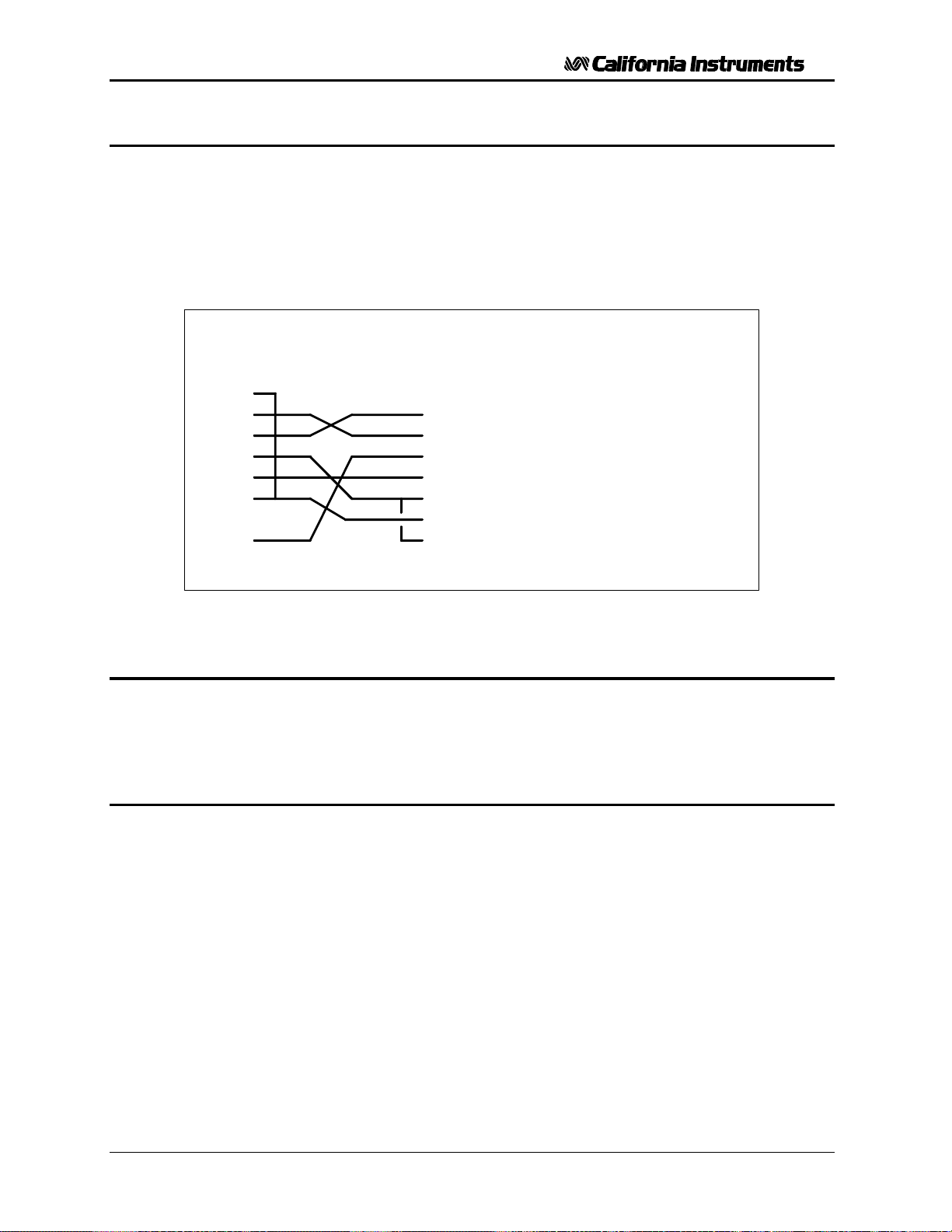
User and Programming Manual - Rev C
8.4.2 Serial Cable Diagram
California Instruments AC power sources require a special RS232C cable to communicate with a
PC. Standard null-modem cables obtained from a computer hardware store most likely will not
work. For this reason, all California Instruments power sources that operate over RS232C are
supplied with a RS232C 9 pin female to 9 pin female cable.
If for some reason this cable cannot be located, the following cable diagram shown in Figure 8-3
should be used when constructing a serial cable.
DB-9 PC
Pin
1
2
3
4
5
6
7
8
9
Figure 8-3: RS232C Interface Cable Wiring Diagram
8.5 PGUI32 Setup and Installation
This section covers installation of the PGUI32 from the distribution disk to the user’s PC. Make
sure the PC is capable of running Windows with at least 16 Mbytes of memory and 4 Mbytes of
available hard disk space.
DB-9 AC Source
Pin
Direction
1
output
2
input
3
output
4
output
5
-
6
input
7
-
8
-
9
output
Description
reserved
Receive data(RxD)
Transmit data (TxD)
Data Terminal Ready (DTR)
Signal Ground
Data Set Ready (DSR)
no connect
no connect
reserved
8.5.1 Connecting the AC Source to the PC When Using RS232
Connect the AC source to the PC using an RS232C cable.
The AC source com port settings are set as follows:
Baud rate: 19200 baud for model 251 / 351TL
Data bits: 8
Stop bits 1
Parity bits: none
Handshake: Hardware
The AC source is configured to accept the above setting.
Select the RS232 interface by sliding the interface selection dipswitch on the rear panel to the
RS232 position.
64 November 2001 TL Series
Page 74

User and Programming Manual - Rev C
8.5.2 Connecting the AC Source to the PC Using IEEE-488
Connect the AC source to the PC using an IEEE-488 interface cable. A National Instruments
GPIB controller card is required to use the PGUI32 program.
Select the IEEE-488 interface by sliding the interface selection dip switch on the rear panel to the
IEEE-488 position.
Set the desired IEEE address using DIP switch position 4 through 0 on the rear panel.
8.5.3 Installing the PGUI32 Software
The PGUI32 software is distributed on a CD-ROM. The PGUI32 must be installed from the CD
using the setup program as all required files are compressed. You cannot copy the contents of
the CD to your PC hard drive and run the program. To install the PGUI32, proceed as follows:
1. Turn on the PC and boot up in Windows™
2. Insert the CD in your CD-ROM drive.
3. From the Windows Start Menu, select RUN.
4. At the “Open” prompt, type D:Setup depending on which disk drive you used and
click on the OK button.
5. Select the 251TL/351TL entry under low Power AC Sources from the list of model
numbers.
6. Select the GUI Software tab and click on the "Execute Selection" button.
7. Follow the instructions provided by the setup program to complete the installation.
8. When the installation has completed, remove the CD from the drive and store it in
a safe place.
Reboot the PC to activate the new settings. You are now ready to start using the PGUI32
software.
TL Series November 2001 65
Page 75

User and Programming Manual - Rev C
8.6 Trouble Shooting - RS232C
This section provides guidelines for resolving communication problems that may occur when
using the PGUI32 software under Windows.
You may encounter problems when using the serial interface with the PGUI32 program that is
supplied with the interface option for this source.
Symptoms:
1. Unable to verify connection to the power source through RS232C interface. Time-out occurs
and dialog box appears that asks if you want to switch to simulation mode. An error message
(ERR -100) may appear on the front panel LCD’s of the power source.
- Or -
2. Verification is successful but slewing of voltage, frequency or current limit results in an ERR -
100.
Things to check first:
1. Is the PC com port you selected to use really available for this purpose? On older PC’s com
port interrupts are often shared between com 1 and com3 as well as com2 and com 4. If any
of these other com ports is in use, it may prevent you from using the com port that shares
the same interrupt.
2. Did you use the RS232C cable that was supplied with the P/RP AC source? This is not a
null-modem cable and cannot easily be obtained at a computer store. If you do not have the
original cable, consult the PGUI32 on line help under Interface settings for a wiring diagram.
3. Did you connect the cable in the right direction? This cable is uni-directional and should be
marked with a SOURCE and a PC label. Make sure you connect the SOURCE side of the
cable to the back of the AC source and the PC side of the cable to the PC port.
Resolution for Symptom 1
The P and RP Series of AC sources require hardware handshaking to control data flow from the
PC to the AC source. After receiving a command, the AC source asserts the DTR line to hold off
further communication from the PC until the command just sent has been processed. Under
Windows 95, it is possible to use a 16 byte transmit buffer if a 16550 UART is present. This FIFO
exceeds the length of most AC source commands. When enabled, this mode may result in more
than one command being placed in the UART output buffer. If this happens, the handshake from
the AC source will not prevent the content of this buffer being sent to the AC source and thus will
result in more than one command being sent to the AC source.
To resolve this problem, the UART FIFO length needs to be reduced or disabled altogether. The
procedure to disabled the FIFO mode is outlined in the next paragraph.
Note: If turning off the UART FIFO conflicts with other applications that need to run on the same
PC using the same COM port, this solution may not be acceptable. In this case, skip this step
and proceed to the second symptom resolution which relies on a software implemented hold-off
instead of turning off the FIFO buffer. If you are using Windows 3.1 and experience the same
problem, the latter method is the only resolution available to you so you should skip the next
paragraph as well.
66 November 2001 TL Series
Page 76
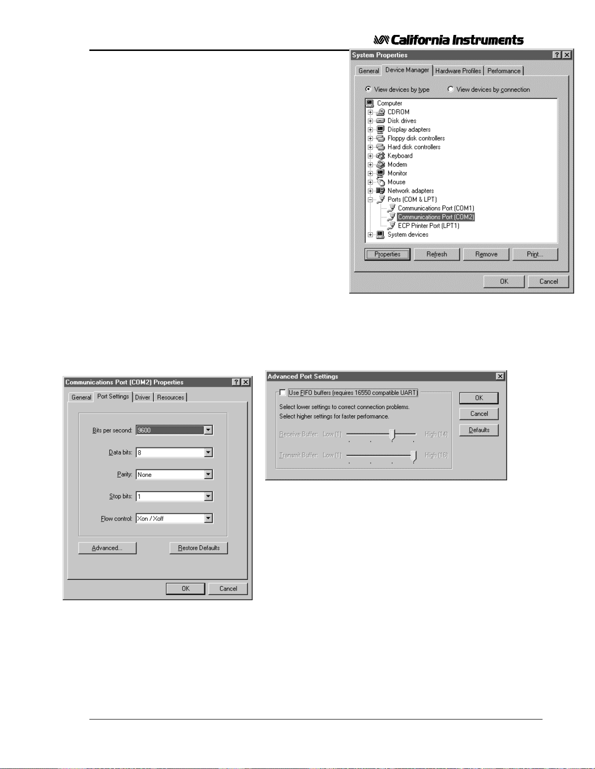
User and Programming Manual - Rev C
Procedure
1. Make sure the PGUI32 program is closed and no
device is using the com port in use.
2. From the Windows desktop, right click on the “My
Computer” icon which is located in the top left corner
of the screen.
3. From the popup menu, select the “Properties” entry.
4. This brings up the System Properties dialog box
5. From the tabs shown at the top of the dialog box,
select the “Device Manager” tab.
6. The relevant screen is shown in Figure 8-4.
7. Expand the Ports(COM&LPT) tree selection by
clicking on the ‘+’ sign
8. Select the COM port you plan to use to communicate
with the P or RP series power source.
9. With the correct COM port selected, click on the
Properties button at the bottom left of the dialog box.
10. This brings up the settings dialog box for the COM
port. In this example, COM2 is used.
11. From the tabs at the top of the dialog box, select the “Port
Settings” tab.
12. This should bring up the dialog shown in Figure 8-6.
13. Next, select the Advanced button to bring up the advanced port settings dialog box shown in Figure
8-5.
Figure 8-5: Advanced Port Settings Dialog Box
14. At the top of the dialog box, disable the “Use FIFO buffers
(requires 16550 compatible UART)” checkbox. This will bypass
the UART FIFO’s and enable the hardware handshake to work
correctly.
Figure 8-4: System Properties Dialog Box
15. Click on the all OK buttons to close all dialog boxes that remain
open.
Figure 8-6: COM Port Properties Dialog Box
TL Series November 2001 67
16. This should enable the PGUI32 to work correctly.
Page 77

User and Programming Manual - Rev C
Resolution for Symptom 2
Execute the suggested procedure to resolve symptom 1 first. If an occasional error continues to
occur while slewing the voltage or frequency slider controls in the PGUI32 program, add a
command delay to the PGUI32 Registry Interface section using the following procedure. This
symptom may occur on some PC’s.
The command delay holdoff value is shown in the Interface screen. Edit it's value by overwriting
the value shown.
Higher values than 40 may be set for the CmdDelay parameter if this fix does not resolve your
problem.
68 November 2001 TL Series
Page 78
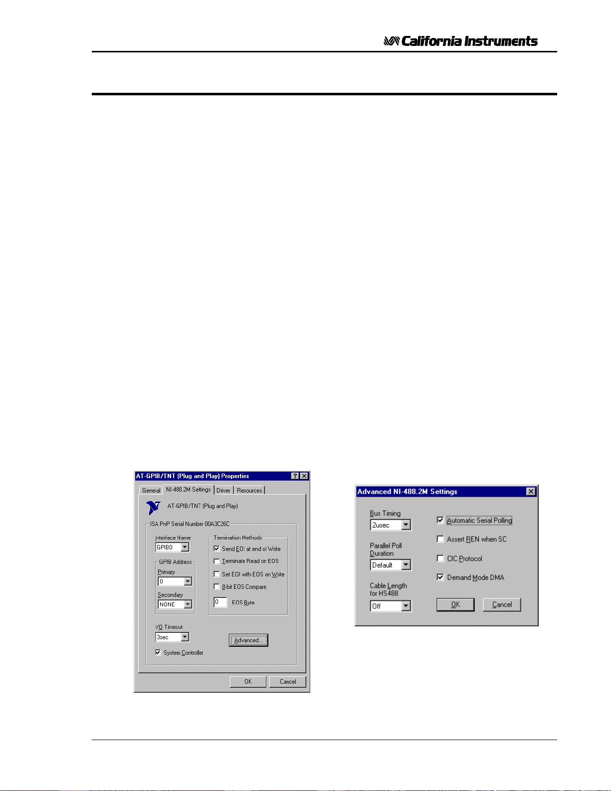
User and Programming Manual - Rev C
8.7 Trouble Shooting - IEEE-488 / GPIB
This section provides guidelines for resolving communication problems that may occur when
using the Power Source with or without the PGUI32 software with a IEEE-488 / GPIB interface.
Symptoms:
1. Unable to verify connection to the power source through IEEE-488 interface. Time-out
occurs any time an attempt is made to verify connection.
Things to check first:
1. Is the Power Source interface option set to use the IEEE-488 interface instead of the
RS232C interface? The DIP switch on the rear panel is used to select the desired interface
mode. Refer to section 8.3.
2. Does the bus address selected in the System, Interface dialog match the address set using
the DIP switches on the Power Source? The GPIB address selected must match the
settings on the DIP switch. If changes are made to the DIP switch setting, the Power Source
power must be cycled off and on to have the new settings take effect.
3. Did you connect the cable in correctly and are both ends of the GPIB cable securely tied
down?
Resolution for Symptom 1
When using a fast IEEE-488 bus controller, the Power Source's IEEE-488 interface may not
handshake fast enough to satisfy the controllers timing requirement. If this is the case, a time-out
will result any time a command is sent to the power source. To rectify this situation, the IEEE-488
controller must be set to use delayed bus timing. For National Instruments GPIB controller cards
running under Windows™, this can be done from the device manager.
Select the GPIB interface and click on the NI-488.2M Settings tab. An Advanced button at the
bottom of the screen will provide access to the Bus Timing parameter. Set this value to 2µsec to
operate with the 251 / 351TL GPIB interface.
Figure 8-8: NI AT-GPIB/TNT Advanced
Settings Dialog
Figure 8-7: NI AT-GPIB/TNT Settings
TL Series November 2001 69
Page 79
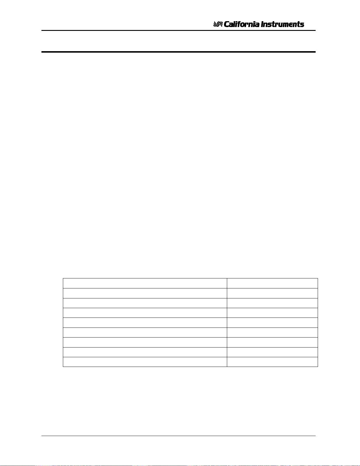
User and Programming Manual - Rev C
8.8 PGUI32 Distribution Files
The installation program will install the following files in the directories specified. Note that files
with the same name that already exists in these directories will not be overwritten as part of the
installation process. If older files of the same name are found, they will be replaced. If you need
to retain a copy of these older version files, we recommend you back these files up prior to
running the installation program.
Application directory files
The following files are copied to the application directory. The application directory name is
chosen by the user during the installation process. The default directory for the PGUI32 is:
C:\Program Files\California Instruments\PGUI32
Pgui32.exe Executable
Pgui32.hlp On Line Help file
Pgui32.cnt Help Contents file
Windows System directory files
The following shared files are stored in the Windows\System directory during installation:
Mscomm32.ocx Microsoft Serial communications active control
ss32x25.ocx Grid spreadsheet active control
Comdlg32.ocx Microsoft Common dialog active control
Comctl32.ocx Microsoft Common controls
Msvbvm60.dll Microsoft Visual Basic 6.0 virtual machine library
Mfc42.dll Microsoft Foundation Classes
Msvcrt.dll Microsoft Visual C++ run-time library
Oleaut32.dll Microsoft OLE automation server
IEC Test Programs Directory Files
File name Description
Generic IEC 1000-4-11 Voltage Variations Test.411_Vars Test levels for IEC 1000-4-11
Generic IEC 1000-4-11 Voltage Dips Test.411_Dips Test levels for IEC 1000-4-11
EN 61326-1 Voltage Interrupts.411_Dips Test levels for IEC 1000-4-11
Generic IEC 1000-4-14 Test Level 1.414_Fluc Test levels for IEC 1000-4-14
Generic IEC 1000-4-14 Test Level 2.414_Fluc Test levels for IEC 1000-4-14
Generic IEC 1000-4-28 Freq Vars Test Level 1.428_Vars Test levels for IEC 1000-4-28
Generic IEC 1000-4-28 Freq Vars Test Level 2.428_Vars Test levels for IEC 1000-4-28
Generic IEC 1000-4-28 Freq Vars Test Level 3.428_Vars Test levels for IEC 1000-4-28
User files for above tests may be distributed as well. These files use a 4XX_USER extension.
70 November 2001 TL Series
Page 80
User and Programming Manual - Rev C
Test Sequence Program Directory Files
File name Description
Sample sequence test file.SEQ Sample output sequence file
Note: The location of these files as well as the files themselves may change with future versions
of the PGUI32. Consult the included readme file for last minute program information.
8.9 Software Registration
Updates of this and other California Instruments programs are posted on a regular basis on the
California Instruments web site. You can find available programs by selecting the Software, GUI's
and Drivers menu. To gain access to these downloads, you will need to register as a user on our
web site. Instructions on how to register and request the required access level for software
downloads, visit our web site at
www.calinst.com
TL Series November 2001 71
Page 81

User and Programming Manual - Rev C
Page intentionally left blank
72 November 2001 TL Series
Page 82

User and Programming Manual - Rev C
9 Introduction to SCPI
SCPI (Standard Commands for Programmable Instruments) is a programming language for
controlling instrument functions over the RS232 or IEEE 488 bus. The same SCPI commands
and parameters control the same functions in different classes of instruments. For example, you
would use the same MEAS:VOLT? command to measure the AC source output voltage or the
output voltage of a SCPI-compatible Multimeter.
9.1 Conventions Used in This Manual
Angle brackets<> Items within angle brackets are parameter abbreviations. For example,
<NR1> indicates a specific form of numerical data.
Vertical bar Vertical bars separate alternative parameters. For example, 0 | 1
indicates that either "0" or "1" can be used as a parameter.
Square Brackets[] Items within square brackets are optional. The representation
[SOURce:]VOLT means that SOURce: may be omitted.
Boldface font Boldface font is used to emphasize syntax in command definitions.
CURR <NRf> shows a command definition.
Upper case font Upper case font is used to show program lines in text. OUTP 1 shows a
program line.
9.2 The SCPI Commands and Messages
This paragraph explains the syntax difference between SCPI Commands and SCPI messages.
The AC source supports two types of commands, IEEE-488-2 common and SCPI subsystem
commands.
• IEEE-488-2 common commands are generally not related to specific operations but to
controlling overall AC source functions such as reset, status and synchronization. All
common commands consist of a three-letter mnemonic preceded by an asterisk:
*RST *IDN? *SRE 255
• SCPI Subsystem commands perform specific AC source functions. They are organized into
an inverted tree structure with the "root" at the top. Some are single commands while others
are grouped within specific subsystems. You must include the root header in all
commands sent to the AC source.
Refer to appendix A for the AC source SCPI tree structure.
Types of SCPI Messages
There are two types of SCPI messages, program and response.
• A program message consists of one or more properly formatted SCPI commands sent from
the controller to the AC source. The message, which may be sent at any time, requests the
AC source to perform some action.
• A response message consists of data in a specific SCPI format sent from the AC source to
the controller. The AC source sends the message only when commanded by a program
message called a "query."
TL Series November 2001 73
Page 83
User and Programming Manual - Rev C
The SCPI Command Tree
As previously explained, the basic SCPI communication method involves sending one or more
properly formatted commands from the SCPI command tree to the instrument as program
messages. The following figure shows a portion of a subsystem command tree, from which you
access the commands located along the various paths (you can see the complete tree in
appendix A).
Root
[:SOURce] :VOLTage [:LEVel]
:CURRent :RANGe
:SYSTem :REMote
:ERRor
:LIMit :FREQuency :LOW?
:HIGH?
Figure 9-1: Partial Command Tree
The Root Level
Note the location of the ROOT node at the top of the tree. Commands at the root level are at the
top level of the command tree. The SCPI interface is at this location when:
• the AC source is powered on
• a device clear (DCL) is sent to the AC source
• the SCPI interface encounters a message terminator
• the SCPI interface encounters a root specifier
Active Header Path
In order to properly traverse the command tree, you must understand the concept of the active
header path. When the AC source is turned on (or under any of the other conditions listed
above), the active path is at the root. That means the SCPI interface is ready to accept any
command at the root level, such as SOURCe or MEASurement.
If you enter SOURCe the active header path moves one colon to the right. The interface is now
ready to accept :VOLTage :FREQuency, or :CURRent as the next header. You must include the
colon, because it is required between headers.
If you now enter :VOLTage, the active path again moves one colon to the right. The interface is
now ready to accept either :RANGe or :LEVel as the next header.
If you now enter :RANGe you have reached the end of the command string. The active header
path remains at :RANGe If you wished, you could have entered :RANGe 150 ;LEVel 115 and it
would be accepted as a compound message consisting of:
1. SOUR:VOLT:RANG 150.
74 November 2001 TL Series
Page 84

User and Programming Manual - Rev C
2. SOUR:VOLT:LEV 115.
The entire message would be:
SOUR:VOLT:RANG 150;LEV 115.
The message terminator after LEVel 115 returns the path to the root.
Note: The TL Series interface buffer is limited to 21 characters, however. As such, compound
commands are not recommended as they often exceed this message length limit.
Moving Among Subsystems
In order to combine commands from different subsystems, you need to be able to restore the
active path to the root. You do this with the root specifier (:). For example, you could set the
output frequency to 60 Hz and set the display mode to frequency.
FREQ 60
DISP:MODE 0
Because the root specifier resets the command parser to the root, you can use the root specifier
and do the same thing in one message:
FREQ 60;:DISP:MODE 0
Including Common Commands
You can combine common commands with system commands in the same message. Treat the
common command as a message unit by separating it with a semicolon (the message unit
separator). Common commands do not affect the active header path; you may insert them
anywhere in the message.
VOLTage 115;*ESE 255
OUTPut 0;*RCL 2
TL Series November 2001 75
Page 85
User and Programming Manual - Rev C
9.3 Using Queries
Observe the following precautions with queries:
• Set up the proper number of variables for the returned data.
• Read back all the results of a query before sending another command to the AC source.
Otherwise a Query Error will occur and the non-returned data will be lost.
9.4 Structure of a SCPI Message
SCPI messages consist of one or more message units ending in a message terminator. The
terminator is not part of the syntax, but implicit in the way your programming language indicates
the end of a line (such as a newline or end-of-line character).
The Message Unit
The simplest SCPI command is a single message unit consisting of a command header (or
keyword) followed by a message terminator.
FREQuency?<newline>
VOLTage?<newline>
The message unit may include a parameter after the header. The parameter usually is numeric:
VOLTage 20<newline>
OUTPut 1<newline>
Combining Message Units
The following command message is briefly described here, with details in subsequent
paragraphs.
Data Query Indicator
Message Unit
Header
SOUR:VOLT 80; FREQ 60; :CURR? <NL>
Header Message Root Message
Separator Unit Specifier Terminator
Separator
Figure 9-2: Command Message Structure
The basic parts of the above message are:
76 November 2001 TL Series
Page 86

User and Programming Manual - Rev C
Message Component Example
Headers SOURC VOLT FREQ CURR
Header Separator The colon in SOUR:VOLT
Data 80 60
Data Separator The space in VOLT 80 and FREQ 60
Message Units VOLT 80 FREQ 60 CURR?
Message Unit Separator The semicolons in VOLT 80; and FREQ 60;
Root Specifier The colon in :CURR?
Query Indicator The question mark in CURR?
Message Terminator The <NL> (newline) indicator. Terminators are not part of the
Note: The use of compound messages such as the one shown in Figure 12-2 is
not recommended as they typically exceed the available receive buffer
length of the TL/RP Series interface.
Headers
Headers are instructions recognized by the AC source. Headers (which are sometimes known as
"keywords") may be either in the long form or the short form.
Long Form The header is completely spelled out, such as VOLTAGE, SYSTEM, and
OUTPUT.
Short Form The header has only the first three or four letters, such as VOLT, SYST, and
OUTP.
SCPI syntax
The SCPI interface is not sensitive to case. It will recognize any case mixture, such as
VOLTAGE, VOLTage or Voltage. Short form headers result in faster program execution.
Note: In view of the 21 character receive buffer size of the TL/RP Series, the
short form is recommended under all circumstances.
Header Convention
In the command descriptions in chapter 10 of this manual, headers are emphasized with
boldface type. The proper short form is shown in upper-case letters, such as DELay.
Header Separator
If a command has more than one header, you must separate them with a colon (SYSTem:ERRor
LIMit:FREQuency:LOW).
Optional Headers
The use of some headers is optional. Optional headers are shown in brackets, such as
VOLTage[:LEVel] 100.
TL Series November 2001 77
Page 87

User and Programming Manual - Rev C
Query Indicator
Following a header with a question mark turns it into a query (VOLTage?, VRANGe?).
Message Unit Separator
When two or more message units are combined into a compound message, separate the units
with a semicolon (VOLT 100;FREQ 60).
Root Specifier
When it precedes the first header of a message unit, the colon becomes the root specifier. It tells
the command parser that this is the root or the top node of the command tree. Note the
difference between root specifiers and header separators in the following examples:
SOURce:VOLTage:LEVel 100 All colons are header separators
:SOURce:VOLTage:LEVel 100 Only the first colon is a root specifier
SOURce:VOLTage:LEVel 100;:FREQuency 55 Only the third colon is a root specifier
You do not have to precede root-level commands with a colon; there is an implied colon in front
of every root-level command.
Message Terminator
A terminator informs SCPI that it has reached the end of a message. The only permitted
message terminator is:
• newline (<NL>), which is ASCII decimal 10 or hex 0A.
In the examples of this manual, there is an assumed message terminator at the end of each
message. If the terminator needs to be shown, it is indicated as <NL> regardless of the actual
terminator character.
78 November 2001 TL Series
Page 88
User and Programming Manual - Rev C
9.5 SCPI Data Formats
All data programmed to or returned from the AC source is in ASCII. The data type may be
numerical or character string.
Numerical Data Formats
Symbol Data Form
Talking Formats
<NR1> Digits with an implied decimal point assumed at the right of the least-significant
digit. Examples: 273
<NR2> Digits with an explicit decimal point. Example:.0273
<NR3> Digits with an explicit decimal point and an exponent. Example: 2.73E+2
<Bool> Boolean Data. Example: 0 | 1
Listening Formats
<Nrf> Extended format that includes <NR1>, <NR2> and <NR3>. Examples: 273.2 ,
2.73E2
<Bool> Boolean Data. Example: 0 | 1
Character Data
Character strings returned by query statements may take either of the following forms, depending
on the length of the returned string:
<CRD> Character Response Data. Permits the return of character strings.
<AARD> Arbitrary ASCII Response Data. Permits the return of undelimited 7-bit ASCII.
This data type has an implied message terminator.
<SRD> String Response Data. Returns string parameters enclosed in double quotes.
TL Series November 2001 79
Page 89

User and Programming Manual - Rev C
Page intentionally left blank
80 November 2001 TL Series
Page 90

User and Programming Manual - Rev C
10 SCPI Command Reference
Where appropriate, related commands or queries are included. These are listed because
they are either directly related by function, or because reading about them will clarify or
enhance your understanding of the original command or query.
This chapter is organized as follows:
• Subsystem commands, arranged by subsystem
• IEEE 488.2 common commands
10.1 Subsystem Commands
Subsystem commands are specific to AC source functions. They can be a single command
or a group of commands. The groups are comprised of commands that extend one or more
levels below the root. The description of common commands follows the description of the
subsystem commands.
The subsystem command groups are listed in alphabetical order and the commands within
each subsystem are grouped alphabetically under the subsystem. Commands followed by a
question mark (?) take only the query form. When commands take both the command and
query form, this is noted in the syntax descriptions.
TL Series November 2001 81
Page 91
User and Programming Manual - Rev C
10.2 Calibration Subsystem
The commands in this subsystem allow you to do the following:
• Enable and disable the calibration mode
• Calibrate all measurement circuits and store new calibration coefficients in nonvolatile
memory.
Subsystem Syntax
CALibrate
:STATe Enables or disables the calibration mode
:MEASure
:CURRent
[:FSC] Calibrate full scale AC current measurement
:ZERO Trim AC current measurement offset
:PCURrent
[:FSC] Calibrate full scale AC peak current measurement
:ZERO Trim AC peak current measurement offset
:POWer
[:FSC] Calibrate full scale AC power measurement
:ZERO Trim AC power measurement offset
:VOLTage
[:FSC] Calibrate full scale AC voltage measurement
:ZERO Trim AC voltage measurement offset
[:SOURce]
:VOLTage Calibrate output voltage
10.2.1 Calibration State
CALibrate:STATe
This command puts the AC source in calibration mode. The calibration mode is required to
use the data entry form of the calibration commands. Without setting the correct state using
this command, only the query form can be used to query any calibration coefficients but no
new calibration can be performed. Calibration queries return the calibration coefficient for
the specified measurement parameter. Calibration coefficients range from -127 to + 127.
Note Any changes made to calibration coefficients are not saved in non-volatile
memory until the SYSTem:SAVE command is issued before turning the Cal
state off.
CAL:STAT 0 Turns calibration mode off.
CAL:STAT 1 Turns calibration mode on.
Command Syntax CALibrate:STATe 0|1
Parameters <Bool>
Examples CAL:STAT 1 CAL:STAT 0
Related Commands CAL[:SOUR] CAL:MEAS SYST:SAVE
82 November 2001 TL Series
Page 92
User and Programming Manual - Rev C
10.2.2 Measurement Calibration
All measurement calibrations are performed by adjusting the measurement reading up or
down using a calibration coefficient. The coefficient value ranges from -127 (adjust full-scale
downward, zero upward) to + 127 (adjust full-scale upward, zero downward). When used in
combination with the MEAS commands, an automated measurement calibration procedure
can be implemented by adjusting the coefficient and reading the new measurement value
iteratively until the delta between an external reference measurement device and the AC
source internal measurement is within the specified accuracy.
CALibrate:MEASure:CURRent[:FSCale]
This command affects the calibration of the AC current measurement at full scale.
Command Syntax CALibrate:MEASure:CURRent[:FSCale] <NRf>
Parameters <NRf> (value range -127 to +127)
Examples CAL:MEAS:CURR -23
Query Syntax CALibrate:MEASure:CURRent?
Returned Parameters <NR1> (value range -127 to +127)
Related Commands CALibrate:MEASure:VOLTage
CALibrate:MEASure:CURRent:ZERO <NRf>
This command affects the calibration of the AC current measurement zero offset.
Command Syntax CALibrate:MEASure:CURRent:ZERO <NRf>
Parameters <NRf> (value range -127 to +127)
Examples CAL:MEAS:CURR:ZERO +12
Query Syntax CALibrate:MEASure:CURRent:ZERO?
Returned Parameters <NR1> (value range -127 to +127)
Related Commands CALibrate:MEASure:CURRent
CALibrate:MEASure:PCURrent[:FSCale] <NRf>
This command affects the calibration of the AC peak current measurement at full scale.
Command Syntax CALibrate:MEASure:CURRent[:FSCale] <NRf>
Parameters <NRf> (value range -127 to +127)
Examples CAL:MEAS:CURR -23
Query Syntax CALibrate:MEASure:CURRent?
Returned Parameters <NR1> (value range -127 to +127)
Related Commands CALibrate:MEASure:VOLTage
TL Series November 2001 83
Page 93
User and Programming Manual - Rev C
CALibrate:MEASure:PCURrent:ZERO <NRf>
This command affects the calibration of the AC current measurement zero offset.
Command Syntax CALibrate:MEASure:CURRent:ZERO <NRf>
Parameters <NRf> (value range -127 to +127)
Examples CAL:MEAS:CURR:ZERO +12
Query Syntax CALibrate:MEASure:CURRent:ZERO?
Returned Parameters <NR1> (value range -127 to +127)
Related Commands CALibrate:MEASure:CURRent
CALibrate:MEASure:POWer[:FSCale] <NRf>
This command affects the calibration of the power measurement at full scale.
Command Syntax CALibrate:MEASure:POWer[:FSCale] <NRf>
Parameters <NRf> (value range -127 to +127)
Examples CAL:MEAS:POW 78
Query Syntax CALibrate:MEASure:POWer?
Returned Parameters <NR1> (value range -127 to +127)
Related Commands CALibrate:MEASure:CURRent
CALibrate:MEASure:POWer:ZERO <NRf>
This command affects the calibration of the power measurement zero offset.
Command Syntax CALibrate:MEASure:POWer:ZERO <NRf>
Parameters <NRf> (value range -127 to +127)
Examples CAL:MEAS:POW:ZERO -5
Query Syntax CALibrate:MEASure:POWer:ZERO?
Returned Parameters <NR1> (value range -127 to +127)
Related Commands CALibrate:MEASure:POWer
CALibrate:MEASure:VOLTage[:FSCale] <NRf>
This command affects the calibration of the rms voltage measurement at full scale.
Command Syntax CALibrate:MEASure:VOLTage[:FSCale] <NRf>
Parameters <NRf> (value range -127 to +127)
Examples CAL:MEAS:VOLT 56
Query Syntax CALibrate:MEASure:VOLTage?
Returned Parameters <NR1> (value range -127 to +127)
Related Commands CALibrate:MEASure:CURRent
84 November 2001 TL Series
Page 94
User and Programming Manual - Rev C
CALibrate:MEASure:VOLTage:ZERO <NRf>
This command affects the calibration of the rms voltage measurement zero offset.
Command Syntax CALibrate:MEASure:VOLTage:ZERO <NRf>
Parameters <NRf> (value range -127 to +127)
Examples CAL:MEAS:VOLT:ZERO +4
Query Syntax CALibrate:MEASure:VOLTage:ZERO?
Returned Parameters <NR1> (value range -127 to +127)
Related Commands CALibrate:MEASure:VOLTage
TL Series November 2001 85
Page 95
User and Programming Manual - Rev C
10.2.3 Output Calibration
The AC voltage output calibration is performed by adjusting the output up or down using a
calibration coefficient. The coefficient ranges from -127 (adjust upward) to + 127 (adjust
downward). An external traceable reference AC voltmeter should be used for this purpose.
CALibrate[:SOURce]:VOLTage <NRf>
This command will set the calibration coefficient for the AC full scale output voltage.
Command Syntax CALibrate[:SOURce]:VOLTage <NRf>
Parameters <NRf> (a value between -127 and +127)
Examples CAL:VOLT -2
Query Syntax CALibrate:VOLTage?
Returned Parameters <NR1> (value range -127 to +127)
Related Commands CAL:STAT
86 November 2001 TL Series
Page 96
User and Programming Manual - Rev C
10.3 Measurement Subsystem
This subsystem programs the measurement capability of the TL Series AC source.
Subsystem Syntax
:MEASure
:VOLTage? Returns the rms value of voltage
:CURRent? Returns the rms value of current
:AMPLitude
:MAX? Returns peak current
:RESet Reset the peak current measurements
:CREStfactor? Returns current crest factor
:RANGe Selects measurement range 0 = High, 1 = Low, 2 = AUTO
:POWer
[:REAL]? Returns real power in Watt
:APParent? Returns apparent power in VA
PFACtor? Returns power factor
MEASure:VOLTage?
This query returns the AC rms voltage being sourced at the output terminals. Note that the
output relay must be closed or no voltage will be present at the output terminals.
Query Syntax MEASure:VOLTage?
Parameters None
Examples MEAS:VOLT?
Returned Parameters <NR2>
Related Commands OUTP 0 1
MEASure:CURRent?
This query returns the rms value of the output AC current being sourced at the output
terminals. Note that the output relay must be closed to obtain current flow.
Query Syntax MEASure:CURRent?
Parameters None
Examples MEAS:CURR?
Returned Parameters <NR2>
Related Commands OUTP 0 1 MEAS:CURR:AMPL:MAX?
TL Series November 2001 87
Page 97
User and Programming Manual - Rev C
MEASure:CURRent:AMPLitude:MAX?
This query returns the peak current value of the output AC current being sourced at the
output terminals. Note that the output relay must be closed to obtain current flow. The peak
current measurement circuit uses a sample and hold method and latches the highest peak
current value found since the last peak measurement reset command.
Query Syntax MEASure:CURRent:AMPLitude:MAX?
Parameters None
Examples MEAS:CURR:AMPL:MAX?
Returned Parameters <NR2>
Related Commands OUTP 0 1 MEAS:CURR?
MEASure:CURRent:AMPLitdue:RESet
This command resets the peak current measurement sample and hold circuit to zero.
Query Syntax MEASure:CURRent:AMPLitude:RESet
Parameters None
Examples MEAS:CURR:AMPL:RES
Related Commands MEAS:CURR:AMPL:MAX?
MEASure:CURRent:CREStfactor?
This query returns the rms value of the output AC current being sourced at the output
terminals. Note that the output relay must be closed to obtain current flow.
Query Syntax MEASure:CURRent:CREStfactor?
Parameters None
Examples MEAS:CURR:CRES?
Returned Parameters <NR2>
Related Commands MEAS:CURR? MEAS:CURR:AMPL:MAX?
MEASure:CURRent:RANGe
This commands selects the measurement range to use for current, peak current and power
measurements. Available choices are high range (0), low range (1) or auto ranging (2).
Query Syntax MEASure:CURRent:RANGe
Parameters 0 | 1 | 2
Examples MEAS:CURR:RANG?
Returned Parameters <NR2>
Related Commands MEAS:CURR? MEAS:CURR:AMPL:MAX?
88 November 2001 TL Series
Page 98
User and Programming Manual - Rev C
MEASure:POWer[:REAL]?
This query returns the true power delivered to the unit under test by the AC source. Note that
the output relay must be closed to obtain current flow.
Query Syntax MEASure:POWer[:REAL]?
Parameters None
Examples MEAS:POW?
Returned Parameters <NR2>
Related Commands MEAS:VOLT? MEAS:CURR?
MEASure:POWer:APParent?
This query returns the apparent power delivered to the unit under test by the AC source.
Note that the output relay must be closed to obtain current flow.
Query Syntax MEASure:POWer:APParent?
Parameters None
Examples MEAS:POW:APP?
Returned Parameters <NR2>
Related Commands MEAS:POW?
MEASure:POWer:PFACtor?
This query returns the power factor. The power factor is the ratio between real power and
apparent power. This value is always between 0.00 and 1.00. If the current measured is too
low to determine the power factor, a 1.00 value is returned.
Query Syntax MEASure:POWer:PFACtor?
Parameters None
Examples MEAS:POW:PFAC?
Returned Parameters <NR2>
Related Commands MEAS:POW? MEAS:POW:APP?
TL Series November 2001 89
Page 99
User and Programming Manual - Rev C
10.4 Source Subsystem
This subsystem programs all the output parameters of the TL Series AC source.
Subsystem Syntax
[SOURce:]
CURRent: Set the rms current limit in amps.
VOLTage:
[LEVel] Set the rms output voltage value in volts.
RANGe:
[LEVel] Set the output voltage range.
AUTO Enables or disables the AUTO range mode.
FREQuency: Set the output frequency value in Hz.
[SOURce:]CURRent
This command sets the rms current limit of the output. If the load current exceeds the
programmed current limit, the unit responds in one of two ways, depending on the current
limit mode that is configured. (Hardware configuration only). In the default constant current
mode, the output voltage will fold back as much as needed to retain the current at the
programmed limit. No error message is generated when operating in this mode. If constant
voltage mode is configured instead, the output latches into a disabled state when current
limiting occurs. The output voltage is set to 5.0 volt when this condition occurs and the
output relay state is set to 0 (output relay open). A “−300, Device specific error” fault is
generated.
Note that the CURRent command is coupled with the VRANGe. This means that the
maximum current limit that can be programmed at a given time depends on the voltage
range setting in which the unit is presently operating.
Command Syntax [SOURce:]CURRent <NRf>
Parameters 0 to a value specified by the LIM:CURR
Unit A (rms amperes)
*RST Defined by the PON
Examples CURR 5
Query Syntax CURRent?
Returned Parameters <NR2>
Related Commands VOLT:RANG
90 November 2001 TL Series
Page 100
User and Programming Manual - Rev C
[SOURce:]FREQuency
This command sets the frequency of the output sinewave.
Command Syntax [SOURce:]FREQuency <NRf>
Parameters range specified by the LIM:FREQ:LOW and LIM:FREQ:HIGH
commands
Unit Hz (Hertz)
*RST Value defined by PON
Examples FREQ 50
Query Syntax FREQuency?
Returned Parameters <NR2>
Related Commands LIM:FREQ;LOW? LIM:FREQ:HIGH?
[SOURce:]VOLTage
This command programs the AC rms output voltage level of the power source. The
maximum voltage value allowed is determined by the selected voltage range. For 251/351TL
models configured for single voltage range, only one range is available.
Command Syntax [SOURce:]VOLTage[:LEVel] <NRf>
Parameters 0 to maximum voltage range specified by the VRAN command
Unit V (rms voltage)
*RST Value 0 volt
Examples VOLT 250 VOLT:LEV 25
Query Syntax [SOURce:]VOLTage[:LEVel]?
Returned Parameters <NR2>
Related Commands VOLT:RANGe
TL Series November 2001 91
 Loading...