

Page 1
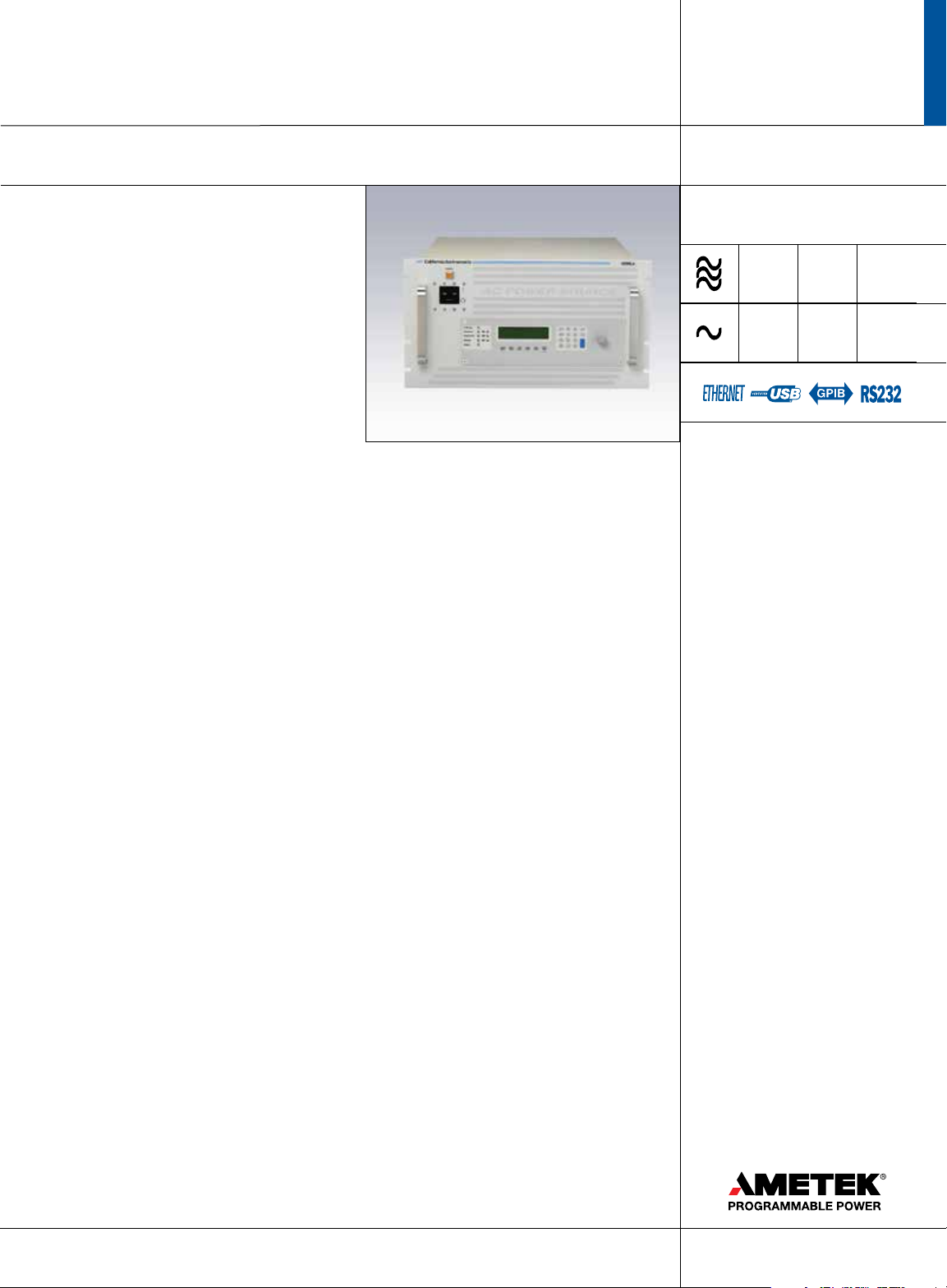
California Instruments Ls Series
3000–18000 VA
3-18 kVA Programmable AC Power Source / Analyzer
• Backward Compatible with L Series
Function and bus compatible with the California
Instruments L Series
• Three phase and Single phase modes
Ideally suited for avionics and defense applications
• 3 kVA to 18 kVA Power Levels
Match power source and cost to application
requirements
• Transient Programming
Test products for susceptibility to AC
line disturbances
• Built-in Measurements
Performs voltage, current, and
power measurements
• Advanced Features
Arbitrary waveform generation, harmonic analysis,
GPIB interface are some of the available options
• Interface
Standard USB & RS232C interface.
Optional GPIB & LAN available
• CE Marked (400V Input model ONLY)
Safe, reliable, and consistent operation
Integrated System
The Ls Series is an improved version of the classic
California Instruments L Series AC power sources.
The Ls Series provides many basic AC source
capabilities at an economical cost. Additional
capabilities such as arbitrary waveform generation
and harmonic analysis can be added as options.
The Ls Series can be ordered in either single
phase (-1) or three phase (-3) congurations.
Power levels range from 3 kVA to 6 kVA in a
single chassis. Multiple chassis can be combined
for power levels up to 18 kVA.
Easy-To-Use Controls
The Ls Series is completely microprocessor
controlled and can be operated from simple front
panel controls. A pair of analog controls located
next to the backlit alphanumeric LCD display
allows output voltage and frequency to be slewed
up or down dynamically. For more advanced
operations, a series of menus is provided using a
dual line high contrast LCD display. An optional
full keypad is available.
Applications
With precise output regulation and accuracy, high
load drive current, multi or single phase mode
and built-in measurement capabilities, Ls Series
AC sources address many application areas of AC
power testing. Additional features such as DO
160, MIL 704, Boeing, or Airbus test standards
are available options that establishes the Ls
Series as a solid choice for avionics or defense
applications. All Ls Series AC sources are standard
equipped with USB and RS232C remote control
interfaces. GPIB and Ethernet (LAN) interfaces are
optional.
Compatibility
Although the standard command language is
SCPI, the Ls Series also offers functional and
bus compatibility with the CI L Series AC power
sources. Using the APE (Abbreviated Plain English)
command syntax, the Ls Series can be used in
existing test systems without having to modify
program code. The APE language is part of the
-GPIB option which includes a GPIB/ IEEE-488
interface.
135–400 V
0–132 A
208 230 400
230
AMETEK
Programmable Power
9250 Brown Deer Road
San Diego, CA 92121-2267
USA
858.458.0223
08192013
179
Page 2
Ls Series
Transient Programming
To simulate common line disturbance
occurrences, the Ls Series offers a list of transient
steps. These steps can be programmed from the
front panel or downloaded over the interface
using the Interface Instrument Control Software
(GUI) program supplied. The GUI allows libraries
of commonly used line disturbances to be created
on disk for quick recall. Once downloaded, the
transient program can be executed from the PC
or from the front panel. AC transient generation
allows the effect of rapid changes in voltage,
frequency, phase angle and waveform shape on
the unit under test to be analyzed. The Ls Series
is available in either three or one phase output
congurations and offers standard voltage ranges
of 135 Vrms and 270 Vrms. A wide range of
options can be added to customize the Ls Series
to meet your specic application requirements.
Voltage Range Options
Output voltage range options are available to
provide higher voltage outputs. In addition to
the standard 135/270 V range pair, 156/312
Vrms (-HV option) or 200/400 Vrms (-EHV option)
can be specied at the time of order. All voltage
ranges are Line to Neutral. On three phase Ls
Series models, maximum Line to Line voltages are
467 V (standard), 540 V (-HV option) and 692 V
(-EHV option).
Phase Mode
The -MODE option provides automatic switching
between three phase and single phase output
modes. In single phase mode, all output current
is routed to the Phase A output terminal.
The -MODE option is available for 3 phase Ls
congurations.
Waveform Generation
The standard Ls Series provides sine wave output
capability. For more demanding test applications,
the advanced option package (-ADV) adds the
following waveform capabilities:
• Squarewave.
• Clipped Sinewave - Simulates THD levels to test
for harmonic distortion susceptibility.
• Harmonic and Arbitrary (User dened)
waveforms.
Using the provided Windows GUI, dening
harmonic waveforms is as easy as specifying the
relative amplitude and phase angle for each of up
to the 50th harmonic. The waveform data points
are generated and downloaded by the ICS to the
AC source through the standard RS232C, USB
or optional LAN or GPIB bus and are retained in
non-volatile memory. Up to 50 waveforms can be
stored and named for easy recall.
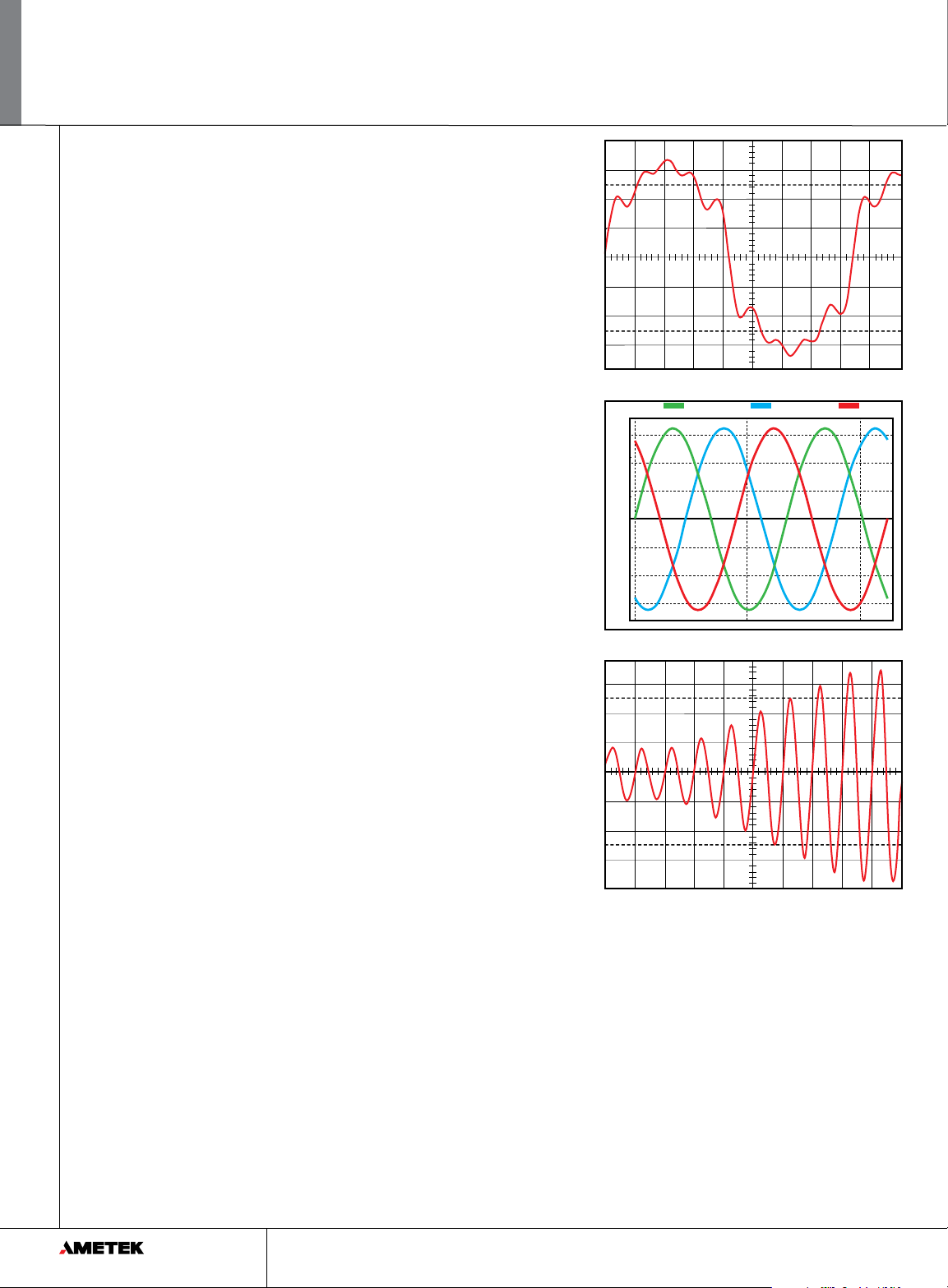
Harmonic waveform, Fund., 3rd, 5th, 7th and 9th.
Phase A
150
100
50
0
Voltage
-50
-100
-150
0.0 ms 1.8 ms 3.7 ms
Three phase output mode.
Voltage sweep transient causes output voltage to change at a
programmed rate.
Phase B Phase C
Ls Series - Measurement and Analysis
The Ls Series measurement system is based
on real-time digitization of the voltage and
current waveforms using a 4K sample buffer.
The digitized waveform data is processed by a
Digital Signal Processor to extract conventional
load values such as rms voltage, rms current,
real and apparent power. With the addition of
the advanced features option. (-ADV option),
the same data can also be used to perform
Fast Fourrier Transformation (FFT) to extract
the harmonic amplitude and phase angle of
50 harmonics, or display acquired voltage and
current waveforms.
www.ProgrammablePower.com180
Page 3
Ls Series
100%
Standard Measurements
The following standard measurements are
available from the front panel or via the bus:
• Frequency and Phase
• Voltage (rms)
• Current(rms) and Peak Current
• Crest Factor
• Real Power and Apparent Power
• Power Factor
Advanced Measurement Functions
(-ADV option)
Power analysis of EUT load characteristics is
available by adding the -ADV option. Harmonics
up to the 50th harmonic (for fundamental
frequencies up to 250 Hz) and total harmonic
distortion of both voltage and current is provided
as well.
Harmonic analysis data can be displayed on the
front panel display or on the PC using the GUI
program. The GUI can also be used to save and
print harmonics data in tabular, bar graph or time
domain formats.
The acquired voltage and current time-domain
waveforms for each output phase can be
displayed using the GUI program. Waveform
displays on the PC. Available display modes
include voltage and current combined, three
phase voltage, three phase current and true
power. The time-domain data is also available
for transfer to a PC through the bus when using
custom software.
Diagnostics Capability
The AC Source can perform a self test and report
any errors. The self test will run until the rst
error is encountered and terminate. The response
to the self test query command will either be the
rst error encountered or 0 if no error was found.
(Self test passed).
Windows Graphical User Interface
A Windows compatible Instrument Control
Software (GUI) offers a soft front panel interface
for operation from a PC. The following functions
are available through this GUI program:
• Steady state output control (all parameters).
• Create, run, save and print
transient programs.
• Measure and log standard measurements.
With -ADV option:
• Generate and save harmonic waveforms.
• Generate and save arbitrary waveforms.
• Capture and display Voltage and
Current waveforms.
• Measure, display, print and log harmonic
voltage and current measurements.
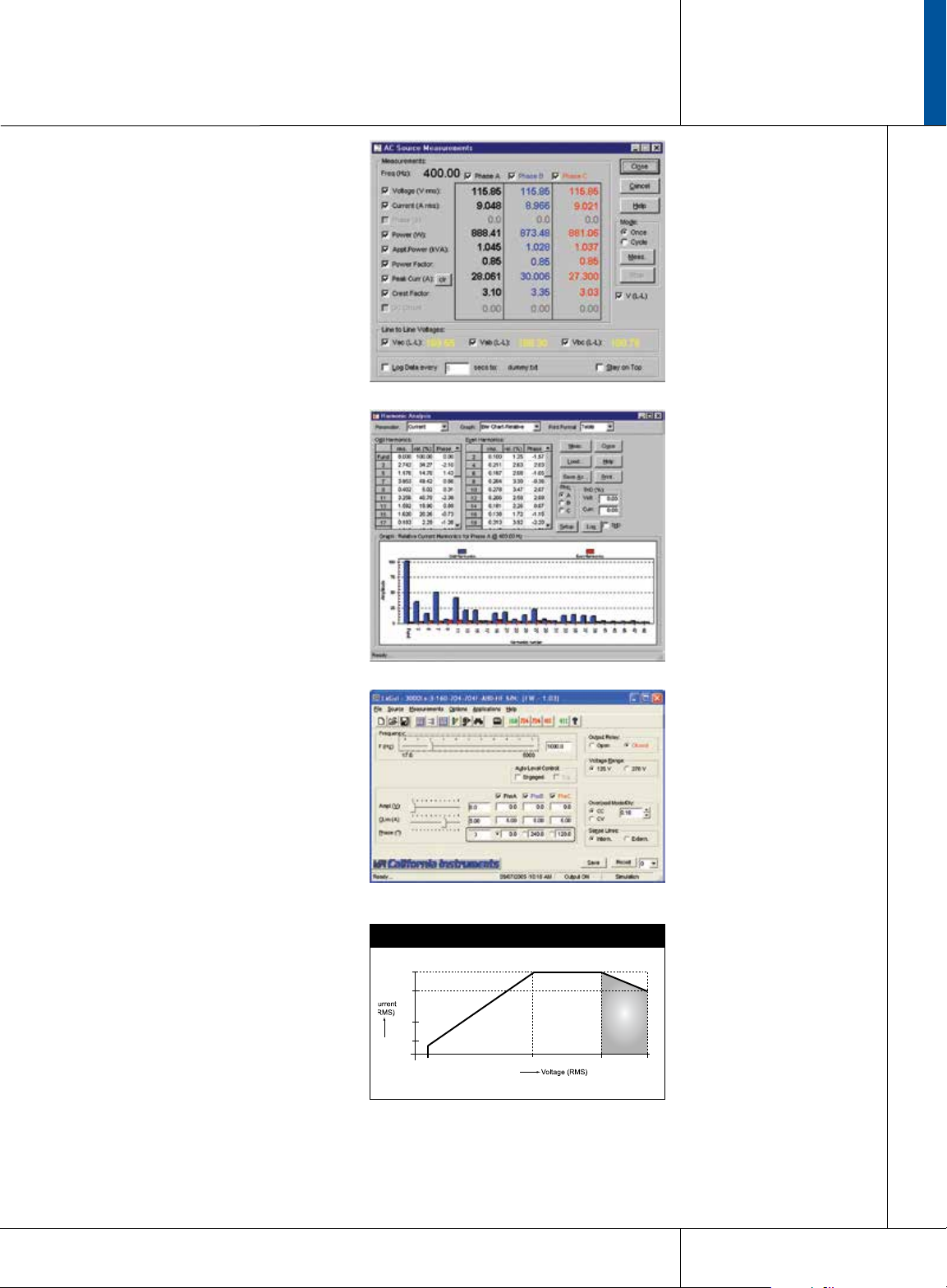
Standard measurements for all phases.
Standard measurements for all phases.
Standard measurements for all phases.
Constant Power AC Mode - Max. AC Current
125%
100%
50%
20%
10% 80%
50%
Power
3000–18000 VA
Full
858.458.0223
181
Page 4
Ls Series : Specications
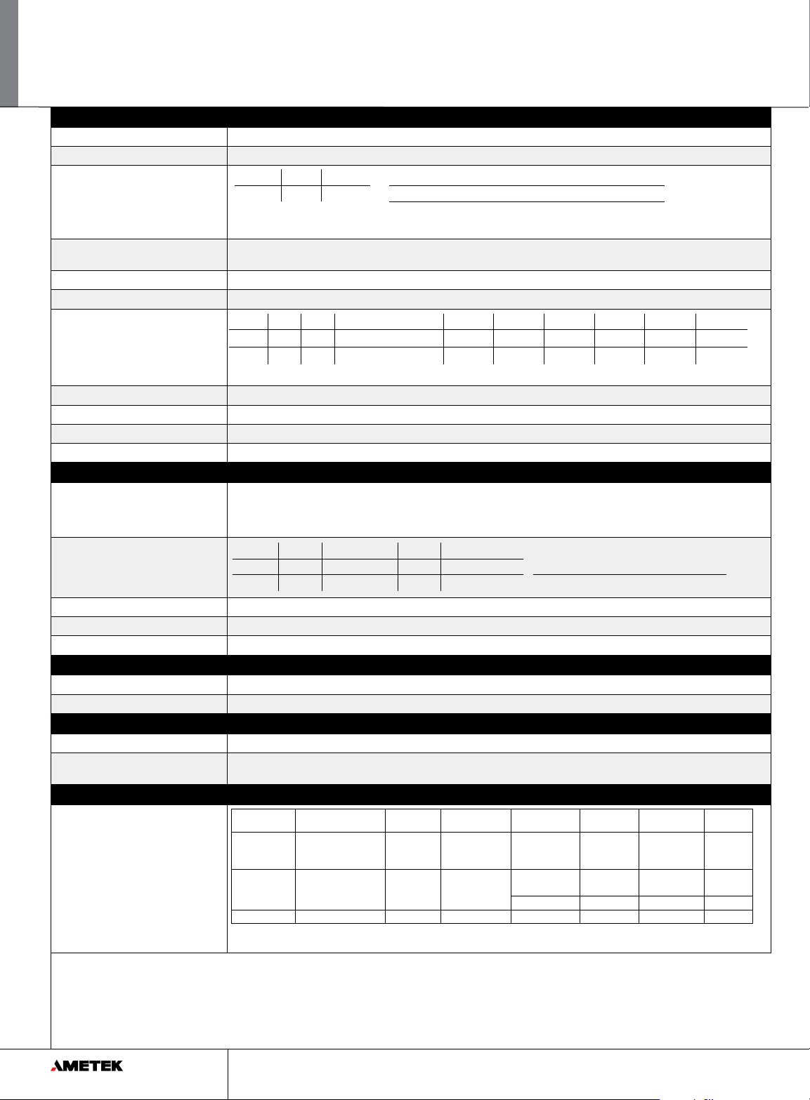
Output
Maximum Power per phase 3000Ls: 1 phase: 3000 VA, 3 phase: 1000 VA; 4500Ls: 1 phase 4500 VA, 3 phase 1500 VA; 6000Ls: 1 phase 6000 VA, 3 phase: 2000 VA
Power factor 0 to unity at full output VA
Voltage Ranges
Range V Low V High VA Programming Resolution 100 mV
AC 0-135V 0-270V Load Regulation < 0.1 % FS
Line Regulation < 0.02 % for 10 % line change
See -HV and EHV options for alternative voltage range pairs.
Programming Accuracy (25°C ±5°C Voltage (rms): ± (0.05% + 0.25) V from 5.0 V to FS; Frequency: ± 0.025 45 Hz - 819.1 Hz, ± 0.7 % > 819.1 Hz; Phase: ± 1° 45-100 Hz,
Frequency Range 45 Hz - 1000 Hz (see -HF option for higher output frequencies) 17 - 45 Hz operation available at reduced voltages
Frequency Resolution 0.01 Hz at < 81.9 Hz, 0.1 Hz at 82.0 to 819.1 Hz, 1 Hz2 at > 819 Hz
Max RMS Current
Current Limit Programmable from 0 Amps to maximum current for selected range
Peak Current 3000Ls: 6 X (lrms @ full scale voltage); 4500Ls: 4 X (lrms @ full scale voltage); 6000Ls: 3 X (lrms @ full scale voltage)
Output Noise 100mV rms typ. (20 kHz to 1 MHz) Harmonic Distortion < 1% (at full scale voltage, full resistive load)
Isolation Voltage 300 V rms output to chassis Output Relay Push button controlled and bus controlled output relay
± (1° + 1°/kHz) 100 Hz-1kHz
V Range V high V low < At Full Power Model 3000Ls-3 Ø 3000Ls-1 Ø 4500Ls-3 Ø 4500Ls-1 Ø 6000Ls-3 Ø 6000Ls-1 Ø
-3 3 ø 7.4 A 14.8 A
-1 1 ø 22.2 A 44.4 A V High
Note: Constant power mode on 3000Ls and 4500Ls provides increased current at reduced voltage; 6000Ls provides maximum voltage.
At FS Voltage >
V Low
7.4 A 22.2 A 11.1 A 33.3 A 14.8 A 44.4 A
3.7 A 11.1 A 5.5 A 16.7 A 7.4 A 22.2 A
Input
Voltage Models 3000Ls, 4500Ls, 9000Ls, 13500Ls: Standard: 208-230 ± 10% VAC, (L-L, 3 Phase); Option -400: 400 ± 10% VAC (L-L, 3 Phase);
Line Current (rms per phase)
Efciency
Power Factor 0.6 typical
Hold-up Time At least 10 ms
Models 6000Ls, 12000Ls, 18000Ls: Standard 208-230 + 10% VAC (L-L, 3 Phase) 450V L-L: Consult factory
Notes: 1. Input must be specied when ordering. 2. -400 option not availble on 6000Ls, 12000Ls, 18000Ls. 3. 3000Ls can be operated from 1 phase AC.
Model 3000Ls 3000Ls (1Phase) 4500Ls 6000Ls (@ 208V) Inrush Current
187 VLL 19 A 32 A 31 A 38 A
360 VLL 10 A n/a 16 A n/a Line Frequency: 47-440 Hz
75% typical
(Per phase):
@ 180-254 V: 50 A peak
@ 360-440 V: 83 A peak
System
Storage Setup: 16 complete instrument setups / Transient List: 100 transient steps per list (SCPI mode) or 16 transient registers (APE mode)
Trigger Input/Output Input: Triggers measurements or transient steps - SMA connector: 10K pull-up / Output: SMA Connector: HCTTL output
Protection
Overload/Temp/Voltage Overload: Constant current or constant voltage mode; Over temperature: Automatic Shutdown; Over voltage: Automatic shutdown
Regulatory/RFI Suppresion IEC1010, EN50081-2, EN50082-2, CE (for 400V input only),
EMC, and safety mark requirements / RIF Suppression: CISPR 11, Group1, Class A
Measurement
Measurements - Standard
(AC Measurements)
Parameter Frequency Phase Voltage (AC) Current (AC rms) Real Power Apparent
Range 45-81.91 Hz
Accuracy* (±)
1 ø mode (-1) 0.1% + 1 digit 0.5° 0.5% + 250 mV 0.1% + 150 mA 0.15% + 9 W 0.15% + 9 VA 0.03
3 ø mode (-3) 2° 0.1% + 50 mA 0.15% + 3 W 0.15% + 3 VA 0.01
Resolution* .01 Hz / 0.1 Hz / 1 Hz 0.1° / 1° 10 mV 1 mA 1 W 1 VA 0.01
* Accurac specications are in % of reading and apply above 100 counts. For multi-chassis congurations, current, power range and accuracy specications are times
three. Power factor accuracy applies for PF > 0.5 and VA > 50% of max. Frequency measurement specication valid for output > 30 Vrms.
82.0-819.1 Hz
> 819 Hz
45-100 Hz
100-1000 Hz
0-400 V 0-50 A 0-6 kW 0-6 kVA 0.00-1.00
Power
Power
Factor
Note: Specications are subject to change without notice. Specications are warranted over an ambient temperature range of 25°± 5° C. Unless otherwise noted, specications
are per phase for a sinewave with a resistive load and apply after a 30 minute warm-up period. For three phase congurations, all specications are for L-N. Phase angle
specications are valid under balanced load conditions only.
www.ProgrammablePower.com182
Page 5

Ls Series : Specications
3000–18000 VA
Remote Control
IEEE-488 Interface (option) IEEE-488 (GPIB) talker listener. Subset: AH1, C0, DC1, DT1, L3, PP0, RL2, SH1, SR1, T6, IEEE-488.2 SCPI Syntax
USB Interface & Ethernet Version: USB 1.1; Speed: 460 Kb/s maximum / Ethernet Interface (Optional): specify -LAN option. 10BaseT, 100BaseT, RJ45
RS232C Interface Bi-directional serial interface; 9-pin D-shell connector. Handshake: CTS, RTS. Databits: 7 w/ parity, 8 w/o parity. Stopbits: 2.
Baud rate: 9600 to 115200. Supplied with RS232C cable / Code and Format: SCPI; APE (option -GPIB)
Physical Dimensions
Dimensions (per chassis) Height: 10.5” (267 mm), Width: 19” (483 mm), Depth: 23.7” (602 mm) (depth includes rear panel connectors)
Weight Chassis: Net: 193 lbs / 87.7 Kg, Shipping: 280 lbs / 127.3 Kg (for /2 or /3 model conguarations multiply number of chassis)
Vibration and Shock Designed to meet NSTA project 1A transportation levels
Air Intake/Exhaust Forced air cooling, side air intake, rear exhaust
Temperature & Diagnostics Temperature: Operating: 0 to 35° C, full power / Storage: -40 to +85° C; Diagnostics: Built-in self test available over bus (*TST)
Rear Panel Connectors * Three phase AC input and output terminal block with safety cover. * IEEE-488 (GPIB) connector (Option -GPIB). * 9-pin D-Shell RS232C
connector (RS232 DB9 to DB9 cable supplied). * Remote Inhibit (INH) and Discrete Fault Indicator (DFI). * Remote voltage sense terminal
block. * Trigger In1 and Trigger Out1. * System interface connectors. * Auxilary Output (Option -AX)
Option -AX Specications
Option -AX Provides seperate isolated 26 VAC regulated and 5 Vac unregulated outputs. The 26 V is normally used for servo-synchro excitation, and
the 5 V for lamp power. 26 Volt-Accuracy: ± 2%. Current capacity: 3 ARMS. Frequency:
360/440 Hz. Regulation ± 0.05%. 5 Volt-Accuracy: ± 5%. Current capacity: 5 ARMS
Option -ADV Specications
Measurements - Harmonics
Waveforms Pre dened: Sine, Square, Clipped User dened, 1024 addressable data points; Storage: 50 user waveforms, non-volatile memory
Data Acquisition Parameters: Voltage, Current time domain, per phase; Resolution: 4096 data points, 10.4 usec (1ø) or 31.25 usec (3ø) sampling interval
Parameter Frequency Fundamental Harmonics Voltage Current
Range 45-250 Hz / 0.09 - 12.5 kHz Fundamental Harmonics 2 - 50 Fundamental Harmonics 2 - 50
Accuracy* (±) 0.01% + 1 digit / 0.5% + 1 digit 750 mV 0.3% + 750 mV+0.3% /1 kHz 0.5 A / 0.3% + 150 mA +0.3% /1 kHz
Resolution 0.01 Hz / 0.1 Hz 10 mV / 10 mV 10 mA / 10 mA
* Accuracy specications are in a percent of reading for single unit in 3-phase mode.
Option -HV Specications
Voltage/Frequency Ranges Low: 0-156 Volt; High: 0-312 Volt / Frequency: With -HF option: 3000Ls, 4500Ls, 6000Ls: 45 Hz - 5000 Hz; 9000Ls, 12000Ls, 13500Ls,
Max RMS Current at Full Power 3 Phase: High: 6.4 A, Low 12.8 A; 1 Phase: High: 19.2 A, Low: 38.4 A; Note: Constant power modes on 3000Ls and 4500Ls. Current
Max RMS Current at FSVoltage 3000Ls: 3 Phase: High: 3.2 A, Low: 6.4 A; 1 Phase: High 9.6 A, Low: 19.2 A; 4500Ls: 3 Phase: High: 4.8, Low 9.6; 1 Phase: High: 14.4 A,
18000Ls: 45 Hz - 5000 Hz
available at reduced voltage for 3000Ls, 4500Ls, and max voltage for 6000Ls
Low: 28.8 A; 6000Ls: 3 Phase: High: 6.4 A, Low 12.8 A; 1 Phase: High: 19.2 A, Low: 38.4 A
Option -EHV Specications
Voltage/Frequency Ranges Voltage: Low: 0-200 Volt; High: 0-400 Volt / Frequency: With -HF option: 45 Hz - 5000 Hz
Max RMS Current at Full Power 3 Phase: High: 5.0 A, Low 10.0 A; 1 Phase: High: 15.0 A, Low: 30.0 A; Note: Constant power modes on 3000Ls and 4500Ls. Current
Max RMS Current at FS Voltage 3000Ls: 3 Phase: High: 2.5 A, Low: 5.0 A; 1 Phase: High 7.5 A, Low: 15.0 A; 4500Ls: 3 Phase: High: 3.8, Low 7.5; 1 Phase: High: 11.3 A,
available at reduced voltage for 3000Ls, 4500Ls, and max voltage for 6000Ls
Low: 22.5 A; 6000Ls: 3 Phase: High: 5.0 A, Low 10.0 A; 1 Phase: High: 15.0 A, Low: 30.0 A
Option -HF Specications
Measurements:
F < 2000 Hz: See standard Ls
Specications;
F > 2000 Hz: See table >
Parameter Frequency Phase Voltage (AC)
Range 45 - 5000 Hz < 2000 Hz
Accuracy* (±)
1 ø mode (-1) 0.1% + 1 digit 0.5° 0.05% + 250 mV 0.5% + 150 mA 0.5% + 9 W 0.5% + 9 VA 0.03
3 ø mode (-3) 5° 0.1% + 0.1%/kHz +300MV 0.5% + 50 mA 0.5% + 3 W 0.5% + 3 VA 0.01
Resolution* 0.01 Hz / 0.1 Hz / 1 Hz 0.1° / 1° 10 mV 1 mA 1 W 1 VA 0.01
* Accurac specications are in % of reading and apply above 100 counts. For multi-chassis congurations, current, power range and accuracy specications are times
three. Power factor accuracy applies for PF > 0.5 and VA > 50% of max. Frequency measurement specication valid for output > 30 Vrms.
> 2000 Hz
0-300 V
< 1000 Hz / > 1000 Hz
Current
(AC rms)
0-50 A 0-5 kW 0-5 kVA 0.00-1.00
Real Power Apparent
Power
Power
Factor
250 mVrms typical (20 kHz to 1 MHz) 3000Ls 34500Ls, 6000Ls: Standard: -HV 45 Hz- 5000 Hz; - EHV: 45 Hz - 5000 Hz
Output Noise 250 mVrms typical (20 kHz to 1 MHz)
© 2009 AMETEK Programmable Power All rights reserved. AMETEK Programmable Power is the trademark of AMETEK Inc., registered in the U.S. and other countries.
Elgar, Sorensen, California Instruments, and Power Ten are trademarks of AMETEK Inc., registered in the U.S.
858.458.0223
183
Page 6
Ls Series
Model¹
Output
Power
No of Output Phases Nom. Input Voltage²
-1 -3
3000Ls 3 kVA 1 3 208-230 V
3000Ls-400 3 kVA 1 3 400 V
4500Ls 4.5 kVA 1 3 208-230 V
4500Ls-400 4.5 kVA 1 3 400 V
6000Ls 6 kVA 1 3 208-230 V
9000Ls/2 9 kVA 1 3 208-230 V
9000Ls/2-400 9 kVA 1 3 400 V
12000Ls/2 12 kVA 1 3 208-230 V
13500Ls/3 13.5 kVA 1 3 208-230 V
13500Ls/3-400 13.5 kVA 1 3 400 V
18000Ls/3 18 kVA 1 3 208-230 V
Note 1: The /2 or /3 designation indicates number of chassis.
Note 2: All input voltage specications are for Line to Line three phase, delta or wye. Model 3000Ls (208 V input) can be operated on 230 V L-N single phase if needed.
HF Table Model Max. Freq.
3000Ls 5000 Hz
4500Ls 5000 Hz
6000Ls 5000 Hz
9000Ls/2 2000 Hz
12000Ls/2 2000 Hz
13500Ls/3 2000 Hz
18000Ls/3 2000 Hz
Ordering Information
Model
Refer to table shown for model numbers and
congurations. Specify number of output phases
(-1 or -3) as part of model number, eg 4500Ls-1
or 4500Ls-3.
Supplied with
User / Programming Manual on CD-ROM,
Software and RS232C serial cable.
Options
Input Options
-400 400 ±10% Volt Line to Line AC input
Includes CE Mark. [Not available on
6000Ls, 12000Ls and 18000Ls Models]
-480 480 ±10% (3 phase output only)
Output Options
-AX Auxiliary outputs, 26 VAC, 5 VAC.
Limits upper frequency to 800 Hz.
-HV 156/312 V output range.
-EHV 200/400 V output range.
-HF Extends upper frequency limit.
See HF table.
-LF Limits output frequency to 500 Hz.
Keypad Options
-KP Upgraded keypad control panel.
-MODE Add phase mode selection for 3 models
-L22 Locking Knobs.
-LKM Clock and Lock Master
-LKS Clock and Lock Auxiliary
-LNS Line Sync.
-EXS External Sync.
Avionics Test Routine Options
-ABD Airbus Directive 0100.1.8 tests.
[AC only]. Requires -ADV and use of
Windows PC and included
LxGui software.
-AMD Airbus AMD24 Test
-A350 Airbus Test Software
-AIRB Airbus A380, A350 & AMD24 package
-704 Mil-Std 704 rev D and E test rmware.
[AC only]
-704F Mil-Std 704 rev A - F
-160 RTCA/DO-160, Change 2,
EuroCAE-14D [Section 16, AC only]
* Note: The comprehensiveness of the tests
that can be performed with avionics options
is determined by the capabilities of the power
source used. Reference the Avionics Software
Manual P/N 4994-971 for denition and
restrictions.
Cabinet Options
-RMS Rackmount Slides. Recommended for
rack mount applications.
C prex Cabinet System. Installed and pre-wired
in 19” cabinet.
Controller Options
-ABL Emulates Elgar SL Series
-ADV Advanced feature set. Adds arbitrary
waveform generation and harmonic
analysis of voltage and current.
-GPIB GPIB interface and APE programming
language.
-LAN Ethernet Interface.
-MB Multi-box. Adds controller to auxiliary
chassis of multi-chassis systems.
www.ProgrammablePower.com184
Option Matrix
HF LF HV EHV LKM LKS EXS AX
HF - X O O X X O X
LF X - O O O O O O
HV O O - X O O O O
EHV O O X - O O O O
LKM X O O O - X O O
LKS X O O O X - X O
EXS O O O O O X - O
AX X O O O O O O -
Note 1: See option matrix
Note2 : -LKS, -LNS and -EXS are mutually exclusive and with
Ext Trig function.
 Loading...