

Caliber CGP42-2G-1SR-N-WH, CGP60-2G-1SR-2SB-L, CGP42-2G-1SR-N, CGP42-2G-1SR-L-WH, CGP60-2G-1SR-2SB-N Installation & Use Instructions
...Page 1

Appliances
42” (3) Burner Pro Built-In Grill
CGP42-2G-1SR-L-(WH)
and CRCD41 Combo 2X Drawer plus Dual Tank/Trash slides.
Caliber Crossame™ Pro Series Outdoor Grills
Models:
42” 3 BURNER GRILL:
CGP42-2G-1SR-L/N-(WH); (2) grill burners, (1) sear burner,(1) rotisserie burner, Wood Handle
Option(WH)
60” 3 BURNER GRILL with integral Dual Power Pro Side Burners:
CGP60-2G-1SR-2SB-L/N-(WH); (2) grill burners, (1) sear burner,(1) rotisserie burner, (2) Power
Pro Side Burners, Wood Handle Option(WH)
Installation + Use/Care Instructions
1
Page 2
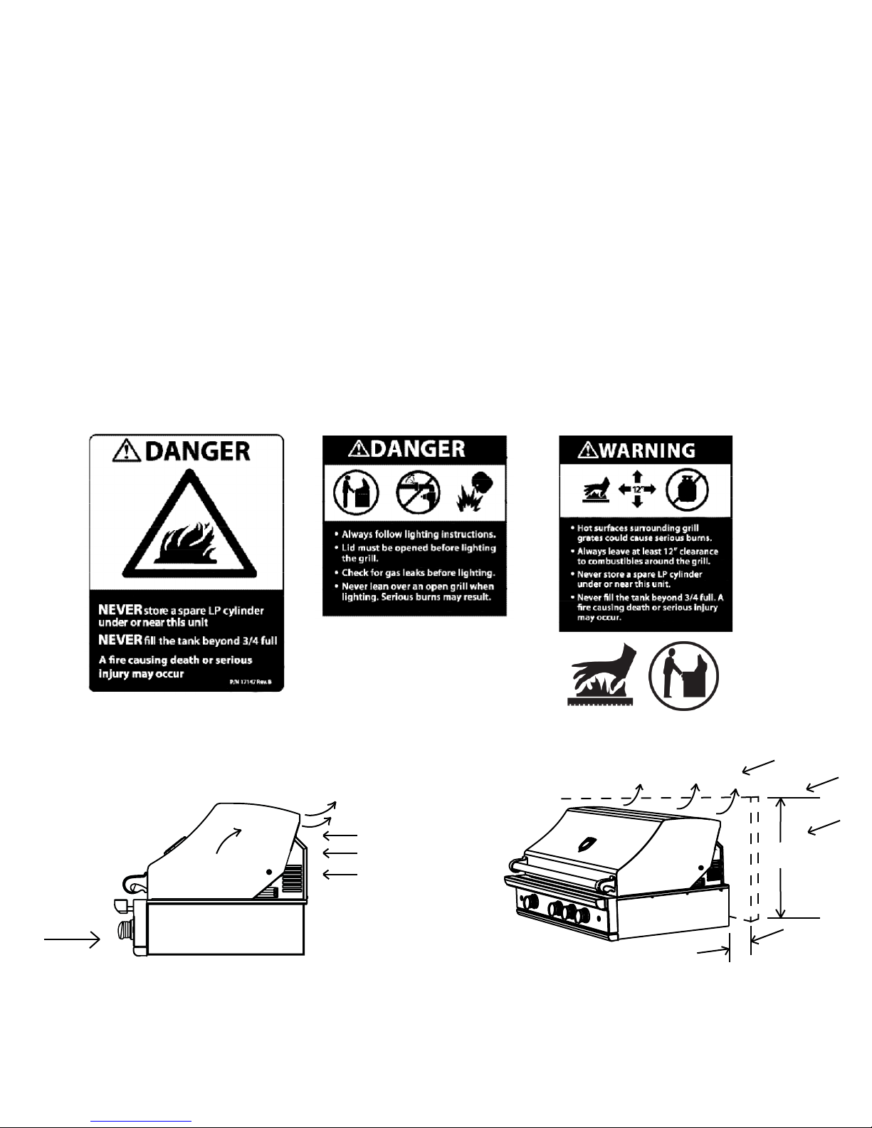
DANGER:
If you smell gas:
1. Shut o gas to the grill.
2. Extinguish any open ame.
3. Open Lid.
4. If odor continues, keep away from the grill
and immediately call your gas supplier or local
re department.
AVERTISSEMENT
S’IL Y A UNE ODEUR DE GAZ:
1. Coupez l’admission de gaz de l’appariel.
2. Éteindre toute amme nue.
3. Ouvrir le couvercle.
4. Si l’odeur persiste, appeler immédiatement votre compagnie
de gaz ou votre département des incendies.
WARNING:
1. Do not store or use gasoline or other ammable liquids or vapors in the vicinity of this
grill or any other appliance.
2. An LP cylinder not connected for use shall
not be stored in the vicinity of this grill or any
other appliance.
IMPORTANT SAFETY NOTICE:
Certain Liquid Propane dealers may ll liquid propane cylinders for use in the grill beyond cylinder lling capacity.
is “Overlling” may create a dangerous condition.
“Overlled” tanks can build up excess pressure. As a safety device, the tank pressure relief valve will vent propane gas
vapor to relieve this excess pressure. is vapor is combustible and therefore can be ignited. To reduce this danger, you
should take the following safety precautions:
When you have your tank lled, be sure you tell the supplier to ll it to no more than 3/4 (75%) of its total capacity.
AVERTISSEMENT
1. Ne pas entreposer ni utiliser de l’essence ni
d’autres vapeurs ou liquides inammables dans le
voisinage de l’appareil, ni de tout autre appareil.
2. Une bouteille de propane qui n’est pas raccordée
en vue de son utilisation, ne doit pas être entreposée dans le voisinage de cet appareil ou de tout
autre appareil.
Do not store a full tank in direct sunlight.
WARNING!
Push and turn the selected burner knob om “OFF” to “HI”. If burner does not light in 4 to 5 seconds turn knob “OFF” and wait
5 minutes before trying again for any accumulated gas to dissipate. Repeat until the burner has lit.
Begin by insuring proper installation and servicing. Follow the installation instructions within this manual. Have your
grill installed by a qualied installer. Have the installer show you where the gas supply shut-o valve is located so that you
know where and how to shut o the gas to the grill. If you smell gas, your installer has not done a proper job of checking
for leaks. If the connections are not perfectly sealed, you can have a small leak and therefore a faint gas smell. Finding a
leak is not a “do-it-yourself ” procedure. Some leaks can only be found with the burner control in the “ON” position and
this must be done by a qualied technician.
» Never aach or disconnect an LP cylinder, or move or alter gas ings when the grill is in operation or is hot.
» Clean and perform general maintenance on the grill twice a year. Watch for corrosion, cracks, or insect activity.
» Check the regulator, hoses, burner ports, air shuer, and venturi/valve section carefully. Always turn o gas at the
source (tank or supply line) prior to inspecting parts.
Page 3

Table of Contents
Pages 3-6
Pages 7-9
Pages 10-14
Pages 15-17
Page 18
Page 19
Pages 20-22
Page 23
Page 24
Page 25
Page 26
Pages 27-28
Care and Safety Precautions
Grill Placement and Installation
Gas Requirements, Pressure Testing and Hookups
Leak Testing
Electrical Connections
Air Shuer Adjustments
Lighting, Match Lighting Instructions
Using the Rotisserie
Using the Power Pro Dual Top Burners
Care and Maintenance
Warranty
Avertissement - Aention - Francais
Page 4
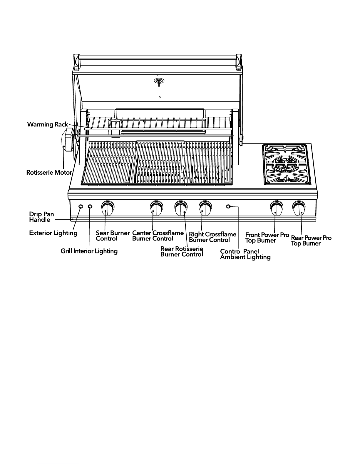
Geing to know your Caliber Grill:
(not all features available on all models - CGP60-2G-1SR-2SB model shown below)
2
Page 5

CARE AND SAFETY PRECAUTIONS
WARNING!
THIS GRILL IS FOR OUTDOOR USE ONLY!
FOR YOUR SAFETY
DO NOT store or use gasoline or other ammable vapors and liquids in the vicinity of this or any appliance.
Tested in accordance with ANSI Z21.58b-2000 CGA 1.6b-M02 for LP and Natural Gas Standard for Outdoor Use Only.
Check your local building codes for the proper method of installation. In the absence of local codes, this unit should be
installed in accordance with the National Fuel Gas Code No. Z223.1-1988 and the National Electrical Coe ANSI/NFPA No.
70-1990.
CALIFORNIA PROPOSITION 65 WARNING!
e burning of gas cooking fuel generates some by-products that are on the list of substances that are known by the State
of California to cause cancer or reproductive harm. California Law requires businesses to warn customers of potential
exposure to these substances. Always operate this unit according to the use and care manual, ensuring you provide good
ventilation when cooking with gas.
WARNING!
SAFETY PCTICES TO AVOID PERSONAL INJURY!
When properly cared for, your Caliber grill will give safe and reliable service for many years. However, extreme care must
be used since the grill produces intense heat and can increase accident potential. When using your grill, basic safety practices must be followed, including but not restricted to the following:
DO NOT aempt to light grill without reading the lighting instructions section of this manual.
Children and pets should not be le alone or unaended in an area where the grill is being used.
FIRST
» Read entire Use and Care Manual carefully and completely BEFORE using your grill for the rst time to reduce the risk
of re, hazard, or other injury.
REPAIR
» Do not repair or replace any part of your grill unless specically recommended in this manual. All other services should
be referred to a qualied service technician.
CHILDREN
» Do not store items of interest to children around or below the grill.
» Never allow children or pets to crawl inside an island enclosure where a grill is placed.
FLAMMABLE MATERIALS
» Never let clothing, pot holders, or other ammable materials come into contact with or close to any hot surface of the
grill until it has cooled. Fabric may ignite and result in personal injury.
» For personal safety, never lean over the grill while in use.
» Wear proper apparel. Loose ing garments or sleeves should never be worn while using this grill. Some synthetic
fabrics are highly ammable and should not be worn while cooking.
COOKWARE
» Only certain types of glasses, heat-proof glass, ceramic, earthenware, or other glazed utensils are suitable for grill use.
Use of these types of materials may break with sudden temperature changes. Use only on low or medium heat seings
according to the manufacturer’s instructions.
» Do not heat unopened food containers as a build up of pressure may cause the container to burst.
PROTECTIVE GEAR
» Protect hands with oven mis when opening and closing the grill lid.
» When using the grill, never touch the grill rack, ame spreader, radiant tray, or immediate surrounding area as these
areas become extremely hot and could cause burns.
3
Page 6

POT HOLDERS
» Use only dry pot holders: moist or damp pot holders on hot surfaces may cause burns from steam. Do not use a towel
or bulky cloth in place of pot holders. Do not let pot holders touch hot portions of the grill rack.
GREASE
» Grease is ammable. Let hot grease cool before aempting to handle it. Avoid leing grease deposits collect at the
boom of the grill. Clean grill aer each use to avoid grease build-up.
AIRFLOW
» Do not use aluminum foil to line the grill racks or grill boom. is can severely upset combustion airow or trap excessive
heat in the control area. e result of this can be melted knobs, melted igniters and wiring, and increase the chance of per-
sonal injury.
» For proper lighting and performance of the burners, keep the burner ports clean. It is necessary to clean them periodi-
cally for optimum performance. e burners will only operate in one position and must be mounted correctly for safe
operation.
CLEANING
» Clean the grill with caution. Avoid steam burns; do not use a wet sponge or cloth to clean the grill while it is not. Some
cleaners produce noxious fumes or can ignite if applied to a hot surface.
» Be sure all grill controls are turned o and the grill is cool before using a type of aerosol cleaner on or around the grill.
e chemical that produces the spraying action could, in the presence of heat, ignite or cause metal parts to corrode.
EXCESSIVE FAT
» Do not use the grill to cook excessively fay meats or products that promote are-ups.
COMBUSTIBLES AND LOCATION
» Do not operate the grill under unprotected combustible construction. Use only in well ventilated area.
» Do not use the grill on boats, recreation vehicles, or in buildings, garages, sheds, breezeways, or other such enclosed
areas.
» Keep the area surrounding the grill free from combustible materials, trash, or combustible uids.
» Do not obstruct the ow of combustions and ventilation.
» Always adhere to the specied clearances. Combustible locations (rear, 18” and side 20”).
STOGE
» If storing the unit indoors, ensure that it is cool. If an LP tank is used, the cylinder must be unhooked and stored out-
side in a well-ventilated area, out of the reach of children.
SAFETY
» Keep all electrical cords and fuel supply hoses away from the heated areas of the grill.
» Never use a dented or rusty LP tank.
» e Natural Gas pressure regulator or LP Regulator hose assembly supplied with this unit must be used. Contact Cali-
ber Appliances for replacement parts.
4
Page 7

WARNING!
Spiders and insects can nest in the grill burners , causing gas not to ow through the burner. e gas will ow from
the front of the burner into the control panel. is is a very dangerous condition which can cause a re to occur
behind the valve panel, thereby damaging the grill components and making it unsafe to operate. If this occurs, call for
service immediately.
WARNING!
Keep the area surrounding the grill free from combustible materials, trash, or combustible uids and vapors such as
gasoline or charcoal lighter uid. Do not obstruct the ow of combustion and ventilation air.
WARNING!
Never use the grill in windy conditions. If located in a consistently windy area (oceanfront, mountaintop, etc.) a wind
break will be required. Always adhere to the specied clearances listed.
» Aer a period of storage or non-use (such as over the winter), the gas grill should be checked for gas leaks, deteriora-
tion, proper assembly, and burner obstructions before using.
» Never lean over an open grill. When lighting a burner, always pay close aention to what you are doing. Be certain you
are pushing the ignition buon when you aempt to light the grill.
» Aer lighting burners, make sure burners are operating normally.
» When using the grill, do not touch the grill burner, grate, or immediate surrounding area as these areas become ex-
tremely hot and could cause burns.
» When using the side burners always use at boomed pans which are large enough to cover the side burner. Adjust the
ame so that it heats only the boom of the pan to avoid ignition of clothing. Position handles inward away from open
edges of the unit to avoid burns associated with unintentional spill overs. Hold the handle of the pan to prevent move-
ment of it when turning or stirring food. For proper lighting and performance of the burners keep the ports clean. It is
necessary to clean periodically for optimum performance.
» Clean the grill with caution. Avoid steam burns; do not use a wet sponge or cloth to clean the grill while it is hot. Some
cleaners produce noxious fumes or can ignite if applied to a hot surface.
» Be sure all grill controls are turned o and the grill is cool before using any type of aerosol cleaner on or around the
grill. e chemical that produces the spraying action could, in the presence of heat, ignite or cause metal parts to cor-
rode.
» Do not use the grill for cooking excessively fay meats or products which promote are-ups.
» Never grill without the drip pan and grease tray in place and pushed all the way to the back of the grill. Without it hot
grease could leak downward and produce a re or explosion hazard.
» Do not operate the grill under unprotected combustible construction. Use only in well ventilated areas. Do not use in
buildings, garages, sheds, breezeway, covered structure or other such enclosed areas. is unit is for outdoor use only.
» If a cart unit is stored indoors, ensure that it is cool, fold the side shelf down, then push, never pull, the grill and never
push or pull on the side shelves. If LP, the cylinder must be unhooked and the LP cylinder stored outside in a well
ventilated area, out of reach of children.
» Never use the grill in a windy area.
» Do not use charcoal or lighter uid in the outdoor grill.
» Keep any electrical supply cord, or the rotisserie motor cord away from the heated areas of the grill and water
(pools, fountains, puddles).
» Never use a dented or rusty LP tank. Keep the ventilation openings of the cylinder enclosure free and clear from de-
bris.
» Use only dry pot holders; moist or damp pot holders on hot surfaces may cause burns from steam. Do not use a towel
or bulky cloth in place of pot holders. Do not let pot holders touch hot portions of the grill or burner grate.
» Have an ABC rated Fire Extinguisher accessible – never aempt to extinguish a grease re with water or other liquids.
5
Page 8
» To avoid burns when cooking, use long handled BBQ tools.
» Do not move the appliance during its use.
» is unit is for outdoor use only! Do not operate in enclosed areas. is could result in carbon monoxide build-up
which would result in injury or death.
» When using a grill, be sure that all parts of the unit are rmly in place and that the grill is stable (can’t be tipped over).
» To put out are-ups, adjust the controls to lower the temperature
» CALIFORNIA PROPOSITION 65-WARNING: e Burning of gas cooking fuel generates some by-products which
are
on the list of substances which are known by the State of California to cause cancer or reproductive harm. California
law requires businesses to warn customers of potential exposure to such substances. To minimize exposure to these
substances, always operate this unit according to the Use and Care Guide, ensuring you provide good ventilation when
cooking with gas.
» is outdoor cooking gas appliance is not intended to be installed in or on recreational vehicles, trailers and/or boats.
Note:
is product must be installed by a licensed plumber or gas er when installed within the Commonwealth of Massachuses.
GRILL PLACEMENT
GRILL EXHAUST
EXH AUST
PREFERRED
AIR FLOW
6
Wind hiing the grill
while in use, especially
winds blowing into or
across this hood rear
gap may cause poor
burner performance,
and in some cases may
cause the control panel
to get excessively hot
EXHAUST VENT FLOW
WIND
15”
MINIMUM
WIND SCREEN
5 ”
MINIMUM
NOTE: If wind against the rear of the unit is an issue, a wind screen
should be added behind the grill to block rear wind. e noncombustible wind screen should be built taller than the top of the
ue opening at the back of the grill (15” min) and have a lid opening
clearance of a minimum of 5
above.
” from the rear of the grill as shown
Page 9
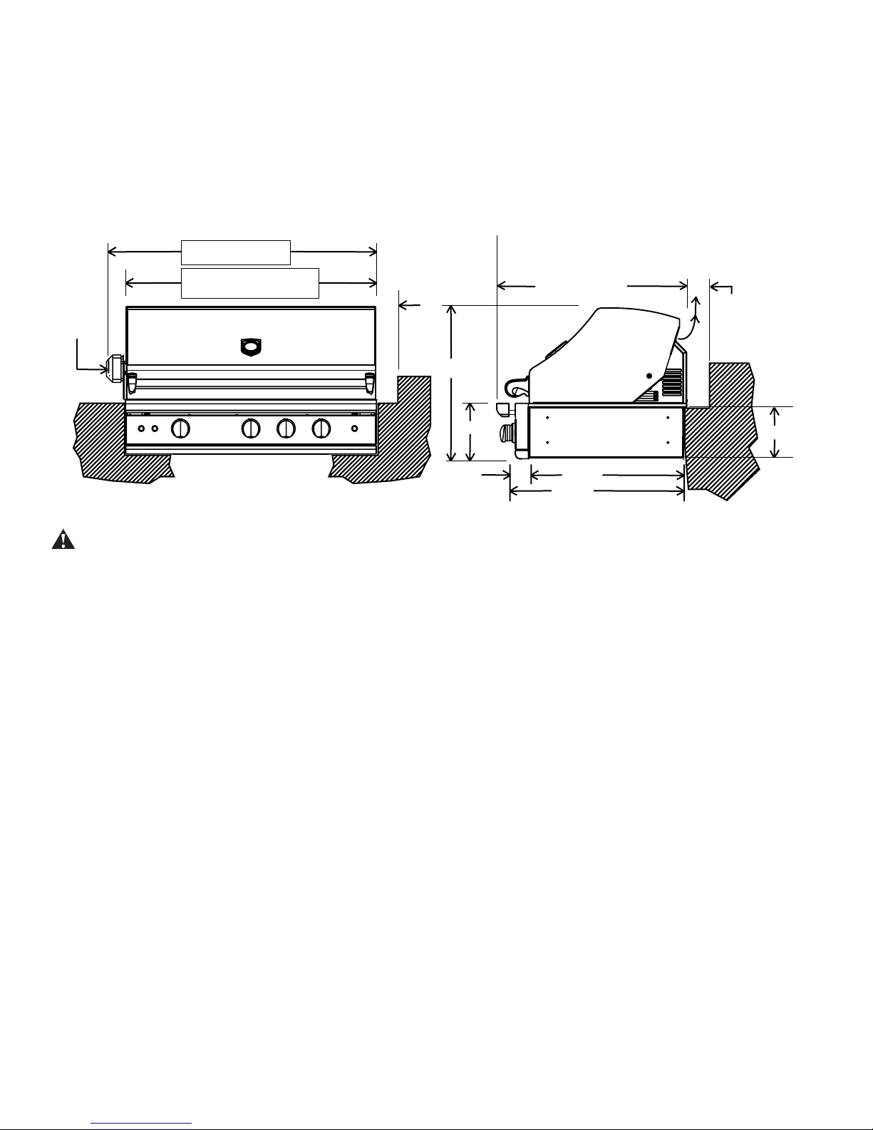
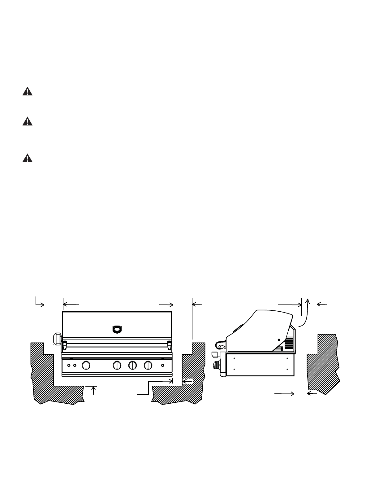
GRILL PLACEMENT AND INSTALLATION
Clearance to non-combustible construction*:
A minimum of 3” clearance from the back of the grill to non-combustible
construction is required for the lid to open freely. It is desirable to allow at least 6” rear and side clearance to noncombustible construction above the cooking surface for counter space. If you’ll be using the rotisserie option, the space is
essential for motor and skewer clearance. e grill can be placed directly adjacent to non-combustible construction below the cooking surface. (Fig.03)
Clearances to Non-Combustible Construction*
24¼”
26¼”
grill exhaust
5”
MINIMUM
to non-combustible
construction/minimum
lid open clearance
1/2
8
”
rotisserie
motor
CGP60 models = 63”
CGP42 models = 45½”
CGP60 models = 59½”
CGP42 models = 42”
(without rotisserie motor mounted
3½”
24
1/4
”
9”
2¼”
29¾” closed
31¼” plate rail extended
Important! Gas ings, regulator, and installer supplied shut-o valves must be easily accessible.
WARNING!
DO NOT install the grill in combustible enclosures. e Grill must be installed into a NON-Com-
bustible enclosure
LOCATION
» When selecting a suitable location, take into account concerns such as exposure to wind, proximity to trac paths, and
keeping gas supply lines as short as possible.
» When determining a suitable location take into account concerns such as exposure to wind, proximity to trac paths
and keeping any gas or electrical supply lines as short as possible and away from heat sources. Locate the grill only in
a well ventilated area. Do not build the grill under overhead unprotected combustible construction. Never locate the
grill in a building, garage, breezeway, shed or other such enclosed areas. During heavy use, the grill will produce a lot of
heat and smoke. Ensure there is adequate area for it to dissipate.
» If locating the grill in a windy area, try to locate the grill so the prevailing wind will blow air at the front of the grill.
is will assist the grill in venting hot air thru the back of the grill. In addition, this will help keep any smoke from
blowing at someone who is cooking on the grill. If you have to locate the grill in a windy area where the prevailing
wind is at the rear of the grill, a windbreak must be installed. e windbreak should be made such that it will block
wind from entering the exhaust vent in the rear of the unit.
» As high-performance gas appliance, your grill requires signicant amounts of air to support the combustion process.
Your grill is designed to take air in through the valve panel area, and send the exhaust products out through the exhaust
gap at the rear of the hood. Using your grill in windy conditions can disrupt the proper ow of air though your grill,
leading to reduced performance, or in certain severe cases, causing heat buildup in the valve panel area. is can lead to
problems such as having the knobs melt, or burn hazards when the valve panel surfaces become too hot to touch.
» During high wind conditions, it is best if you don’t use your grill. If you live in an area that is subject to frequent high
winds, or a steady directional wind, then the installation of a suitable windbreak may be advised. If you have a grilling
cart, it is best to position the unit so the prevailing wind blows into the valve panel, thus supporting the proper airow.
Winds hiing the back of the grill directly are the most likely to cause problems, although wind blowing along the
exhaust gap in the rear can also be problematic.
Please note that damage to your grill resulting from use in windy conditions, such as melted knobs or igniter wires, or
valve panel discoloration from heat build-up, are excluded from warranty coverage.
7
Page 10
During heavy use, the grill will produce considerable smoke. therefore, locate the grill in a well-ventilated area.
Never locate the grill in a building, garage, breezeway, shed or other such enclosed areas without an approved
ventilation system for outdoor use.
If installing grill in an island in an open area, without suitable protection om windy conditions, a windbreak MUST be created
to ensure proper performance of the grill. If installation does not conform with manufacturer’s guidelines, your warranty will be
voided.
WARNING!
Failure to maintain required clearances creates a re hazard that may result in property damage or
serious personal injury.
WARNING!
Grill is designed to function in an open area. Recommended minimum clearances should be maintained to all surfaces
(combustible and noncombustible) for optimum performance. Noncombustible material within the minimum clearance area
could result in discoloration or deterioration.
WARNING!
If a noncombustible material such as stucco is covering a combustible material such as wood, the minimum clearance
distance needs to be held to the wood. e presence of a noncombustible material inside the clearance zone does not
eliminate the minimum clearance zone to combustible material.
* DEFINITION OF NONCOMBUSTIBLE MATERIAL - Material which is not capable of being ignited and burned,
such as materials consisting entirely of, or a combination of, steel, iron, brick tile, concrete, slate, and plaster.
Clearances to Combustible Construction**:
Minimum of 12” from the sides and rear of grill must be maintained to adjacent vertical combustible construction, above
the counter top level. You should take in account that there is a large volume of heat, and smoke will exhaust from the rear
of the grill. is may discolor or damage unprotected areas (Fig. below). Do not install under unprotected combustible
construction without using a re safe ventilation system. A 6” minimum clearance must be maintained under the counter
top to combustible construction. e clearance can be modied by a use of an insulated jacket.
12 ” MINIMUM
to combustible
construction
6 ” MINIMUM
to combustible
construction below
countertop surface
12 ” MINIMUM
to combustible
construction
6 ” MINIMUM
to combustible
construction below
countertop surface
grill exhaust
24 ” MINIMUM
to combustible
construction
** DEFINITION OF COMBUSTIBLE MATERIAL
Any materials of a building structure or decorative structure made of wood, compressed paper, plant bers, vinyl/plastic
or other materials that are capable of transferring heat or being ignited and burned. Such material shall be considered
combustible even though ame-proofed, re-retardant treated, or painted surface or plastered.
8
Page 11

GRILL PLACEMENT AND INSTALLATION - cont’d
e grill is designed for easy placement into built-in masonry enclosures. For non-combustible applications the grill drops
into the opening shown below and hangs from its side anges. A deck is not required to support it from the boom.
A carpenter’s “spirit level” should be used to assure that the unit is level both front-to-back and side-to-side. If it
is not level, burner combustion may be erratic or the unit may not function eciently for grease ow. If the oor
is uneven or has a decided slope, re-leveling may be required aer each moving of a freestanding unit.
Important!
It is required that a minimum of (3) 10 sq. inches of ventilation opening be provided for both the le and right sides, as well
as the back of enclosure (Figs. below), in order to safely dissipate unburned gas vapors in the event of a gas supply leak.
WARNING!
Note specic built-in enclosure ventilation requirements. See text and illustrations below.
Standard layout for non-combustible enclosure
Build-in planning guide for non-combustible enclosures*
grill exhaust
5 ”
MINIMUM
to non-combustible
construction/minimum
lid open clearance
18” min to combustible
construction-rear
1/2
8
”
24
1/4
”
9”
2¼”
29¾” plate rail closed
31¼” plate rail extended
24¼”
26¼”
5 3/4” Minimum to
non-combustible
construction to
allow for opening
of lid
10 square inches
Minimum ventilation
required for each side
of the enclosure
9
Page 12

GAS REQUIREMENTS
Verify the type of gas supply to be used, either natural or LP, and make sure the marking on the appliance rating plate
agrees with that of the supply. e rating plate is located underneath the unit boom. Never connect an unregulated gas
line to the appliance. You must use the gas regulator provided with the unit, even if the supply is controlled.
An installer-supplied gas shut-o valve must be installed in an easily accessible location. All installer supplied parts must
conform to local codes, or in the absence of local codes, with the National Electrical Code, ANSI/NFPA 70 or the Canadian Electrical Code, CSA C22.1, and the National Fuel Gas Code, ANSI Z223.1 or CAN/CGA-B149.1 Natural Gas
Installation Code or CAN/CGA-B149.2 Propane Installation Code.
All pipe sealants must be an ap proved type and resistant to the actions of LP gases. Never use pipe sealant on are
ings. All gas connections should be made by a qualied technician and in accordance with local codes and ordinances.
In the absence of local codes, the installation must comply with the National Fuel Gas Code ANSI Z223.1. Gas conversion kits are available from the factory. When ordering gas conversion kits, have the model number, and the type of gas
(natural or LP) from your grill.
TOTAL GAS CONSUMPTION OF THE GRILL WITH ALL BURNERS ON HI:
{ CGP42 models - 92,000 Btu/hr, CGP60 models - 128,000 Btu/hr }
e appliance and its individual shut-o valve must be disconnected from the gas supply piping system during any pressure testing of that system at test pressures in excess of 1/2 PSIG (3.5 kPa.) e appliance must be isolated from the gas
supply piping system by closing its individual manual shut-o valve during any pressure testing of the gas supply piping
system at test pressures equal to or less than 1/2 PSIG (3.5 kPa.). e installation of this appliance must conform with
local codes or, in the absence of local codes, with the National Fuel Gas Code, ANSI Z223.1. Installation in Canada must
be in accordance with the Standard Can1-b149.1 and/or .2 (installation code for gas burning appliances and equipment)
and local codes.
NATUL GAS HOOK UP: (THIS TYPE OF CONNECTION
SHOULD BE PERFORMED BY A CERTIFIED OR
LICENSED TECHNICIAN ONLY.)
Connection: 1/2” NPT male with 3/8” are adapter. Operating
pressure: 4.0” W.C. Supply pressure: 5” to 14” water
column. If in excess of 14” W.C., a step down regulator
is required. Check with your local gas utility company or
local codes for instructions on installing gas supply lines.
Be sure to check on type and size of run, and how deep to
bury the line. If the gas line is too small, the grill will not
function properly. Any joint sealant used must be an approved
type and be resistive to the actions of LP gases.
TO HOOK-UP THE FIINGS SUPPLIED
WITH THE GRILL:
Assemble as shown in the illustration to the right.
Use threading compoundon male threads only. Do not use
threading compoundon the male end of the 1/2 NPT to
3/8 are adapter. Use a second pipe wrench to hold the grill
inlet pipe to avoid shiing any internal gas lines of the grill.
Ensure that the regulator arrow points in the direction of gas
ow towards the unit, away from the supply. Do not forget to place the
installer-supplied gas valve in an accessible location.
LP GAS HOOK UP (TYPE 1 OR QCC1 REGULATOR):
Grills oriced for use with LP gas come equipped with a
high capacity hose/regulator assem bly for connection to
a standard 20 lb. LP cylinder (Type 1).
e LP tank is not included.
10
Coupling
1/2” NPT x 2.0”
Nipple
Regulator 4.0” W.C.
1/2”NPT x 5.0” Nipple
Adapter 1/2”NPT to t 3/8” are
ing
*Installation must conform with local codes or with
the National Fuel Gas Code ANSI Z223.1 or the
CAN/CGA Propane Installation Code
reading compound must be
resistant to LP gas
Do not put threading
compound on these
threads
Page 13

42” GRILL LP GAS HOOK UP (TYPE 1 OR QCC1 REGULATOR):
Grills oriced for use with LP gas come equipped with a high capacity hose/regulator assem bly for connection to
a standard 20 lb. LP cylinder (Type 1). e LP tank is not included.
Connection:
1/2” NPT male with a 3/8” Flare adapter (included). LP Hose with a quick disconnect and ings are
included. Operating pressure: 11.0” W.C.
CAUTION!
Before connecting LP tank to regulator, check that all grill burners and side burners, smokers, and rotisserie valves
are in the OFF position and open grill lid.
To connect the LP regulator/hose assembly to the tank/valve assembly, rst make sure the main valve on the tank is
completely closed. Although the ow of gas is stopped when the Type 1 system is disconnected as part of of its safety
feature, you should always turn o the LP tank main valve aer each use and during transport of the tank or unit. Insert
the regulator inlet into the tank valve and turn to the black coupler clockwise until the coupler tightens up. Do not overtighten the coupler. Turn the main tank valve on and turn the burner control valves on the unit to the “HI” position for
about 20 seconds to allow the air in the system to purge, turn valves o and wait 5 minutes before aempting to light the
burners.
To disconnect the coupler, rst make sure the main tank valve is turned o. Grasp the coupler and turn counter clockwise. e inlet will then disengage. Remove the inlet from the tank valve opening if it has not already done so when it
disengaged. Your local LP lling station should be equipped with the proper equipment to ll your tank.
LP TANK REQUIREMENTS:
A dented or rusty LP tank may be hazardous and should be checked by your LP supplier. e cylinder that is used must
have a collar to protect the cylinder valve. Never use a cylinder with a damaged valve. Always check for leaks aer every LP tank change. e LP gas cylinder must be constructed and marked in accordance with the specications for LP
gas cylinders of the U.S. Department of Transportation (DOT or CAN/CSA-B339) and designed for use with a Type
1 system only. Do not change the regulator/hose assembly from that supplied with the unit or aempt to use a Type 1
equipped regulator/hose assembly with a standard 510 POL tank/valve assembly. e cylinder must be provided with
a shut-o valve terminating in an LP gas supply cylinder valve outlet specied, as applicable, for connection Type 1. If
the appliance is stored indoors, the cylinder must be disconnected and removed from the appliance. Cylinders must be
stored outdoors in a well-ventilated area out of the reach of children.
Note:
When an LP unit is being directly connected to an LP house
system, you must follow the natural gas hook up guidelines.
e installer must provide the proper gas regulator to reduce
the gas ow to 11” W.C.
Note:
e Grill comes with the LP Regulator/Hose assembly installed
at the factory. e assembly, along with the entire Grill system,
is leak tested. Do not remove the Regulator/Hose assembly
from the Grill during installation.
1/2” female NPT from unit
WARNING
:
» Do not remove the Grill from the pallet until you are
ready to install.
connection to 3/8” male
are of L.P. hose assy
Type 1 Regulator
» Do not place the Grill directly on the ground or any other
at surface without support. is will prevent damaging
the regulator/hose assembly by the weight of the grill.
» Check the hose, regulator and connectors for damage.
Look for cracks, abrasions, brileness, holes, dents and nicks.
» Do not aempt to remove, repair, or replace the Regulator/
Hose assembly by yourself. It must be done by a
qualied licensed technician only.
Boom of unit
LP Regulator hose
assembly 11” W.C.
Main Tank Valve
20 lb LP Tank
*Installation must conform with local codes or with
the National Fuel Gas Code ANSi Z223.1 or the
CAN/CGA-B149.2 Propane Installation Code
11
Page 14

LP TANK RESTINT FOR BUILT-IN INSTALLATION
If the grill is to be installed in a Built-in application, then the grill must be installed in accordance with the Built–in installation guidelines. If you intend to operate your Built-in grill on LP gas utilizing a 20 lb Type 1 cylinder, then the Built-in
LP tank restraint must be installed prior to initial use of the grill.
e following steps will illustrate how to properly locate and install the LP tank restraint within the Built-in enclosure.
NOTE:
e grill comes with the LP Regulator/Hose assembly installed at the factory. e assembly, along with the entire grill
system, is leak tested. Do not remove the Regulator/Hose assembly from the grill during installation.
Fold down LP Tank restraint harness
over top of the LP tank as shown
Once the LP Tank Harness of ed over the
LP cylinder collar as shown, screw the included LP regulator hose assembly to the LP
tank, open LP cylinder top valve and check
for system leaks before lighting the grill
12
Page 15

60” GRILL LP GAS HOOK UP (TYPE 1 OR QCC1 REGULATOR):
e Caliber 60” Grill oriced for use with LP gas come equipped with a high capacity hose/regulator assembly for connection to a standard 20 lb. LP cylinder (Type 1). e LP tank is not included.
Connection - See diagram below:
(1) 45 deg Elbow ing, (1) Tee ing to connect to 45 deg elbow and ex line, (1) 90 deg Elbow ing 1/2FTP-3/8
Flare 45 deg that mates to the secondary manifold inlet at the Right hand side of the grill under the Dual Power Pro Top
burners, and (1) 3/8” dia x 48” length Flex Line(ALL included) which connects the le and right hand side grill manifold
inputs. LP Hose with a quick disconnect and ings are included. Operating pressure: 11.0” W.C.
CAUTION!
Before connecting LP tank to the Dual Stage regulator, check that all grill burners and side burners, and rotisserie valves
are in the OFF position and open grill lid.
To connect the LP regulator/hose assembly to the tank/valve assembly, rst make sure the main valve on the tank is
completely closed. Although the ow of gas is stopped when the Type 1 system is disconnected as part of of its safety
feature, you should always turn o the LP tank main valve aer each use and during transport of the tank or unit. Insert the
regulator inlet into the tank valve and turn to the black coupler clockwise until the coupler tightens up. Do not overtighten
the coupler. Turn the main tank valve on and turn the burner control valves on the unit to the “HI” position for about 20
seconds to allow the air in the system to purge, turn valves o and wait 5 minutes before aempting to light the burners.
To disconnect the coupler, rst make sure the main tank valve is turned o. Grasp the coupler and turn counter clockwise.
e inlet will then disengage. Remove the inlet from the tank valve opening if it has not already done so when it disengaged.
Your local LP lling station should be equipped with the proper equipment to ll your tank.
60” GRILL LP GAS HOOK UP:
NO.
13
Page 16

PRESSURE TESTING AND HOOKUPS
CAUTION! Use grill only in NON-COMBUSTIBLE enclosures. DO NOT build grill into a combustible enclosure.
PRESSURE TESTING
» e appliance and its individual shut o valve must be disconnected from the gas supply piping system during any
pressure testing of that system, at test pressures in excess of 1/2 PSIG (3.5 kPa).
» e appliance must be isolated from the gas supply piping system by closing its individual manual shut-o valve during
any pressure testing of the gas supply piping system at test pressures equal to or less than 1/2 PSIG (3.5 kPa).
LOCAL CODES
» e installation of this appliance must conform to local codes. In the absence of local codes refer to the National Fuel
gas Code, ANSI Z223.1a-1998.
» Installation in Canada must be in accordance with the Standard Can1-b149.1 and/or .2 (installation for gas burning
appliance and equipment) and local codes.
NATUL GAS HOOK-UP
» Natural gas: manifold connection 1/2” NPT male with 1/2” coupling.
» Operating Pressure: 4.0 WC Supply pressure 5” to 14” W.C.
» If in excess of 14” WC, a step down regulator is required.
» Check with your local gas utility or with local codes for instructions or for installing gas supply lines.
FIINGS SUPPLIED WITH GRILL
» To hook up the ings supplied with grill, use threading compound on male thread only. Do not use threading com-
pound on the male end of 1/2” NPT to 3/8” are adaptor. Use second pipe wrench to hold the grill inlet pipe to avoid
shiing any internal gas lines of the grill. Ensure that the regulator arrow points in the direction of the gas ow towards
the unit. AWAY from the supply. Do not forget to place the installer supplied gas shut-o valve in an accessible location.
PARTS SUPPLIED WITH UNIT
» (1) Nat Gas Regulator - 42” Grill, (2) Nat Gas Regulators - 60” Grill (60” Grill has 2 rear inlets, L/R side of the grill)
» (2) 1/2” NPT Nipple
» Not used with natural gas 1/2 coupler should be supplied also a 82108LP GAS HOOK-UP
» Never connect an unregulated gas line to the grill. LP unit grills come equipped with a high capacity hose/regulator
assembly (Type 1 QCC1) for connection to a standard 20LB LP cylinder (type 1). e LP tank is NOT included. Do
not place the tank directly beneath grill. If the unit is to be hard-piped to an external LP supply, contact your local gas
utility company for instructions in installing this appliance.
» Operating pressure: 10” WC
» To avoid heat degradation (loss of heat) keep the supply as short as possible
LP TANKS
» A dented or rusty LP tank may be hazardous and should be checked by your LP cylinder supplier. Never use a cylinder
with a damaged valve.
» e LP gas cylinder must be constructed and marked in accordance with the specications for LP gas Cylinders of the
US department of Transportation (DOT).
» e cylinder must be provided with a shut-o valve terminating in an LP gas supply cylinder valve outlet specied, as
applicable, for connection type QCC-1 in the standard for compressed gas cylinder valve outlet and inlet connection
ANSI/CGA-V-1.
NOTE: e LP Tank is NOT INCLUDED with the grill and must be purchased separately from your local LP cylinder supplier.
14
Page 17

LEAK TESTING
GENEL
» Although all gas connections to the grill are leak tested at the factory prior to shipment, a complete gas tightness check
must be performed at the installation site due to possible mishandling in shipment, or excessive pressure unknowingly
applied to the unit. Periodically check the whole system for leaks, or immediately check if the smell of gas is detected.
BEFORE TESTING
» Make sure all packaging has been removed
» Do Not smoke while testing
» Never leak test with an open ame
e outdoor gas appliance (grill, side burners, wok) and its individual shut-o valve must be disconnected from the gas
supply piping system during any pressure testing of that system in excess of 1/2” PSI (3.5 kPa).
e outdoor gas appliance (grill, side burners, wok) must be isolated from the gas supply piping system by closing its
individual manual shut-o valve during any pressure testing of the gas supply piping system at pressures equal to or less
than 1/2 PSI (3.5 kPa).
Make a soap and water solution of one part liquid detergent and one part water. You will need a spray bole, brush or rag,
to apply solution to the ings. For LP units, check with a full cylinder. Leak check the regulator to tank connections with
a soap and water solution before operating.
TO TEST
WARNING: Do not use the grill until all connections have been checked and DO NOT leak.
Make sure all control valves are in the “OFF” position. Turn the gas supply “ON”. Check all connections from the supply
line, or LP cylinder up to and including the manifold pipe assembly. Apply the solution around the connection, valve, and
tubing. Soap bubbles will appear where a leak is present. If a leak is detected, immediately turn “OFF” the gas supply, and
tighten any leaking ings. Turn gas “ON” and recheck.
If a gas leak is present, and you cannot stop the leak, immediately turn “OFF” the gas supply and call your local gas sup
plier or installer who installed the appliance. Only authorized factory parts, or parts recommended by the manufacturer
should be used on the grill.
NOTE: Substitution of Parts Will Void e Warranty!
NOTE: Always check for leaks aer EVERY LP tank change.
IMPORTANT
» Check all gas supply ings for leaks before each use. It is handy to keep a spray bole of soapy water near the shut-o
valve of the gas supply line. Spray all the ings. Bubbles will indicate where leaks are located.
» e disconnected LP cylinders must have threaded valve plugs tightly installed, and must not be stored in a building,
garage, or any other enclosed area. e gas must be turned o at the supply cylinder when the unit is not in use.
» If the grill is stored indoors, the cylinder MUST BE disconnected and removed from the grill. Cylinders must be
stored outdoors in well ventilated areas, out of the reach of children and pets.
-
15
Page 18

Check all gas supply ings for leaks before each use:
42” Grill LP Gas:
LEAK TEST POINTS
LEAK TEST
POINT
42” Grill Nat. Gas:
LEAK TEST POINTS
LP TANK
LEAK TEST POINTS
LEAK TEST
POINTS
16
NG SAFETY
SHUT OFF VALVE
LEAK TEST POINT
Page 19

LEAK TESTING - cont’d. 60”GRILLS:
60” Grill Nat. Gas:
LEAK TEST
POINT
LEAK TEST
POINT
NATURAL GAS
CONFIGURATION
LEAK TEST
POINT
SHUT OFF VALVE
TO NATURAL
GAS SUPPLY
MAIN GAS
SUPPLY
60” Grill LP Gas:
LEAK TEST
POINT
PROPANE TANK
2 STAGE
REGULATOR
LP GAS
CONFIGURATION
LEAK TEST
POINT
HOSE KIT
P/N: 12081
17
Page 20

ELECTRICAL CONNECTIONS
GENEL
» e Caliber Crossame Pro Grill is equipped with a 110V electronic ignition system along with 12V panel lighting
and interior/exterior lighting. Included with each Pro Grill is an electrical box that is pre-wired and ready for connecting to the 2 leads from the grill (110V(#2 in the illustration) and 12V(#1 in the liiustration)).
» CART-GRILL HEAD INSTALLATION - For CART mounted grill models, the electrical connector box comes pre-
mounted to the back panel of the cart.
» BUILD-IN ISLAND INSTALLATION - For ISLAND installation planning, mount the box in a well protected, dry
location near the rear of the grill where the box 12V and 110V leads will reach the connector leads from the grill.
» ere is a single 110V lead(#3 in the illustration) coming from the boom of the supplied electrical connection box
which should be plugged into an installer provided GFI circuit in the grilling island enclosure or GFI wall outlet from
the grilling cart.
» See the illustration below regarding wire connections for the Pro 42 & 60” Grill.
TO 12Vdc CONNECTOR
ON GRILL HEAD
1
BACK MOUNTS TO WALL
BELOW GRILL ENCLOSURE
OR TO CART INNER
BACK PANEL
2
FROM GRILL HEAD
110Vac
3
TO 110Vac GFI
18
Page 21

AIR SHUER ADJUSTMENTS
BURNER AIR SHUER ADJUSTMENT
» Each burner air shuer is tested at the factory prior to shipment; however, variations in the local gas supply may make
it necessary to adjust the air shuers. e ames of the burners should be visibly checked.
» Flames should be BLUE and stable with no yellow tips, free of excessive noise or liing. If any of these conditions
exist, check if the air shuer or burner ports are blocked by dirt, debris, spider webs, leaves, etc. and proceed with air
shuer adjustment.
» e amount of air that is pulled through a burner is governed by a sheet-metal cup at the inlet of the burner, called an
air shuer. It is locked in place by a set screw which must be loosened prior to lighting the burner for adjustment.
» e air shuer adjustment screws are accessible with a screwdriver.
» Remove the burner by loosening the bracket and nut that holds it securely towards the back of the burner.
» Loosen the lock screw of the air shuer. Make certain that the burners are siing properly around the orices and then
light the burners.
WARNING!
If the burner is not siing around the orice, you will experience a FLASHBACK where ames will shoot out into the
rebox. is is a VERY dangerous situation that could lead to serious injury and damage your appliance.
To adjust grill burner ame, be advised to adjust according to the following directions. Be careful as the burner may be
very hot. Always use protective gloves or oven mis to protect hands from hot burners.
PROBLEM
YELLOW FLAMES: indicates insucient air.
SOLUTION
Turn the air shuer counter clockwise to allow for MORE air to the burner.
PROBLEM
NOISY FLAME: indicates too much air.
SOLUTION
Turn the air shuer clockwise, until stable blue ame is obtained. Note: you will need to do this repeatedly to ensure
proper ame color and height.
PROBLEM
LIFTING FLAMES: indicates too much air
SOLUTION
Turn the air shuer clockwise, until stable blue ame is obtained. Note: you will need to do this repeatedly to ensure
proper ame color and height.
19
Page 22

LIGHTING INSTRUCTIONS
BEFORE TURNING ON THE BURNERS
» Ensure that all packaging material has been removed
» Ensure that the grill has been leak tested and is properly located
» Check that the radiant trays and grill racks are properly seated
» Light one burner at a time by turning the desired burner to HI and you will hear a continuous click and the burner
should immediately light (for detailed lighting instructions refer to “LIGHTING THE GRILL” section below).
» When all burners are on, preheat the grill for 5 minutes
» Keep the lid closed during the preheat time
» Place the food on the grill and cook to desired length of time
» Adjust the heat seing if necessary
» DO NOT LEAVE THE GRILL UNAENDED WHILE COOKING!
» For are-ups, keep a spray bole of water nearby and douse are-ups with water.
LIGHTING THE GRILL
Each burner is rated at 28,000 BTUs. e grill burners encompass the entire cooking area and are top ported to maximize
heat eciency while the stainless steel radiant covers assure burner protection from falling grease and debris. ese stainless steel radiants are seated above the burners. TO LIGHT THE GRILL: Push in and turn the desired burner control
knob to the le (HI) position. As you turn the knob you will hear clicking of the igniter. If you do not see the burner
ignite when turning the knob to the HI position, tun the knob OFF, wait 5 minutes before aempting to light again to
allow any gas to dissipate. Once you have waited 5 minutes, turn to HI again, listen for the igniter clicking until the burner
has ignited.
NOTE that on rst use or when an LP tank has been replaced that there may be air in the gas line that needs to be purged,
so the push and turn to HI may need to be repeated several time to purge the line of air.
PRE-LIGHTING CHECKLIST
» Ensure that all internal packaging has been removed.
» Make sure the burners have been leak tested and are properly located and held down via the bracket at the back of the
burner.
» Check that the radiant trays and grill racks are properly seated on their front and rear mounting pins.
» Inspect the gas supply piping or hose prior to turning the gas “ON”. If there is evidence of cuts, wear, or abrasion, it
must be replaced prior to use.
» DO NOT use the grill if the odor of gas is present. e pressure regulator supplied with the grill must be used.
Substitutions will void the warranty and may make the grill dangerous to use, causing serious injury.
» If a replacement regulator is required, please contact the dealer, or factory for replacement.
» Screw the regulator (type QCC1) into the tank cylinder valve. Leak test the hose and regulator connections with a
soap and water based solution prior to operating the grill.
LIGHTING THE MAIN BURNERS
Turn all knobs to “OFF” position. Turn the gas supply ON. Always keep your face and body away from the grill when
lighting. Open the lid, push and turn the control knob from “OFF” to the “HI” position. You will hear a continuous
“clicking” sound that indicates the igniter is ring. At the same time the electrode will ignite gas collecting in a small box
over the burner. When using the grill for the rst time or aer changing out an LP tank, it may be necessary to turn the
knob from “OFF” to “HI” for an extended period of time (but never over 10 seconds) to purge the gas line of air. If it
does not light in 4 seconds, turn all knobs to the “OFF” and wait 5 minutes to allow any accumulated gas to dissipate.
20
Page 23

TO MATCH LIGHT THE GRILL
If the burners do not light aer several aempts, then the grill burners, rotisserie burner, or side burners(on some models) may be match lit using a long stem match and the provided match holder arm.
Aach the match to the lighter arm which is aached to the drip pan handle and light it.
Pass the lit match through the notch in the front of the grill rack, keeping your hand and face away from the grill area
while pushing and turning the grill knob 90 degrees to the HI position.
You should hear and see the burner light.
If the burner does not light within 4 seconds, turn the knob to the OFF position and wait 5 minutes before aempting to
light the burner again.
Below:
To match Light the rear Rotisserie burner
NOTE: e rear rotisserie burner may be dicult to light in windy conditions.
21
Page 24

TO MATCH LIGHT THE GRILL(continued)
Below:
To match Light the Power Pro Top Burner (Single or Dual)
Below:
To match Light the Grill Sear Burner
USING THE GRILL
Grilling requires high heat for searing and proper browning. Most foods are cooked at the “medium” seing for the entire
cooking time. However, when grilling large pieces of meat or poultry, it may be necessary to turn the heat to a lower
seing aer the initial browning. is cooks the food thoroughly without burning the outside. Foods cooked for a long
time or basted with a sugary marinade may need a lower seing near the end of the cooking time.
22
Page 25

USING THE ROTISSERIE
TO LIGHT ROTISSERIE (if equipped)
Open the lid, push and turn the knob to the “HI” position. You will hear a single snap sound at the burner control knob
which is the ignition switch sending a spark to the ame electrode mounted under the stainless steel box to the le of
the rotisserie burner. It may take several on/o rotations for gas to reach the burner. Once lit, turn the control knob
to desired seing. If the burner does not light within (5) seconds, turn the control knob to “OFF” and wait 5 minutes
before aempting to light the burner again.
If aer several aempts to light the burner are unsuccessful, you may aempt to match light the Rotisserie burner:
To Match Light the Rotisserie burner: (see picture previous page for reference)
Aach the match to the lighter arm which is aached to the drip pan handle and light it.
As shown in the picture from the previous page, pass the lit match across the stainless steel box located to the le of the
rear rotisserie burner keeping your hand and face away from the grill area while pushing and turning the grill knob 90
degrees to the HI position.
You should hear and see the burner light.
If the burner does not light within 4 seconds, turn the knob to the OFF position and wait 5 minutes before aempting to
light the burner again.
USING THE ROTISSERIE
» Minor rotisserie motor assembly is required
» Remove motor and bracket from protective wrapping
» Remove nuts and screws on bracket and insert screws on bracket and insert screws with bracket aached into holes on
le side of the grill body.
» Replace nuts and tighten.
Note: e rotisserie motor must be electrically grounded in accordance with local codes, or in the absence of local codes,
with the National Electrical Code, ANSI / NFPA 70 - 1990.
METHOD
» Skewer meat onto rotisserie rod and position forks to secure the meat. Tighten L-Screws to rod.
» It is recommended that any meat placed on the rotisserie rod be tied down via string.
» Place a rotisserie pan beneath the food to collect juices and drippings for basting and gravy.
» Light the rotisserie burner as described in the section titled “To Light Rotisserie” above.
» Once lit the burner will reach it’s cooking temperature in approximately 1 minute.
» e rotisserie motor is capable of turning up to a 20 LB cut of meat or poultry.
» For additional room for larger cuts of meat, remove the grill racks and place the rotisserie basting pan directly atop the
radiant trays.
» NEVER use the rotisserie and grill burners at the same time.
IMPORTANT: Keep the rotisserie motor electric cord away from the heated surfaces of the grill.
Note: When not in use, remove the rotisserie motor and store in a dry location.
WARNING! ELECTRICAL GROUNDING INSTRUCTIONS: e rotisserie motor is equipped with a three-prong
(grounding) plug for your protection against shock hazard, and it should be plugged directly into a properly grounded
three-prong receptacle. DO NOT cut or remove the grounding prong from this plug.
23
Page 26

USING THE POWER PRO™ TOP BURNERS
TO LIGHT THE POWER PRO™ TOP BURNER (if equipped)
Note: On most models there is a front and rear burner operated with independent knobs. When lighting these Top
Power Burners, make sure that you are using the intended knob for ignition and use of the front or rear burner.
Open the grill lid, remove the Power Pro™ Top Burner metal cover and push and turn the knob to the “HI” position. You
will hear a continuous clicking sound at the burner which is the ignition switch sending a spark to the ame electrode
mounted in the center of the burner. It may take several on/o rotations for gas to reach the burner. Once lit, turn the
control knob to desired seing. If the burner does not light within (5) seconds, turn the control knob to “OFF” and wait
5 minutes before aempting to light the burner again.
If aer several aempts to light the burner are unsuccessful, you may aempt to match light the Power Pro™ Top Burner.
To Match Light the Power Pro™ Top Burner: (see picture on page 21 for reference)
Aach the match to the lighter arm which is aached to the drip pan handle and light it.
As shown in the picture from the previous page, pass the lit match across the burner ports of the Power Pro™Top Burner
keeping your hand and face away from the burner area while pushing and turning the grill knob to the HI position.
You should hear and see the burner light.
If the burner does not light within 4 seconds, turn the knob to the OFF position and wait 5 minutes before aempting to
light the burner again.
24
Page 27

CARE AND MAINTENANCE
GRILL CKS
It is recommended that the grill racks be cleaned immediately aer grilling, AFTER the ame has been turned o. Be
sure to wear a barbecue mi to protect your hands from the heat and steam. Dip a wire brush in tap water and scrub
the hot grill racks. Steam created as water contacts the hot grill racks assists the cleaning process by soening any food
particles. e particles will fall on the radiant tray and burn away. Cleaning the grill is usually more dicult if the grill has
been allowed to cool.
Tip: You may also try and clean the grill by using a half cut lemon and wipe the grill racks. e acidity in the lemon
breaks up the grease and fat deposits that have collected on the grill racks.
STAINLESS STEEL
e grill is made from non-magnetic stainless steel. ere are many dierent types of stainless steel cleaners available.
Always use the mildest cleaning procedure rst, rubbing in the direction of the grain and NEVER in circular paern. To
touch up
noticeable scratches in the stainless steel, sand very lightly with dry 200 grit emery paper in the direction of the grain.
Specks of grease can gather on the surface of the stainless steel and bake into the surface giving the appearance of rust.
For its
removal use an abrasive pad in conjunction with a stainless steel cleaner. When not in use, the grill must be covered to
protect it from the elements.
IMPORTANT: Failure to rub with the grain can and will cause damage.
GRILL BURNERS
Frequency of cleaning will depend upon how oen you use the grill. Ensure that the gas supply is “OFF” and all knobs
are in the “OFF” position. Extreme care should be used when removing any burner for cleaning. e burner should be
replaced correctly onto the orice before any aempt is made to relight the grill.
IMPORTANT: Make sure the grill is cool before aempting to replace and clean burners.
BURNER CLEANING
Clean burner exterior with a wire brush. Clear stubborn scale with a metal scrapper. Clear any clogged ports with a
straightened paper clip. Never use a wooden toothpick as it may break o and clog the port. Shake out any debris through
the air shuer. Use a ashlight to inspect the burner inlet to ensure it is not blocked. If obstructions can be seen, use a
straightened out wire coat hanger to remove the obstruction.
ORIFICE CLEANING
With the burner removed, remove the orice and shine a ashlight through the openings to ensure there is no blockage.
Use a needle to clear any debris. Be extremely careful not to enlarge the hole or break o the needle.
REASSEMBLING BURNERS
Replace the burner by sliding the air shuer side over the brass orice and the other side in the burner guide. At the same
time, slide the screw on the burner into the hole of the burner bracket and tighten the nut.
NOTE: It is extremely important to center the burner on the orice properly.
Be careful not to upset the air shuer’s original position (unless readjusting air shuer). Make sure it is level and does not
rock. Replace the radiant trays, making sure that they sit level and do not rock. Light all the burners and check for proper
ame characteristics.
25
Page 28

WARNTY
LIMITED LIFETIME WARNTY: Caliber Appliances warrants the brass or stainless steel burners, grill racks and
fabricated stainless steel components to be free from defects in materials and workmanship under normal residential use
for the lifetime of this product. Defective parts will be repaired or replaced free of charge with the owner paying all other
costs including freight and labor. is warranty excludes normal discoloration, surface scratches, grease buildup, weather
and atmospheric related staining, and minor surface rust and oxidation that can be expected on any outdoor product.
FIVE YEAR LIMITED WARNTY: Caliber Appliances warrants the Crossame radiant trays, gas valves, sear zone
burners, and rotisserie burners to be free from defects in materials and workmanship under normal residential use for a
period of ve years from the original date of purchase. Any part determined by Caliber to be defective will be repaired or
replaced free of charge with the owner paying all other costs including freight and labor.
ONE YEAR FULL “IN-HOME” WARNTY: Caliber Appliances warrants the entire product and all of the component parts to be free from defects in materials and workmanship under normal residential use for a period of one year
from the original date of purchase. Caliber will repair or replace, at its option, any part which is determined by Caliber to
be defective during this warranty period at no cost to the original purchaser. Warranty service must be rst authorized by
Caliber and then performed by an authorized service representative during normal business hours. Any non-authorized
service costs will not be covered by this warranty.
NINETY DAY “TDE PROFESSIONAL” WARNTY: is warranty applies to installations where the use of the
product exceeds that of normal residential use but does not reasonably experience the heavy use found in commercial
cooking establishments (as determined by Caliber). Examples of this type of use include country clubs, community
“common” areas, bed & breakfasts, re stations, and other locations where the product is used extensively. Caliber will
at its option repair or replace any defective part with the owner paying for all other costs including freight and labor.
WARNTY DEFINITIONS, LIMITATIONS & EXCLUSIONS:
Coverage Area & Term:
e warranty shall apply only to products purchased and located in the United States and Canada. e warranty
coverage period commences from the original date of purchase and proof of date of purchase is required. In order to
activate the warranty coverage term you need to return the “Warranty Card” supplied with each product or submit this
information online. is card (with the aached serial number label) must be promptly returned to Caliber in order to
ensure warranty coverage. e warranty applies to the original owner only and may not be transferred; however, the warranty is still valid to the original owner even if the product is relocated (excluding transit damage). Caliber will not sell,
share or otherwise distribute information supplied on the warranty cards.
Exclusions:
is warranty does not apply to the commercial use of products (as determined by Caliber) or damages resulting from
improper installation, including failure to provide proper wind breaks and protection for the product from excessive
wind. e warranty also does not apply to product damaged in shipping, transit, or on-site handling during installation.
Warranty is also voided in cases of negligence, alteration, misuse, abuse, accident, natural disaster, loss of electrical power
to the unit for any reason, improper installation, improper operation, unauthorized adjustments or calibrations, dings,
dents, scratches, or damages related to the use of harsh cleaning chemicals and acids. Caliber shall not be liable for
incidental, consequential, special or contingent damages resulting from its breach of this wrien warranty or any implied
warranty. Some states do not allow limitations on how long an implied warranty lasts, or the exclusions of or limitations
on consequential damages. is warranty gives you specic rights and you may have other rights which vary from state
to state. is warranty does not cover travel costs to isolated geographic locations of two hours time both ways or
locations only accessible by plane, train, boat, ferry, etc.
WARNTY SERVICE AND REPLACEMENT PARTS:
Call your authorized dealer or Caliber Appliances directly at 714-848-1349 during normal business hours. Be prepared
to provide the following information: purchasers’ and dealer name, model and serial number of the grill, date of purchase
and an accurate description of the problem. Caliber will not pay for service calls for correcting an improper installation
or for educating the owner/user. e owner is responsible for proper installation, cleaning, providing normal care and
maintenance, providing proof of purchase and providing access to the grill for any service calls.
26
Page 29

AVERTISSEMENT
S’IL Y A UNE ODEUR DE GAZ:
» Coupez l’admission de gaz de l’appariel.
» Éteindre toute amme nue.
» Ouvrir le couvercle.
» Si l’odeur persiste, appeler immédiatement votre compagnie de gaz ou votre département des incendies.
AVERTISSEMENT
» Ne pas entreposer ni utiliser de l’essence ni d’autres vapeurs ou liquides inammables dans le voisinage de l’appareil, ni
de tout autre appareil.
» Une bouteille de propane qui n’est pas raccordée en vue de son utilisation, ne doit pas être entreposée dans le voisinage
de cet appareil ou de tout autre appareil.
Pour utilisation à l’extérieur seulement. Si l’appareil est entreposé à l’inérieur, enlever les bouteilles et les laisser à l’extérieur.
» Lire les instructions avant d’allumer l’appareil.
» Ouvrir le couvercle avant d’allumer l’appareil.
» Si l’appareil ne s’allume pas immédiatement, fermer le robinet du brûleur, aendre 5 minutes puis procéder
de nouveau à l’allumage.
» Dégagement minimal à respecter entre les côtés et l’arriére de l’appareil et une construction combustible adjacente
située audessous de la partie supérieure de l’appareil, soit _ pouces des côtés et _ pouces de l’arriére.
» Dégagement horizontal minimal à respecter entre les côtés et l’arriére de l’appareil et une construction combustible
verticale adjacent dépassant la partie supérieure de l’appareil, soit _ pouces des côtés et _ pouces de l’arriére.
» Il est interdit d’installer le présent appareil au-dessous des surfaces combustibles non protégées.
<<MISE EN GARDE>>: Le régulateur de pression de gaz prévu avec cet appareil de cuisson à gaz pour l’extérieur
doit être utilisé. Ce régulateur est réglé pour une pression de sortie de....pouces de colonne d’eau (La pression de sortie
spéciée par le manufacturier).
DANGER - Gaz inammable sous pression. Au contact d’une amme, toute fuite de gaz de pétrole liquié (GPL)
risque de provoquer un incendie ou une explosion. Pour toute réparation ou pour se débarrasser de cee bouteille ou du
GPL inutilisé, s’adresser au distributeur de GPL.
N’utiliser qu’à l’extérieur seulement*. Ne pas utiliser ni entreposer la bouteille dans un bâtiment,
un garage ou un local fermé.
AVERTISSEMENT:
Savoir reconnaître l’odeur du GPL. Si vous entendez un siement ou si vous sentez une fuite de GPL, demander
immédiatement à toutes les personnes présentes de s’éloigner de la boutielle et appeier le service d’incendie.
Ne pas essayer de la réparer.
» Mise en garde au distruteur de GPL:
» Purger la bouteille de son air avant de la remplir pour la premiére fois.
» Ne pas remplir la bouteille au-delà du niveau permis.
» Contrôler la date de réinspection.
» Le GPL étant plus lourd que l’air, il peut s’accumuler prés du sol avant de se dissiper.
» Tout contact de la peau avec la phase liquide de la bouteille causera des brûlures par le froid.
27
Page 30

» Empêcher les enfants de manipuler la bouteille ou de jouer avec.
» Lorsque la bouteille n’est pas raccordée à l’appareil, en maintenir fermé le robinet. Pour les appareils de cuisson auto-
nomes d’exténeur, utiliser une bouteille d’une capacité maximale de 9 kg (20 lb).
» Ne pas utiliser, entreposer ou transporter la bouteille en l’exposant à une température excessive car la soupape de
sûreté risque de s’ouvrir et de laisser échapper une grande quantité de gaz inammable.
» Pour transporter une bouteille de GPL, la maintenir solidement xée en position verticale avec le robinet fermé.
POUR BNCHER LA BOUTEILLE:
» Se conformer strictement aux codes en vigueur.
» Lire et appliquer les instructions du manufacturier.
» Consulter les instructions relatives au branchement de la bouteille (fournies avec l’appareil).
» S’assurer que l’évent du régulateur n’est pas vers le haut.
» Fermer tous les robinets de l’appareil.
» Ne pas se servir d’une allumee ou d’une amme nue pour vérier la présence d’une fuite. Enduire les zones marquées
d’un <<X>> d’eau savonneuse. Ouvrir le robinet de la bouteille. Si une bulle se forme, refermer le robinet et faire appel
à un spécialiste de l’entretien. Avant d’allumer l’appareil s’assurer systématiquement que les robinets en raccords de
l’aapareil ne fuient pas.
» Pour allumer l’appareil, suivre les instructions du manufacturier.
» Lorsqu’on ne se sert pas de l’appareil, maintenir le robinet de la bouteille fermé.
» N’enlevez pas, ne détériorez pas et n’eacez pas cee étiquee
*Sous réserve des normes ANSI/NFPA 58 OU CAN/CGA-B149.2.
28
Page 31

Page 32

CALIBERAPPLIANCES.COM
Caliber Appliances 17812 Metzler Lane, Huntington Beach, California 92647 USA Part # 30335 10/2017
(714) 848-1349
Because of continuous product improvement, Caliber reserves
the right to modify any product specications. All material
contained herein may not be reproduced without prior wrien
consent of Caliber Appliances. Copyright 2017
 Loading...