

Page 1

Thank you for choosing a Caliber product.In doing so you’ve demonstrated a
desire to own the finest in Car Audio Technology. Caliber strives to provide you
with the finest products possible, and is always looking for ways to please our
customers even more.
Properly installed,your Caliber amplifier will provide years of high quality sonic
reproduction.Before installing the amplifier in your v ehicle,please read this entire manual carefully,in order to protect your vehicle,and get the maximum performance of your mobile sound system.
Caliber W arranty
Due to the complexity of our products,we strongly recommend that this amplifier is installed by your authorized Caliber dealer. If properly installed by your
dealer we provide a warranty for 12 month from the date of purchase.
If you install this amplifier yourself,we wish you lots of fun and succes in doing
so.If you follow our guidelines,you’ll get the best result.Our warranty,however,
will be limited to and not exceed 30 days from the date of purchase.
Caliber Accessories
To realize the exceptional performance of which this amplifier is capable, it is
necessary that power sources,signal sources, speakers and interconnects are of
the highest quality. Remember that Caliber is not just an amplifier manufacturer.
We also manufacture everything needed for the ‘optimal’ Car Audio System
(except the car).So be sure to ‘Get Connected’ with Caliber and ask your local
Caliber dealer for our accessories.
Contents
Before you start your installation . . . . . . . . . . . . . . . . . . . . . .This page
Features and Specifications . . . . . . . . . . . . . . . . . . . . . . . . . . . . . . . . . 2
Mounting and Locations . . . . . . . . . . . . . . . . . . . . . . . . . . . . . . . . . . . 5
Electrical installation . . . . . . . . . . . . . . . . . . . . . . . . . . . . . . . . . . . . . .6
Signal input/ -output . . . . . . . . . . . . . . . . . . . . . . . . . . . . . . . . . . . . . . .7
Speaker output . . . . . . . . . . . . . . . . . . . . . . . . . . . . . . . . . . . . . . . . . .8
Equalizer adjustments . . . . . . . . . . . . . . . . . . . . . . . . . . . . . . . . . . . 10
Manuel de propriétaire . . . . . . . . . . . . . . . . . . . . . . . . . . . . . . . . . . . 13
Bedienungsanleitung . . . . . . . . . . . . . . . . . . . . . . . . . . . . . . . . . . . . . 25
BEFORE YOU ST ART
F
D
Page 2

All Caliber Competition Pro Series Amplifiers have the following specifications.
Variable specifications are listed per model.
Frequency response (+0,-1dB) 20Hz - 30kHz
Total Harmonic Distortion <0,05% with 80kHz LPF
Signal to noise ratio (A-Weighted) >95dB
Input Sensitivity RCA input 15V - 500mV
Input Impedance 20 kOhm
Damping Factor > 180
Output Impedance 2 - 8 Ohm
2-channel Amplifiers
Competition CA 130 Pro Series
Maximum Power Output at 14,4V
4 Ohm 20Hz - 30kHz THD 0,5% 2x 130W
4 Ohm 1kHz Mono Bridged 1x 260W
Continuous Power Output at 14,4V
4 Ohm 20Hz - 30kHz THD 0,5% 2x 65W
4 Ohm 1kHz Mono Bridged 1x 130W
Fuse Rating 20A
Dimensions (WxHxD mm) 200 x 60 x 235
Competition CA 190 Pro Series
Maximum Power Output at 14,4V
4 Ohm 20Hz - 30kHz THD 0,5% 2x 190W
4 Ohm 1kHz Mono Bridged 1x 380W
Continuous Power Output at 14,4V
4 Ohm 20Hz - 30kHz THD 0,5% 2x 95W
4 Ohm 1kHz Mono Bridged 1x 190W
Fuse Rating 25A
Dimensions (WxHxD mm) 250 x 60 x 235
Competition CA 250 Pro Series
Maximum Power Output at 14,4V
4 Ohm 20Hz - 30kHz THD 0,5% 2x 250W
4 Ohm 1kHz Mono Bridged 1x 730W
Continuous Power Output at 14,4V
4 Ohm 20Hz - 30kHz THD 0,5% 2x 125W
4 Ohm 1kHz Mono Bridged 1x 250W
Fuse Rating 2x 20A
Dimensions (WxHxD mm) 320 x 60 x 235
Due to our effort to innovate and improve our amplifiers,this modern generation
of Caliber Competition Pro Series amplifiers offers you the following features:
•
Bridgeable outputs.
•
’Tri-mode’ output capability,simultaneous stereo & bridged
mono set up is possible.
•
Pulse Width Modulated (PWM) MOSFET Power Supply.
•
2 Ohm stable (4 Ohm mono-bridged)
•
Double sided epoxy board.
•
Variable input sensitivity: 15V to 0.5V.
•
Thermal-,Overload- and Shortcircuit protection.
•
Excellent muting circuitry assures no turn on/off ‘pops’.
•
Built-in 7 band equalizer for each channel.
•
Built-in phase control for each channel
•
Built-in adjustable HighPass/LowPass/FullRange Filter(s).
•
Built-in subsonic filter adjustable 10-50Hz
•
Differential inputs to shunt any input noise
•
Signal output RCA’s for additional amplifier(s) (exept CA 670).
•
Large power supply connectors for optimal power distribution.
•
Chrome-plated speaker connectors for optimal signal output.
•
European design and engineering.
•
Superb Sonic Performance for your ‘Dream Machine’ on wheels.
•
Years and years of acoustic pleasure .
Page 3

Mounting your Caliber Amplifier
Before mounting your Caliber Amplifier you must carefully choose the place
where it can be installed.The amplifier has to have at least 5 cm (2”) ventilation
space at all sides,to allow the heat to rise away from the amplifier.
Be sure that the power and signal cables can enter and leave the amplifier in a
straight line, to avoid the risk of malfunction.
The amplifier should be protected from exposure to moisture and direct sunlight. The best places for it to be mounted are:
• The floor of the trunk.
• Under the driver’s seat
• On your sub-woofer case.
If you’ve decided where to place your Caliber Amplifier, and you’ve convinced
yourself there is enough air circulation and protection from unusual hazards,
Mark the mounting surface using the amplifier as a template (Placing masking tape
on these surfaces first will make your markings more visible).
Drill 2.5 mm (1/8”) diameter holes at the marked locations and mount the
amplifier using the supplied self-tapping screws.
Note:Do not drill any holes while using the amplifier as a template.
You can easily damage the amplifier’s anodized coating in this
manner.
Competition CA 510 Pro Series
Maximum Power Output at 14,4V
4 Ohm 20Hz - 30kHz THD 0,5% 2x 510W
4 Ohm 1kHz Mono Bridged 1x1100W
Continuous Power Output at 14,4V
4 Ohm 20Hz - 30kHz THD 0,5% 2x 255W
4 Ohm 1kHz Mono Bridged 1x 510W
Fuse Rating 4x 20A
Dimensions (WxHxD mm) 440 x 60 x 235
4-Channel Amplifiers
Competition CA 470 Pro Series
Maximum Power Output at 14,4V
4 Ohm 20Hz - 30kHz THD 0,5% 4x 130W
4 Ohm 1kHz Mono Bridged 2x 260W
Continuous Power Output at 14,4V
4 Ohm 20Hz - 30kHz THD 0,5% 4x 65W
4 Ohm 1kHz Mono Bridged 2x 130W
Fuse Rating 40A
Dimensions (WxHxD mm) 330 x 60 x 235
6-Channel Amplifier
Competition CA 670 Pro Series
Maximum Power Output at 14,4V
4 Ohm 20Hz - 30kHz THD 0,5% 4x 90W+ 2x 130W
4 Ohm 1kHz Mono Bridged 2x 180W+ 1x 260W
Continuous Power Output at 14,4V
4 Ohm 20Hz - 30kHz THD 0,5% 4x 45W + 2x 65W
4 Ohm 1kHz Mono Bridged 2x 90W+ 1x 130W
Fuse Rating 25A + 20A
Dimensions (WxHxD mm) 400 x 60 x 235
Page 4

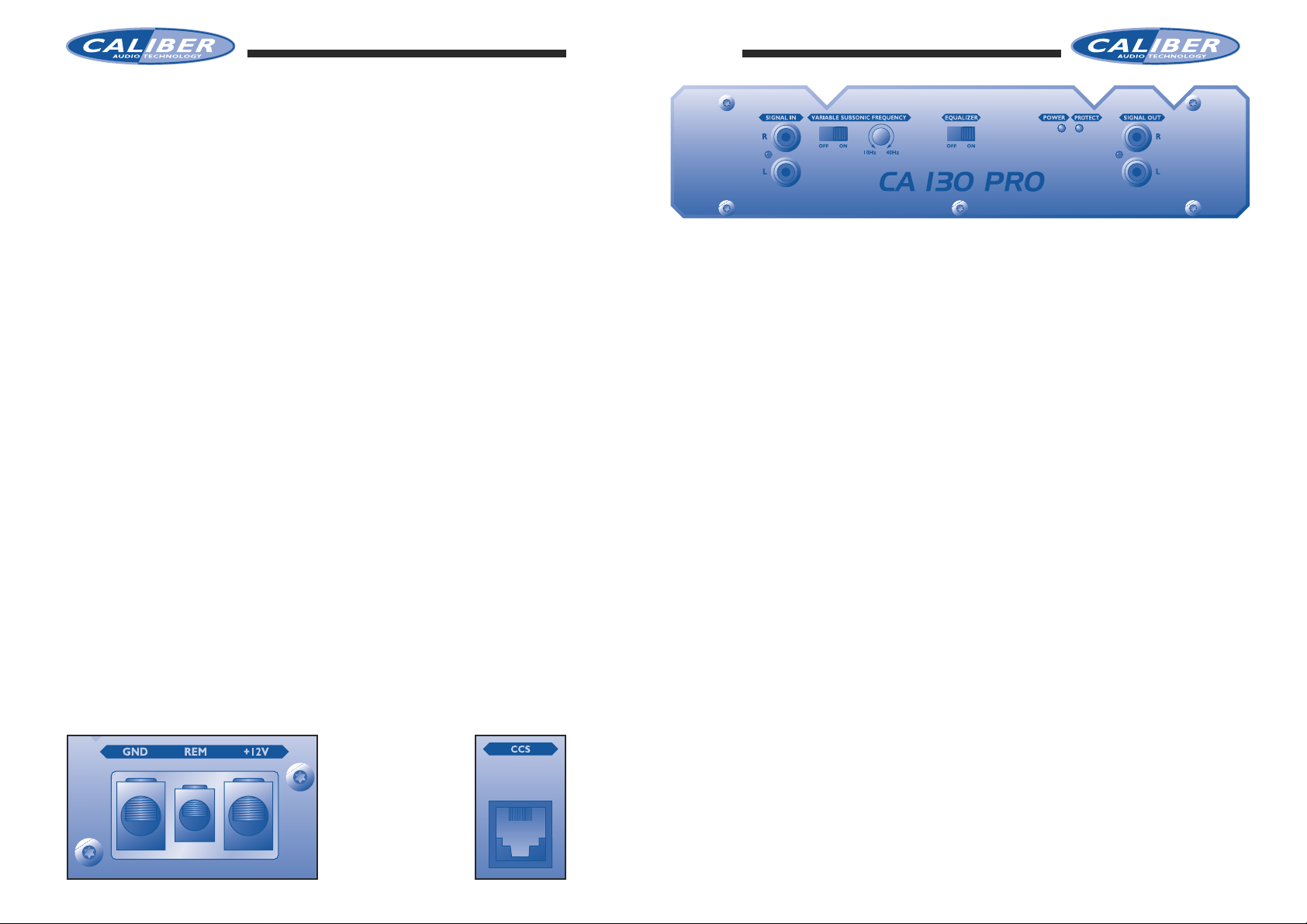
Signal Input
• The RCA’s to your left are the ‘Line-in’ terminals and are to be connected
with your radio/cassett or CD player.Make sure you put the left channel to
the RCA-jack marked “Left”, and the right channel to the RCA-jack marked
“Right”. When you’re the proud owner of a 4 channel amplifier, you have to
pay extra attention.These amplifiers have a 4 channel input. Don’t mix up all
the different channels:Left,Right Front and Rear and connect them with care.
The CA 670 is a 6-channel amplifier which gives you an option to connect an
external signal input, or have the signal input linked internally. You can select
this by the switch right to the subwoofer RCA-input teminals.
• As you can see, each Caliber amplifier offers you the possibility to connect a
second (or more) amplifier(s) to your system via the “Signal-out” terminals
(except CA 670).The advantage of two amplifiers is that one amplifier can be
used for normal stereo,while the other is used as a subwoofer amplifier.
• All Caliber amplifiers have a variable input level adjustment. It allows you to
match any signal source (CD player,AM/FM cassettedeck, etc) correctly from
its pre-amp output into your Caliber amplifier. The adjustment ranges from
15V - 500mV(0.5V).
•For the professionals outthere,Caliber has intergraded a subsonic filter in this
amplifier.This 12dB/Oct. subsonic filter is variable from 10Hz to 40Hz.
Of course you can switch it of,in case you don’t have a need for it.
• The last knob you can switch is the on/off switch for the build in equalizer
which you find on top of your amplifier.
• The Competition Pro amplifiers are all fitted with a CCS entrance.The CCS
is the Caliber Control System,which can be purchased as an option.The CCS
gives you information of how the status of your amplifier is. How many voltage it consumes,what the temperature is and whether it is in a termal or shortcircuit protection.It can give this information simultaniously for up to 4 amplifiers,and always gives you a warning when an amplifier disfunctions.
REMEMBER TO ALWAYS DISCONNECT BATTERY GROUND
BEFORE WORKING ON A VEHICLE’S ELECTRICAL SYSTEM
•We highly recommend that you carefully design your Car Audio System before
you start the installation. Make sure that the cables for power and signal are
not on the same side of the vehicle,and do not cross each other.This will help
reduce any noises caused by the power cable radiating into the signal cables. If
a signal cable is too close to a power cable,it will pick up the magnetic field of
the power cable,which will lead to a loss of quality in the signal.
•Always use the largest gauge power/ground cable available, at least 10 mm2(8
AWG). Ask your local Caliber dealer for the Caliber PowerflowTMpower-,
ground- and remote cables.A guarantee for a safe power management.
•For the protection of your vehicle,always place a fuse or circuit breaker no
more than 30 cm (12”) from the battery.This fuse or circuit breaker should
be greather than the fuse(s) of your amplifier for optimal protection.
For instance: a Caliber Competition Pro Series amplifier has 2x 25A fuses.
Your “vehicle protection” fuse should be about 60A (2x25A=50A).Get good
professional advice about the value of this specific fuse.
REMEMBER TO ALWAYS DISCONNECT BATTERY GROUND
BEFORE WORKING ON A VEHICLE’S ELECTRICAL SYSTEM
Getting your power started
• First,the +12V terminal is connected directly to the battery of your car.Use
a cable of at least 10 mm2 (8 AWG),and make sure that the connectors are of
the same value. Don’t forget the extra “Vehicle protection” fuse.
The 12V + terminal should NOT be connected to the car fuse box.
• Second,the ground terminal (GND) must be fastened secur ely to the chassis of the
vehicle with the same gauge cable as the positiv e cable (the same amount of pow er
has to run through it).Ensure that all paint,undercoating or any other insulation is
removed from the area where you want to make your ground connection to .
• Third, the last cable to connect is your remote turn-on (REM). Many radio-cassette and CD-players have an output terminal for connection of the REM of a
amplifier. If you don’t have such an output,a separate switch must be installed
to control your amplifiers on/off function.
Large Powerterminal
for optimal power
distribution.
CCS entrance
for optional
Caliber Control System
Page 5

Speakeroutput 6-channel amplifiers
• In case you have a Caliber Competition Pro series 4-channel or 6 channel
amplifier you hav e to pa y extra attention to your speak er connections.Be sure
that the front speaker output terminal (left and right) is connected to the
front speakers,the rear speaker output terminal (left and right) is connected
to your rear speakers and your subwoofer(s) to the subwoofer output terminal. (Note: if you only use one subwoofer on amplifier, you are advised to
connect it in a bridged mode. Be sure that in the bridged mode you connect
the Left (+) positive to the positive speaker terminal and the Right (-) negative to the negative speaker terminal.)
• Enjoy your installation and have lots of fun and good music in your moving
sound machine.
Speakeroutput 2-channel amplifiers
Speaker output
• All the Caliber Competition Pro Series amplifiers have a Stereo/Bridgeable TriMode speaker output terminal.The amplifier has its own stereo/bridge switch
built-in,so there is no need to select a stereo or bridged mode.You can connect the speakers to each channel in stereo mode, and simultaneously connect a sub-woofer to the speaker terminal in the bridged mode.
•Pay attention in connecting your speakers and sub-woofer.Be sure to observe
correct speaker output connections and polarity.
In the stereo mode,connect the right speaker output to the right speaker and
the left to the left.
Connect the positive (+) output to the positive (+) speaker terminal and the
negative (-) output to the negative (-) speakerterminal.
• In the bridged mode connect the Left(+) positive to the positive speak er terminal and the Right (-) negative to the negative speaker terminal.
• Do not use the negative speaker output commonly for left and right speakers
(common ground).Improper polarity causes a loss of bass response.
• Use a quality speak er cable f or your Car Audio System.Once you’ve heard the
difference,you’ll know why we advise you to consult y our local Caliber dealer
for our range of stereo loudspeaker cables with gold-plated connectors.
• Never connect the negative speaker output to the chassis of your vehicle.
This can cause severe damage to your Car Audio System.
Speakeroutput 4-channel amplifiers
Page 6

The mono position, if you have connected a subwoofer in a bridged mode.The
phase can now be shifted by turning on the potmeter of the right channel..
Adjusting the phase is not an easy job.You have to listen very carefully to hear
the difference. The best way to do it is to play some music you know very well
and has a lot of vocals in it. When you start adjusting you can hear the vocals
shifting over your front stage .Ask someone to help you with this fine tuning.
In that way you can remain seated in your car and listen to the changes in the
music,while the otherone adjusts the phase by turning slowly on the potmeters.
The phase-shift is variable from 0 to 180 degrees. Allthough your amplifier is
equipped with these phase-shift controls,it is not always necessary to use them.
So if you don’t know if you have a phase problem,or can’t hear the difference if
you are adjusting the phase,leave the phase control untouched and consult y ou r
local Caliber dealer. He is trained for this job,and will be willing to help you.
Variable Crossover
A Caliber Competition Pro amplifier has a variable
crossover for each pair of channels. It can be
switched into FullRange (Off-position), LowPass
(put it on the LPF-position in the middle) or to
HighPass (in which case you hav e to slide it all the
way to the left in the HPF-position).
Once you have selected the position in which you want that pair of channels to
play,you can start adjusting the filterfrequency by turning on the frequency potmeter.The filterfrequency is variable betw een 50Hz and 250Hz.You get the best
result if you play several parts of music you know very well,whenyou are adjusting your filter.Always adjust every pair of speakers separately. You can turn of
your other pair(s) of speakers and/or your sub’s, by simply disconnecting the
input RCA’s for these channels.In this way you will be able to hear every reacting this speakerpair gives you when you are adjusting them. Do the same thing
if you want to adjust your subwoofers. Let the sub’s play alone, and listen carefully to the reactions to the music.
Golden Rule
It is lots of fun to adjust your amplifier,but you can easily ov er do it.There is one
golden rule you hav e to remember:Before you start tuning your amplifier,always
turn the input level all the way down to a minimum (15V).Then you can safely
adjust all the options your amplifier offers you. Once you have fine tuned the
sound to your likings, you can slowly turn your input level up a bit, untill you
hear your amplifier starting to clip (or look at the clipping LED’s). Once your
amplifiers clips,you have given it to much input level,so you will have to turn it
down a little. In this way you will get the maximum power from your amplifier,
without the danger of damaging your speakers or subwoofers.
On top of your Competition Pro Series amplifier you will find the build-in topcontrols.The 2-channel amplifiers have one set of controls for right/left.The 4channel amplifiers have two sets of controls, one for front left/right and one for
rear left/right, The 6-channel amplifiers have 3 sets of controls, one for front
left/right,one for rear left/right and one for the subwoofer channel.
Equalizer
These topcontrols have a 7-band equalizer for each channel (exept the subwoofer
channels on the 6-channel amplifier). Normal equalizers adjust the sound for
both the right and the left channel.By separating the equalizers for the left and
right channel you are able to adjust the sound in your car ver y precisely.Since,
in a car, you are sitting at the driversseat you don’t hear the same sound from
your right speakers,as you do from your left speakers (One side is further away
from you, while the other side is positioned differently to your ears, so every
side gives you a different sound). By adjusting the right- and the left channel
separately you can make them sound the same.
All the 7 frequences we selected for y ou on this equalizer are the ones that ha v e
the most influence on the total audio spectrum.
Level Control
Before adjusting the equalizer, make sure that your input level is set
to a minimum (Note:the minimum is 15V,not 0,5V).
Every input level control controls a pair of channels (left and right)
per control unit.So for 4- channel amplifiers turn down two level controls (front and rear).For 6-channel amplifiers you even have to turn
down 3 level controls (front, rear and subwoofer). In this way you will have
enough headroom to adjust your equalizer correctly,without your outputsignal
starting to clip before the adjustment is finished.
Variable phase control.
Each pair of channels (left/right, front/rear and subwoofer) has a variable phase
control,for eliminating every eventual phase problem
that will occur. Phase problems can occur for
various reasons;the use of passive filters,the difference in path length,unwanted reflections or others.
The phase control switch has three positions. The
off position for if you do not need to use the phase control.The stereo position,
if you have connected both right and left speakers, you can shift the fase separately
for the left or right channel by turning the potmeters.
•
•
50Hz 250Hz 1kHz 2.5kHz 5kHz 7.5kHz 10kHz
•
•
•
•
•
•
•
•
•
•
•
•
•
•
•
•
•
•
•
LEVEL
15V
0.5V
FREQUENCY
•
••
50Hz
250Hz
VARIABLE CROSSOVER
CLIPPING
HPF LPF OFF
VARIABLE PHASE CONTROL
MONO OFF
RIGHT/
LEFT STEREO
MONO
Page 7

Nous vous remercions d’avoir porté votre choix sur un produit Caliber. Vous
manifestez ainsi votre souhait de bénéficier de la technologie Car Audio la plus
évoluée.Caliber ne recule devant aucun effort pour vous proposer les meilleurs
produits et recherche sans cesse à satisfaire davantage encore ses clients.
Correctement installé,votre amplificateur Caliber reproduira pendant de longues
années un son d’une qualité parfaite.Au préalable, lisez attentivement ce manuel
afin de protéger votre véhicule et de profiter au mieux des performances de
votre installation Car Audio.
Garantie Caliber
Vu la complexité de nos produits,nous vous conseillons vivement de confier l’installation de cet amplificateur à un revendeur agréé Caliber.Votre appareil bénéficiera ainsi d’une garantie de 12 mois à partir de la date d’achat. Si vous installez vous-même l’amplificateur, nous vous souhaitons de mener à bien cette
tâche. En suivant nos recommandations,vous ne devriez guère éprouver de difficultés. Toutefois, notre garantie est alors limitée à 30 jours à partir de la date
d’achat.
Accessoires Caliber
Pour permettre à cet amplificateur d’atteindre le niveau de performances
exceptionnel dont il est capable,il est nécessaire que les sources d’alimentation,
les sources des signaux,les haut-parleurs et les raccordements soient d’une parfaite qualité.N’oubliez pas que Caliber n’est pas simplement un fabricant d’amplificateurs. Nous produisons également tout ce dont vous avez besoin pour
réaliser un système Car Audio “optimal” (à l’exception du véhicule !). N’oubliez
donc pas de choisir du matériel Caliber pour tous vos raccordements et renseignez-vous sur notre gamme d’accessoires auprès de v otre revendeur Caliber.
Table des matières
Avant de commencer l’installation . . . . . . . . . . . . . . . . . . . . . . . . . . . . . . . . 13
Particularités et caractéristiques . . . . . . . . . . . . . . . . . . . . . . . . . . . . . . . . . 14
Montage et emplacements . . . . . . . . . . . . . . . . . . . . . . . . . . . . . . . . . . . . . . 17
Installation de l’amplificateur . . . . . . . . . . . . . . . . . . . . . . . . . . . . . . . . . . . . 18
Réglages . . . . . . . . . . . . . . . . . . . . . . . . . . . . . . . . . . . . . . . . . . . . . . . . . . . . 22
. . . . . . . . . . . . . . . . . . . . . . . . . . . . . . . . . . . . . . . . . . . . . . . . . . . . . . . . . . . . . . . . . . . . . . . . . . . . . . . . . . . . . . . . . . . . . . . . . . . . . . . . . . . . . . . . . . . . . . . . .
. . . . . . . . . . . . . . . . . . . . . . . . . . . . . . . . . . . . . . . . . . . . . . . . . . . . . . . . . . . . . . . . . . . . . . . . . . . . . . . . . . . . . . . . . . . . . . . . . . . . . . . . . . . . . . . . . . . . . . . . .
. . . . . . . . . . . . . . . . . . . . . . . . . . . . . . . . . . . . . . . . . . . . . . . . . . . . . . . . . . . . . . . . . . . . . . . . . . . . . . . . . . . . . . . . . . . . . . . . . . . . . . . . . . . . . . . . . . . . . . . . .
. . . . . . . . . . . . . . . . . . . . . . . . . . . . . . . . . . . . . . . . . . . . . . . . . . . . . . . . . . . . . . . . . . . . . . . . . . . . . . . . . . . . . . . . . . . . . . . . . . . . . . . . . . . . . . . . . . . . . . . . .
. . . . . . . . . . . . . . . . . . . . . . . . . . . . . . . . . . . . . . . . . . . . . . . . . . . . . . . . . . . . . . . . . . . . . . . . . . . . . . . . . . . . . . . . . . . . . . . . . . . . . . . . . . . . . . . . . . . . . . . . .
. . . . . . . . . . . . . . . . . . . . . . . . . . . . . . . . . . . . . . . . . . . . . . . . . . . . . . . . . . . . . . . . . . . . . . . . . . . . . . . . . . . . . . . . . . . . . . . . . . . . . . . . . . . . . . . . . . . . . . . . .
. . . . . . . . . . . . . . . . . . . . . . . . . . . . . . . . . . . . . . . . . . . . . . . . . . . . . . . . . . . . . . . . . . . . . . . . . . . . . . . . . . . . . . . . . . . . . . . . . . . . . . . . . . . . . . . . . . . . . . . . .
. . . . . . . . . . . . . . . . . . . . . . . . . . . . . . . . . . . . . . . . . . . . . . . . . . . . . . . . . . . . . . . . . . . . . . . . . . . . . . . . . . . . . . . . . . . . . . . . . . . . . . . . . . . . . . . . . . . . . . . . .
. . . . . . . . . . . . . . . . . . . . . . . . . . . . . . . . . . . . . . . . . . . . . . . . . . . . . . . . . . . . . . . . . . . . . . . . . . . . . . . . . . . . . . . . . . . . . . . . . . . . . . . . . . . . . . . . . . . . . . . . .
. . . . . . . . . . . . . . . . . . . . . . . . . . . . . . . . . . . . . . . . . . . . . . . . . . . . . . . . . . . . . . . . . . . . . . . . . . . . . . . . . . . . . . . . . . . . . . . . . . . . . . . . . . . . . . . . . . . . . . . . .
. . . . . . . . . . . . . . . . . . . . . . . . . . . . . . . . . . . . . . . . . . . . . . . . . . . . . . . . . . . . . . . . . . . . . . . . . . . . . . . . . . . . . . . . . . . . . . . . . . . . . . . . . . . . . . . . . . . . . . . . .
. . . . . . . . . . . . . . . . . . . . . . . . . . . . . . . . . . . . . . . . . . . . . . . . . . . . . . . . . . . . . . . . . . . . . . . . . . . . . . . . . . . . . . . . . . . . . . . . . . . . . . . . . . . . . . . . . . . . . . . . .
. . . . . . . . . . . . . . . . . . . . . . . . . . . . . . . . . . . . . . . . . . . . . . . . . . . . . . . . . . . . . . . . . . . . . . . . . . . . . . . . . . . . . . . . . . . . . . . . . . . . . . . . . . . . . . . . . . . . . . . . .
. . . . . . . . . . . . . . . . . . . . . . . . . . . . . . . . . . . . . . . . . . . . . . . . . . . . . . . . . . . . . . . . . . . . . . . . . . . . . . . . . . . . . . . . . . . . . . . . . . . . . . . . . . . . . . . . . . . . . . . . .
. . . . . . . . . . . . . . . . . . . . . . . . . . . . . . . . . . . . . . . . . . . . . . . . . . . . . . . . . . . . . . . . . . . . . . . . . . . . . . . . . . . . . . . . . . . . . . . . . . . . . . . . . . . . . . . . . . . . . . . . .
. . . . . . . . . . . . . . . . . . . . . . . . . . . . . . . . . . . . . . . . . . . . . . . . . . . . . . . . . . . . . . . . . . . . . . . . . . . . . . . . . . . . . . . . . . . . . . . . . . . . . . . . . . . . . . . . . . . . . . . . .
. . . . . . . . . . . . . . . . . . . . . . . . . . . . . . . . . . . . . . . . . . . . . . . . . . . . . . . . . . . . . . . . . . . . . . . . . . . . . . . . . . . . . . . . . . . . . . . . . . . . . . . . . . . . . . . . . . . . . . . . .
. . . . . . . . . . . . . . . . . . . . . . . . . . . . . . . . . . . . . . . . . . . . . . . . . . . . . . . . . . . . . . . . . . . . . . . . . . . . . . . . . . . . . . . . . . . . . . . . . . . . . . . . . . . . . . . . . . . . . . . . .
. . . . . . . . . . . . . . . . . . . . . . . . . . . . . . . . . . . . . . . . . . . . . . . . . . . . . . . . . . . . . . . . . . . . . . . . . . . . . . . . . . . . . . . . . . . . . . . . . . . . . . . . . . . . . . . . . . . . . . . . .
. . . . . . . . . . . . . . . . . . . . . . . . . . . . . . . . . . . . . . . . . . . . . . . . . . . . . . . . . . . . . . . . . . . . . . . . . . . . . . . . . . . . . . . . . . . . . . . . . . . . . . . . . . . . . . . . . . . . . . . . .
. . . . . . . . . . . . . . . . . . . . . . . . . . . . . . . . . . . . . . . . . . . . . . . . . . . . . . . . . . . . . . . . . . . . . . . . . . . . . . . . . . . . . . . . . . . . . . . . . . . . . . . . . . . . . . . . . . . . . . . . .
. . . . . . . . . . . . . . . . . . . . . . . . . . . . . . . . . . . . . . . . . . . . . . . . . . . . . . . . . . . . . . . . . . . . . . . . . . . . . . . . . . . . . . . . . . . . . . . . . . . . . . . . . . . . . . . . . . . . . . . . .
. . . . . . . . . . . . . . . . . . . . . . . . . . . . . . . . . . . . . . . . . . . . . . . . . . . . . . . . . . . . . . . . . . . . . . . . . . . . . . . . . . . . . . . . . . . . . . . . . . . . . . . . . . . . . . . . . . . . . . . . .
. . . . . . . . . . . . . . . . . . . . . . . . . . . . . . . . . . . . . . . . . . . . . . . . . . . . . . . . . . . . . . . . . . . . . . . . . . . . . . . . . . . . . . . . . . . . . . . . . . . . . . . . . . . . . . . . . . . . . . . . .
. . . . . . . . . . . . . . . . . . . . . . . . . . . . . . . . . . . . . . . . . . . . . . . . . . . . . . . . . . . . . . . . . . . . . . . . . . . . . . . . . . . . . . . . . . . . . . . . . . . . . . . . . . . . . . . . . . . . . . . . .
Page 8

Fruits de nos efforts incessants d’innovation et d’amélioration de nos amplificateurs,cette nouvelle génération d’amplificateurs Caliber Competition Pro Series
présente les particularités suivantes:
• Sorties pontables.
• Triple mode de sortie:sortie simultanée en stéréo et en mono
pontée.
• Alimentation MOSFET à découpage à modulation de largeur
d’impulsions (PWM).
• Stable 2 Ohms (ponté mono 4 Ohms)
• Plaquette époxy double face
• Sensibilité d’entrée variable de 15V à 0,5V
• Protection thermique,contre les surcharges et contre les
courts-circuits.
• Excellent circuit de silencieux éliminant tout bruit de commutation.
• Réglage de phase intégré pour chaque canal.
• Égalisateur à 7 bandes intégré pour chaque canal.
• Filtre(s) passe-haut/passe-bas/pleine gamme réglable(s) intégré(s).
• Entrées differentielles à shunter les bruits d’entrée.
• Prises Cinch de sortie du signal pour amplificateur(s) supplémentaire(s) (à l'exception du CA 670).
• Connecteurs d’alimentation surdimensionnés pour une répartition optimale de la puissance.
• Connecteurs pour haut-parleurs plaqués chrome pour un signal
de sortie optimal.
• Conçu et fabriqué en Europe.
• Performances sonores exceptionnelles à la hauteur de vos
exigences.
• Un plaisir d’écoute qui demeure intact au fil des ans.
Tous les amplificateurs Competition Pro Series de Caliber présentent les caractéristiques suivantes,qui sont suivies des caractéristiques propres à chaque modèle.
Réponse en fréquence (+0, -1dB) 20Hz - 30kHz
Distorsion harmonique totale <0,05% avec filtr e pass-bass 80kHz
Rapport signal/bruit (pondération A) >95dB
Sensibilité d’entrée 15V - 500mV
Impédance d’entrée 20kOhm
Coefficient d’amortissement > 180
Impédance de sortie 2 - 8 Ohm
Amplificateurs à 2 canaux
Competition CA 130 Pro Series
Puissance de sortie maximale à 14,4 V
4 Ohm 20Hz - 30kHz THD 1% 2x 130W
4 Ohm 1kHz Mono Pontée 1x 260W
Puissance de sortie continue à 14,4 V
4 Ohm 20Hz - 30kHz THD1% 2x 65W
4 Ohm 1kHz Mono Pontée 1x 130W
Intensité nominale du fusible 20A
Dimensions (L x H x P mm) 200 x 60 x 235
Competition CA 190 Pro Series
Puissance de sortie maximale à 14,4 V
4 Ohm 20Hz - 30kHz THD 1% 2x 190W
4 Ohm 1kHz Mono Pontée 1x 380W
Puissance de sortie continue à 14,4 V
4 Ohm 20Hz - 30kHz THD1% 2x 95W
4 Ohm 1kHz Mono Pontée 1x 190W
Intensité nominale du fusible 25A
Dimensions (L x H x P mm) 250 x 60 x 235
Competition CA 250 Pro Series
Puissance de sortie maximale à 14,4 V
4 Ohm 20Hz - 30kHz THD 1% 2x 250W
4 Ohm 1kHz Mono Pontée 1x 730W
Puissance de sortie continue à 14,4 V
4 Ohm 20Hz - 30kHz THD1% 2x 125W
4 Ohm 1kHz Mono Pontée 1x 250W
Intensité nominale du fusible 2x 20A
Dimensions (L x H x P mm) 320 x 60 x 235
Page 9

Competition CA 510 Pro Series
Puissance de sortie maximale à 14,4 V
4 Ohm 20Hz - 30kHz THD 1% 2x 510W
4 Ohm 1kHz Mono Pontée 1x 1100W
Puissance de sortie continue à 14,4 V
4 Ohm 20Hz - 30kHz THD1% 2x 255W
4 Ohm 1kHz Mono Pontée 1x 510W
Intensité nominale du fusible 4x 20A
Dimensions (L x H x P mm) 440 x 60 x 235
Amplificateurs à 4 canaux
Competition CA 470 Pro Series
Puissance de sortie maximale à 14,4 V
4 Ohm 20Hz - 30kHz THD 1% 4x 130W
4 Ohm 1kHz Mono Pontée 2x 260W
Puissance de sortie continue à 14,4 V
4 Ohm 20Hz - 30kHz THD1% 4x 65W
4 Ohm 1kHz Mono Pontée 2x 130W
Intensité nominale du fusible 40A
Dimensions (L x H x P mm) 330 x 60 x 235
Amplificateur à 6 canaux
Competition CA 670 Pro Series
Puissance de sortie maximale à 14,4 V
4 Ohm 20Hz - 30kHz THD 1% 4x 90W+ 2x 130W
4 Ohm 1kHz Mono Pontée 2x 180W+ 1x 260W
Puissance de sortie continue à 14,4 V
4 Ohm 20Hz - 30kHz THD1% 4x 45W + 2x 65W
4 Ohm 1kHz Mono Pontée 2x 90W+ 1x 130W
Intensité nominale du fusible 25A + 20A
Dimensions (L x H x P mm) 400 x 60 x 235
Montage de l’amplificateur Caliber
Avant de monter votre amplificateur Caliber,vous devez choisir soigneusement
l’emplacement où vous allez l’installer.Vous devez prévoir un espace de ventilation
d’au moins 5cm sur tous les côtés de l’amplificateur afin de permettre l’élimination de la chaleur dégagée par celui-ci. Veillez également à ce que les câbles
d’alimentation et les câbles des signaux puissent être raccordés ou quitter l’amplificateur en ligne droite,afin d’éviter tout risque de mauvais fonctionnement.
L’amplificateur doit être maintenu à l’abri de l’humidité et des rayons directs du
soleil.Il est donc préférable de l’installer dans un des endroits suivants:
• Sur le plancher du coffre.
• Sous le siège du conducteur
• Sur le coffret du subwoofer.
Dès que vous avez choisi l’emplacement adéquat et que vous avez vérifié si l’amplificateur Caliber sera bien ventilé et protégé contre les risques éventuels, marquez la
surface de montage en utilisant l’amplificateur comme gabarit.(Pour que les marques
soient mieux visibles,recouvrez d’abord de bande masquante la surface de montage.)
Percez des trous de 2,5 mm de section aux emplacements marqués et fixez l’amplificateur à l’aide des vis autotaraudeuses fournies d’origine.
Remarque : Ne percez jamais aucun trou en utilisant l’amplificateur
comme gabarit. Vous risqueriez en effet d’endommager
son revêtement anodisée.
Page 10

DEBRANCHEZ TOUJOURS LA MASSE DE LA BATTERIE AVANT
D’INTERVENIR SUR LE SYSTEME ELECTRIQUE D’UN VEHICULE
• Nous vous conseillons de constituer soigneusement votre installation Car Audio avant de
procéder à son installation.Assurez-vous que les câbles d’alimentation et les câbles des signaux ne se trouvent pas du même côté du véhicule et qu’ils ne se croisent pas.Cela vous
permettra de réduire les bruits engendrés par le rayonnement des câbles d’alimentation
dans les câbles de signaux.Si un câble de signal est trop proche d’un câble d’alimentation,
il captera son champ magnétique et cela entraînera une perte de qualité du signal.
• Choisissez toujours le câble d’alimentation/câble de masse qui présente la section la
plus importante disponible, soit au moins 10 mm
2
(8 AWG).Demandez à votre revendeur Caliber d’équiper votre installation de câbles d’alimentation,de câbles de masse
et de câbles de commande à distance Caliber Powerflow™.Vous aurez ainsi l’assurance de disposer d’un circuit d’alimentation particulièrement sûr.
• Pour protéger votr e véhicule,placez toujours un fusible ou un coupe-circuit à 30 cm (12”)
maximum de la batterie. Pour une protection optimale, ce fusible ou ce coupe-circuit
doit avoir une intensité supérieure à celle du ou des fusibles de votre amplificateur.Par
exemple:un amplificateur Caliber Competition Pro Series possède 2 fusibles de 25A.Le
fusible de "protection du véhicule" doit avoir une intensité d'environ 60A (2x25A=50A).
Demandez conseil à un professionnel pour déterminer l'intensité exacte de ce fusible.
Raccordement de l’alimentation
•Premièrement, la borne +12V doit être raccordée directement à la batterie du véhicule.
Utilisez un câble présentant une section d’au moins 10 mm
2
(8 AWG) et assurez-v ous que
les connecteurs sont de même valeur.N’oubliez pas le fusible supplémentaire de “protection
du véhicule”.La borne 12V + ne doit PAS être raccordée à la boîte à fusibles du véhicule.
• Deuxièmement, la borne de masse (GND) doit être solidement fixée au châssis du
véhicule en utilisant du câble de même section que le câble positif (étant donné qu’il
doit acheminer du courant de même intensité). Assurez-vous que l’endroit où vous
effectuez le raccordement de la masse est exempt de peinture,de revêtement de protection ou de toute autre forme d’isolant.
•Troisièmement,vous devez terminer par le raccordement du câble de commande à distance(REM).De nombreux lecteurs CD et autoradios avec lecteurs de cassette possèdent une borne de sortie destinée au raccordement de la commande à distance d’un
amplificateur. Si votre appareil n’est pas équipé d’une telle sortie, vous devez installer
un commutateur distinct qui commandera la marche/arrêt de vos amplificateurs.
Entrée du Signal
• Les prises Cinch situées sur votre gauche constituent les bornes d'entrée ligne et sont
raccordées à votre radiocassette ou à votre lecteur de CD.Vérifiez si le canal gauche est
bien raccordé à la prise Cinch qui porte l'indication "Left" et le canal droit à la prise Cinch
qui porte l'indication "Right". Si vous êtes l'heureux propriétaire d'un amplificateur à 4
canaux,vous devez être encore plus attentif. Ces amplificateurs possèdent une entrée 4
canaux. Ne mélangez pas tous les canaux (gauche, droit,avant et arrière) et soyez très
vigilant au moment de leur raccordement.Le CA 670 est un amplificateur à 6 canaux qui
accepte une entrée de signal externe ou le raccordement du signal d'entrée en interne.
Vous pouvez choisir l'entrée de signal souhaitée à l'aide du commutateur situé à droite
des bornes d'entrée Cinch pour subwoofer.
• Comme vous pouvez le constater, chaque amplificateur Caliber vous offre la possibilité
de raccorder un deuxième amplificateur (ou davantage) à votre système par l'intermédiaire des bornes "Signal-out" (à l'exception du CA 670).Une installation à deux amplificateurs présente un avantage substantiel,puisqu'un amplificateur peut être utilisé pour le
son stéréo normal et l'autre comme amplificateur pour subwoofer.
•Tous les amplificateurs Caliber possèdent un réglage du niveau d'entrée variable. Vous
pouvez ainsi régler correctement sur votre amplificateur Caliber le signal provenant de
la sortie préamplificateur de la source, qu'il s'agisse d'un lecteur de CD,d'un autoradio
AM/FM,d'une platine à cassette, etc.La plage de réglage est comprise entre 15V - 500mV
(0,5V).
•A l'intention des professionnels,Caliber a intégré un filtre subsonique à cet amplificateur.
Ce filtre subsonique de 12dB/Oct.est réglable entre 10Hz et 40Hz.
Bien entendu,vous pouvez le désactiver si vous n'en avez pas besoin.
• Le dernier commutateur sur lequel vous pouvez agir est l'interrupteur marche/arrêt de
l'égaliseur intégré,que vous trouverez sur le dessus de l'amplificateur.
• Les amplificateurs Competition Pro sont tous équipés d'une entrée CCS.Le CCS n'est
autre que le système de commande Caliber qui peut être acheté en option.Le CCS vous
renseigne sur l'état de votre amplificateur, notamment sa consommation électrique, sa
température ainsi que l'état de sa protection thermique et de sa protection contre les
courts-circuits.Le CCS peut fournir des informations simultanées sur 4 amplificateurs et
vous aver tit toujours en cas de défaillance de l'un d'entre eux.
Borne de puissance
surdimensionnée pour une
répartition optimale de la
puissance.
Entrée CCS pour
système de commande
Caliber en option
Page 11

Sortie haut-parleurs Amplificateurs à 6 canaux
• Si vous possédez un amplificateur Caliber Competition Pro à 4 ou 6 canaux,vous devez
être particulièrement attentif au raccordement des haut-parleurs. Assurez-vous que la
borne de sortie haut-parleurs avant (gauche et droit) est raccordée aux haut-parleurs
avant, que la borne de sortie haut-parleurs arrière (gauche et droit) est raccordée aux
haut-parleurs arrière, et que le ou les subwoofers sont raccordés à la borne de sortie
subwoofers. (Remarque : Si vous ne raccordez qu'un seul subwoofer à l'amplificateur, il
est préférable de le connecter en mode ponté. Dans ce mode, veillez à raccorder la
borne positive (+) gauche à la borne pour haut-parleurs positive et la borne négative (-)
droite à la borne pour haut-parleurs négative.)
Sortie haut-parleurs Amplificateurs à 2 canaux
Sortie haut-parleur s
•Tous les amplificateurs Caliber Competition Pro Series possèdent une borne de sortie
haut-parleurs tri-mode stéréo/pontable.L'amplificateur intègre son propre commutateur
stéréo/pont et il est donc inutile de sélectionner le mode stéréo ou le mode ponté.
Vous pouvez raccorder les haut-parleurs à chaque canal en mode stéréo et raccorder
simultanément un subwoofer à la borne haut-parleurs en mode ponté.
•Soyez par ticulièrement attentif au raccordement des haut-parleurs et du subwoofer.
Respectez scrupuleusement la polarité et les connexions de la sortie haut-parleurs.
En mode stéréo, raccordez la sortie haut-parleurs droite au haut-parleur droit et la
sortie haut-parleurs gauche au haut-parleur gauche.
Raccordez la sortie positive (+) à la borne pour haut-parleurs positive (+),et la sortie
négative (-) à la borne pour haut-parleurs négative (-).
• En mode ponté,raccordez la borne positive (+) gaucheà la borne pour haut-parleurs
positive et la borne négative (-) droite à la borne pour haut-parleurs négative.
• N'utilisez pas la sortie haut-parleurs négative à la fois pour le haut-parleur gauche et
le haut-parleur droit (masse commune). Toute erreur de polarité peut entraîner une
diminution de la réponse en graves.
• Utilisez un câble pour haut-parleurs de qualité pour votre installation audio .Il vous suffira d'entendre la différence pour comprendre la raison pour laquelle nous vous conseillons de vous adresser à votre revendeur Caliber qui vous montrera notre gamme
de câbles pour haut-parleurs stéréo équipés de connecteurs plaqués or.
• Ne raccordez jamais la sortie haut-parleurs négative au châssis du véhicule.
Cela risquerait d'endommager gravement votre installation audio.
Sortie haut-parleurs Amplificateurs à 4 canaux
Page 12

Sur le dessus de votre amplificateur Competition Pro Series,vous trouverez les
commandes intégrées. Il existe un jeu de commandes pour les canaux
droit/gauche sur les amplificateurs à 2 canaux.Sur les amplificateurs à 4 canaux,
vous remarquerez deux jeux de commandes, un pour les canaux gauche/droit
avant et un pour les canaux gauche/droit arrière. Les amplificateurs à 6 canaux
sont équipés de trois jeux de commandes, un pour les canaux gauche/droit
avant,un pour les canaux gauche/droit arrière et un pour le canal subwoofer.
Egaliseur
Ces commandes comprennent un égaliseur à 7 bandes pour chaque canal (à
l'exception des canaux pour subwoofer de l'amplificateur à 6 canaux).Les égaliseurs ordinaires règlent le son des canaux gauche et droit.En séparant l'égaliseur du canal gauche de celui du canal droit,vous pouvez régler le son de manière très précise.Assis dans le siège du conducteur,vous ne percev ez pas le même
son des haut-parleurs droit et des haut-parleurs gauche.(Comme vous êtes proche d'un côté et éloigné de l'autre, vos deux oreilles ne perçoivent pas les
mêmes sons.) En réglant séparément les canaux gauche et droit,vous pouvez harmoniser leur son.
Les 7 fréquences que nous avons sélectionnées pour cet égaliseur sont celles qui
exercent le plus d'influence sur l'ensemble du spectre auditif.
Commande de niveau
Avant de régler l'égaliseur, assurez-vous que le niveau d'entrée est
réglé au minimum.(Remarque: le minimum est de 15V et non de 0,5V.)
Chaque commande de niveau d'entrée contrôle une paire de canaux
(gauche et droit) par unité de commande.Ainsi, pour les amplificateurs à 4 canaux, coupez deux commandes de niveau (avant et arrière).Dans le cas des amplificateurs à 6 canaux,vous pouvez même couper 3 commandes de niveau (avant,arrière et subwoofer).Vous disposez ainsi d'une extension suffisante de la bande passante pour régler correctement votre égaliseur,tout
en écartant le risque d'écrêtage du signal de sortie avant que le réglage soit terminé.
Commande de phase variable
Chaque paire de canaux (gauche/droit,avant/ arrière et subwoofer) possède une commande de phase
variable qui permet d'éliminer tout problème de
phase éventuel.
Les problèmes de phase peuvent survenir pour diverses raisons, que ce soit
l'utilisation de filtres passifs, la différence de longueur de trajet, les réflexions
indésirables,etc.
Le sélecteur de commande de phase possède trois positions. Réglez-le sur la
position Off si vous n'avez pas besoin de la commande de phase . Choisissez la
position Stéréo si vous avez connecté des haut-parleurs gauche et droit, afin de
pouvoir régler séparément la phase du canal gauche et,celle du canal droit à l'aide
des potentiomètres.
Optez pour la position Mono si vous av ez raccor dé un subw oofer en mode ponté.
La phase peut maintenant être réglée en tournant le potentiomètre du canal droit.
Régler la phase n'est pas aisé.Vous devez écouter attentivement pour percevoir
la différence. La meilleure manière de procéder consiste à écouter un enregistrement musical qui comporte de nombreux passages chantés et qui vous est
familier.Lorsque vous procédez au réglage,vous entendez véritablement les voix
se déplacer entre les canaux avant. Pour un réglage précis, n'hésitez pas à
demander l'aide d'une tierce personne.
Vous pouvez ainsi rester assis dans votre voiture, laisser cette personne régler
la phase en tournant lentement les potentiomètres,et écouter leur effet sur la
musique.
Le changement de phase peut être réglé entre 0 et 180 degrés.Bien que votre
amplificateur soit équipé de ces commandes de changement de phase, il n'est
pas toujours nécessaire de les utiliser.Si vous n'êtes pas certain de connaître un
problème de phase,ou si vous ne percevez pas de différence lorsque vous réglez la phase, ne modifiez pas la position de la commande de phase et consultez
votre revendeur Caliber. Il pourra vous aider, car il possède la formation requise.
Filtre d'aiguillage variable
Un amplificateur Caliber Competition Pro possède un filtre d'aiguillage variable
pour chaque paire de canaux. Il peut être réglé sur la position Pleine gamme
(position Off),Passe-bas (position LPF au centre) ou Passe-haut (position HPF à
l'extrême gauche).
Lorsque vous av ez sélectionné la position souhaitée pour cette paire de canaux,
vous pouvez commencer à régler la fréquence du filtre en tournant le potentiomètre de fréquence.La fréquence du filtre peut être réglée entre 50Hz et 250Hz.
Vous obtiendrez un résultat optimal si vous écoutez plusieurs morceaux de musique
que vous connaissez bien, pendant que vous réglez
le filtre.
•
•
50Hz 250Hz 1kHz 2.5kHz 5kHz 7.5kHz 10kHz
•
•
•
•
•
•
•
•
•
•
•
•
•
•
•
•
•
•
•
LEVEL
15V
0.5V
VARIABLE PHASE CONTROL
MONO OFF
RIGHT/
LEFT STEREO
MONO
FREQUENCY
•
••
50Hz
250Hz
VARIABLE CROSSOVER
CLIPPING
HPF LPF OFF
Page 13

Wir danken Ihnen, daß Sie sich für ein Caliber-Produkt entschieden haben. Mit diesem
Kauf haben sie sich zum höchsten Qualitätsmaßstab in der Car-HiFi-Technik bekannt.
Caliber möchte Ihnen ein optimales Produkt bieten und bemüht sich konsequent, die
Zufriedenheit seiner Kunden stetig zu steigern.
Ihr Caliber-Verstärker wird Ihnen den sachgemäßen Einbau durch jahrelange hochwertige
Wiedergabe danken.Bevor Sie das Gerät in Ihrem Fahrzeug montieren,lesen Sie jedoch
bitte diese Bedienungsanleitung sorgfältig und vollständig durch,um Schäden am Fahrzeug
zu vermeiden und eine optimale Leistung Ihrer Audio-Anlage zu erzielen.
Caliber-Gewährleistung
Bei unseren Produkten handelt es sich um komplizierte technische Systeme.Wir empfehlen
daher nachdrücklich, den Einbau dieses Verstärkers durch eine Caliber-Vertrags-werkstatt
vornehmen zu lassen. Bei sachgemäßem Einbau durch die Fachwerkstatt gewähren wir
eine Garantie von 12 Monaten ab dem Kaufdatum.
Falls Sie das Gerät lieber selbst montieren möchten,wünschen wir Ihnen dabei viel Spaß
und Erfolg.Um optimale Ergebnisse zu erzielen,befolgen Sie bitte unbedingt die in dieser
Anleitung enthaltenen Hinweise. Wir können in diesem Fall allerdings nur eine eingeschränkte Gewährleistung von 30 Tagen ab dem Kaufdatum übernehmen.
Caliber-Zubehör
Damit dieser Verstärker seine hervorragende Leistung voll entwickeln kann, müssen
Spannungsversorgung, Signalquellen, Lautsprecher und Verbindungstechnik von höchster
Qualität sein.In diesem Zusammenhang erlauben wir uns den Hinweis, daß Caliber nicht
nur Verstärker herstellt. Unser Produktprogramm umfaßt sämtliche Komponenten, die
Sie für eine optimale Car-HiFi-Anlage benötigen, d.h. alle Teile, die nicht zum Auto selbst
gehören. Verwenden Sie daher auch zum Anschluß des Geräts nach Möglichkeit nur
Caliber-Originalteile und fragen Sie Ihren örtlichen Caliber-Vertragshänder nach unserem
Zubehörprogramm.
Inhaltsverzeichnis
Vor dem Einbau . . . . . . . . . . . . . . . . . . . . . . . . . . . . . . . . . . . . . . . . . . . . . . . . . . . . . 25
Leistungsmerkmale . . . . . . . . . . . . . . . . . . . . . . . . . . . . . . . . . . . . . . . . . . . . . . . . . . .26
Technische Daten . . . . . . . . . . . . . . . . . . . . . . . . . . . . . . . . . . . . . . . . . . . . . . . . . . . 27
Montage und Einbauorte . . . . . . . . . . . . . . . . . . . . . . . . . . . . . . . . . . . . . . . . . . . . . . 29
Elektrische Anschlüsse . . . . . . . . . . . . . . . . . . . . . . . . . . . . . . . . . . . . . . . . . . . . . . . . 30
Signal Anschlüsse . . . . . . . . . . . . . . . . . . . . . . . . . . . . . . . . . . . . . . . . . . . . . . . . . . . . 31
Lautsprecher Anschlüsse . . . . . . . . . . . . . . . . . . . . . . . . . . . . . . . . . . . . . . . . . . . . . . 32
Einstellung . . . . . . . . . . . . . . . . . . . . . . . . . . . . . . . . . . . . . . . . . . . . . . . . . . . . . . . . 34
Réglez toujours séparément chaque paire de haut-parleurs.Vous pouvez couper
les autres paires de haut-parleurs et/ou les subwoofers en débranchant simplement les prises Cinch d'entrée des canaux correspondants. Ainsi, vous pouvez
entendre la réaction de cette paire de haut-parleurs au moment même où vous
les régler. Procédez de même si vous souhaitez ajuster vos subwoofers.Limitez
la reproduction du son aux seuls subwoof ers et écoutez attentivement la manière dont ils réagissent à la musique.
Règle d'or
Il peut être amusant de régler un amplificateur,mais cela peut aussi aboutir à l'inverse du résultat escompté.
Vous devez vous rappeler une règle d'or : avant de régler votre amplificateur,
réduisez toujours le niveau d'entrée au minimum (15V).
Vous pouvez ensuite modifier en toute sécurité tous les réglages de votre amplificateur. Lorsque le son correspond à votre attente, vous pouvez augmenter
légèrement le niveau d'entrée jusqu'à ce que vous entendiez l'amplificateurécrêter
le son (vous pouvez aussi surveiller les DEL d'écrêtage).Le début de l'écrêtage
indique un niveau d'entrée trop élevé.Vous devez alors le réduire légèrement.
Vous obtiendrez ainsi une puissance maximale de votre amplificateur sans risquer d'endommager les haut-parleurs ou les subwoofers.
Page 14

Folgende technische Daten sind allen Caliber Competition Pro Series
Verstärkern gemeinsam.Besondere Leistungswerte einzelner Modelle sind nachstehend unter den jeweiligen Geräten aufgeführt.
Frequenzgang (+0, -1dB) 20Hz - 30kHz
Gesamtklirrfaktor <0,05% bei 80kHz Tiefpaß
Rauschabstand (A-gewichtet) >95dB
Eingangsempfindlichkeit 15V - 0.5V
Eingangsimpedanz 20kOhm
Dämpfungsfaktor > 180
Ausgangsimpedanz 2 - 8 Ohm
2-Kanal V erstärker
Competition CA 130 Pro Series
Maximale Ausgangsleistung bei 14,4 V
4 Ohm 20Hz - 30kHz THD 1% 2x 130W
4 Ohm 1kHz Mono Gebrückt 1x 260W
Dauerleistung bei 14,4 V
4 Ohm 20Hz - 30kHz THD1% 2x 65W
4 Ohm 1kHz Mono Gebrückt 1x 130W
Sicherung 20A
Abmessungen (B x H x T) (mm) 200 x 60 x 235
Competition CA 190 Pro Series
Maximale Ausgangsleistung bei 14,4 V
4 Ohm 20Hz - 30kHz THD 1% 2x 190W
4 Ohm 1kHz Mono Gebrückt 1x 380W
Dauerleistung bei 14,4 V
4 Ohm 20Hz - 30kHz THD1% 2x 95W
4 Ohm 1kHz Mono Gebrückt 1x 190W
Sicherung 25A
Abmessungen (B x H x T) (mm) 250 x 60 x 235
Competition CA 250 Pro Series
Maximale Ausgangsleistung bei 14,4 V
4 Ohm 20Hz - 30kHz THD 1% 2x 250W
4 Ohm 1kHz Mono Gebrückt 1x 730W
Dauerleistung bei 14,4 V
4 Ohm 20Hz - 30kHz THD1% 2x 125W
4 Ohm 1kHz Mono Gebrückt 1x 250W
Sicherung 2x 20A
Abmessungen (B x H x T) (mm) 320 x 60 x 235
Als Ergebnis unseres stetigen Bemühens um Innovation und Neu-enwicklung kann
dieser Caliber Competition Pro V erstärk er Ihnen f olgende Leistungsmerkmale bieten:
• Brückbare Ausgänge
•“Trimode”-Ausgangsbeschaltung,d.h. gleichzeitiger Stereo- und
gebrückter Mono-anschluß
• Spannungsversorgung in MOSFET-Technik mit
Pulsbreitenmodulation
•2Ω stabilisier t (4Ω Mono Gebrückt)
• Doppelseitige Epoxyharz-platine
•Variable Eingangsempfindlichkeit von 15V - 0.5V
• Überhitzungs-, Überlast und Verpolungsschutz
• Leistungsfähige Muting-Schaltung zur Unterdrückung störender
Knackgeräusche beim Ein- und Ausschalten
• Eingebauter 7-Band-Equalizer für jeden Kanal
• Integrier te Phasenlagenregelung zu jedem Kanal
•Verstellbare Hochpass/Tiefpass/Breitbandfilter
• Differentialeingänge zur unterdrückung von Eingangsrauschen.
• Signalausgänge für zusätzlichen Verstärkeranschluss über CinchBuchsen (außer CA 670)
•Große Speisespannungsanschlüsse für optimale
Spannungsverteilung.
•Verchromte Lautsprecheranschlüsse für optimale
Signalübertragung
•Gerät aus europäischer Konstruktion und Entwicklung
• Her vorragende Klangqualität für höchste Car-HiFi-Ansprüche
• Hörgenuß für viele Jahre
Page 15

Einbau Ihres Caliber-Ver stärkers
Wählen Sie vor Einbau Ihres Caliber -Verstärkers den geeigneten Montageort sorgfältig aus.Rund
um das Gerät müssen mindestens 5 cm Freiraum vorhanden sein,damit eine ordnungsgemäße
Wärmeabfuhr gewährleistet ist. Achten Sie im Interesse eines störungs-freien Betriebs auch
darauf,daß die Spannungs- und Signalkabel in gerader Linie vom Gerät wegführen.
Eine direkte Einwirkung von Feuchtigkeit und Sonneneinstrahlung auf den Verstärk er ist in
jedem Fall zu vermeiden.Optimale Einbaubedingungen sind in der Regel;
• auf dem Boden des Kofferraums,
• unter dem Fahrersitz
• auf dem Subwoofer-Gehäuse gegeben.
Nachdem Sie sich für einen Montageort entschieden und vergewissert haben,daß an dieser
Stelle eine ausreichende Be- und Entlüftung gewährleistet und das Gerät vor schädlichen
Einwirkungen geschützt ist. Markieren Sie die Montagefläche, indem Sie das Gerät als
Schablone verwenden.(Durch vorheriges Abkleben der Montagefläche mit Klebestreifen
läßt sich die Markierung leichter sichtbar machen).
Bohren Sie an den markierten Stellen je ein Loch von 2,5 mm Durchmesser und befestigen Sie den Verstärker mit den mitgelieferten selbstschneidenden Schrauben.
Hinweis:Verwenden Sie den Verstärker selbst beim Bohren nicht als Schablone.
Die Beschichtung des Gehäuses kann dabei allzuleicht Schaden nehmen.
WICHTIG:VOR BEGINN DER ARBEIT AN DER ELEKTRISCHEN ANLAGE IHRES
FAHRZEUGS IMMER ERST DAS BATTERIE-MASSEKABEL ABKLEMMEN!
•Wir empfehlen grundsätzlich,K onfiguration und Verlegung Ihres Car -HiFi-Systems v or Beginn
des Einbaus genau festzulegen. Achten Sie dabei darauf, daß die Spannungs- und Signalkabel
nicht auf derselben Fahrzeugseite verlaufen und einander nicht kreuzen.Durch die Übertragung von Störungen von Spannungs- auf Signalleitungen können Brummgeräusche entstehen.
Signalkabel,die zu nahe an einem Spannungskabel verlaufen,werden von dessen Magnetfeld
beeinflußt,wodurch sich Qualitätseinbußen in der Wiedergabe ergeben.
•Verwenden Sie stets den größtmöglichen Aderquerschnitt (mindestens 10mm
2
).Fragen Sie
ihren örtlichen Caliber -Fachhändler nach Spannungs-,Erdungs- und Übertragungskabeln aus
dem Caliber -Pow erflow™-Programm,die eine sichere Spannungsversorgung gewährleisten.
• Montieren Sie zum Schutz Ihres Fahrzeugs eine Sicherung (Schmelzsicherung oder
Sicherungsautomat) in der Spannungszuleitung des Verstärkers.Diese Sicherung sollte max.
30 cm von der Batterie entfernt sein.Im Interesse einer optimalen Schutzwirkung sollte Ihr
Ansprechstrom nicht höher als derjenige der im Verstärker eingebauten Sicherungen sein.
Montieren Sie zum Schutz Ihres Fahrzeugs in jedem Fall eine Sicherung
(Schmelzsicherung oder Sicherungsautomat) in max. 30cm Abstand von der Batterie. Im
Competition CA 510 Pro Series
Maximale Ausgangsleistung bei 14,4 V
4 Ohm 20Hz - 30kHz THD 1% 2x 510W
4 Ohm 1kHz Mono Gebrückt 1x1100W
Dauerleistung bei 14,4 V
4 Ohm 20Hz - 30kHz THD1% 2x 255W
4 Ohm 1kHz Mono Gebrückt 1x 510W
Sicherung 4x 20A
Abmessungen (B x H x T) (mm) 440 x 60 x 235
4-Kanal V erstärker
Competition CA 470 Pro Series
Maximale Ausgangsleistung bei 14,4 V
4 Ohm 20Hz - 30kHz THD 1% 4x 130W
4 Ohm 1kHz Mono Gebrückt 2x 260W
Dauerleistung bei 14,4 V
4 Ohm 20Hz - 30kHz THD1% 4x 65W
4 Ohm 1kHz Mono Gebrückt 2x 130W
Sicherung 40A
Abmessungen (B x H x T) (mm) 330 x 60 x 235
6-Kanal V erstärker
Competition CA 670 Pro Series
Maximale Ausgangsleistung bei 14,4 V
4 Ohm 20Hz - 30kHz THD 1% 4x 90W + 2x 130
4 Ohm 1kHz Mono Gebrückt 2x 180W + 1x 260
Dauerleistung bei 14,4 V
4 Ohm 20Hz - 30kHz THD1% 4x 45W + 2x 65W
4 Ohm 1kHz Mono Gebrückt 2x 90W+ 1x 130A
Sicherung 25A + 20A
Abmessungen (B x H x T) (mm) 400 x 60 x 235
Page 16
Signaleingangs-Anschluss
• Die Cinch-Buchsen links dienen zum Anschluss des Eingangssignals.Verbinden Sie diese
Buchsen mit dem Ausgang Ihres Radio/Kassettengeräts bzw. CD-Players. Achten Sie
darauf, dass der linke Kanal an die mit "Left" gekennzeichnete Buchse und der rechte
Kanal an die mit "Right" gekennzeichnete Buchse gelegt werden.Falls Sie über einen 4Kanal-Verstärker verfügen, sind die besonderen Gegebenheiten des vierkanaligen
Eingangs zu beachten. Die vier Kanäle (links, rechts, vorn, hinten) dürfen nicht verwechselt werden; beim Anschluss ist daher mit entsprechender Sorgfalt vorzugehen.
Der 6-Kanal-Verstärker CA 670 bietet ihnen die Möglichkeit, das EingangssignalAufteilung auf die Kanäle wahlweise extern oder intern vorzunehmen. Zur
Umschaltung zwischen diesen Alternativen dient der Schalter, der sich rechts neben
den Cinch-Anschlussbuchsen für den Subwoofer befindet.
• Wie Sie sehen,bietet Ihnen jeder Caliber-Verstärker (außer CA 670) die Möglichkeit,
über die Anschlüsse "Signal Out" einen oder mehrere zusätzliche Verstärker an Ihr
System anzuschließen. Dies hat den Vorteil, dass sich ein Verstärker zur normalen
Stereo-Wiedergabe und der andere als reiner Subwoofer-Verstärker verwenden lässt.
• Alle Caliber-Verstärk er v erfügen über eine Möglichk eit der Eingangspegel-Regelung. So
können Sie Ihren Verstärker präzise auf den Vorverstärker-Ausgangspegel Ihrer
Signalquelle (CD-Player, Radio/Kassettengerät) aussteuern. Diese Aussteuerung kann
innerhalb eines Bereichs von 15 V - 500 mV erfolgen.
• Für konsequent professionellen Einsatz ist dieser Caliber-Verstärker mit einem
Unterschall-Filter (12 dB/Oktave) ausgestattet.Dieser ist zwischen 10 und 40Hz verstell-bar.
Falls Sie diesen Filter nicht benötigen sollten,können Sie ihn natürlich abschalten.
• Letztes Bedienungselement ist der Ein/Aus-Schalter (ON/OFF) für den eingebauten
Equalizer, dessen Bedienungselemente sich oben am Verstärker befinden.
• Alle Verstärker aus der Competition Pro-Reihe sind mit einem CCS-Eingang ausge-
stattet. CCS steht für "Caliber Control System" - ein als Zubehör erhältliches Gerät,
das Ihnen wichtige Informationen über den Zustand Ihres Verstärkers bietet (z.B.
Spannungsaufnahme, Temperatur, Aktivierung des Überhitzungs- oder Kurzschlussschutzes usw.). Das CCS-System kann diese Informationen für bis zu 4 Verstärker
gleichzeitig liefern. Zudem wird der Bediener auf etwaige Funktionsstörungen eines
Verstärkers hingewiesen.
Interesse optimaler Schutzwirkung sollte diese höher als die Sicherung(en) des
Verstärkers ausgelegt sein.Beispiel:Ein Caliber-V erstärk er aus der Competition-Pr o-Serie
ist mit zwei 25A-Sicherungen ausgestattet.Die Fahrzeugschutz-Sicherung sollte in diesem
Fall erst bei 60A ansprechen (2 x 25A = 50A). Es empfiehlt sich, hinsichtlich der
Dimensionierung dieser Sicherung den Rat eines Fachmanns einzuholen.
Anschluß der Spannungszuleitung
• Schritt 1: Verbinden Sie den mit “+12V” gekennzeichneten Anschluß direkt mit der
Fahrzeugbatterie. Verwenden Sie dazu ein Kabel von mindestens 10mm
2
Querschnitt
und achten Sie darauf, daß auch die Anschlußverbinder diesen Wert aufweisen.
Vergessen Sie die zusätzliche “Fahrzeugschutz”-Sicherung nicht.Der Anschluß “+12V”
darf NICHT über den Sicherungskasten Ihres Fahrzeugs geführt werden!
• Schritt 2: Verbinden Sie den mit “GND” gekennzeichneten Masseanschluß fest mit der
Fahrzeugmasse. Das hierzu verwendete Kabel muß denselben Querschnitt wie das
Pluskabel aufweisen (die elektrische Last ist dieselbe).Befreien Sie den Bereich,in dem
der Masseanschluß am Fahrzeug vorgenommen werden soll,sorgfältig von Lack,Unterbodenschutz oder sonstigen nichtleitenden Substanzen.
• Schritt 3: Schließen Sie das Kabel zur Ferneinschaltung des Verstärkers (REM) an.Viele
Radio-Cassettengeräte und CD-Spieler verfügen über einen speziellen Ausgang zum
Anschluß an die REM-Buchse eines Verstärkers. Wenn Sie nicht über einen solchen
Ausgang verfügen, muß ein separater Schalter montiert werden, über den der
Verstärker ein- und ausgeschaltet werden kann.
Großdimensionierte
Spannungsklemmen für
optimale Leistungsverteilung
CCS-Eingang,
für Caliber
Control System
(nicht mitgeliefert)
Page 17

Lautsprecherausgang / 6-Kanal-Ver stärker
• Bei der Montage von Vier- und Sechskanal-Verstärkern aus unserer Competition ProReihe verlangt der korr ekte Anschluss der Lautsprecher besondere Sorgfalt.Achten Sie
darauf,dass der Ausgang für die vorderen Lautsprecher (links und rechts) korrekt mit
den entsprechenden vorderen Lautsprechern, der Ausgang für die hinteren
Lautsprecher (links und rechts) mit den hinteren Lautsprechern und der SubwooferAusgang mit dem/den Subwoofer(n) verbunden wird. (Hinweis: Wenn Sie Ihren
Verstärker nur mit einem Subwoofer betreiben,empfiehlt es sich,diesen in gebrückter
Schaltung anzuschließen.Dabei ist der linke positive Ausgang (+) mit dem positiven
Lautsprecheranschluss und der rechte negative Ausgang (-) mit dem negativen
Lautsprecheranschluss zu verbinden).
• Wir wünschen Ihnen viel Spaß beim Einbau und allzeit gute Musik in Ihrer "SoundMachine" auf Rädern.
Lautsprecherausgang / 2-Kanal-Ver stärker
Lautsprecher-Ausgang
• Alle Caliber-Verstärker der Competition Pro-Reihe sind mit einem StereoLautsprechereingang ausgestattet,der sich auch für gebrückten Tri-Mode-Betrieb eignet. Die Umschaltung zwischen Stereo und gebrücktem Betrieb erfolgt durch einen
Schalter im Gerät,d.h. eine externe Umschaltung ist nicht erforderlich.Sie können die
Lautsprecher zur Stereowiedergabe ganz normal an die entsprechenden Kanäle legen
und für gebrückten Betrieb zusätzlich einen Subwoofer anschließen.
• Achten Sie beim Anschluss der Lautsprecher und des Subwoofers auf die richtige
Belegung der Ausgänge. Anschlüsse und Polarität der Laufsprecher dürfen nicht verwechselt werden. Im Stereomodus ist lediglich der rechte Lautsprecherausgang mit
dem rechten Lautsprecher und der linke Lautsprecherausgang mit dem linken
Lautsprecher zu verbinden.Dabei jeweils den positiven Ausgang (+) an den positiven
Lautsprecheranschluss (+) und den negativen Ausgang (-) an den negativen
Lautsprecheranschluss legen.
• Für gebrückten Betrieb ist der linke positive Ausgang (+) mit dem positiven
Lautsprecheranschluss und der rechte negative Ausgang (-) mit dem negativen
Lautsprecheranschluss zu verbinden.
•Verwenden Sie den negativen Lautsprecherausgang nicht gleichzeitig für den linken und
rechten Lautsprecher ("gemeinsame Masse").Durch diese unsachgemäße Polung wird
der Bassfrequenzgang beeinträchtigt.
•Verwenden Sie für Ihre Car-HiFi-Anlage nur hochwertiges Lautsprecherkabel.
Erkundigen Sie sich bei Ihrem lokalen Caliber-Händler nach unseren Lautsprecherkabeln mit vergoldeten Kontakten - Sie werden den Unterschied hören!
•Verbinden Sie den negativen Lautsprecherausgang niemals mit Fahrzeugmasse.
Hierdurch kann Ihre Car-HiFi-Anlage erheblich beschädigt werden.
Lautsprecherausgang / 4-Kanal-Ver stärker
Page 18

Phasenlagenregelung
Jedes Kanalpaar (links/rechts,vorn/hinten,Subwoofer)
verfügt über eine separate Phasenlagenregelung,mit
der sich etwaige phasenbedingte Probleme beheben
lassen.Die Ursachen solcher Probleme können vielfältig sein (z.B. Einsatz passiver Filter, verschieden
lange Übertragungswege,unerwünschte Rückstrahlung
usw.). Der Phasenschalter weist drei Stellungen auf:
OFF (für den Fall, dass die Phasenlagenregelung nicht benötigt wird),
STEREO (bei angeschlossenen linken und rechten Lautsprechern lässt sich die
Phasenlage mit Hilfe der Potentiometer für den linken oder rechten Kanal separat
anpassen) und
MONO (bei gebrücktem Subwoofer-Anschluss ist die Phasenlage seines Signals
mit dem Potentiometer für den rechten Kanal steuerbar).
Die korrekte Einregelung der Phasenlage stellt ein kniffliges Unterfangen dar.
Unterschiede sind nur bei sehr genauem Hinhören erkennbar. Es empfiehlt sich,
zur Einstellung ein Musikstück zu verwenden,dass Sie sehr gut kennen und das
einen hohen Gesangsanteil hat. Im Zuge der Einstellung hören Sie, wie sich der
Gesang auf der "Bühne" scheinbar verschiebt.Ziehen Sie einen Helfer hinzu,der
die Phasenlage langsam verstellt,während Sie selbst im Auto sitzend die Wiedergabe kontrollieren.
Die Phasenverschiebung ist zwischen 0 und 180º variierbar.Auch wenn Ihr Verstärker
über diese Einstellmöglichkeit verfügt - es ist keinesfalls immer erforderlich, sie
zu verwenden. Wenn Sie kein Phasenproblem wahrnehmen oder bei Verstellung
der Phasenlage kein Unterschied hörbar wird,ist es ratsam, die Phasenregelung
nicht anzurühren. Wenden Sie sich im Zweifelsfall an Ihren CaliberVertragshändler, der für diese Fälle speziell geschult ist und Ihnen gerne weiterhilft.
Variable Frequenzweiche
Jeder Competition Pro-Verstärker verfügt über eine einstellbare Frequenzweiche
für jedes Kanalpaar.Diese bietet zunächst die Möglichkeit der Umschaltung zwischen Breitbandfilter (OFF-Stellung), Tiefpassfilter (LPF-Mittelstellung) und
Hochpassfilter (HPF-Stellung,ganz links).
Nachdem Sie die gewünschte Grundeinstellung für
jedes Kanalpaar gewählt haben, können Sie damit
beginnen, mit dem Frequenz-Potentiometer die
Filterfrequenz abzustimmen. Der Einstellbereich
reicht von 50Hz - 250Hz.
An der Oberseite Ihres Competition Pro-Verstärkers finden Sie eine Reihe
integrierter Bedienungselemente. Zweikanal-Verstärker verfügen über eine
Reglergruppe für die Einstellung des linken/rechten Kanals.
Vierkanal-Verstärker sind mit zwei Reglergruppen für den linken/r echten vorderen und linken/rechten hinteren Kanal ausgestattet.
Sechskanal-Verstärker haben drei Reglergruppen für den linken/rechten vorderen und linken/rechten hinteren Kanal sowie für den Subwoofer-Kanal.
Equalizer
Die integrierten Bedienungselemente oben am Verstärker umfassen einen 7Band-Equalizer für jeden Kanal (ausgenommen den Subwoofer-Kanal des 6Kanal-Verstärkers). Normale Equalizer regeln den Ton für den linken und rechten Kanal gemeinsam. Durch die Aufteilung der Equalizer-Funktion auf den linken und rechten Kanal bietet Ihnen dieses Gerät die Möglichkeit, eine sehr präzise und individuelle Einstellung vorzunehmen.Da Sie sich im Fahrzeug auf dem
Fahrersitz in einer "außermittigen" Position befinden,hören Sie den Ton aus den
linken und rechten Lautsprechern nicht symmetrisch (eine Seite ist weiter von
Ihrem Ohr entfernt als die andere,wodurch sich ein unterschiedliches Klangbild
ergibt). Durch die separate Einstellung des rechten und linken Kanals lässt sich
ein einheitliches Klangbild herstellen.
Bei den sieben Frequenzen,die wir für Sie in diesem Equalizer ausgewählt haben,
handelt es sich um diejenigen, die den Gesamtfrequenzgang am deutlichsten
beeinflussen.
Eingangssignal-Aussteuerung
Kontrollieren Sie, bevor Sie mit der Einstellung des Equalizers beginnen, dass der Pegel des Eingangssignals auf den kleinsten Wer t eingestellt ist (Hinweis: die kleinste Aussteuerung ergibt sich bei einem
Wert von 15V, nicht 0,5V!).
Jeder Aussteuerungsregler steuert ein Kanalpaar (links und rechts).
Entsprechend sind bei einem 4-Kanal-Verstärker zwei Aussteuerungsregler
(vorn und hinten),bei einem 6-Kanal-V erstärk er dr ei Aussteuerungsregler (vorn,
hinten und Subwoofer) herunterzudrehen. Damit erhalten Sie genügend
Aussteuerungsreserve, um den Equalizer korrekt einzustellen, ohne dass das
Ausgangssignal schon beim Einregeln "gekappt" wird.
•
•
50Hz 250Hz 1kHz 2.5kHz 5kHz 7.5kHz 10kHz
•
•
•
•
•
•
•
•
•
•
•
•
•
•
•
•
•
•
•
VARIABLE PHASE CONTROL
MONO OFF
RIGHT/
LEFT STEREO
MONO
LEVEL
15V
0.5V
FREQUENCY
•
••
50Hz
250Hz
VARIABLE CROSSOVER
CLIPPING
HPF LPF OFF
Page 19

Um ein optimales Ergebnis zu erhalten, sollten Sie die Einstellung des Filters
anhand mehrerer Musiktitel vornehmen,die Sie sehr gut kennen. Die Einstellung
ist für jedes Lautsprecherpaar separat durchzuführen. Hierzu können Sie die
übrigen Lautsprecherpaare bzw. den/die Subwoofer durch Abziehen der CinchEingangsstecker für diese Kanäle abschalten. So hören Sie nur das jeweils einzustellende Lautsprecherpaar. Dasselbe gilt für die Subwoofer-Einstellung - lassen Sie Ihre(n) Subwoofer alleine spielen und achten Sie sorgfältig auf den
Frequenzgang.
Grundregeln
Das Einstellen eines Verstärkers kann viel Spaß machen - man kann es allerdings
auch übertreiben. Beachten Sie stets die wichtigste Grundregel, dass vor Beginn
der Einstellung die Aussteuerung ganz abgesenkt werden muss (15V-Einstellung).
Nur so kommen Sie in den optimalen Genuss aller Einstellmöglichk eiten,die Ihnen
dieser Verstärk er bietet.Sobald die Feineinstellung Ihren Wünschen entspricht,können Sie die Aussteuerung dann langsam hochfahren, bis die Spitzenbegrenzung
hörbar einsetzt (alternativ können Sie dies an den Pegelbegrenzungs-LEDs verfolgen). So erhalten Sie ein Maximum an Leistung, ohne dass die Gefahr einer
Beschädigung der Lautsprecher bzw. Subwoofer besteht.
 Loading...