

Page 1
Caliber Sled Wheels Assembly
Item
Description
QTY
Item
Description
QTY
BHCS, Hex, 1/4-20 x
1.0”
Saddle/Latch
assembly
Screw, Thread
Forming, #8-16
BHCS, Hex, 1/4-
20 x 0.5”
Instructions for PN 13576 and 13579
Caution:
• Read all instructions before assembling or using Sled Wheels. Follow the steps in order.
• Only use Sled Wheels as intended, following all instructions contained herein for assembly and adjustment.
• Do not exceed 12 miles per hour when driving a snowmobile with Sled Wheels.
• The handle is a lever used to raise the skis by pushing down on it; do not lift the handle while Sled Wheels are
engaged on ski. Lift the ski loop instead, if necessary.
• Relieve the load on the latch before releasing it by pushing the handle and ski to the ground.
• Always use the safety pin to lock the latch in place.
• Remove Sled Wheels from the ski when not in use.
Tools needed: Torx T-55 wrench, 5/32” Hex wrench (supplied), #2 Phillips screwdriver, ¼” or larger flat blade
screwdriver
Assembly time: about 20 minutes
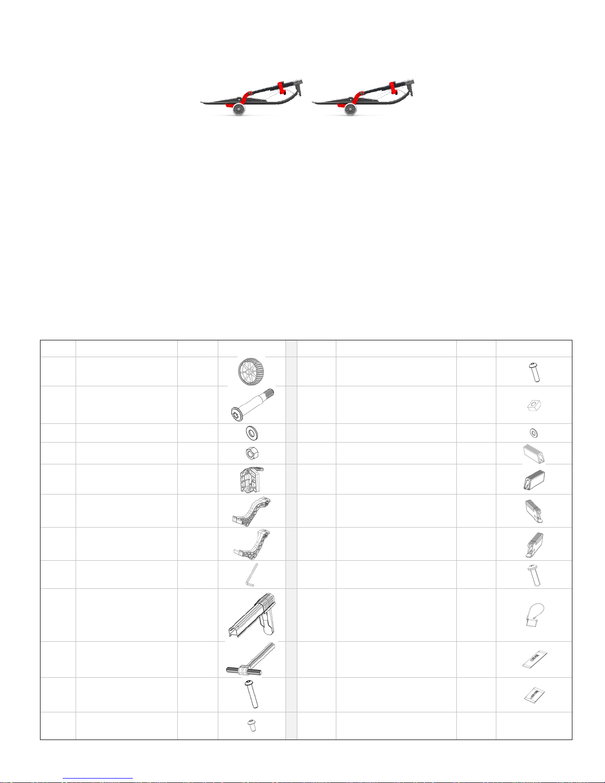
Parts list:
1 Wheel 4
2 Axle bolt 4
3 Washer, ½” 4
4 Nut, ½-13 4
5
6 Arm, Left 2
7 Arm, Right 2
8 Hex Wrench, 5/32 1
9
Telescoping
Handle
2
2
13
8
14 Nut, Square, 1/4-20 12
15 Washer, ¼” 10
16 Cover, Finger, Right 2
17 Cover, Finger, Left 2
18
Extender, Finger,
Right
1
19 Extender, Finger, Left 1
20
21
Safety Pin w/ lanyard
and Caution Card
4
2
10 T-Handle 2
11
12
- Page 1 - CI05067, rev B
BHCS, Hex, 1/4-
20 x 1.5”
2
2
22 Grease, 1cc 1
23 Vibratite, 1cc 1
Page 2
Assembly:
1. Cut the Vibrati te packet (23) and empty into a disposable container. Paint the last five threads of all the bolts in
the kit (11, 12, and 13), including the axles (2). Wait ten minutes for the Vibratite to dry before proceeding with
screws.
2. Remove the arms from the T-handles, which have been installed in the storage position for shipping. Use a flat
blade screwdriver to spread the arm clamp apart if necessary to ease removal.
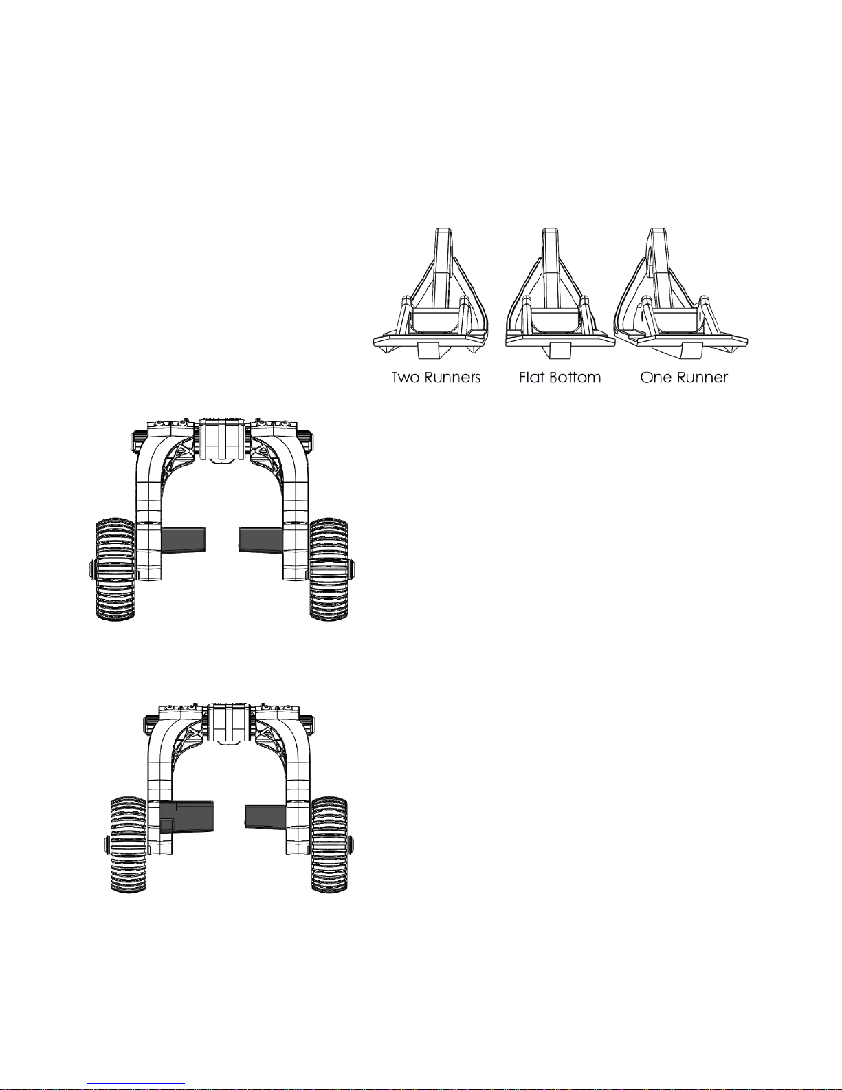
3. Determine which type of ski you are
using to determine the finger covers
you will use. Most snowmobile skis are
flat on the bottom, or have one or two
raised runners on the ski undersides to
help grip. The image to the right shows
the skis from the rear.
3a. For skis that are flat or have even runners, assemble the short
finger covers (16 and 17 - be sure to use the left cover on the left
arm, and right on right). Tap the rubber on a hard surface to ensure it
is fully seated. Secure with a self-tapping screw (20).
3b. For skis with uneven keels or carbides (i.e. SkiDoo Pilot skis and
others), use a finger extender (18 and 19) on the short side of the ski,
and a finger cover (16 or 17) on the long keel/carbide si de. Tap the
rubber on a hard surface to ensure it is fully seated. Secure with selftapping screws (20). The finger extenders’ height can be cut to
match your skis. Use the horizontal lines on the extenders as a guide.
This will make your Sled Wheels left or right handed, so be sure to
use them on the correct ski, or your skis will not sit flat.
- Page 2 - CI05067, rev B
Page 3
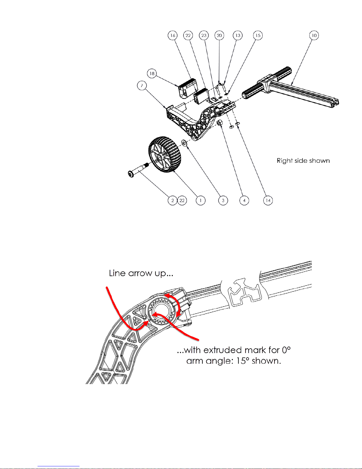
4. Apply one fourth of the
grease (22) to each axle (2)
and assemble a wheel (1),
½” washer (3), arm (6 and
7), and hex nut (4).
Tighten the axle until snug,
then tighten the axle 1/4 1/2 turn more with a T-55
Torx wrench. Repeat for
each of the three remaining
wheels.
5. Slide the assembled arms
onto the splined T-Handle
(10) and adjust the arms
approximately ½” wider
than the ski. It may be
useful to spread the arm
clamp with a flat blade
screwdriver. Some sleds
have spindle bolts that stick
beyond the edge of the ski,
for these sleds adjust the
arms wider to avoid the
bolt (or cut the excess bolt off). The arm angle can be adjusted 15° to accommodate tall or short ski loops. Most
sleds work best at 15°. Use two ¼-20 x 1.0” (13), two ¼” washers (15), and two ¼ square nuts (14) to secure the
arms in place using the supplied 5/32” hex wrench (8). Do not overtighten. Make sure both arms are installed at
the same angle.
- Page 3 - CI05067, rev B
Page 4

6. Slide the Saddle/Latch assemblies (5) over the Telescoping Handles (9) with the latch side first. Slip a ¼” square
nut (14) into the Telescoping Handle T-slot, and secure with a ¼-20 x 1.5” screw (11), and a safety pin/lanyard
assembly (21), using the lanyard loop as a washer. The saddle/latch should be about 1” from the ski stop, and will
be adjusted later. Leave the safety pin out of its hole in the latch.
7. Place a ¼” square nut in the T-slot of the T-Handle and then slide a Telescoping handle onto the T-handle, lining
up the nut with the hole in the Telescoping Handle. Secure the handle about 6” extended with a ¼-20 x 0.5”
screw (12) and ¼” washer (15). The extension will be adjusted to the ski later.
- Page 4 - CI05067, rev B
Page 5

Adjustment:
Key adjustments
1. If not done previously, adjust the width of each Sled Wheel assembly to be approximately ½” wider than the ski.
Include space to avoid the spindle screw if it sticks out past the sk i. Tighten, but do not over tighten the arm
clamp screws.
- Page 5 - CI05067, rev B
Page 6

2. Position one Sled Wheel assembly
above the ski so that the Sled Wheels
axle is directly above the ski spindle
axle. Loosen the Telescoping handle
screw and move the handle so it hits the
end of the ski. Tighten the screw.
3. Adjust the saddle/latch assembly so that
the latch will close at the peak of the ski
loop. Tighten the saddle screw.
4. Loosen the latch adjustment screw three
turns so that the lower portion of the
latch is moveable.
- Page 6 - CI05067, rev B
Page 7

5. Grab one Sled Wheel assembly by the handle, hold it vertically, and slide the fingers under the ski until the wheel
axle is in line with the spindle axle. You may need to lift the ski loop to create space under the ski. R otate th e
assembly down to raise the ski and check the length of the telescoping handle. Adjust as necessary to keep the
Sled Wheels axle and the spindle axle in line .
6. When the handle and saddle are in place,
and the Sled Wheels assembly is
installed onto the ski, the latch should
swing open and close around the ski
loop. Slide the latch up until it just
touches the ski loop and tighten the
screw. Do not over-tighten.
7. Fine adjustment: If the ski tips forward or backward, Sled Wheels need slight adjustments. If the ski tips
forward, the Sled Wheels axle is behind the ski spindle axle. Shorten the telescoping handle until the two axles
line up. Conversely, if the ski tips backwards, lengthen the telescoping handle. Also, check your ski bushings;
they should be tight and not worn. Good bushings will help your ride and help keep your ski horizontal when
riding with Sled Wheels.
8. Adjust the second assembly to the same locations as th e first.
- Page 7 - CI05067, rev B
Page 8

Attach to skis:
1. Grab one Sled Wheel assembly by the handle, hold it vertically, and slide the fingers under the ski until the wheel
axles are in line with the spindle axle. You may need to lift the ski loop to create space under the ski. Rotate the
assembly down to raise the ski until the latch closes around the ski loop. Install and lock the safety pin. Repeat
for the second ski.
Caution: Do not exceed 12 miles per hour while driving on Sled Wheels.
Detach from skis:
1. Remove safety pin from latch. Push down on handle to remove the weight of the snowmobile, and push the latch
lever to release the ski loop.
2. Slowly move the handle up. Remove Sled Wheels from the ski, lifting the ski loop if necessary. Close latch and
replace safety pin. Store fully assembled, ready for your next ride!
Caliber, Inc. warrants that this product will be free from defects in material or workmanship under normal use, installation and service. Caliber, Inc. reserves the right, before
having any obligation under this limited warranty, to inspect the damaged Caliber product. All warranty shipping costs for inspection shall be borne solely by the purchaser. This
limited warranty is non-transferable. Contact Caliber, Inc. at www.caliberproductsinc.com
Caliber, Inc. shall not be liable for any special, incidental or consequential damages, including, but not limited to, lost revenues, lost profits, personal injury, damage to property,
and third-party claims, arising out of any warranty, contract, statutory or tort. Notwithstanding the term of any limited warranty or any warranty implied by law, or in the event
that any limited warranty fails of its essential purpose, in no event will Caliber’s entire liability exceed the purchase price of this product
CALIBER®
952-985-9999
www.caliberproductsinc.com
- Page 8 - CI05067, rev B
CALIBER, INC. LIMITED LIFETIME WARRANTY
or at 952-985-9999 for warranty service procedures.
DISCLAIMER
 Loading...