

Page 1
PyroMini Series
Operator’s Guide
Page 2

2
INTERNATIONAL OPERATOR’S GUIDE
DE: Laden Sie die Bedienungsanleitung unter:
EN: Download the operator’s guide at:
ES: Descargue el manual de instrucciones en:
FR: Téléchargez le manuel d’instructions sur:
IT: Scarica il manuale di istruzioni su:
www.calex.co.uk/pyromini
Page 3

3
The PyroMini Series is a range of miniature non-contact infrared temperature sensors with
separate electronics modules.
All models have an adjustable emissivity setting and are capable of measuring a wide variety
of target materials, including food, paper, textiles, plastics, leather, tobacco, pharmaceuticals,
chemicals, rubber, coal and asphalt.
General-purpose PyroMini models measure non-reflective non-metals, or painted or coated
metals, at temperatures from -20°C to 1000°C.
PyroMini 2.2 models have a shor t measurement wavelength. They are ideal for measuring
reflective surfaces such as uncoated iron and steel, as well as many other high-temperature
applications. They are capable of measuring temperatures from 100°C to 2000°C.
The optional touch screen interface provides temperature indication, alarms, sensor
configuration and data logging to MicroSD Card. The optional high-temperature sensing head
on general-purpose models may be used in ambient temperatures of up to 180°C without
cooling. The low-noise cable on high ambient temperature models is resistant to interference
from movement, so it is ideal for mounting on moving objects such as robot arms.
A choice of optics is available to measure small or large targets at short or long distances, and
there is a choice of 4-20 mA, RS485 Modbus and alarm relay outputs.
SPECIFICATION
PyroMini PyroMini 2.2
Temperature Range See table of Model Numbers
Maximum Temperature
Span (-CRT models)
Full temperature range (up to 1550°C)
Minimum Temperature
Span (-CRT models)
100°C
Output 4 to 20 mA or RS485 Modbus
Field of View See table of Model Numbers
Accuracy ± 1°C or 1%,
whichever is greater
± 2°C or 1%,
whichever is greater
Repeatability ± 0.5°C or 0.5%, whichever is greater
Emissivity Setting Range 0.20 to 1.00 0.10 to 1.00
Emissivity Setting Method • -CB models: via two rotary switches
in electronics module
• -BB and -BT models: via RS485
• -CRT and -BT models: via touch screen
Response Time, t
90
240 ms (90% response)
Spectral Range 8 to 14 μm 2.0 to 2.6 μm
Supply Voltage 24 V DC ± 5%
Maximum Current Draw 100 mA
Maximum Loop Impedance -CB and -CRT models: 900 Ω (4 to 20 mA output)
Alarm Relays (-CRT
models)
2 x Single Pole Changeover alarm relays rated
24 V DC, 1 A, isolated 500 V DC
Page 4

4
MECHANICAL
Sensing head Electronics Module
Construction Stainless Steel
316
Die-cast Aluminium
Major Dimensions
Ø18 x 45 mm
98(w) x 64(h) x 36(d) mm
Mounting M16 x 1 mm
thread
Two M4 screws for wall mounting (see
diagram)
Cable Length (sensing head
to electronics module)
1 m (standard), up to 30 m (optional)
Weight with 1 m Cable 390 g (approx)
Cable Connections Removable screw terminal blocks (see Connections).
Conductor size: 28 AWG to 18 AWG
Output Cable Gland Suitable for cable diameters 3.0 to 6.5 mm
ENVIRONMENTAL
Sensing Head Electronics
Module
(without touch
screen)
Electronics
Module (with
touch screen)
Environmental Rating IP65 (NEMA 4) IP65 (NEMA 4) –
Ambient Temperature
Range
See table of
Model Numbers
0°C to 60°C 0°C to 60°C
Relative Humidity Ma ximum 95%
non-condensing
Ma ximum 95%
non-condensing
Maximum 95%
non-condensing
CE Marked Yes Ye s Ye s
RoHS Compliant Yes Ye s Ye s
The PyroMini series conforms to EMC Directive EN61326-1:2006 (Electrical equipment for
measurement, control and laboratory use – Industrial) as well as industrial standards for
electromagnetic immunity and emissions.
Page 5

5
MODEL NUMBERS
The following combinations of ambient temperature range, optics, measured temperature
range, output and interface are available:
Series
Sensing Head
Operating
Temperature
Range
Field of View
Temperature
Range
Output
and
Interface
PM
General Purpose
(8-14 μ m )
MA (0-60°C)
21 (2:1)
151 (15:1)
301 (30:1)
CF (close focus)
LT (-20 - 100°C)
MT (0 - 250°C)
HT (0 - 500°C)
XT (0 - 1000°C)
CB
CT (-20 - 1000°C)
CRT
BB
BRT
HA (0 -18 0 °C)
JA (0-12 0 °C)
201 (2 0:1)
LT (-20 - 100°C)
MT (0 - 250°C)
HT (0 - 500°C)
XT (0 - 1000°C)
CB
CT (-20 - 1000°C)
CRT
BB
BRT
PM 2.2
High Temperature
(2.2 μm)
(all models
0-70°C)
151 (15:1) PT (100 - 400°C)
CB
CRT
BB
BRT
251 (25:1)
751 (75:1)
CF (close focus)
MT (250 - 1000°C)
HT (450 - 2000°C)
SENSING HEAD OPERATING TEMPERATURE RANGE
-JA and -HA models withstand high ambient temperatures without cooling. They are available
with -201 (20:1) optics only.
There is no need to supply cooling air or water, and the miniature sensing head is much smaller
than bulky, cooled sensors.
Page 6
6
(PyroMini 2.2 - High Temperature)
Distance: Sensor to object (inches)
Distance: Sensor to object (mm)
12
60
135
0.6
2.4
5.3
0 59.1 118.1
0 1500 3000
Spot Dia.
(inches)
Spot Dia.
(mm)
Spot Dia.
(inches)
Spot Dia.
(mm)
Distance: Sensor to object (inches)
Distance: Sensor to object (mm)
12
100
215
0.6
3.9
8.5
0 59.1
118.1
59.1
118.1
0 1500 3000
015003000
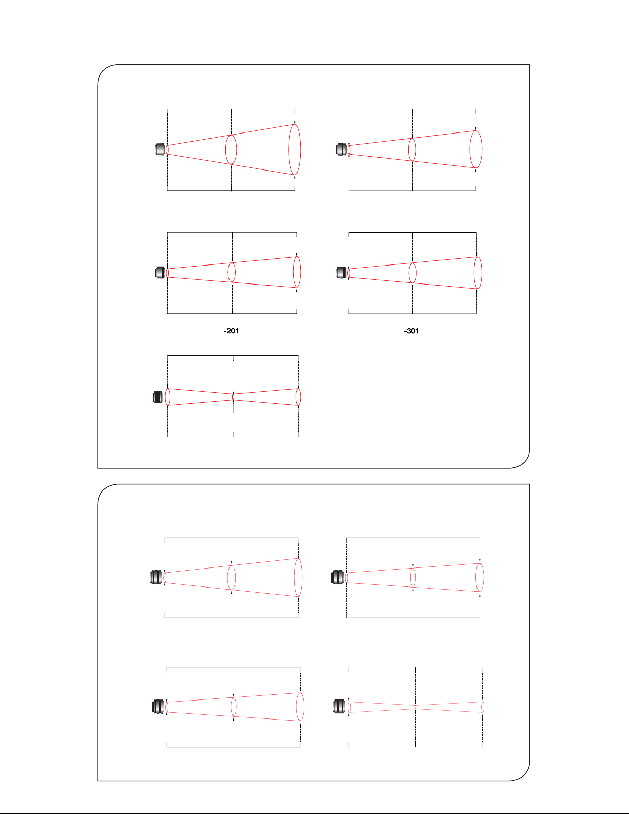
D:S 25:1D:S 15:1
-251
Distance: Sensor to object (inches)
Distance: Sensor to object (mm)
12
20
55
0.6
0.8
2.2
0
Spot Dia.
(inches)
Spot Dia.
(mm)
D:S 75:1
-751
-151
Spot Dia.
(inches)
Spot Dia.
(mm)
Distance: Sensor to object (inches)
Distance: Sensor to object (mm)
12
7.5
30
0.6
0.3
1.2
019.
73
9.4
0500 1000
-CF
(PyroMini - General Purpose)
FIELD OF VIEW
11.9
0
Spot Dia.
(inches)
Spot Dia.
(mm)
Distance: Sensor to object (inches)
Distance: Sensor to object (mm)
61.9
111.9
0.5
2.4
4.4
048
100200
D:S 2:1
-21
Distance: Sensor to object (inches)
Distance: Sensor to object (mm)
11.9
45.2
78.6
0.5
1.8
3.1
019.
73
9.4
0500 1000
Spot Dia.
(inches)
Spot Dia.
(mm)
D:S 15:1
-151
Distance: Sensor to object (inches)
Distance: Sensor to object (mm)
11.9
36.9
61.9
0.5
1.5
2.5
019.739.4
0500 1000
Spot Dia.
(inches)
Spot Dia.
(mm)
D:S 20:1
Distance: Sensor to object (inches)
Distance: Sensor to object (mm)
11.9
28.6
45.2
0.5
1.1
1.8
019.
73
9.4
0500 1000
Spot Dia.
(inches)
Spot Dia.
(mm)
D:S 30:1
Spot Dia.
(inches)
Spot Dia.
(mm)
Distance: Sensor to object (inches)
Distance: Sensor to object (mm)
11.9
0.5
0
0
5.0
0.20
100
3.9
12.5
0.49
200
7.9
-CF
Diameter of target spot measured
versus distance from sensing
head at 90% energy. Sensors may
be used at longer distances than
these diagrams show. There is no
maximum measurement distance
in clean air.
Page 7
7
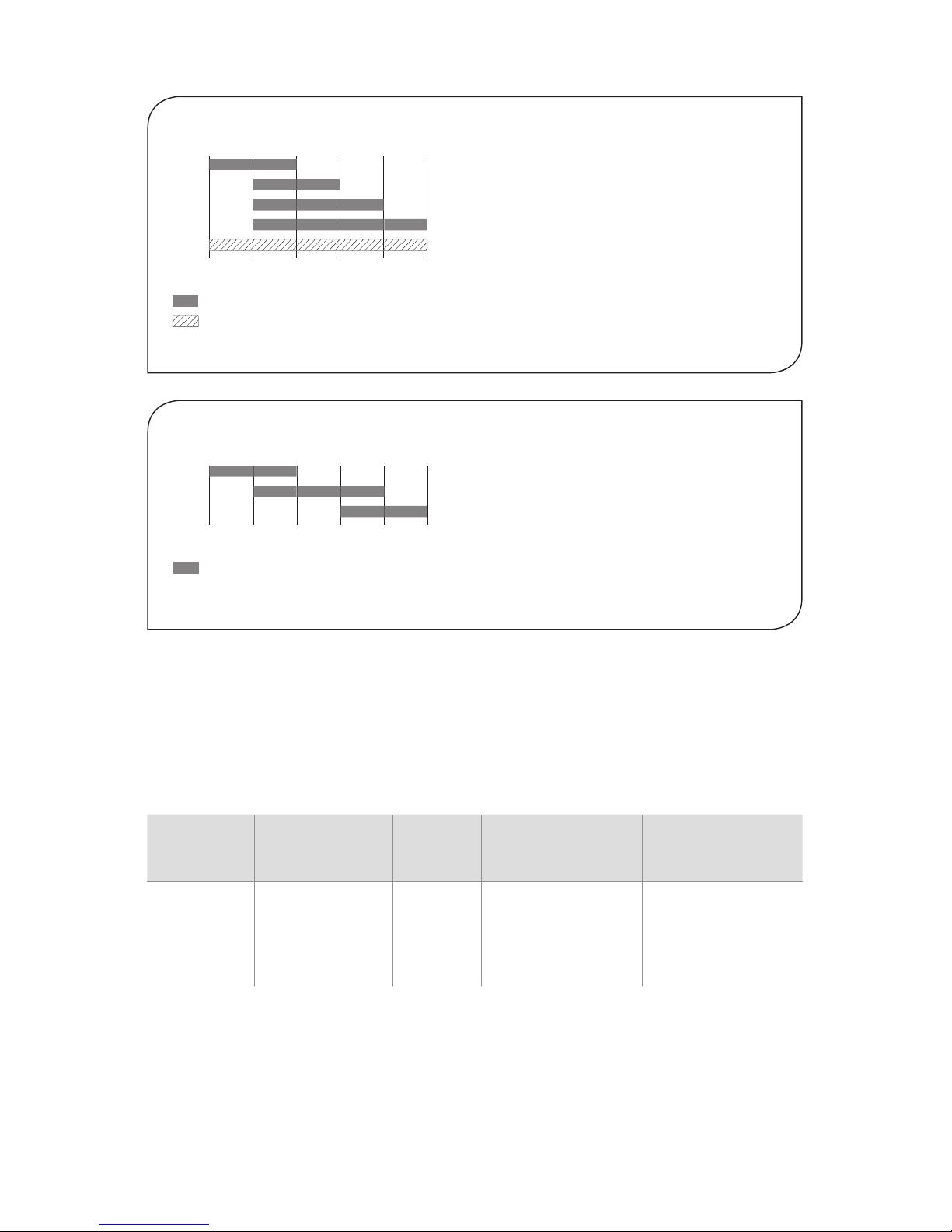
MEASUREMENT TEMPERATURE RANGE (°C)
-20
-LT
-MT
-HT
-XT
-CT
0 100
Fixed (e.g. -MT: 0°C @ 4 mA, 250°C @ 20 mA)
-CRT models: 4 to 20 mA output configurable within this range
-BRT and -BB models: Digital output, full temperature range
250 500 1000
OUTPUT AND INTERFACE
-CB 4 to 20 mA output, no touch screen
-CRT 4 to 20 mA output and two alarm relay outputs, with touch screen
-BB RS485 Modbus output, no touch screen
-BRT RS485 Modbus output and two alarm relay outputs, with touch screen
EXAMPLE: PM-MA-301-CT-BRT
Series
Sensing Head
Operating
Temperature
Optics
Temperature
Range
Output and
Interface
PM
PyroMini
-MA 0°C to 60°C -301 3 0:1
divergent
-CT configurable
within the limits: -20
to 1000 °C
-BRT RS485
Modbus output
and two alarm relay
outputs, with touch
screen
(PyroMini - General Purpose)
(PyroMini 2.2 - High Temperature)
100
-PT
-MT
-HT
250 400
-CB models: Fixed 4 to 20mA output scale (e.g. -MT: 250
o
C @ 4mA,1000oC @ 20 mA)
-CRT models: 4 to 20 mA output configurable within this range
-BRT and -BB models: Digital output, full temperature range
450 1000 2000
Page 8

8
EMISSIVITY ADJUSTMENT (-CB MODELS)
The emissivity setting on -CB models may be adjusted via two rotary switches inside the electronics
box. To adjust the emissivity setting:
Set the left switch to the first digit after the decimal point (0.1).
Set the right switch to the second digit after the decimal point (0.01).
To enter an emissivity setting of 1.00, set both switches to 0.
If the selected emissivity setting is lower than the minimum, the sensor will default to an emissivity
setting of 0.95.
For example:
Left switch Right switch Emissivity setting
6 3 0.63
0 0 1.00
TOUCH SCREEN (-CRT AND -BRT MODELS)
The optional backlit touch screen interface mounted in the lid of the electronics module provides
a large, bright display of the measured temperature, as well as options for full configuration of
the sensor. The graph view shows the history of the measured temperature.
In alarm conditions, the display changes colour to provide an immediate and obvious alarm
indication. Alarm modes and levels can be configured via the touch screen.
TOUCH SCREEN SPECIFICATIONS
Touch Screen
Display Format
2.83” (72 mm) resistive touch TFT, 320 x 240 pixels, backlit
Configurable
Parameters
Temperature range, temperature units, emissivity setting, reflected energy compensation, alarms, signal processing, Modbus
address (-BRT models), date and time, data logging
Temperature Units °C or °F configurable
Temperature
Resolution
0.1°
Alarm Configuration Two alarms with adjustable level, individually configurable as HI
or LO. Alarm 2 can be set to target temperature or sensing head
internal temperature
Signal Processing Average, peak hold, valley hold, minimum, maximum
EXAMPLE: PM2.2-251-MT-BRT
Series
Sensing Head
Operating
Temperature
Measurement
Temperature
Range Optics
Output and
Interface
PM2.2
PyroMini 2.2
251
25:1 divergent opticsMT250°C to 1000°C
-BRT RS485
Modbus output
and two alarm relay
outputs, with touch
screen
Page 9

9
User Interface
Default View
Temperature View
Displays a large indication of the measured temperature. The background
turns bright red when an alarm is activated.
Setting Temperature
Press “°C” to switch to °F and vice versa. The units are changed throughout the interface.
Selecting Displayed Temperature
Press the temperature display to select which reading is shown:
Filtered Temp
The measured temperature, with averaging and hold processing. This temperature is output
by the sensor on the 4 to 20 mA output (-CB and -CRT models).
Average Temp
The measured temperature with averaging but without hold processing.
Unfiltered Temp
The unprocessed measured temperature.
MicroSD Card status.
This icon is displayed when a MicroSD card is inserted, and flashes when
data logging is in progress.
This icon is displayed when scheduled data logging is enabled and has yet
to begin.
List View
Displays a list of the measured temperatures, alarm state and data logging
state.
Filtered Temp: The measured temperature, with averaging and hold processing.
Unfiltered Temp: The unprocessed measured temperature.
Average Temp: The Unfiltered Temperature averaged over the period specified in “Output
Pro c es s in g ”.
Maximum Temp: The highest temperature measured during the hold period, with averaging.
Minimum Temp: The lowest temperature measured during the hold period, with averaging.
Sensor Temp: The internal temperature of the sensing head.
Reflected Temp: The reflected energy compensation temperature, as specified in “Emis-
sivity and Compensation”.
Page 10

10
Lock/Unlock
Prevents settings being changed via a four-digit numerical code.
The default password is 1234.
Change Password
Enter, confirm and save a new four-digit code.
Start/Stop Logging
GO
Manually begins or ends data logging (requires MicroSD Card, available
separately).
If Scheduled Start is enabled in Settings > Data Logging, then logging cannot
be started manually.
To manually start logging, you must first disable Scheduled Start.
Graph
Displays the recent history of the Filtered Temperature and the Sensor
Temperature. To scroll backwards and forwards in time, touch the graph and
drag it. The graph stores the most recent 24 hours of temperature data.
Reset Graph
Clears and restarts the graph.
Real-Time Scrolling View
Returns the graph to the real-time scrolling view, showing the most recent
measurements.
STOP
Acknowledge Alarms
Switches the relay outputs for triggered alarms to their normal, untriggered
state. The background of the Temperature View, List View and Graph View will
stay red, and the alarms will not be triggered again, until the alarms are reset
(see “Alarms” below). Alarms can be acknowledged when the display is locked.
Settings
Access the configuration parameters. Press Apply
to save the settings, or Exit to leave the screen
without saving.
If Settings icon is grey, the interface is locked.
See “Lock/Unlock”.
Page 11

11
Settings
Date & Time
Change the date and time for data logging purposes.
The clock is reset when the power is switched off, unless a battery is fitted.
Output Processing
f
(x)
AVERAGING PERIOD
Set the time, in seconds, over which the measured temperature is averaged.
Note: averaging prevents the sensor from following rapid temperature
changes. Minimum: 0 (no averaging). Maximum: 60.
HOLD MODE
Peak
The sensor holds the maximum temperature steady for the Hold Period. After
this, the sensor responds normally. If the sensor detects a higher temperature,
it holds this temperature steady for the Hold Period.
Valley
Similar to Peak Hold mode except that the sensor outputs the minimum
detected temperature steady for the Hold Period.
Off
Disables hold processing.
HOLD PERIOD
Set the time, in seconds, for the sensor to hold the temperature as above.
Minimum: 0 (no hold processing). Maximum: 1200.
Data Logging
Sample Period
The time, in seconds, between samples. Minimum: 1. Maximum: 86,400
(1 day).
Number of Samples
The number of samples to collect before logging stops. Minimum: 0
(continuous logging). Maximum: 86,400 (1 day of data if Sample Period = 1
second).
Enable Scheduled Start
The sensor begins logging at the Date and Time specified. Logging can also
be started and stopped manually.
Date and Time
The date and time for scheduled logging to start.
Emissivity and Compensation
Emissivity and Compensation
Enter the emissivity of the target. Target emissivity can be determined
experimentally, or estimated using an emissivity table. For more information,
contact Calex.
Enable Reflected Energy Compensation
If enabled, compensates for errors caused by reflected energy from hotter or
colder objects.
Reflected Temperature
Enter the temperature of the surroundings of the target for Reflected
Energy Compensation.
Page 12

12
4 to 20 mA Output (-CRT models)
mA
Set the temperature range limits for the 4 to 20 mA output.
Temperature at 4 mA
The lower temperature range limit.
Temperature at 20 mA
The upper temperature range limit.
Please note
The difference between the temperatures at 4 mA and at 20 mA must be at
least 100°C. The temperature at 20 mA must be greater than the temperature
at 4 mA.
Modbus Address (-BRT models)
The current Modbus address of the sensor is displayed. Enter a new address,
then press Apply to save it to the sensor. Cycle the power to use the new
address.
Minimum: 1. Maximum: 247.
Alarms
Configure the settings for Alarm 1 and Alarm 2 separately, and configure alarm
logging settings.
Manually Reset Alarms
If an alarm has been triggered, allows both alarms to be triggered again.
Alarms will not be triggered again until they are reset, either automatically or
manually.
Alarm settings
Alarm 1 and Alarm 2
Alarm Set Point
The temperature at which the alarm is triggered.
Hysteresis
The temperature difference between the Alarm Set Point and the reset
temperature. Hysteresis is only used when Automatic Reset is enabled. Please
see the Alarm Operation diagrams below for more information.
Minimum: 0°C (hysteresis disabled).
Filtered Temperature or Sensor Temperature (Alarm 2 only)
Select the temperature monitored by Alarm 2.
Alarm Type
High
The alarm is triggered when the temperature rises above the Alarm Set Point.
Low
The alarm is triggered when the temperature drops below the Alarm Set Point.
Off
The alarm is disabled.
Page 13

13
ALARM OPERATION WITH HYSTERESIS & AUTOMATIC RESET
Alarm triggered Alarm reset
A
larm Set Point
Hysteresis
Temperature
Time
Alarm triggered Alarm reset
Alarm Set Point
Hysteresis
Temperature
Ti
me
High Alarm with Automatic Reset
Low Alarm with Automatic Reset
The PyroMini can be used as a standalone data logger.
PyroMini models -CRT and -BRT include a MicroSD card slot for data logging, which can be
configured via the touch screen interface. The user can select the sample rate and the number
of samples to be taken and schedule the data logging to start at a certain time.
With a 2 GB card, the user can store 28.4 million readings, which provides almost 1 year’s
worth of data at the fastest possible sample rate of 1 per second.
Data is stored on the MicroSD card in .csv format and can be viewed and edited easily using
spreadsheet software.
A MicroSD card with SD card adapter is available as an optional accessor y.
The MicroSD card slot and battery holder are located on the touch screen circuit board in the
lid of the electronics module. Readings are time and date stamped using the sensor’s internal
clock. The clock is reset when the power is disconnected, or it will continue if the optional
battery is fitted.
Reset
Automatic
The alarm is acknowledged and reset automatically when the temperature
reaches the reset temperature (see Hysteresis). It can also be acknowledged or
reset manually.
Manual
The alarm is acknowledged by pressing Acknowledge on the Temperature
View or List View, and reset by pressing Reset on the Alarms screen.
Alarm Logging
Alarm events can be logged to the MicroSD Card. Alarm log files and settings
are independent from Data Logging.
Log Trigger Time
The time that an alarm is triggered will be logged.
Log Data While Triggered
Data logging will start when an alarm is triggered. 1 sample is logged per
second. Logging stops when both alarms are reset.
Log Acknowledge Time
The time that the alarm is acknowledged will be logged.
Log Reset Time
The time that the alarm is reset will be logged.
Acknowledge
Reset
Page 14

14
DATA LOGGING SPECIFICATIONS
Data Logging Interval 1 to 86,400 seconds (1 day)
MicroSD Card Max. capacity: 32 GB (not included)
Internal Clock Battery 1 x BR 1225 3V (not included)
Variables Logged Target temperature, sensing head temperature, electronics
module temperature, max, min, average, emissivity setting,
reflected energy compensation temperature
File format .csv
Configurable
Parameters
Sample period, number of samples, scheduled start date and
time
Modbus address range 1 to 247
USING THE PYROMINI AS A DATA LOGGER
1. Insert a MicroSD card into the holder on the circuit board inside the lid of
the electronics module.
2. To retain the date and time when the sensor is switched off, fit a battery to
the holder on the circuit board inside the lid.
3. Replace the lid and connect the sensor power supply.
4. To set the number of samples to be logged, the time period between
samples, and, if required, to schedule data logging to automatically start,
press Settings to access the Settings menu, then press Data Logging to
access the Data Logging options.
5. To save data logging settings, press Apply
GO
6. To manually star t data logging, press Go on the Temperature View or List
Vi ew.
7. While logging is in progress, the Logging Icon flashes on the Temperature
View and List View.
STOP
8. To stop data logging, press Stop.
9. To transfer data to a computer, remove the MicroSD Card from the sensor,
insert the card into the SD Card adapter (supplied with MicroSD Card,
accessory model MSD) and insert the adapter into an SD Card reader.
Page 15

15
Data is saved to the MicroSD Card in .csv format. This file format can be opened or imported by
spreadsheet software such as Microsoft Excel.
A new folder is created on the MicroSD Card for each day that data is logged.
A new log file is created every time logging is started. The start time is used as the file name.
DIMENSIONS & ACCESSORIES
Thread M16 x 1 mm
Standard length
18
48
18
64
86
98
20
36
10004513
12
Ø 18.6
Air Purge Collar
Sensing Head
4
18
Ø 40
Ø 29
25
50
1/8" BSP
air fitting
Removable spigot fitted to
type APSN for use with
all optics except 2:1. Not fitted
to type APSW for -21 models.
Mounting Nut
(included)
Ø 18
Electronics Module
Touch screen
(optional)
72 mm (2.83")
Cable glands:
14 mm AF
Mounting
holes: use M4
CSK screws
(supplied)
36
Touch screen
(optional)
72 mm (2.83”)
MicroSD Card
Battery
(use 1 x BR 1225 3V)
INSTALLATION OF MICROSD CARD AND BATTERY
Page 16

16
10.0
40.0
50.0
50.0
40.0
9.0
15.0
25.0
25.0
Ø16.0
60° Rotation 60° Rotation
60° Rotation
9.0
48.0
Fixed Bracket (FBS) Adjustable Bracket (ABS)
2 x Mounting Holes M4 Clearance 2 x Mounting Holes M4 Clearance
Material: Stainless steel
Bracket thickness: 2 mm
9.0
24.024.0
A range of accessories to suit different applications and industrial environments is available.
These may be ordered at any time and added on-site. The following accessories are available
from Calex:
Fixed mounting bracket (see above for dimensions): Allows rotational adjustment in one
dimension. Model number: FBS.
Adjustable mounting bracket (see above for dimensions): Allows rotational adjustment in two
dimensions. Model number: ABS.
Air purge collar (see above for dimensions): The air purge collar is used to keep dust, fumes,
moisture, and other contaminants away from the lens. It must be screwed fully onto the sensing
head. Air flows into the 1/8” BSP fitting and out of the front aperture. Air flow should be 5 to 15
l/min. Clean or ‘instrument’ air is recommended. Model APSW is for use with sensors with 2:1
optics. Model APSN is for use with all other models.
Laser sighting tool: When fitted to the sensor during installation or re-alignment, the laser
sighting tool pinpoints the centre of the measured spot. Model number: LSTS.
MicroSD Card: Stores logged data. For use with -BRT and -CRT models. Includes SD Card
adapter. Model number: MSD.
Protective plastic or silicon windows: Helps protect the lens from mechanical or chemical
damage. Quick and easy to replace. For use with general-purpose models only. Model number:
PWS / SIWS.
Dual laser sighting bracket: Allows continuous laser sighting at the same time as using the
sensor. Model number: DLSBFS (fixed), DLSBAS (adjustable)
6-sensor touch screen hub (-BB and -BRT models): Multi-channel temperature display,
configuration and logging for up to 6 Modbus sensors. Model number: PM180.
OPTIONS
The following options are available. Options are factory installed and must be ordered with the
sensor.
Calibration Certificate: UKAS traceable certificate showing the measured temperature at
three points across the sensor’s temperature range. Model number: CALCERTA.
Extended Cable (30 m maximum total cable length): 1 m cable is supplied with each sensor
as standard. Extra cable can be added to this in increments of 1 m. Model number: PMCE (-MA
models), PMCEHT (-HA models), PM2.2CE (PM2.2 models).
Page 17

17
INSTALLATION
The installation process consists of the following stages:
Preparation
Mechanical installation
Electrical installation
Please read the following sections thoroughly before proceeding with the installation.
PREPARATION
Ensure that the sensor is positioned so that it is focused on the target only.
DISTANCE AND SPOT SIZE
Sensor
CORRECT
INCORREC
T
Background
T
arget larger
than spot size
T
arget smaller
than spot size
The size of the area (spot size) to be measured determines the distance between the sensor and
the target. The spot size must not be larger than the target. The sensor should be mounted so
that the measured spot size is smaller than the target.
AMBIENT TEMPERATURE
The sensing head withstands up to 60°C, 70°C, 120°C, or 180°C, without cooling, depending
on the choice of model. See “Model Numbers” for more information.
Avoid thermal shock. Allow 20 minutes for the unit to adjust to large changes in ambient
temperature.
ATMOSPHERIC QUALITY
Smoke, fumes, dust or steam can contaminate the lens and cause errors in temperature
measurement. In these types of environment the air purge collar should be used to help keep
the lens clean.
Page 18

18
INTERFERENCE FROM MOVEMENT
The low-noise sensing head cable on -HA models is resistant to interference caused by
movement. The sensing head may be mounted on moving machinery such as robot arms
without affecting the accuracy of the measured temperature.
ELECTRICAL INTERFERENCE
The PyroMini is tested to industrial standards for electromagnetic compatibility (EMC) as shown
in Specifications at the beginning of this manual.
To minimise electromagnetic interference or ‘noise’, the sensor should be mounted away from
motors, generators and such like.
POWER SUPPLY
Be sure to use a 24 V DC (100 mA) power supply.
MECHANICAL INSTALLATION
All sensors come with a 1 m cable and a mounting nut as standard. Longer cables are available
to order. The sensor can be mounted on brackets or cut-outs of your own design, or you can
use the fixed or adjustable mounting bracket accessories.
Note: The sensor housing must be connected to earth at one point, either the housing
of the sensing head, the electronics module, or the output cable shield termination. To
avoid ground loops, please ensure the sensor is grounded at only one of these points.
Page 19

19
ELECTRICAL INSTALLATION
CONNECTIONS
Sensing Head Cable Colour Codes
Depending on the sensing head type, there will be 4 or 5
wires, with the following combinations of colour codes:
Terminal label Colours
TP+ Yellow Blue with white line
TP- Green White with blue line
TH+ Brown/Red Blue
GND White White
VCC Grey (PyroMini 2.2 only)
OP+
OP-
PWR-
PWR+
NO1
COM1
NC1
NO2
COM2
NC2
A
24 V DC
100 mA
4 to 20
mA
x 0.10
x 0.01
Emissivity
adjustment
switches
(-CB models)
Relay outputs
(-CRT models)
Sensing head
-CB and -CRT models
+
-
Removable
screw terminals
OP+
OP-
PWR-
PWR+
NO1
COM1
NC1
NO2
COM2
NC2
A
24 V DC
100 mA
4 to 20
mA
x 0.10
x 0.01
Emissivity
adjustment
switches
(-CB models)
Relay outputs
(-CRT models)
Sensing head
OP-
NO1
COM1
NC1
NO2
COM2
NC2
24 V DC
100 mA
Relay outputs
(-BRT models)
Sensing head
Modbus
Master
GND
RS-
RS+
-CB and -CRT models
-BB and -BRT models
+
-
OP+
PWR-
PWR+
Removable
screw terminals
Removable
screw terminals
+
-
When reconnecting the sensing head to
the electronics module, ensure the
shield drain wire is terminated to the
inside of the cable gland.
Page 20

20
WIRING (ALL MODELS)
Check the distance between the sensing head and the electronics module, and between the
electronics module and the instrumentation. If necessary, the sensor can be ordered with a
longer cable between the sensing head and the electronics module.
Do not extend or shorten the sensing head cable. The head and electronics module are
calibrated as a pair, and modifying the sensing head cable can affect the measurement
accuracy. Contact Calex for assistance.
The output cable from the electronics module should have an outer diameter between 3.0 and
6.5 mm, with conductors of size 28 to 18 AWG.
The terminal blocks in the electronics module may be removed from the circuit board for easy wiring.
Do not connect or disconnect the touch screen circuit board from the main circuit board while
the sensor is on.
WIRING (-BB AND -BRT MODELS)
When connecting several sensors in a single Modbus network, all of the sensors should be
connected via a junction box to a single network bus cable, running from the furthest sensor to
the Modbus Master.
Up to 247 sensors may be connected to a single Modbus network. Each sensor must have a
unique Modbus address. The Modbus address may be changed via the touch screen interface
on -BRT models, or via Modbus.
To help prevent data reflections, please ensure the cable between each sensor and the main
network bus is as short as possible. The network bus should be terminated with a resistor of
120 Ω between the RS+ and RS- wires. The PWR- wire of the bus should be connected to the
signal ground of the Modbus Master.
MODBUS OVER SERIAL LINE (RS485)
Interface
Baud rate 9600
Format 8 data, No parity, 1 stop bit
Reply delay (ms) 20
Supported functions
Read register 0x03, 0x04
Write single register 0x06
Write multiple register 0x10
Mask write register 0x16
Read/write 0 x 17
Page 21

21
The list below includes all available addresses:
R = Read W = Write (single, multiple or read/write) MW = Mask write
Address Length (words) Description R/W/MW
0x00 1 MODBUS slave address R/W*
0x02
2
Sensor identification register
Bits 0..19 - Serial number
Bits 20..23 - Sensor type
(12 = PyroMini, 14 = PyroMini 2.2)
Bits 24..26 - Sensor field-of-view
For PM-MA : 0 = 2:1, 1 = 15:1, 2 = 30:1
For PM-HA : 0 = 20:1
For PM2.2: 0 = x51-MT, 1 = x51-HT,
2 = 151-LT, 3 = 151-PT
Bits 28..32 - Reserved
R
0x06 1 Unfiltered object temperature R
0x08 1 Sensor temperature R
0x0A 1 Maximum temperature over hold period R
0x0C 1 Minimum temperature over hold period R
0x0E 1 Average temperature over hold period R
0x10 1 Filtered object temperature R
0x12 1 PCB temperature R
0x14
1
Emissivity (1 LSB = 0.0001)
Minimum 0.2000, Maximum 1.0000
R/W
0x16 1 Reflected temperature R/W
0x18
1
Sensor status register
Bits 0..1 - Reserved
Bit 2 - Hold processing on (1)/off (0)
Bit 3 - Hold peaks (1)/valleys (0)
Bits 4..6 - Reserved
Bit 7 - Reflected energy compensation
on (1)/off (0)
Bits 8..15 - Reserved
R/ W/MW
0x1A
1
Average period (1 LSB = 0.05 seconds)
Minimum 0.05 seconds, Maximum 60.00
seconds
R/W
0x1C
1
Hold period (1 LSB = 0.05 seconds)
Minimum 0.05 seconds, Maximum 1200.00
seconds
R/W
0x1E 1 Temperature at 4 mA
PM: Minimum -20°C, Maximum 900°C
PM2.2: Minimum 100°C, Maximum 1900°C
R/W
0x20 1 Temperature at 20 mA
PM: Minimum 80°C, Maximum 1000°C
PM2.2: Minimum 200°C, Maximum 2000°C
R/W
Page 22

22
Address Length (words) Description R/W/MW
0x22 1 Alarm 1 setpoint
Minimum -20°C, Maximum 1000°C
Minimum 100°C, Maximum 2000°C
R/W
0x 24 1 Alarm 1 hysteresis
PM: Minimum 0°C, Maximum 1000°C
PM2.2: Minimum 0°C, Maximum 1550°C
R/W
0x26 1 Alarm 1 status register
Bit 0 – Relay triggered (R)
Bit 1 – Visible alarm active (R)
Bit 2 – Alarm triggered (R)
Bit 3 – Auto reset (1)/manual reset (0)
(R/ W/MW)
Bit 4 – Alarm acknowledge (R/W/MW)
Bit 5 – Alarm reset (R/W/MW)
Bits 6..7 – Reserved
Bit 8 – High alarm (1)/low alarm (0) (R/W/MW)
Bit 9 – Alarm enabled (1)/disabled (0)
Bits 10..15 – Reser ved
R/ W/MW
0x28 1 Alarm 2 status register
Bit 0 – Relay triggered (R)
Bit 1 – Visible alarm active (R)
Bit 2 – Alarm triggered (R)
Bit 3 – Auto reset (1)/manual reset (0)
(R/ W/MW)
Bit 4 – Alarm acknowledge (R/W/MW)
Bit 5 – Alarm reset (R/W/MW)
Bit 6 – Reserved
Bit 7 – Filtered object temperature
(1)/head temperature (0) (R/ W/MW)
Bit 8 – High alarm (1)/low alarm (0) (R/W/MW)
Bit 9 – Alarm enabled (1)/disabled (0)
Bits 10..15 – Reser ved
R/ W/MW
0x2A 1 Alarm 2 setpoint
PM: Minimum -20°C, Maximum 1000°C
PM2.2: Minimum 100°C, Maximum 2000°C
R/W
0x2C 1 Alarm 2 hysteresis
PM: Minimum 0°C, Maximum 1000°C
PM2.2: Minimum 0°C, Maximum 1550°C
R/W
* Single register writes only. New address will not take effect until next power on.
Notes:
1. All temperatures are in tenths of degrees C
2. Writing to unlisted registers could cause malfunction
3. All write and mask operations are saved to non-volatile memory
4. For further information please refer to http://www.modbus.org/specs.php
5. Use address 255 to communicate with any connected sensor. Use address 0 to broadcast
to all connected sensors (no response expected)
Page 23

23
OPERATION
Once the sensor is in position and the appropriate power, air and cable connections are secure, the system is ready for continuous operation by completing the following simple steps:
1. Turn on the sensor power supply
2. Turn on the connected instrumentation
3. Read, monitor or log the temperature
IMPORTANT
Be aware of the following when using the sensor:
1. If the sensor is exposed to significant changes in ambient temperature (hot to cold, or
cold to hot), allow 20 minutes for the temperature to stabilise before taking or recording
measurements.
2. Do not operate the sensor near large electromagnetic fields (e.g. around arc welders or
induction heaters). Electromagnetic interference can cause measurement errors.
3. Wires must be connected only to the appropriate terminals.
VIEWING THROUGH A WINDOW
The sensor is capable of measuring the temperature of a target through a window made of a
material that is transmissive to infrared radiation at 8-14 microns (PM models) or 2.0-2.6 microns (PM2.2 models). The emissivity setting of the sensor should be adjusted to compensate
for the presence of the window. Please contact Calex for more information on using the sensor
with a window.
MAINTENANCE
Our customer service representatives are available for application assistance, calibration,
repair, and solutions to specific problems. Contact our Service Department before returning
any equipment. In many cases, problems can be solved over the telephone. If the sensor is not
performing as it should, try to match the symptom below to the problem. If the table does not
help, call Calex for further advice.
Troubleshooting
Symptom Probable Cause Solution
No output No power to sensor Check power supply
Erroneous temperature Incorrect wire connection Check wire colour codes
Erroneous temperature Field of view obstruction Remove obstruction
Erroneous temperature
(analogue output)
Output temperature scale
mismatch
Re-scale input temperature
range on measurement
instrument to match sensor
LENS CLEANING
Keep the lens clean at all times. Any foreign matter on the lens would affect measurement
accuracy. Blow off loose particles (if not using the air purge accessory) with an air ‘puffer’.
GUARANTEE
Calex guarantees each instrument it manufactures to be free from defect in material and
workmanship under normal use and service for the period of two years from the date of
purchase. This guarantee extends only to the original buyer according to Calex terms and
conditions of Sale.
Page 24

Calex Electronics Limited
PO Box 2, Leighton Buzzard, Bedfordshire, England LU7 4AZ
Tel: +44 (0)1525 373178 Fax: +44 (0)1525 851319 Email: mail@calex.co.uk
Online: http://www.calex.co.uk
Issue E - Mar 2018
 Loading...