

Page 1
ExTemp Series
Intrinsically Safe Infrared Temperature Sensor
and LCT Loop Configuration Tool
Operator’s Guide
Page 2
2
INTRODUCTION
ExTemp intrinsically safe non-contact infrared temperature sensors measure the temperature
of an area of the surface of a solid or liquid, and transmit this as a two-wire, linear 4-20 mA
output.
Temperature ranges from -20°C to 1000°C are available. All models have an adjustable
emissivity setting, and may be used to measure a wide variety of target materials, including
food, paper, textiles, plastics, leather, tobacco, pharmaceuticals, chemicals, rubber, coal,
asphalt and paint.
A choice of precision optics is available to measure small or large targets at short or long
distances.
The optional LCT Loop Configuration Tool (USB adapter) and free software allow the
ExTemp to be connected to a PC for temperature indication, sensor configuration and data
acquisition.
These sensors are designed primarily for use in hazardous areas in conjunction with a
suitable safety barrier or isolator. All models have been certified Intrinsically Safe for use
in gas and dust hazardous areas by Certification Management Ltd. They comply with the
European ATEX Directive 2014/14/EU and are covered by certificates for IECEx (international)
and TIIS (Japan).
IMPORTANT INFORMATION FOR USE:
Voltage MUST be supplied by a suitably rated safety barrier or isolator.
For re-configuration of the sensor, the LCT MUST be connected in the safe area, behind the
protection of a safety barrier or isolator.
The ExTemp dust certification relies upon the ingress protection provided by the device
enclosure and therefore the device MUST NOT be opened. Care should be taken to avoid
inadvertently loosening the cable gland when tightening locknuts.
Do not attempt to repair a faulty unit. Contact the vendor to arrange a return.
CONFORMANCE TO REQUIREMENTS
This product has passed a high voltage withstand test up to 700 VDC.
This product utilises the reduced creepage and clearance distances of ANNEX F by meeting
the requirements of IP65 and an Overvoltage Category I.
SAFETY PARAMETERS:
The device must not be used outside of the ambient temperature range (Ta) or subjected to
voltages, current or power greater than those listed below, in order to ensure safe operation
of the device:
Ui = 28 V Ta = -20°C to +70°C
Ii = 93 mA Ci = 8 nF
Pi = 650 mW Li = 0 mH
INTRINSIC SAFETY CERTIFICATION
All models of the ExTemp have been issued an ATEX (CML 14ATEX2079) Certificate for use in
both gas and dust explosive atmospheres in above ground installations.
Given the ExTemp conforms to the highest level of protection ‘ia’, it is suitable for use in all
Zones. The maximum energy stored in the device and the maximum surface temperature in
both normal operation, and under fault conditions, also make the ExTemp suitable for use
within all Gas and Dust Groups with a temperature rating of T4 or lower.
Tables 1, 2 and 3 describe the ATEX Gas and Dust Groups, Gas and Dust Zones, and gas
ignition temperature classifications in which the ExTemp is suitable:
Page 3
3
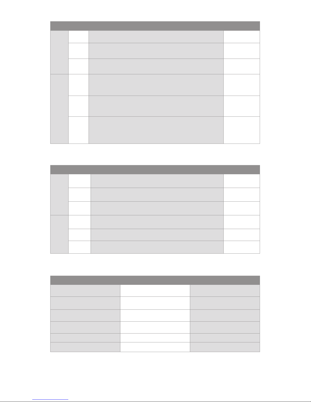
Zone Description Supported?
Gas 0 Explosive gas air mixture continuously present.
1 Explosive gas air mixture likely to occur in normal
operation.
2 Explosive gas air mixture not likely to occur, and if it does
it will only exist for a short time.
Dust 20 Explosive atmosphere in the form of a cloud of
combustible dust in air is continuously present, or for long
periods or frequently.
21 Explosive atmosphere in the form of a cloud of
combustible dust in air is likely to occur occasionally in
normal operation.
22 Explosive atmosphere in the form of a cloud of
combustible dust in air is not likely to occur in normal
operation, but if it does occur, will only persist for a short
period.
Group Definition Supported?
Gas IIA e.g. Propane
IIB e.g. Ethylene
IIC e.g. Hydrogen
Dust IIIA Combustible flyings
IIIB Non-conductive dusts
IIIC Conductive dusts
Table 1: Gas and Dust Zones in which the ExTemp may be used
Table 2: Gas and Dust Groups in which the ExTemp is suitable for use
Table 3: Gas ignition temperature classifications to which the ExTemp conforms
Gas Ignition Temperature Classification Supported?
450 °C T1
300 °C T2
200 °C T3
135 °C T4
100 °C T5 NO
85 °C T6 NO
Page 4
4
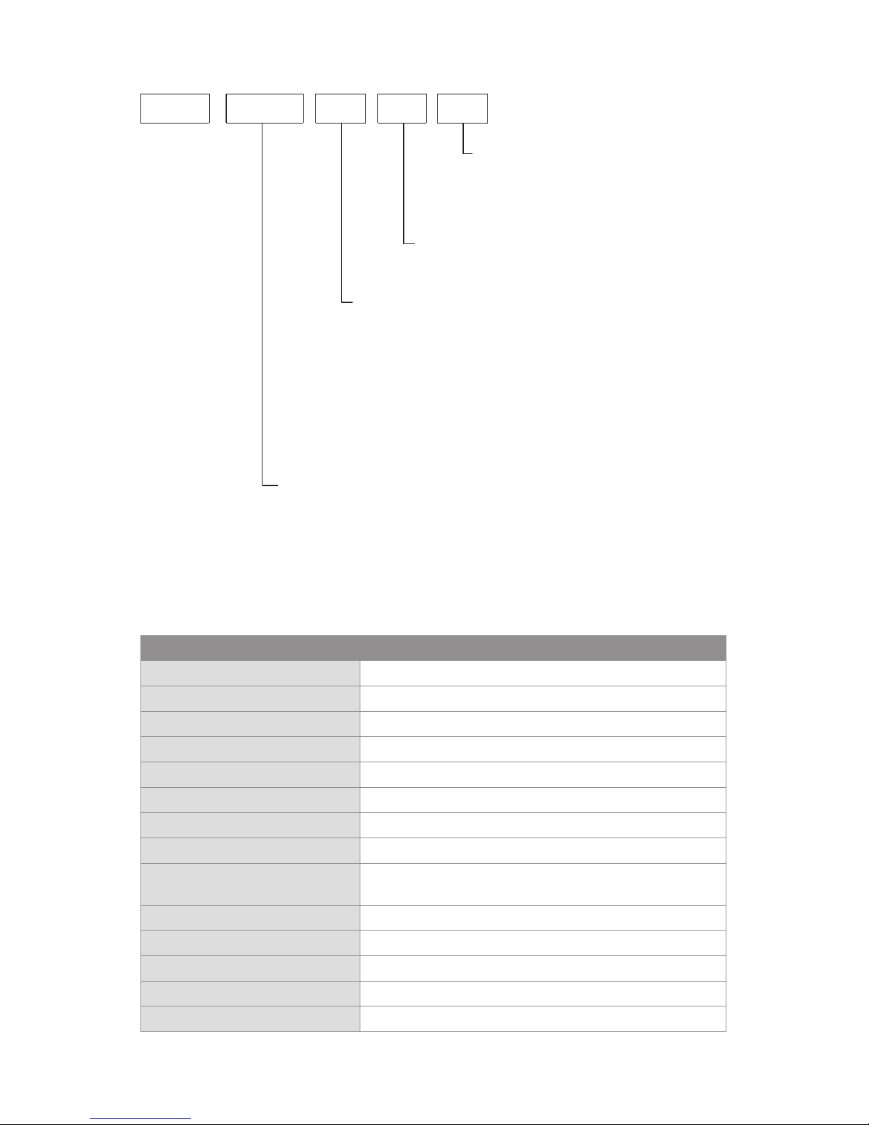
MODEL NUMBERS
SPECIFICATIONS
EX
----
FFF
CTT LL
Field of view
21 = 2:1 divergent optics
151 = 15:1 divergent optics
301 = 30:1 divergent optics
CF = Close focus optics
(Spot Ø 5 mm at distance 100 mm)
Temperature Range
LT = -20°C to 100°C
MT = 0°C to 250°C
HT = 0°C to 500°C
XT = 0°C to 1000°C
ST = Special temperature range
Temperature range may be re-scaled
between limits -20°C and 1000°C via optional
USB adapter and software
Cable Length
5 = 5 m
10 = 10 m
25 = 25 m
User Configurable
C = Configurable via optional USB adapter
General
Temperature Range -20°C to 1000°C (see table of Model Numbers)
Output 4 to 20 mA
Minimum Temperature Span 100°C
Maximum Temperature Span 1000°C
Field of View See table of Model Numbers
Accuracy ± 1°C or 1%, whichever is greater
Repeatability ± 0.5°C or 0.5%, whichever is greater
Emissivity Setting Range 0.20 to 1.00 (pre-set to 0.95)
Emissivity Setting Method User configurable via optional LCT Loop Configuration
Tool (USB adapter)
Response Time, t90 240 ms (90% response)
Spectral Range 8 to 14 μm
Supply Voltage 12 to 24 V DC ± 5%
Minimum Sensor Voltage 11.4 V DC
Maximum Current Draw 25 mA
Page 5
5
Mechanical
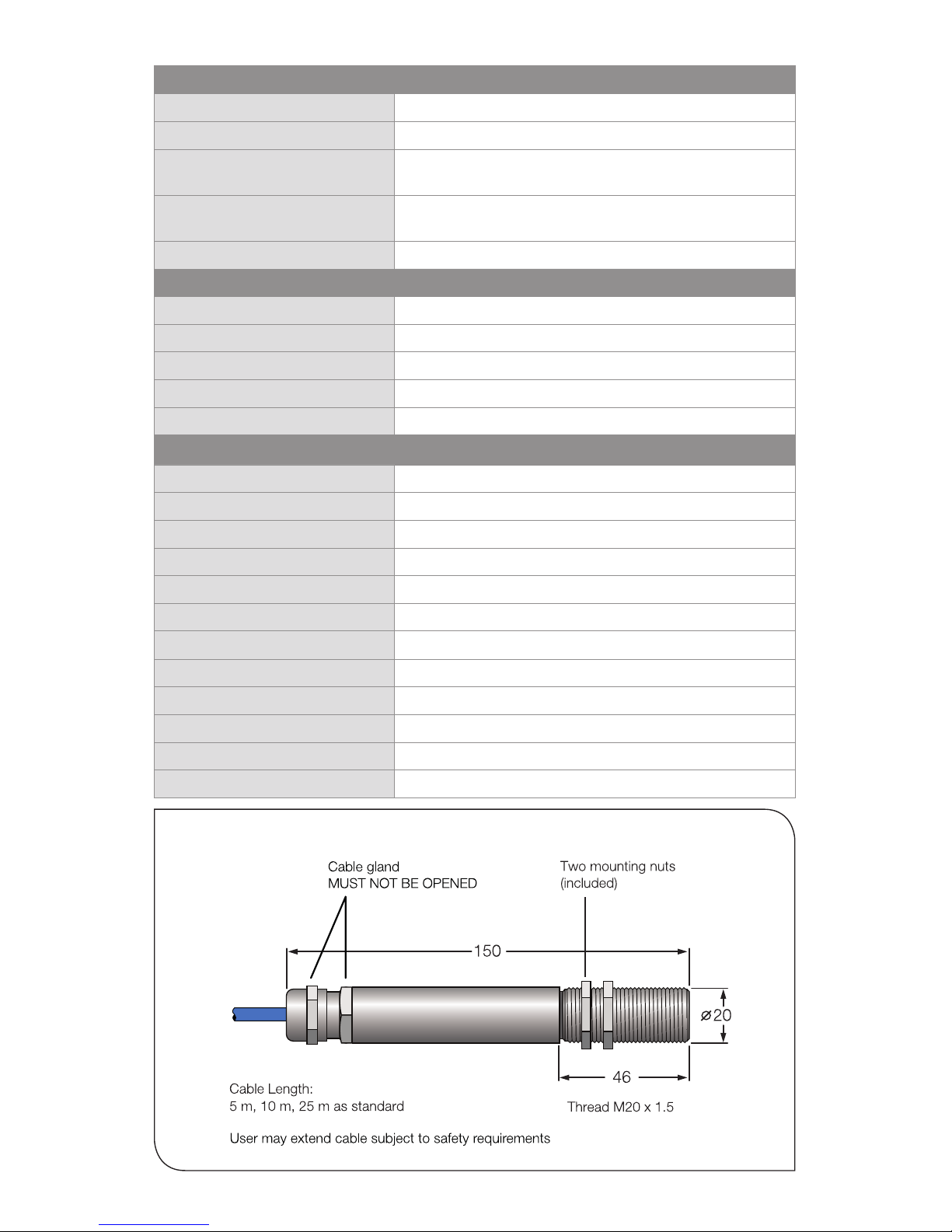
Construction Stainless Steel 316
Major Dimensions Ø 20 x length 150 mm (see Dimensions)
Mounting M20 x 1.5 mm thread, length 46 mm, supplied with two
mounting nuts
Cable Length Choice of 5 m, 10 m or 25 m factory-fitted. Contact
Calex for information about extending cable.
Weight with 5 m Cable 475 g
Environmental
Environmental Rating IP65 (NEMA 4)
Ambient Temperature Range 0°C to 70°C (Operating range)
Relative Humidity Max. 95% non-condensing
CE Marked Yes
RoHS Compliant Yes
Hazardous Area Classification
ATEX Classification Ex II 1GD
IECEx Classification (Gas) Ex ia IIC T4 Ga
IECEx Classification (Dust) Ex ia IIIC T135°C IP65 Da
Ambient Temperature Rating -20°C ≤ Ta ≤ 70°C
Maximum DC Input Voltage Ui = 28 V
Maximum Input Current Ii = 93 mA
Maximum Input Power Pi = 650 mW
Maximum Internal Capacitance Ci = 8 nF
Maximum Internal Inductance Li = 0 mH
ATEX Certificate Number CML 14ATEX2079
IECEx Certificate Number IECEx CML 14.0032
TIIS Certificate Number TC21097
DIMENSIONS (MM)
Page 6

6
ACCESSORIES
A range of accessories to suit different applications and industrial environments is available as
follows. These may be ordered at any time and added on-site:
• LCT Loop Configuration Tool (USB adapter)
• Fixed and adjustable mounting brackets
• Air purge collar
OPTIONS
The following options are available. Options are factory installed and must be ordered with
the sensor.
• Certificate of calibration
• Extended cable (25 m max. factor y-fitted; contct Calex for information about
extending the cable)
OPTICS
The below chart shows the measured spot diameter at the given distances from the sensing
head and assumes 90% energy. The sensor may be used at longer distances than shown
below, with a larger measured spot size.
INSTALLATION AND MAINTENANCE
The installation process consists of the following stages:
1 Preparation
2 Mechanical installation
3 Electrical installation
Please read the following sections thoroughly before proceeding with the installation.
11.0
0
Spot Dia.
(inches)
Spot Dia.
(mm)
Distance: Sensor to object (inches)
Distance: Sensor to object (mm)
61.9
111.9
0.5
2.4
4.4
0 4 8
100 200
D:S 2:1
-21
Distance: Sensor to object (inches)
Distance: Sensor to object (mm)
11.0
45.2
78.6
0.5
1.8
3.1
0 19.7 39.4
0 500 1000
Spot Dia.
(inches)
Spot Dia.
(mm)
D:S 15:1
-151
Distance: Sensor to object (inches)
Distance: Sensor to object (mm)
11.0
28.6
45.2
0.5
1.1
1.8
0 19.7 39.4
0 500 1000
Spot Dia.
(inches)
Spot Dia.
(mm)
D:S 30:1
-301
Spot Dia.
(inches)
Spot Dia.
(mm)
Distance: Sensor to object (inches)
Distance: Sensor to object (mm)
11.0
0.5
0
0
5.0
0.20
100
3.9
12.5
0.49
200
7.9
-CF
Page 7

7
Distance and Spot Size
Ensure the sensor is positioned
so that it can only detect infrared
radiation from the target.
The size of the area (spot size)
to be measured determines the
distance between the sensor and
the target. The spot size must
not be larger than the target.
The sensor should be mounted
so that the measured spot size is
smaller than the target.
We normally recommend the
target is at least twice the size
of the given measured spot for
maximum accuracy.
PREPARATION
Ambient Temperature
The sensor is designed to operate in ambient temperatures from 0°C to 70°C.
Avoid thermal shock. Allow 20 minutes for the unit to adjust to large changes in ambient
temperature.
Atmospheric Quality
Smoke, fumes or dust can contaminate the lens and cause errors in temperature
measurement. In these types of environment the air purge collar should be used to help keep
the lens clean.
Electrical Interference
To minimise electromagnetic interference or ‘noise’, the sensor should be mounted away from
motors, generators and such like.
Wiring
Check the distance between the sensor and the indicating/controlling device. If necessary,
the sensor can be ordered with a longer cable attached. Contact Calex for information about
extending the cable.
Power Supply
A suitable intrinsically safe barrier or isolator must be used. See Specifications for the supply
voltage, current and safety requirements.
MECHANICAL INSTALLATION
Mounting
All sensors come with a hard-wired cable and 2 mounting nuts. The sensor can be mounted
on brackets or cut outs of your own design, or you can use the fixed and adjustable mounting
bracket accessories, which are shown in the following diagram.
Note: The sensor must be connected to earth at one point, either the cable shield
termination or the sensor housing.
Page 8

8
MOUNTING BRACKETS
AIR PURGE COLLAR
The lens must be kept clean and dry for an accurate reading. The optional air purge collar is
used to keep dust, fumes, moisture, and other contaminants away from the lens. It must be
screwed on fully.
Air flows into the hose barb fitting and out of the front aperture. Air flow should be no more
than 5 to 15 litres/min. Clean or ‘instrument’ air is recommended.
Page 9

9
An alternative certified Intrinsically Safe isolator or safety barrier may be used. The
connections shown above are for the suggested isolator, model MTL 5541.
WIRE IDENTIFICATION - EXTEMP SENSOR
Identification tags are attached to the PWR+ and PWR- wires. If the tags are removed, the
wires can be identified by the numbers marked on the black insulation:
Wire Markings Wire Identity
1 PWR+
2 PWR-
Table 4: Wire Identification
CONFIGURATION
All models are configurable via the optional USB adapter (Loop Configuration Tool, model LCT)
and free CalexConfig configuration software.
The LCT has hook-type connectors and may be connected to the 4-20 mA loop as shown
above.
The LCT (USB adapter) is not certified for use in hazardous areas. It must
only be connected on the safe side of the safety barrier or isolator.
For information about installing and using the LCT, please see the LCT section of this manual.
ELECTRICAL INSTALLATION
Page 10

10
CONFIGURABLE PARAMETERS
The following settings can be configured via CalexConfig.
Configuration settings are password protected. To access the Settings menu, go to the Unlock
screen and enter the password. The default password is 1234.
Temperature Units
On the temperature display screen, click °C or °F to switch between temperature units.
Output Processing
Go to the Settings screen, then Output Processing.
• 4 to 20 mA Output Scale
Set the temperature range limits for the 4 to 20 mA output, between the limits of
-20°C and 1000°C.
The difference between the temperatures at 4 mA and at 20 mA must be at least
100°C. The temperature at 20 mA must be greater than the temperature at 4 mA.
Default setting: Depends on model, e.g. LT = -20°C to 100°C (see Model Numbers)
• Averaging Period
Set the time, in seconds, over which the measured temperature is averaged.
Note: averaging prevents the sensor from following rapid temperature changes.
Default setting: 0
• Peak/Valley Hold Processing
If required, hold processing can be applied by setting Hold Mode to “Peak” or “Valley”
and setting the hold period. This is useful if the temperature reading is interrupted by
gaps between moving objects, or by an obstruction.
Default setting : OFF
Emissivity and Compensation
From the Settings menu, go to Emissivity and Compensation.
• Emissivity Setting
Enter the emissivity of the target. Target emissivity can be determined experimentally,
or estimated using an emissivity table. For more information, contact Calex.
Default setting: 0.95
• Reflected Energy Compensation On/Off
If enabled, compensates for errors caused by reflected energy from hotter or colder
objects. This should generally be kept OFF in most applications.
Default setting: OFF
• Reflected Temperature
Enter the temperature of the surroundings of the target for Reflected Energy
Compensation. Changing this has no effect if Reflected Energy Compensation is OFF.
OPERATION
Once the sensor is in position, a suitable safety barrier or isolator is connected and
configured, and the appropriate power and cable connections are secure, the system is ready
for continuous operation by completing the following simple steps:
1 Turn on the power supply
2 Turn on the meter, chart recorder or controller
3 Read or monitor the temperature
Page 11

11
IMPORTANT
Be aware of the following when using the sensor:
• If the sensor is exposed to significant changes in ambient temperature (hot to cold,
or cold to hot), allow 20 minutes for the temperature to stabilise before taking or
recording measurements.
• Do not operate the sensor or configuration tool near large electromagnetic fields (e.g.
around arc welders, generators or induction heaters). Electromagnetic inter ference
can cause measurement errors.
• Wires must be connected only to the appropriate terminals.
• Do not damage the cable, as this could provide a path for moisture and vapour to
enter the sensor.
• Do not open the sensor housing. This will damage the sensor and invalidate the
warranty.
MAINTENANCE
Our customer service representatives are available for application assistance, calibration,
repair, and solutions to specific problems. Contact our Service Department before returning
any equipment. In many cases, problems can be solved over the telephone. If the sensor is
not performing as it should, try to match the symptom below to the problem. If the table does
not help, contact us for further advice.
LENS CLEANING
Keep the lens clean and dry at all times. Any foreign matter on the lens would affect
measurement accuracy. Blow off loose particles (if not using the air purge accessory) with an
air ‘puffer’.
If dust or condensation continuously forms on the lens, consider fitting an air purge collar.
TROUBLESHOOTING
Symptom Probable Cause Solution
No output No power to sensor Check power supply and wiring
Inaccurate
measured
temperature
Target too small for
sensor’s field of view
Ensure the sensor’s view is completely filled
by the target. Position the sensor closer to
the target to measure a smaller area.
Ensure the target is at least twice the size of
the given measured spot.
Target is a reflective
metal surface
Measure a non-reflective area, or paint or
coat a measurable area of the target to
make it non-reflective
Field of view
obstruction
Remove obstruction; ensure sensor has a
clear view of target
Dust or condensation
on lens
Ensure lens is clean and dry. Clean gently
with a soft lens cloth and water. If problem
recurs, consider using an air purge collar.
Incorrect wire
connections
Check wire markings - see Table 4: Wire
Identification
Output temperature
scale mismatch
Re-scale input temperature range on
measurement instrument to match sensor
Page 12

12
LOOP CONFIGURATION TOOL (LCT)
The Loop Configuration Tool model LCT is a configuration
adapter for ExTemp infrared temperature sensors.
It is designed to be connected to the 4 to 20 mA current loop on
the safe side of an Intrinsically Safe barrier or isolator, and to a
Windows PC via USB.
This manual describes how to connect the LCT and use it to
configure the sensor. For information on connecting and using
the sensor itself, please refer to the previous sections of this
manual.
WARNING
This device MUST NOT be used in hazardous areas. It is not cer tified for use
in explosive atmospheres and may only be connected on the safe side of a
suitable, certified Intrinsically Safe barrier or isolator.
Do not attempt to repair a faulty unit. Contact the vendor to arrange a return.
ELECTRICAL CONNECTION
Connect the device to the 4 to 20 mA measurement loop via the hook-type connectors. For
reliable communications, the total resistance RL on the 4 to 20 mA loop should be within the
range specified on the connection diagrams. You may need to connect a resistor in series with
the existing measurement instrumentation on the 4 to 20 mA loop to ensure this.
WIRE IDENTIFICATION - LCT
The LCT connectors are colour coded as follows:
Colour of Wire and Hook Connector Polarity
Red +
Black -
Measurement
instrumentation
LCT
PC with
software
Power supply
Hazardous Area
(All Zones IIC and IIIC)
Safe Area
(Non-Hazardous)
Intrinsically Safe
isolator or barrier
To the sensor
Page 13

13
EXAMPLE ISOLATOR: MODEL MTL5541
This isolator has an internal resistance of 220Ω. Two wiring configurations are possible,
depending on whether or not this internal resistance is used.
Configuration A: 400 Ω ≤ RL ≤ 800 Ω (not using the internal resistance)
11
12
R
L
LCT
-+-
+
4/20 mA
MTL5541
11
12
R
L
LCT
-
+
MTL5541
10
220 Ω
-
+
4/20 mA
+
2
R
L
LCT
-
+
MTL7706+
1
+
Earth pin
Configuration B: 180 Ω ≤ RL ≤ 580 Ω (using the internal resistance)
EXAMPLE BARRIER: MODEL MTL7706+
200 Ω ≤ RL ≤ 800 Ω
Page 14

14
SOFTWARE
The latest version of the software is available for download from the Calex website at the
following URL:
www.calex.co.uk/software
Install the software before connecting the LCT to a Windows PC. This will ensure the driver is
properly installed.
USING THE SOFTWARE
See Configurable Parameters and the Configuration Software diagram opposite.
If the Settings icon is greyed out, the software is locked. Unlock the software to allow access to
the Settings menu. The default password is 1234.
MAINTENANCE AND TROUBLESHOOTING
Our technical support engineers are available for application assistance, calibration, repair,
and solutions to specific problems. Contact our Service Department before returning any
equipment. In many cases, problems can be solved over the telephone. Contact us for further
advice.
GUARANTEE
Calex guarantees each instrument it manufactures to be free from defect in material and
workmanship under normal use and service for the period of two years from the date of
purchase. This guarantee extends only to the original buyer according to the Calex Terms and
Conditions of Sale.
Page 15

15
CONFIGURATION SOFTWARE
Unlock
Clear graph
Exit
Unlock Graph
Change Password
Settings
Apply (save and exit)
Select connected sensor
Emissivity &
Compensation
Temperature List
Temperature Display
4 to 20 mA
Output
Processing
Default
Password:
1234
Connection List
Page 16

Issue O - Aug 2018
Calex Electronics Limited
PO Box 2, Leighton Buzzard, Bedfordshire, England LU7 4AZ
Tel: +44 (0)1525 373178 Fax: +44 (0)1525 851319
Email: mail@calex.co.uk Online: www.calex.co.uk
 Loading...