

Page 1
he Construction Master Plus EZ (CMP EZ) is the newest in
T
Calculated Industries′ line of award-winning Construction Master
Plus construction-math calculators. The big difference between the
CMP EZ and the other models is that, in addition to many more built-in
calculations, the CMP EZ is a Prompting Calculator.
With a Prompting Calculator, you select a function and then scroll
through a series of prompts for quantities, measurements, placement,
materials and other possible inputs. After entering the inputs, you can
then
scroll through all the available calculations and solutions. You
can also change an input (or multiple inputs) and then re-solve the
problem, instantly seeing how the new entry changes calculations
without having to re-enter the entire problem.
The Construction Master Plus EZ has Basic and Advanced solutions
(lengths, angles, quantities, etc.) for these construction calculations:
● Rafters
● Hip/Valley Rafters
● Jack Rafters
● Stairs
Other solutions include
● Square-Ups, Areas and Volumes
● Circular
● Arcs
● Rake Walls
● Arch Studs
● Balusters ─ Cap Wall and Open Wall
● Elliptical Arches
● Crown Molding
● Compound Angles
● Polygons
● Spacing
● Material Calculations for Blocks, Drywall, Fencing, Footings,
Pavers, Roong, Studs, Tile and Grout
TABLE OF CONTENTS
GETTING STARTED
Key Denitions ..........................................................................................2
Basic Function Keys ..............................................................................2
Dimensional Function Keys ...................................................................2
Weight and Volume Function Keys ....................................................... 2
Miscellaneous Functions .......................................................................2
Construction and Prompting Keys .........................................................3
USING THE CONSTRUCTION MASTER PLUS EZ
Default Values ...........................................................................................3
Functions — U.S. Mode ........................................................................ 3
Functions — Metric Mode .....................................................................3
Materials — U.S. Mode ......................................................................... 4
Materials — Metric Mode ......................................................................4
Extras — U.S. Mode ..............................................................................4
Square-Up and LxWxH Functions ............................................................. 4
Square-Up .............................................................................................4
Extras — Metric Mode ........................................................................... 4
LxWxH ................................................................................................... 4
Rafter Function .......................................................................................... 5
Basic Rafters .........................................................................................5
Advanced Rafters .................................................................................. 5
Hip/Valley Rafter Function ......................................................................... 5
Basic Hip/Valley Rafters ........................................................................ 5
Advanced Hip/Valley Rafters .................................................................6
Advanced Function with Common Pitch ................................................6
Advanced Function with Irregular Pitch ................................................. 6
Jack Rafter Function .................................................................................6
Basic Jack Rafters .................................................................................6
Jack Rafters – Advanced Function ........................................................7
Stair Function ............................................................................................7
Basic Stairs ...........................................................................................8
.......................................................................................2
......................................... 3
ConstruCtion Master Plus eZ
1
Page 2
Advanced Stairs .................................................................................... 8
Circular Function .......................................................................................9
Rake Wall Function ...................................................................................9
Arc Function ............................................................................................10
Arch Stud Function .................................................................................. 10
Baluster Function .................................................................................... 11
Cap Wall .............................................................................................. 11
Open Wall ............................................................................................ 11
Materials Functions ................................................................................. 11
Blocks .................................................................................................. 11
Drywall .................................................................................................12
Fencing ................................................................................................12
Footings ...............................................................................................12
Pavers .................................................................................................13
Roong ................................................................................................13
Studs ................................................................................................... 13
Tile .......................................................................................................14
Extras ......................................................................................................14
Preference Settings ............................................................................. 14
Elliptical Arch Function ........................................................................15
Crown Molding Function ......................................................................15
Compound Angle Function .................................................................. 16
Polygon Function .................................................................................16
Spacing Function .................................................................................16
GettinG Started
KEY DEFINITIONS
Basic Function Keys
On/Clear Key – Turns on power. When not in a prompting
O
sequence, pressing once clears the last entry and what is
displayed. Pressing twice clears all non-permanent values.
Within a prompting input sequence, pressing once clears the
entry and leaves the prompt displayed. Pressing twice exits
the prompt function but does not clear non-permanent values.
A third press clears non-permanent values.
Within an output sequence, pressing once exits the prompt
function, but does not clear non-permanent values. Pressing
twice clears non-permanent values.
Off – Turns all power of f. Clears all non-permanent memory.
o
+-x ÷=
– 9 and
0
RR
CR
CM
Dimensional Function Keys
Arithmetic operation keys
Keys used for entering numbers.
.
Convert – Used with the dimensional keys to convert
C
between units or with other keys to access special functions.
Recall – Used with other keys to recall stored values
R
and settings.
Memory Clear – Clears Accumulative Memory and
displays total.
Store – Used for storing values.
Accumulative Memory – Adds displayed value to
M
Accumulative Memory.
M- – Subtracts displayed value from Accumulative Memory.
Yards – Identies entry as yards, with repeated presses
y
toggling bet ween linear, area and volume units.
Feet – Identies entry as Feet, with repeated presses
f
toggling bet ween linear, area and volume units. Also
used with
Repeated presses during conversions toggle between
fractional Feet-Inch and decimal Feet.
and / keys for entering Feet-Inch values.
i
Inch – Identies entry as Inches, with repeated presses
i
toggling bet ween linear, area and volume units. Entry
can be whole or decimal numbers. Also used with
entering fractional inch values (e.g.,
Repeated presses during conversions toggle between
fractional and decimal inches.
Fraction Bar – Used to enter fractions. Fractions can be
/
entered as proper (1/2, 1/8, 1/16) or improper (3/2, 9/8). If
the denominator (bottom) is not entered, the calculator′s
fractional accuracy setting is automatically used. Results are
always shown in typical building fractional format.
Meters – Identies entry as meters, with repeated presses
m
toggling bet ween linear, area and volume units. Converts
dimensional value to units of meters, with repeated presses
toggling bet ween meters and millimeters.
C7
C9
C8
C2
Weight and Volume Function Keys
C5
C4
C3
C6
C1
Miscellaneous Functions
C%
C0
CR0
C.
C=
C+
C-
Cx
C÷
Centimeters (cm) – Identies entry as centimeters, with
repeated presses toggling between linear, area and volume
units.
Millimeters (mm) – Identies entry as millimeters, with
repeated presses toggling between linear, area and
volume units.
Board Feet (Bd Ft) – Enters or converts cubic values to
Board Feet. One Board Foot is equal to 144 cubic inches.
Acre – Enters or converts a square value to Acres.
Weight per Volume (wt/vol) – Stores a new weight volume
as tons per cubic yard or other format as shown below.
Default value is 1.5 tons per cubic yard.
● Tons per cubic yard
● Pounds per cubic yard
● Pounds per cubic feet
Pounds (lbs) – Enters or converts a weight or volume value
to pounds.
Metric Tons (met tons) – Enters or converts a weight or
volume value to metric tons.
Tons – Enters or converts a weight or volume value to tons.
Kilograms (kg) – Enters or converts a weight or volume
value to kilograms.
Backspace Function – Used to delete entries one keystroke
<
at a time (unlike the
entry).
Percentage – Used to nd a given percentage of a number.
%
x2 – Squares the value on the display.
Total Cost (Cost) – Calculates total cost based on entered or
stored Unit Cost.
Unit Cost – Stores the Unit Cost for calculating the total cost.
To recall this setting, press
(no Unit Cost).
Degrees:Minutes:Seconds (dms◄►deg) – Converts
between D:M:S and decimal degree formats; repeated presses
will toggle between the two formats.
Square Root (√¯
number on the display.
Pi – Displays value of π (3.1415927).
Change Sign (+/–) – Toggle displayed value between
negative and positive value.
Clear All – Returns all stored values to the default settings.
Does not affect Preference Settings.
Reciprocal (1/x) – Finds the Reciprocal of a number
(e.g.,
8C÷ =
O
x) – Calculates the Square Root of the
0.125).
for
/
6f9i1/2
● Pounds per cubic inch
● Metric tons per cubic meter
● Kilograms per cubic meter
function, which deletes the entire
. Default is 0.00
R0
).
ConstruCtion Master Plus eZ
2
Page 3
Construction and Prompting Keys
Complete listings of required and optional entries and the resulting solutions are
in the Construction Examples section.
Square Up – Calculates the Square-Up (diagonal) length,
S
Area and Perimeter when Length and Width are entered.
CS
Cr
Ch
Cj
Cs
Cc
Ca
Cb
CN
Ce
LxWxH – Calculates Volume, Wall Surface Area, Wall +
Ceiling Area, Square- Up, Area and Perimeter when Length,
Width and Height are entered.
Rafter (Basic) – Calculates basic lengths and angles
r
for Rafters.
Rafter (Advanced) – Calculates basic lengths and angles for
Rafters.
Hip/Valley (Basic) – Calculates basic lengths and angles for
h
Regular and Irregular Hip/ Valley rafters.
Hip/Valley (Advanced) – Calculates advanced lengths and
angles for Regular and Irregular Hip/Valley rafters.
Jack Rafter (Basic) – Calculates basic lengths and angles for
j
Regular and Irregular Jack raf ters.
Jack Rafter (Advanced) – Calculates advanced lengths and
angles for Regular and Irregular Jack rafters.
Stair (Basic) – Calculates values for Stairs when Floor-to-
s
Floor Rise and/or Stair Run is entered.
Stair (Advanced) – Calculates values for Stairs, allowing
for Upper and Lower Flooring Thickness, Nosing Length and
Riser Thickness for additional calculations.
Circular – Calculates for Diameter, Radius, Perimeter or Area
c
when one of these values is entered. Enter Height and one of
the other four values to calculate Cones and Columns.
Rake Wall – Calculates various stud lengths for Rake Walls
with or without bases.
Arc – Calculates values for Chord Length, Arc Height, Radius,
a
Arc Length/Angle, and Arc Segment Area.
Arch Stud – Calculates Arch Stud lengths for Arched Walls.
Baluster – Calculates for Cap Wall Balusters, where all
b
baluster lengths are the same.
Open Baluster – Calculates for Open Wall Balusters, which
have different-length balusters on a tread.
Materials – Accesses functions for Blocks, Dr ywall, Fencing,
N
Footings, Pavers, Roong, Studs and Tile.
Extras – Accesses functions for Elliptical Arches, Crown
Molding, Compound Angles, Polygons and Spacing. Also
used to access Preferences for customizable settings (see
Preference Settings on page 17).
Up Arrow – Used to scroll up (or back) through prompts and
^
entries.
Down Arrow – Used to scroll down (or forward) through
v
prompts and entries.
Enter – Used to enter or accept values.
e
Solve – Used to skip the remaining entry prompts and proceed
to the rst available solution for the chosen function.
USinG the
ConStrUCtion MaSter PlUS eZ
The Construction Master Plus EZ is a Prompting Calculator. To use it
you simply select a function and then scroll through a series of prompts for
quantities, measurements, placement, materials and other possible inputs.
After entering the inputs, you can then scroll through all the available
calculations and solutions. You can also change an input (or multiple
inputs) and then re-solve the problem, instantly seeing how the new entry
changes calculations without having to re-enter the entire problem.
You can also use the
input prompts and go directly to the solution.
Ce
AUTO SHUT-OFF AND AUTO SHUTDOWN
The LCD display on your calculator is designed to shut off after 4 minutes
of non-use. If the display powers off, just press the
back on. All values are maintained. Your most recent entry will be displayed
and you can scroll through or continue to enter values for the same
calculation you were working on before the display shut off. After 4 hours
of non-use, the calculator will shut down and all temporary settings and
values are cleared.
U.S. AND METRIC MODES
The Construction Master Plus EZ can be used in either U.S. Mode (the
calculator’s default setting), which uses inches, or Metric Mode, which uses
millimeters, as a basis for entries and calculations. To change the Mode,
go to Preferences, using the Extras function (
DEFAULT VALUES
The table below shows the calculator’s U.S. and Metric Default Values.
Default Values can be changed by entering a new value. The new Default
Value will remain until you change it or reset it to zero. An All Clear
(
Roong calculations are based on 4' x 8' Sheathing Size.
Common Rafter
• Ridge Thickness 1-1/2"
• Rafter Width 7-1/4"
• Plate Width 3-1/2 "
Jack Rafter
Rake Wall
• O.C. Spacing 16"
• Top Plate Thickness 1-1/2"
Common Rafter
• Ridge Thickness 38 mm
• Rafter Width 200 mm
• Plate Width 1 0 0 m m
Jack Rafter
• O.C. Spacing 400 mm
• Rafter Thickness 38 mm
• Hip/V Thickness 38 mm
• Ridge Thickness 38 mm
Rake Wall
• O.C. Spacing 400 mm
• Top Plate Thickness 38 mm
) will reset values to the calculator’s Default Values.
Cx
Functions — U.S. Mode
• O.C. Spacing 16"
• Rafter Thickness 1-1/2"
• Hip/V Thickness 1-1/2"
• Ridge Thickness 1-1/2"
Functions — Metric Mode
(Solve) function to skip any remaining
key to power it
O
CN
Baluster/Open Baluster
• Maximum Spacing 4"
Hip/ Valley
• Ridge Thickness 1-1/2"
Stairs
• Target Riser Height 7-1/2"
• Target Tread Width 10"
• Top Floor Thickness 10"
• Headroom Height 80"
Arch Studs
• O.C. Spacing 16"
• Location: 1 = Outside
Baluster/Open Baluster
• Maximum Spacing 100 mm
Hip/ Valley
• Ridge Thickness 38 mm
Stairs
• Target Riser Height 190 mm
• Target Tread Width 250 mm
• Top Floor Thickness 250 mm
• Headroom Height 2 1 0 0 m m
Arch Studs
• O.C. Spacing 400 mm
• Location: 1 = Outside
).
ConstruCtion Master Plus eZ
3
Page 4
Materials — U.S. Mode
Blocks
• Block Height 8″
• Block Length 16″
• Waste Factor 5%
Drywall Sheets
• Include Ceiling: 1 = Yes
• Sheet Length 8′
• Sheet Width 4′
• Waste Factor 5%
Fencing
• Number of Rails 2
• Maximum Post Spacing 96″
• Post Width 3-1/2′
Footings
• Footing Area 264 Sq Inches
• Waste Factor 5%
Pavers
• Paver Length 8"
• Paver Width 4"
• Waste Factor 5%
Materials — Metric Mode
Blocks
• Block Height 215 mm
• Block Length 440 mm
• Waste Factor 5%
Drywall Sheets
• Include Ceiling: 1 = Yes
• Sheet Length 2400 mm
• Sheet Width 1200 mm
• Waste Factor 5%
Fencing
• Number of Rails 2
Maximum
•
Spacing
• Post Width 69 mm
Footings
• Footing Area 0.2 sq m
• Waste Factor 5%
Pavers
• Paver Length 215 mm
• Paver Length 102.5 mm
• Waste Factor 5%
Extras — U.S. Mode Extras — Metric Mode
Elliptical Arch
• O.C. Spacing 16″
• Position 1 = Outside
Crown Molding
• Corner Angle 90°
• Spring Angle 45°
Spacing
• Object Width 1 - 1 / 2 ″
• End Position 1 = Beginning
• Mark Position 2 = On-Center
Post
2.4 m
Roong
• Waste Factor 5%
• Number of Nails
per Shingle
• Length of Nail 1-1/4″
• Number of Pieces
per Bundle
• Number of Bundles
per Square
Drywall Sheets
• Include Ceiling: 1 = Yes
• Sheet Length 8′
• Sheet Width 4′
• Waste Factor 5%
Studs
• O.C. Spacing 16″
• Waste Factor 5%
Tile
• Grout Width 1/8″
• Tile Thickness 1/4″
• Waste Factor 5%
• Backer Board Size 3′ x 4′
Roong
• Sheathing Size
• Number of Nails per
Shingle
• Length of Nail 30 mm
• Number of Pieces
per Bundle
• Number of Bundles
per Square
• Waste Factor 5%
Studs
• O.C. Spacing 400 mm
• Waste Factor 5%
Tile
• Grout Width 2 mm
• Tile Thickness 7 mm
• Waste Factor 5%
• Backer Board Size 1200 mm
Elliptical Arch
• O.C. Spacing 400 mm
• Position 1 = Outside
Crown Molding
• Corner Angle 90°
• Spring Angle 45°
Spacing
• Object Width 38 mm
• End Position 1 = Beginning
• Mark Position 2 = On-Center
21
1200 mm x
2400 mm
21
CONSTRUCTION EXAMPLES
For each of the functions shown in the User’s Guide there is a box showing
all of the required entries, optional entries and possible solutions for
4
3
that function. You can also quickly see the prompts for entries and possible
solutions for each function on the calculator by accessing the function and
then scrolling through the prompts and solutions, with repeated presses of
the
Note: After scrolling through all your entries and solutions, the calculator
will display REPEAT briey before returning to the rst input prompt. You
can then scroll through and view (or change) entries and solutions. It’s
recommended that you allow the REPEAT message to disappear before
continuing to scroll through the function. Not doing so will skip the rst
input prompt.
key, the ^ key or the v key.
e
SQUARE-UP AND LxWxH FUNCTIONS
Square-Up
Required Entries Solutions
Length
Width
Enter a 15′ 8" Length and a 12′ 6" Width:
1. Clear Calculator:
Square-Up
Area
Perimeter
OOO
2. Start Square- Up function:
S
3. Enter 15′ 8" Length:
15f8ie
4
4. Enter 12′ 6" Width and solve for Square- Up:
12f6ie
SQUARE-UP
AREA
3
e
PERIMETER
e
LxWxH
Entries Solutions
Length
Width
Height
Enter a 15′ 8" Length, 12′ 6" Width and 4" Height:
1. Clear Calculator:
Volu me
Vertical Surface Area
Vertical + LxW Surface Area
Square-Up
LxW Area
Perimeter
20 FEET 0-1/2 INCH
195.83333 SQ FEET
56 FEET 4 INCH
OOO
2. Start Length x Width x Height function:
CS
3. Enter 15′ 8" Length:
15f8ie
4. Enter 12′ 6" Width:
12f6ie
5. Enter 4" Height and solve for L x W x H:
4ie
VOLUME
VERTICAL SURFACE AREA
e
VERTICAL + LxW AREA
e
SQUARE-UP
e
LxW AREA
e
PERIMETER
e
65.277778 CU FEET
18.777778 SQ FEET
214.61111 SQ FEET
20 FEET 0-1/2 INCH
195.83333 SQ FEET
56 FEET 4 INCH
ConstruCtion Master Plus eZ
4
Page 5

RAFTER FUNCTION
Basic Rafters
Required Entries Possible Solutions
Two of these required:
• Pitch
• Run (or Span)
• Rise
• Common Rafter Length
Solve for Basic Rafters using an 8" Pitch and 12' Run:
1. Clear Calculator:
Common Raf ter Length
Level Angle
Pitch
Plumb Angle
Run
Rise
OOO
2. Start Rafter function:
r
3. Enter 8" Pitch:
8ie
4. Enter 12′ Run and solve for Basic Rafters:
12fe
DIAGONAL
PLUMB ANGLE
e
LEVEL ANGLE
e
RISE
e
Advanced Rafters
Required Entries Possible Solutions
Two of these required:
• Pitch
• Run (or Span)
• Rise
• Common Rafter Length
Optional Entries
Horizontal Overhang
Total Fascia Thickness
Ridge Thickness
• Default value: 1-1/2"
Rafter Width
• Default value: 7-1/4"
Top Plate Width
• Default value: 3-1/2"
HAP*
* Height Above Plate. If a Top Plate value is shown when you want to enter a HAP, clear
the Top Plate value by pressing either
HAP entr y prompt and enter the desired value.
**Tail Length and Total Rafter Length shown only when Horizontal Overhang is entered.
Enter an 8" Pitch, a 12′ Run, an 18" Overhang and 2-1/4" Total
Fascia Thickness:
1. Clear Calculator:
Common Raf ter Length
Common Tail Length**
Total Rafter Length**
Plumb Angle
Level Angle
Seat Cut
Standard 2/3 HAP
Full Bearing HAP
Pitch
Run
Rise
or 0. Then, press e to move to the
O
14 FEET 5-1/16 INCH
33.69 °
56.31 °
8 FEET 0 INCH
Cx
2. Start Advanced Rafter function:
Cr
3. Enter 8" Pitch:
8ie
4. Enter 12′ Run:
12fe
5. Enter 18" Overhang:
18ie
6. Enter 2-1/4" Total Fascia Thickness:
2i1/4e
7. Accept 1-1/2" default value for Ridge Thickness:
e
8. Accept 7-1/4" default value for Rafter Width:
e
9. Accept 3 -1/2" default value for Top Plate Width and solve for Rafters:
e
COMMON RAFTER LNTH
TAIL LENGTH
e
TOTAL RAFTER LNTH
e
PLUMB ANGLE
e
LEVEL ANGLE
e
STANDARD 2/3 HAP
e
FULL BEARING HAP
e
RISE
e
HIP/VALLEY RAFTER FUNCTION
Basic Hip/Valley Rafters
Required Entries Possible Solutions
Two of the rst three required:
•
Common Pitch
•
Run (or Span)
•
Rise
Optional Entries
Irregular Pitch
Find the Hip/Valley Rafter Lengths and Angles using an 8" Common Pitch and
a 12′ Run:
1. Clear Calculator:
Hip/Valley Length
Plumb Angle
Level Angle
Common Cheek Angle
Irregular Cheek Angle
14 FEET 4-3/16 INCH
19-3/8 INCH
15 FEET 11- 9/16 INCH
33.69°
56.31°
5- 13/16 INCH
6-3/8 INCH
8 FEET 0 INCH
OOO
2. Start Basic Hip/Valley function:
h
3. Enter 8" Common Pitch:
8ie
4. Enter 12′ Run:
12fe
5. No entr y for Irregular Pitch (Common Pitch used). Solve for
Hip/ Valley values:
HIP/VALLEY LNTH
e
PLUMB ANGLE
e
LEVEL ANGLE
e
COMMON CHEEK ANGL
e
Find the Hip/Valley Rafter Lengths and Angles using an 8" Common Pitch, an 8′
Run and an Irregular Pitch of 10":
1. Clear Calculator:
18 FEET 9-1/8 INCH
25.24°
64.76°
45.00°
OOO
2. Start Basic Hip/Valley function:
h
3. Enter 8" Common Pitch:
8ie
4. Enter 8′ Run:
8fe
5. Enter 10" Irregular Pitch and solve for Hip/Valley values:
10ie
HIP/VALLEY LNTH
PLUMB ANGLE
e
LEVEL ANGLE
e
11 FEET 6-5/8 INCH
27.50°
62.50°
ConstruCtion Master Plus eZ
5
Page 6

COMMON CHEEK ANGL
e
IRREGULAR CHEEK ANGL
e
Advanced Hip/Valley Rafters
Required Entries Possible Solutions
Two of the rst three required:
•
Common Pitch
•
Run (or Span)
•
Rise
Optional Entries
Irregular Pitch
Horizontal Overhang
Total Fascia Thickness
Ridge Thickness
• Default value: 1-1/2"
* Tail Length shown only when Horizontal Overhang is entered.
Advanced Function with Common Pitch
Find Hip/Valley Lengths and Angles using an 8" Common Pitch, a 12′ Run, an
18" Horizontal Overhang and 2-1/4" Total Fascia Thickness:
1. Clear Calculator:
Total Hip/Valley Length
Hip/Valley Tail Length*
Plumb Angle
Level Angle
Common and Irregular
• Cheek Angle
• Backing Angle
• Sheathing Angle
• Plan Angle
38.66°
51.34°
OOO
2. Start Advanced Hip/Valley function:
Ch
3. Enter 8" Common Pitch:
8ie
4. Enter 12′ Run:
12fe
5. No Irregular Pitch (Common Pitch used):
e
6. Enter 18" Overhang*:
18ie
7. Enter 2-1/4" Total Fascia Thickness*:
2i1/4e
8. Accept 1-1/2" default value for Ridge Thickness* and solve for Hip/Valley:
TOTAL HIP/VALLEY LNTH
e
H/V RAFTER TAIL LNTH
e
PLUMB ANGLE
e
LEVEL ANGLE
e
COMMON CHEEK ANGLE
e
COMMON BACKING ANGL
e
COMMON SHEATHING ANGL
e
COMMON PLAN ANGL
e
* If the desired value is already displayed, there′s no need to re- enter it. Just press e
to accept it. The value you store will remain unchanged until you modify it or reset the
calculator.
Optional Entries only: If you don′t want to include an optional entry in your calculation,
simply clear it by entering
Advanced Function with Irregular Pitch
Find Hip/Valley Lengths and Angles using an 8 " Common Pitch, a 12′ Run, a
10" Irregular Pitch, an 18" Overhang and 2-1/4" Total Fascia Thickness:
1. Clear Calculator:
0e
.
20 FEET 9-7/8 INCH
25-7/8 INCH
25.24°
64.76°
45.00°
23.09°
50.24°
45.00°
OOO
2. Start Advanced Hip/Valley function:
Ch
3. Enter 8" Common Pitch:
8ie
4. Enter 12′ Run:
12fe
5. Enter 10" Irregular Pitch:
10ie
6. Enter 18" Overhang*:
18ie
7. Enter 2-1/4" Total Fascia Thickness*:
2i1/4e
8. Accept 1-1/2" Ridge Thickness* and solve for Hip/Valley:
TOTAL HIP/VALLEY LNTH
e
H/V RAFTER TAIL LNTH
e
PLUMB ANGLE
e
LEVEL ANGLE
e
COMMON CHEEK ANGL
e
IRREGULAR CHEEK ANGL
e
COMMON BACKING ANGL
e
IRREG BACKING ANGL
e
COMMON SHEATHING ANGL
e
IRREG SHEATHING ANGL
e
COMMON PLAN ANGL
e
IRREGULAR PLAN ANGL
e
* If the desired value is already displayed, there′s no need to re- enter it. Just press
to accept it. The value you store will remain unchanged until you modify it or
e
reset the calculator.
Optional Entries only: If you don′t want to include an optional entry in your calculation,
simply clear it by entering
0e
.
19 FEET 2– 9/16 INCH
23-3/4 INCH
27.50°
62.50°
38.66°
51.34°
20.27°
29.99°
56.35°
46.16°
51.34°
38.66°
JACK RAFTER FUNCTION
Basic Jack Rafters
Required Entries Possible Solutions
Two of the rst three required:
• Common Pitch
• Run (or Span)
• Rise
On-Center Spacing
• Default value: 16"
Optional Entries
Irregular Pitch
*On- Center Spacing is also a possible solution that displays when both of the following
are true: 1) Common and Irregular Pitches are not equal and 2) Jack Alignment
Preference is set to MAT E, rather than ON-CENTER.
Find the Jack Rafter Lengths and Angles using an 8" Common Pitch and a
6′ Run:
1. Clear Calculator:
Common and Irregular
• Jack On-center Spacing*
• Offset Length
• Rafter Length
• Jack Rafter Lengths
• Plumb Angle
• Level Angle
• Cheek Angle
OOO
2. Start Jack Rafter function:
j
3. Enter 8" Common Pitch:
8ie
4. Enter 6′ Run:
6fe
5. No entr y for Irregular Pitch (Common Pitch used):
e
6. Accept default On-Center Spacing (16") and solve for Jack Rafters:
e
COMMON OFFSET LNTH 19-1/4 INCH
COMMON RAFTER LNTH 7 FEET 2-9/16 INCH
e
ConstruCtion Master Plus eZ
6
Page 7
JACK RAFTER C-Ø1
e
JACK RAFTER C-Ø2
e
JACK RAFTER C-Ø3
e
JACK RAFTER C-Ø4
e
COMMON PLUMB ANGL
e
COMMON LEVEL ANGL
e
COMMON CHEEK ANGL
e
Find the Jack Rafter Lengths and Angles using a 6′ Run, a 4′ Rise and a 10″
Irregular Pitch:
1. Clear Calculator:
5 FEET 7-5/16 INCH
4 FEET 0-1/16 INCH
2 FEET 4-7/8 INCH
0 FEET 9-5/8 INCH
33.69°
56.31°
45.00°
OOO
2. Start Jack Rafter function:
j
3. No Common Pitch:
e
4. Enter 6′ Run:
6fe
5. Enter 4′ Rise:
4fe
6. Enter 10" Irregular Pitch:
10ie
7. Accept default On-Center Spacing (16") and solve for Jack Raf ters:
e
COMMON OFFSET LNTH
COMMON RAFTER LNTH
e
JACK RAFTER C-Ø1
e
JACK RAFTER C-Ø2
e
JACK RAFTER C-Ø3
e
COMMON PLUMB ANGL
e
COMMON LEVEL ANGL
e
COMMON CHEEK ANGL
e
IRREGULAR OFFSET LNTH
e
IRREGULAR RAFTER LNTH
e
IR JACK RAFTER I-Ø1
e
IR JACK RAFTER I-Ø2
e
IR JACK RAFTER I-Ø3
e
IR JACK RAFTER I-Ø4
e
IRREGULAR PLUMB ANGL
e
IRREGULAR LEVEL ANGL
e
IRREGULAR CHEEK ANGL
e
Jack Rafters – Advanced Function
Required Entries Possible Solutions
Two of the rst three required:
• Pitch
• Run (or Span)
• Rise
On-C enter Spacing*
• Default value: 16"
Optional Entries
Irregular Pitch
Horizontal Overhang
Total Fascia Thickness
Common Raf ter Thickness**
Hip/Valley Thickness**
Ridge Thickness**
Common and Irregular
• Jack On-center Spacing*
• Offset Length
• Rafter Length
• Jack Rafter Lengths
• Plumb Angle
• Level Angle
• Cheek Angle
24-1/16 INCH
7 FEET 2-9/16 INCH
5 FEET 2-1/2 INCH
3 FEET 2-7/16 INCH
1 FEET 2-7/16 INCH
33.69°
56.31°
51.34°
16- 11/16 INCH
6 FEET 3 INCH
4 FEET 10-5/16 INCH
3 FEET 5- 5/8 INCH
2 FEET 1 INCH
0 FEET 8-5/16 INCH
39.81°
50.19°
38.66 °
* Default value: 1-1/2"
** On- center Spacing is also a possible solution that displays when both of the following
are true: 1) Common and Irregular Pitches are not equal and 2) Jack Alignment
Preference is set to MAT E, rather than ON-CENTER.
** Tail Lengths shown only when Horizontal Overhang is entered.
Find the Jack Rafter Lengths and Angles using an 8" Pitch, a 6′ Run, an 18"
Horizontal Overhang and the default values shown above:
1. Clear Calculator:
Cx
2. Start Advanced Jack Rafter function:
Cj
3. Enter 8" Common Pitch:
8ie
4. Enter 6′ Run:
6fe
5. No Irregular Pitch (Common Pitch used):
e
6. Accept default On-Center Spacing (16"):
e
7. Enter 18" Overhang Run:
18ie
8. No Total Fascia Thickness:
(Enter 0 if a value is displayed)
e
9. Accept 1-1/2" default Rafter Thickness:
e
10. Accept 1-1/2" default Hip/ Valley Thickness:
e
11. Accept 1-1/2" default Ridge Thickness and solve for Jack Rafters:
e
COMMON OFFSET LNTH 19-1/4 INCH
COMMON TAIL LNTH
e
COMMON RAFTER LNTH
e
JACK RAFTER C-Ø1
e
JACK RAFTER C-Ø2
e
JACK RAFTER C-Ø3
e
JACK RAFTER C-Ø4
e
JACK RAFTER C-Ø5
e
COMMON PLUMB ANGL
e
COMMON LEVEL ANGL
e
COMMON CHEEK ANGL
e
5 FEET 8-13/16 INCH
STAIR FUNCTION
Note: Within Preferences, there is a setting for Riser Height that
determines which type of calculation will be used. The default is Target
Riser Height.
• Target Riser Height: Use this setting to get a stair calculation that will get as
close to the stored Riser Height as possible. The calculated Actual Riser Height
will either be shorter or taller than the Target Riser Height.
• Maximum Riser Height: This is used when local building codes prohibit risers
greater than this value. The calculated Actual Riser Height will not exceed the
Maximum Riser Height.
19-1/4 INCH
21-5/8 INCH
8 FEET 11-1/4 INCH
7 FEET 4-1/16 INCH
4 FEET 1-9/16 INCH
2 FEET 6-3/8 INCH
0 FEET 11-1/8 INCH
33.69°
56.31°
45.00°
ConstruCtion Master Plus eZ
7
Page 8

Basic Stairs
Required Entries Possible Solutions
One of these two required:
• Floor-to- Floor Rise
• Stair Run
Target/Max Riser Height
• Default value: 7-1/2"
Target Tread Width
• Default value: 10"
Top Floor Thickness
• Default value: 10"
Headroom Height
• Default value: 80"
Optional Entries
None
* A warning sign appears on the display when the calculated Tread Width is
less than the stored Tread Width or when the calculated Riser Height exceeds
the stored Riser Height.
** A warning sign
the Target Riser/Tread ratio.
With Preference Setting set to Target Riser Height, use default values and
solve for Basic Stairs with a 9′ 11" Floor-to-Floor Rise:
1. Clear Calculator:
appears if the actual Inclination Angle is 10% greater than
Number of Risers
Actual Riser Height*
Resulting Riser Offset
Number of Treads
Actual Tread Width*
Resulting Tread Offset
Minimum Stairwell Opening
Stringer Length
Inclination Angle**
Stair Run
Stair Rise
OOO
2. Start Basic Stair function:
s
3. Enter 9′ 11″ Floor-to -Floor Rise:
9f11ie
4. Accept default 7-1/2" Target Riser Height:
e
5. No Stair Run:
e
6. Accept default 10" Target Tread Width:
e
7. Accept default 10" Top Floor Thickness:
e
8. Accept default 80" Headroom Height and solve for Basic Stairs:
e
NUMBER OF RISERS
ACTUAL RISER HGHT.
e
RISER OFFSET +/-
e
NUMBER OF TREADS
e
ACTUAL TREAD WDTH
e
TREAD OFFSET
e
MIN STAIRWELL OPEN
e
STRINGER LENGTH
e
INCLINE ANGLE
e
STAIR RUN
e
Change Preference Setting to Maximum Riser Height and solve for Basic
Stairs with a 10′ 1" Floor-to-Floor Rise and a Stair Run of 15′ 5":
1. Clear Calculator:
15 FEET 6-15/16 INCH
7-7/16 INCH
10 FEET 1 INCH
12 FEET 6 INCH
16.
0 INCH
15.
10 INCH
+/- 0 INCH
36.64°
OOO
2. Start Basic Stair function:
s
3. Enter 10′ 1" Floor-to-Floor Rise:
10f1ie
4. Accept default 7-1/2" Max Riser Height:
e
5. Enter 15′ 5" Stair Run:
15f5ie
6. Accept default 10" Top Floor Thickness:
e
7. Accept default 80" Headroom Height and solve for Basic Stairs:
e
NUMBER OF RISERS
ACTUAL RISER HGHT.
e
RISER OFFSET +/-
e
NUMBER OF TREADS
e
ACTUAL TREAD WDTH
e
TREAD OFFSET
e
MIN STAIRWELL OPEN
e
STRINGER LENGTH
e
INCLINE ANGLE
e
Advanced Stairs
See Diagrams on page 23 ►
Required Entries Possible Solutions
One of these two required:
• Floor-to- Floor Rise
• Stair Run
Target/Max Riser Height
• Default value: 7-1/2"
Target Tread Width
• Default value: 10"
Top Floor Thickness
• Default value: 10"
Headroom Height
• Default value: 80"
Optional Entries
Upper Flooring Thickness
Lower Flooring Thickness
Nosing Length
Riser Thickness
* A warning sign appears on the display when the calculated Tread Width
is less than the stored Tread Width vor when the calculated Riser Height
exceeds the stored Riser Height ^.
** A warning sign
the Target Riser/Tread ratio.
*** Finished Stair Run value is shown only if Nosing Length or Riser Thickness
is entered.
With Preference Setting set to Target Riser Height, use default values and
solve for Advanced Stairs with a 9′ 11" Floor-to-Floor Rise, 3/4" Upper
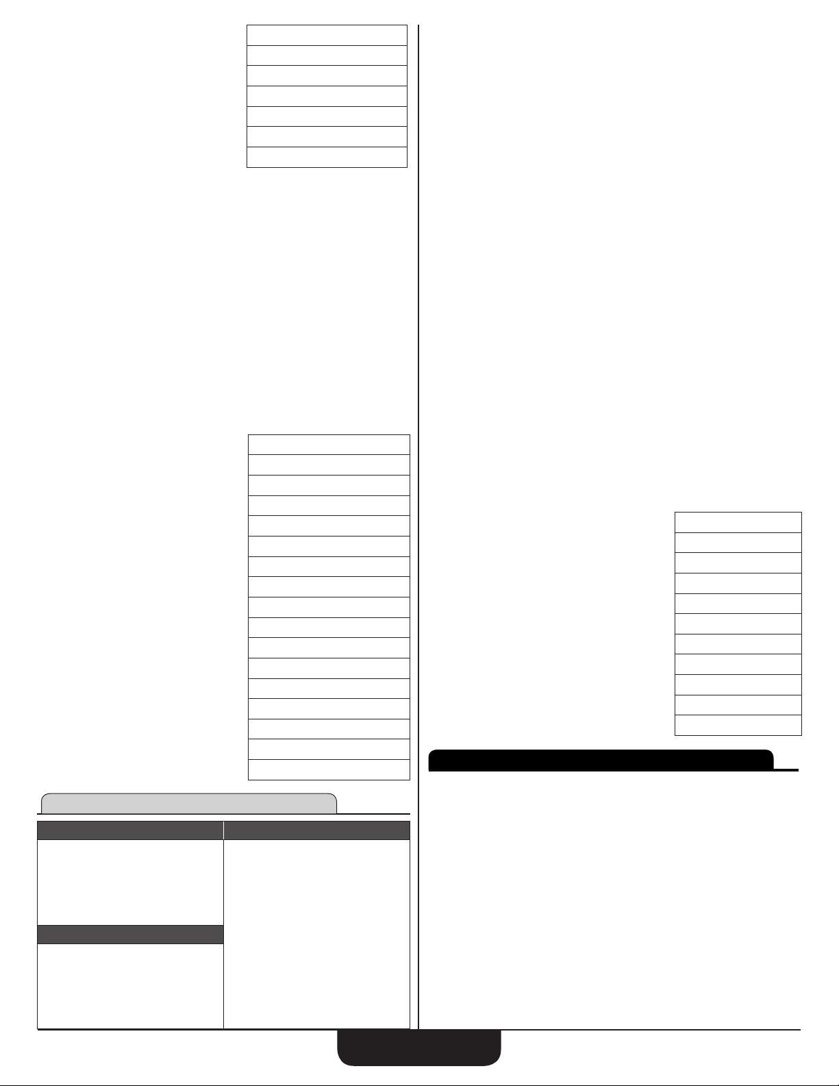
Flooring Thickness, 1-1/4" Lower Flooring Thickness, Nosing Length of 1/2"
and Riser Thickness of 3/4":
1. Clear Calculator:
appears if the actual Inclination Angle is 10% greater than
Net Floor-to-Floor Height
Number of Risers
Actual Riser Height*
Number of Treads
Actual Tread Width*
Minimum Stairwell Opening
Stringer Length
Inclination Angle**
Rough Stair Run
Finished Stair Run***
Toe Positions
11-9/16 INCH
12 FEET 2-1/16 INCH
18 FEET 1-5/16 INCH
17.
7-1/8 INCH
0-1/8 INCH
16.
+/- 0 INCH
31.64°
OOO
2. Start Advanced Stair function:
Cs
3. Enter 9′ 11" Floor-to -Floor Rise:
9f11ie
4. Accept default 7-1/2" Target Riser Height:
e
5. No Stair Run:
e
6. Accept default 10" Target Tread Width
e
7. Accept default 10" Top Floor Thickness:
e
ConstruCtion Master Plus eZ
8
Page 9
8. Accept default 80" Headroom Height:
e
9. Enter 3/4" Upper Flooring Thickness:
3/ 4ie
10. Enter 1-1/4" Lower Flooring Thickness:
1i1/4e
11. Enter 1/2" Nosing Length:
1/2e
12. Enter 3/4" Riser Thickness and solve for Advanced Stairs:
3/ 4e
NET FLOOR-TO-FLOOR RISE 9 FEET 10-1/2 INCH
NUMBER OF RISERS 16.
e
ACTUAL RISER HGHT 7-7/16 INCH
e
NUMBER OF
e
TREADS
ACTUAL TREAD WDTH 10 INCH
e
MIN STAIRWELL OPEN 10 FEET 3-3/16 INCH
e
STRINGER LENGTH 16 FEET 7-1/8 INCH
e
INCLINE ANGLE 36.52°
e
ROUGH STAIR RUN 12 FEET 6 INCH
e
FINISHED STAIR RUN 12 FEET 7-1/4 INCH
e
TOE POSITION 01 1 FEET 0-7/16 INCH
e
Continued presses of
TOE POSITION LAST
e
Example using Solve function:
Using default values (including 7-1/2" Target Riser Height), solve for
Advanced Stairs with a 10' 1" Floor-to-Floor Rise and a Stair Run of 15' 5":
1. Clear Calculator:
will show all Toe Positions.
e
16 FEET 7-1/8 INCH
15.
OOO
2. Start Advanced Stair function:
Cs
3. Enter 10′ 1" Floor-to-Floor Rise:
10f1ie
4. Accept default 7-1/2" Target Riser Height:
e
5. Enter 15′ 5" Stair Run and solve for Advanced Stairs:
15f5iCe
NET FLOOR-TO-FLOOR RISE
NUMBER OF RISERS
e
ACTUAL RISER HGHT
*
e
NUMBER OF TREADS
e
ACTUAL TREAD WDTH
e
MIN STAIRWELL OPEN
e
STRINGER LENGTH
e
INCLINE ANGLE
e
ROUGH STAIR RUN
e
TOE POSITION 01
e
Continued presses of
TOE POSITION LAST
e
*The
in the display indicates the Actual Riser Height exceeds the stored
Target Riser Height (Default value: 7-1/2").
will show all Toe Positions.
e
10 FEET 1 INCH
16.
7-9/16 INCH
15.
12-5/16 INCH
12 FEET 2-3/4 INCH
19 FEET 3-1/2 INCH
31.52 °
15 FEET 5 INCH
1 FEET 2-7/16 INCH
19 FEET 3-1/2 INCH
CIRCULAR FUNCTION
Required Entries Possible Solutions
Enter one of these:
• Diameter
• Radius
• Perimeter
• Area
Optional Entries
Height
If one value is known – Diameter, Radius, Perimeter or Area – the other
three are calculated and stored. Height is required for Cone and Column
calculations.
The Diameter of a circle is 15 Feet 8 Inches. Find the Radius, Perimeter
and Area:
1. Clear Calculator:
Column Volume
Column Sur face Area
Cone Volume
Cone Surface Area
OOO
2. Start Circular function:
c
3. Enter 15′ 8" Diameter and solve for Circular values:
15f8ie
ENTER RADIUS
ENTER PERIMETER
e
ENTER CIRCULAR AREA
e
To solve for Cones and Columns, enter the Height and one other input.
Find Circular, Cone and Column dimensions using a 15′ 8" Diameter
and a 10′ Height:
1. Clear Calculator:
7 FEET 10 INCH
49 FEET 2–5/8 INCH
192.77162 SQ FEET
OOO
2. Start Circular function:
c
3. Enter 15′ 8" Diameter:
15f8ie
4. Accept calculated Radius, Perimeter and Area:
eee
5. Enter 10′ Height, solve and scroll through all values:
10fe
COLUMN VOLUME
COLUMN SURFACE AREA
e
CONE VOLUME
e
CONE SURFACE AREA
e
RAKE WALL FUNCTION
See Diagrams on page 22 ►
Required Entries Possible Solutions
Two of the rst three required:
•
Pitch
•
Run
•
Rise
On-Center Spacing
• Default value:16"
Optional Entries
Base Height
Top Plate Thickness
• Default value: 1-1/2"
Find the Stud lengths for a Rake Wall with an 8" Pitch and 6' Foot Run using
the default 16" Inch On-Center spacing and 1-1/2" Top Plate Thickness:
1. Clear Calculator:
Top Plate Length
Differential Length
Inclination (End) Angle
Various Rake Wall Stud Sizes
1927.7162 CU YDS
492.18285 SQ FEET
642.57205 CU YDS
312.605 SQ FEET
OOO
ConstruCtion Master Plus eZ
9
Page 10

2. Start Rake Wall function:
Cc
3. Enter Pitch:
8ie
4. Enter Run:
6fe
5. No Base Height:
e
6. Accept 16″ On-Center Spacing default value:
e
7. Accept 1-1/2″ Top Plate Thickness default value and solve for Rake Wall:
e
TOP PLATE LENGTH
DIFFERENTIAL LNTH
e
INCLINATION ANGL
e
RAKE WALL STUD Ø1
e
RAKE WALL STUD Ø2
e
RAKE WALL STUD Ø3
e
RAKE WALL STUD Ø4
e
RAKE WALL STUD Ø5
e
ARC FUNCTION
Required Entries Solutions
Enter two of these:
• Chord Length
• Arc Height
• Radius
• Arc Length or Arc Angle
* Arc solutions cannot be solved for the following cases:
• Entered Chord Length and Arc Length
• Entered Arc Height and Arc Length
The Radius of an Arc is 3′ 6" and the Length of the Arc is 7′. Find the
unknown values:
1. Clear Calculator:
Radius
Arc Angle
Arc Length
Chord Length
Arc Height
Arc Segment Area
7 FEET 2-9/16 INCH
10–11/16 INCH
33.69 °
3 FEET 10–3/16 INCH
2 FEET 11–1/2 INCH
2 FEET 0–7/8 INCH
1 FEET 2–3/16 INCH
0 FEET 3–1/2 INCH
OOO
2. Start Arc function:
a
3. Press Enter until prompt for Radius displays, then enter 3′ 6" Radius:
ee3f6ie
4. Enter 7′ Arc Length and solve for Arc values:
7fe
ARC ANGLE
CHORD LENGTH
e
ARC HEIGHT
e
ARC SEGMENT AREA
e
The Height of an Arc is 4′ 6" and the Arc Angle is 145°. Find the
unknown values:
1. Clear Calculator:
5 FEET 10–11/16 INCH
1 FEET 7–5/16 INCH
6.6805533 SQ FEET
114.59°
OOO
2. Start Arc function:
a
3. Press Enter until prompt for Arc Height displays, then enter 4′ 6" Arc Height:
e4f6ie
4. Press Enter until prompt for Arc Angle displays, enter 145° Arc Angle and
solve for Arc values:
e145e
RADIUS
6 FEET 5–1/4 INCH
ARC LENGTH
e
CHORD LENGTH
e
ARC SEGMENT AREA
e
16 FEET 3–7/16 INCH
12 FEET 3–5/16 INCH
40.522806 SQ FEET
ARCH STUD FUNCTION
See Diagrams on page 21 ►
Required Entries Possible Solutions
Enter two of these:*
• Chord Length
• Arc Height
• Radius
• Arc Length or Angle
Stud On- Center Spacing
• Default value: 16"
Stud Location**
• Default setting: Outside the Arch
Optional Entries
Base Height
*Arc solutions cannot be solved for the following cases:
• Chord Length and Arc Length
• Entered Arc Height and Arc Length
**Stud Position or Location refers to the placement of the studs:
• Entering 1 calculates studs located Outside of the Arch, enter 2
• Entering 2 calculates studs located Inside of the Arch
Solve for Arch Studs for an arched window with a Chord Length of 8' 1" and
Arc Height of 2' 10-1/2" and a Base Height of 2':
1. Clear Calculator:
Center Stud Length
Other Stud Lengths
OOO
2. Start Arch Stud function:
Ca
3. Enter 8' 1" Chord Length:
8f1ie
4. Enter 2' 10-1/2" Arc Height:
2f10i1/ 2e
5. Accept default On-Center Spacing (16"):
e
6. Enter 2' Base Height:
2fe
7. Accept Stud Location (1 = Outside) and solve for Arch Studs:
e
ARCH CENTER STUD LNTH
STUD PAIR LENGTH Ø1
e
STUD PAIR LENGTH Ø2
e
STUD PAIR LENGTH Ø3
e
STUD PAIR LENGTH Ø4
e
Solve for Arch Studs for an arched window with a Chord Length of 8' 1" and
Arc Height of 2' 10-1/2":
1. Clear Calculator:
2 FEET 0 INCH
2 FEET 2–9/16 INCH
2 FEET 11–3/16 INCH
4 FEET 9–1/8 INCH
4 FEET 10–1/2 INCH
OOO
2. Start Arch Stud function:
Ca
3. Enter 8' 1" Chord Length:
8f1ie
4. Enter 2' 10-1/2" Arc Height:
2f10i1/ 2e
5. Accept default On-Center Spacing (16"):
e
6. No Base Height:
e
ConstruCtion Master Plus eZ
10
Page 11

7. Accept Stud Location (1 = Outside) and solve for Arch Studs:
e
ARCH CENTER STUD LNTH
STUD PAIR LENGTH Ø1
e
STUD PAIR LENGTH Ø2
e
STUD PAIR LENGTH Ø3
e
STUD PAIR LENGTH Ø4
e
BALUSTER FUNCTION
See Diagrams on page 23 ►
Cap Wall
All baluster lengths are the same with a Cap Wall rail set-up.
Required Entries Possible Solutions
Inside Rail Distance
Maximum Spacing
• Default value: 4"
Optional Entries
Inclination Angle
Minimum Baluster Width
Solve for Cap Wall Balusters using an Inside Rail Distance of 24 1/2", the
default Maximum Spacing value and a minimum Baluster Width of 1-1/2":
1. Clear Calculator:
Number of Balusters
Actual Horizontal Baluster Gap
Baluster On-center Spacing - Rail
Baluster On-center Rail Positions
Toe Positions
0 FEET 0 INCH
0 FEET 2–9/16 INCH
0 FEET 11–3/16 INCH
2 FEET 9–1/8 INCH
2 FEET 10–1/2 INCH
OOO
2. Start Cap Wall Baluster function:
b
3. Enter Inside Rail Distance:
24i1/ 2e
4. No Inclination Angle:
e
5. Accept 4″ default value for Maximum Spacing:
e
6. Enter 1-1/2" Baluster Minimum Width and solve for Balusters:
1i1/ 2e
BALUSTER QTY.
ACTUAL HORIZ BAL GAP
e
BAL OC SPACING RAIL
e
BAL OC RAIL POS. Ø1
e
BAL OC RAIL POS. Ø2
e
BAL OC RAIL POS. Ø3
e
BAL OC RAIL POS. Ø4
e
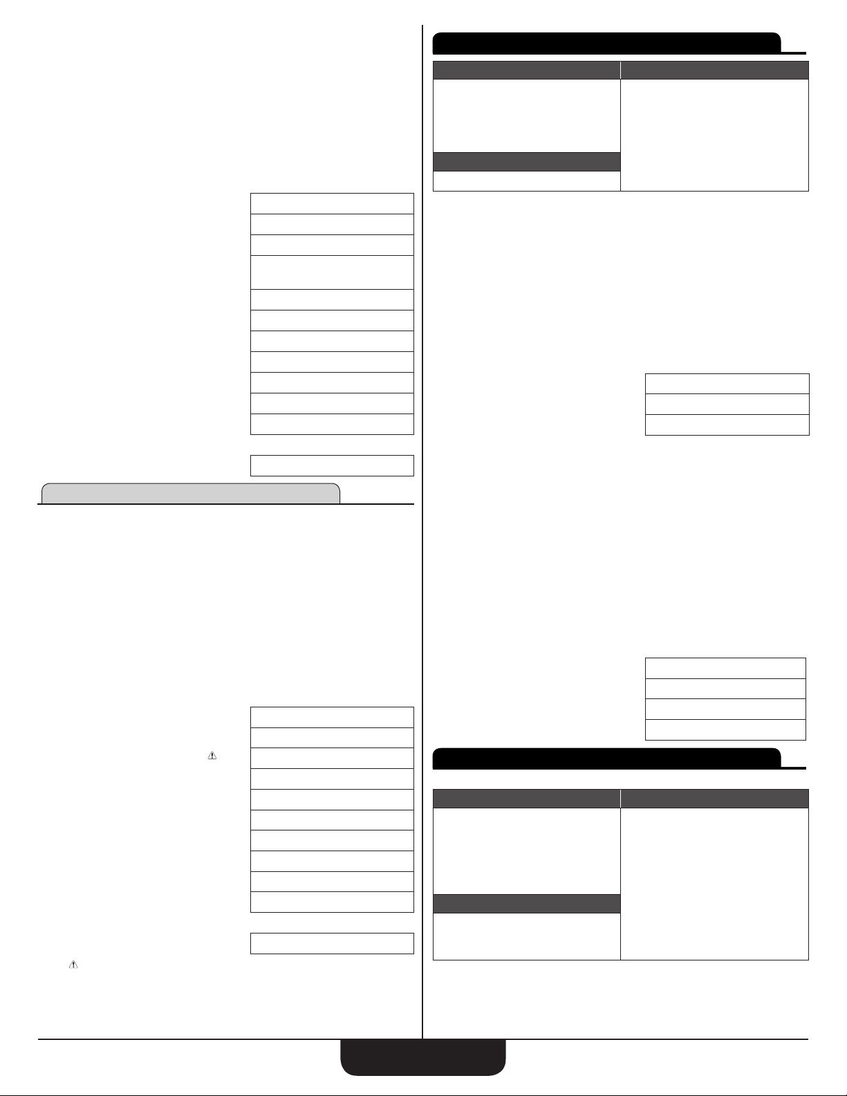
Open Wall
An Open Wall rail set-up has different-length balusters on a tread.
Required Entries Possible Solutions
Inclination Angle
Tread Width
One of these two:
• Number of Balusters per Tread
• Maximum Spacing
Default value: 4"
Optional Entries
Minimum Baluster Width
Short Baluster Height
Number of Treads
Number of Balusters per Tread
Actual Horizontal Baluster Gap*
Baluster On-Center Spacing - Tread
Baluster On-Center Spacing - Rail
Remaining Baluster Heights
Shown if Shortest Baluster Height
is entered.
Baluster On-center Rail Positions
Shown if Number of Treads
is entered
3-11/16 INCH
5-3/16 INCH
4-7/16 INCH
9-5/8 INCH
14-7/8 INCH
20-1/16 INCH
* A caution symbol ( ) is shown if value is greater than stored Maximum
Spacing.
Solve for Open Wall Balusters using an Inclination Angle of 36.5°, 9" Tread
Width, 2 Balusters per Tread, a minimum Baluster Width of 1-1/2" and
Shortest Baluster Height of 24":
1. Clear Calculator:
OOO
2. Start Open Baluster function:
Cb
3. Enter Inclination Angle:
36.5e
4. Enter Tread Width:
9ie
5. Enter 2 Balusters per Tread:
2e
6. Enter 1-1/2" Balusters Minimum Width:
1i1/ 2e
7. Enter Shortest Baluster Height:
24ie
8. Enter 6 Treads and solve for Open Wall Balusters:
6e
ACTUAL HORIZ BAL GAP
BAL OC SPACING TRED
e
BAL OC SPACING RAIL
e
BALUSTER HEIGHT Ø1
e
BAL OC RAIL POS. Ø1
e
BAL OC RAIL POS. Ø2
e
Continued presses of e will display all Rail Positions.
BAL OC RAIL POS. 12
e
MATERIALS FUNCTIONS
Press the N key to access the Materials function. Continued presses of
the
Material you′re working with, press
required dimensions and quantities.
4.
Required Entries Solutions
Wall Length
Courses or Height
Wall Area
Block Height
Block Length
Waste Factor
Using the default values, calculate the number of Blocks and coverage area for
a wall 18′ long and 6′ 6" high:
key will scroll though the available Materials. When you nd the
N
• Blocks (for Block walls)
• Drywall (Sheets)
• Fencing
• Footing (Volume)
• Pavers
• Roofing
• Studs
• Tile (Tile and Grout Quantity)
Blocks
• Required if Wall Length not
entered
• Default value: 8"
• Default value: 16"
• Default value: 5%
, and you will be prompted for the
e
Number of Blocks
Coverage Area
3 INCH
4-1/2 INCH
5-5/8 INCH
27-5/16 INCH
5-5/8 INCH
11-3/16 INCH
67-3/16 INCH
ConstruCtion Master Plus eZ
11
Page 12

1. Clear Calculator:
OOO
2. Start Materials function:
N
3. If necessary, continue pressing N until BLOCKS displays
4. Start Blocks function:
e
5. Enter 18′ Wall Length:
18fe
6. Enter 6′ 6" Wall Height:
6f6ie
7. Accept 8" default value for Block Height:
e
8. Accept 16" default value for Block Length:
e
9 Accept 5% default value for Waste Factor and solve for Blocks:
NUMBER OF BLOCKS 139.
e
COVERAGE AREA
e
Drywall
Required Entries Possible Solutions
Room Length
Room Width
Room Height
Ceiling
• 1. Y (Yes, include)
• 2. N (Don′t include)
Sheet Length
• Default value: 8′
Sheet Width
• Default value: 4′
Optional Entries
Waste Factor
• Default value: 5%
Find the amount of Drywall materials needed for a room 30′ long, 25′ wide
and 9′ high. Include the Drywall for the ceiling and use default values for
sheet length, sheet width and waste factor:
1. Clear Calculator:
Number of Sheets - Total
Number of Sheets – Wall
Number of Sheets – Ceiling
Joint Tape Length
Ready-Mix Compound Weight
Number of Drywall Screws
Number of Drywall Nails
Total Wall Area
Total Ceiling Area
Total Drywall Area
117. SQ FEET
OOO
2. Go to Materials function:
N
3. If necessary, continue pressing N until DRY WALL displays
4. Start Drywall function:
e
5. Enter 30′ Room Length:
30fe
6. Enter 25′ Room Width:
25fe
7. Enter 9′ Room Height:
9fe
8. Include Drywall for Ceiling:
1e
9. Accept 8′ default value for Sheet Length:
e
10. Accept 4′ default value for Sheet Width:
e
11. Accept 5% default value for Waste Factor and solve for Drywall Materials:
NUMBER OF SHEETS TTL
e
NUMBER OF SHEETS WALL
e
58.
33.
NUMBER OF SHEETS CEIL
e
JOINT TAPE LNTH
e
READY-MIX COMP. LBS.
e
DRYWALL SCREW QTY.
e
DRYWALL NAIL QTY.
e
TOTAL WALL AREA
e
TOTAL CEILING AREA
e
TOTAL DRYWALL AREA
e
Fencing
Required Entries Possible Solutions
Fence Length
Number of Horizontal Rails
Maximum Post Spacing
• Default value: 96"
Post Width
• Default value: 3-1/2"
Using the default values, calculate Materials needed for a 75′, 3-rail Fence.
1. Clear Calculator:
Number of:
• Fence Sections
• Posts
• Rails
Uniform Rail Length
Maximum Rail Length Remainder
731 FEET 0 INCH
256.
2284.
3655.
990. SQ FEET
750. SQ FEET
1740. SQ FEET
OOO
2. Go to Materials function:
N
3. If necessary, continue pressing Nuntil FENCING displays
4. Start Fencing function:
e
5. Enter Fence Length:
75fe
6. Enter Number of Rails:
3e
7. Accept 96" default value for Maximum Post Spacing:
e
8. Accept 3-1/2" default value for Post Width and solve for Fencing:
FENCE SECTION QTY.
e
FENCE POST QTY.
e
FENCE RAIL QTY.
e
UNIFORM RAIL LNTH
e
MAX RAIL LENGTH REM
e
Footings
Required Entries Possible Solutions
Footing Length
Footing Area
•
Default value: 264 sq inches
Waste Factor
•
Default value: 5%
Optional Entries
Waste Factor
•
Default value: 5%
Calculate Footing Volume needed for a Footing 60′ long using a 256 sq. inch
(16"x16") Footing Area.
1. Clear Calculator:
Footing Volume
7 FEET 2-1/8 INCH
0 FEET 2-1/2 INCH
OOO
2. Go to Materials function:
N
3. If necessary, continue pressing Nuntil FOOTING displays
4. Enter 60 ′ Footing Length:
60fe
25.
10.
11.
30.
ConstruCtion Master Plus eZ
12
Page 13

5. Enter 256 sq. inch default for Footing Area:
256iie
6. Accept 5% default value for Waste Factor and solve for Footing Volume:
FOOTING VOLUME 4.1481481 CU YD.
e
Pavers
Required Entries Possible Solutions
Coverage Length
Coverage Width
Coverage Area
• Required if Coverage Length
not entered
Paver Length
•
Default value: 8"
Paver Width
• Default value: 4"
Optional Entries
Waste Factor
• Default value: 5%
Using default values, calculate the number of Pavers and coverage area for a
patio 35′ long and 18′ wide.
1. Clear Calculator:
Number of Pavers
Coverage Area
OOO
2. Go to Materials function:
N
3. If necessary, continue pressing N until PAVERS displays
4. Start Pavers function:
e
5. Enter 35′ Coverage Length:
35fe
6. Enter 18′ Coverage Width:
18fe
7. Accept 8" default value for Paver Length:
e
8. Accept 4" default value for Paver Width:
e
9. Accept 5% default value for Waste Factor and solve for Pavers:
NUMBER OF BRICKS
e
COVERAGE AREA
e
Roong
Required Entries Possible Solutions
Building Length
Building Area
Required if Building Length not
entered
Building Width
Nails per Shingle
Default value: 4
Nail Length
Default value: 1-1/4"
Pieces per Bundle
Default value: 21
Bundles per Square
Default value: 3
Optional Entries
Roof Pitch
Waste Factor
Default value: 5%
Using default values, nd the Material quantities for a Roof 60′ long,
36′ wide, with an 8" pitch.
Roof Area
Number of Squares
Number of Bundles
Nails Required
Nail Weight
Number of 4x8 Sheets
630. SQ FEET
2977.
1. Clear Calculator:
OOO
2. Start Materials function:
N
3. If necessary, continue pressing N until ROOFING displays
4. Start Roong function:
e
5. Enter 60′ Building Length:
60fe
6. Enter 36′ Building Width:
36fe
7. Enter 8" Roof Pitch:
8ie
8. Accept 5% default value for Waste Factor:
e
9. Accept 4 default value for Nails per Shingle:
e
10. Accept 1-1/4" default value for Nail Length:
e
11. Accept 21 default value for Pieces per Bundle:
e
12. Accept 3 default value for Bundles per Square and solve for
Roong Materials:
ROOF AREA
e
SQUARE QUANTITY
e
BUNDLE QUANTITY
e
GALVANIZED NAILS REQD.
e
NAIL WEIGHT LBS
e
4X8 SHEATHING QTY.
e
Studs
Required Entries Possible Solutions
Wall Length
Number of Corners
Number of Windows
Number of Doors
On-Center Spacing
• Default value: 16″
Optional Entries
Waste Factor
• Default value: 5%
Find the number of Studs required for a wall 40′ long with two corners, two windows and one door.
1. Clear Calculator:
Number of Studs
2595.9969 SQ FEET
27.333333
82.
7056.
33.6
86.
OOO
2. Go to Materials function:
N
3. If necessary, continue pressing N until STUDS displays
4. Start Studs:
e
5. Enter 40' Total Wall Length:
40fe
6. Enter 2 Corners:
2e
7. Enter 2 Windows:
2e
8. Enter 1 Door:
1e
ConstruCtion Master Plus eZ
13
Page 14

9. Accept 16" default value for Stud On-Center Spacing:
e
10. Accept 5% default value for Waste Factor and solve for Number of Studs:
NUMBER OF STUDS 44.
e
Tile
Required Entries Possible Solutions
Room Length
Room Width
Tile Length
Tile Width*
Optional Entries
Grout Width
• Default value: 1/8"
Tile Thickness
• Default value: 1/4"
Waste Factor
• Default value: 5%
* If no Tile Width is entered, it is assumed that it is the same as Tile Length.
Find the materials required to tile a 16′ x 8′ room with 6" tiles using
default values
1. Clear Calculator:
Coverage Area
Number of Tiles
Sanded Grout Weight
Un-Sanded Grout Weight
Number of Backer Boards
Thin-Set – lbs
OOO
2. Go to Materials function
N
3. If necessary, continue pressing N until TILES displays
4. Start Tiles function:
e
5. Enter 16′ Room Length:
16fe
6. Enter 6′ Room Width:
6fe
7. Enter 6" Tile Length:
6ie
8. Accept 6″ Tile Width:
e
9. Accept 1/8" default value for Grout Width:
e
10. Accept 1/4" default value for Tile Thickness:
e
11. Accept 5% default Waste Factor and solve for Tiles:
e
COVERAGE AREA
TILE QUANTITY
e
GROUT-SANDED LBS.
e
GROUT-NO SAND LBS.
e
BACKER BOARDS QTY
e
THIN SET LBS.
e
EXTRAS
Press C N to access the Extras functions. Continued presses of the
key will scroll through available functions. When you nd the function
N
you want, press
• Preferences
• Elliptical Arch
• Crown Molding
• Compound Angle
• Polygons
• Spacing
to begin prompting sequence.
e
96. SQ FEET
387.
10.
8.
7.
64.
Preference Settings
Press
Preferences displays and press
key will toggle between the different Preferences. The
toggle through the available options for each Preference. Press
exit Preferences. Your calculator will keep your Preference Settings until a
Full Reset alters your settings to the default values. You can change your
Preferences at any time.
DESCRIPTION DEFAULT
Fractional
Resolution
U.S. vs.
Metric Mode
Area Answer
Format
Volume
Answer
Format
Target vs.
Maximum
Stair Riser
Rake Wall
Display Order
Jack Rafter
Display Order
Jack Rafter
Alignment
Run vs. Span
Entry
Linear Meter
Rounding
Decimal
Degree
Rounding
Mathematical
Operation
Fractional
Mode
CN
e
v
v
v
v
v
(repeats options) 0-1/16 INCH
v
Second press of e:
(U.S/Metric Unit preference) U.S. MODE 0. INCH
v
(repeats options) U.S. MODE 0. INCH
v
Third press of e:
(Area answer format preference) AREA UNITS STD 0.
v
v
v
(repeats options) AREA UNITS STD 0.
v
, then N to access the Extras functions. Press N until
C
1/16 INCH 1/8, 1/4, 1/2, 1/64, 1/32
U.S. MODE METRIC MODE
STANDARD SQ FEET, SQ YD, SQ M
STANDARD CU YD, CU FEET, CU M
TARGET RISER HEIGHT MAX RISER HGHT.
DESCENDING ASCENDING
DESCENDING ASCENDING
ON-CENTER MATE
RUN SPAN
FIXED ACTUAL
FIXED ACTUAL
ORDER OF ENTRY ORDER OF OPERATIONS
STANDARD FIXED
(Press N until PREFERENCES displays, then e)
(Fractional Resolution) 0-1/16 INCH
. Continued presses of the e
e
OPTIONS
and ^ keys
v
METRIC MODE 0. MM
AREA UNITS SQ FEET 0.
AREA UNITS SQ YD 0.
AREA UNITS SQ M 0.
to
O
0-1/8 INCH
0-1/4 INCH
0-1/2 INCH
0-1/64 INCH
0-1/32 INCH
ConstruCtion Master Plus eZ
14
Page 15

Fourth press of e:
(Volume answer format preference) VOLUME UNITS STD. 0.
v
v
v
(repeats options) VOLUME UNITS STD. 0.
v
Fifth press of
(Stair Riser Height Preference – Target gets calculation as close
to Target Riser Height as possible. Max calculation will not exceed
Maximum Riser Height.)
e
:
v
(repeats options) TARGET RISER HGHT. 0.
v
Sixth press of
(Rake Preference – Sets Rake-Wall Stud sizes to Descending or
Ascending order.)
e
:
v
(repeats options) DESCENDING RAKE 0
v
Seventh press of
(Jack Preference – Sets Jack Rafters to Descending or Ascending order)
e
:
v
(repeats options) DESCENDING JACK 0.
v
Eighth press of
(Jack Alignment Preference – Sets Jack Spacing to On-center or Mate)
e
:
v
(repeats options) JACK ALIGNMENT OC 0.
v
Ninth press of
(Run/Span Preference – Span is the length of a top plate or twice the length
of the Run)
e
:
v
(repeats options) RUN/SPAN SETTING RUN 0.
v
Tenth press of
(Linear Meters format Preference)
e
:
v
(repeats options) LINEAR METERS FIX M 0.000
v
Eleventh press of
(Degrees format Preference)
e
:
v
(repeats options) DEGREES — FIXED 0.00 °
v
Twelfth press of e:
(Order of Entry Preference)
v
(repeats options) ORDER OF ENTRY MATH 0.
v
VOLUME UNITS CU YD 0.
VOLUME UNITS CU FEET 0.
VOLUME UNITS CU M 0.
TARGET RISER HGHT. 0.
MAX RISER HGHT. 0.
DESCENDING RAKE 0.
ASCENDING RAKE 0.
DESCENDING JACK 0.
ASCENDING JACK 0.
JACK ALIGNMENT OC 0.
JACK ALIGNMENT MATE 0.
RUN/SPAN SETTING RUN 0.
RUN/SPAN SETTING SPAN 0.
LINEAR METERS FIX M 0.000
LINEAR METERS ACT. M 0.
DEGREES — FIXED 0.°
DEGREES — ACTUAL 0.00 °
ORDER OF ENTRY MATH 0.
ORDER OF OPER MATH 0.
Elliptical Arch Function
Required Entries Possible Solutions
Height
Width
Stud On- Center Spacing
•
Default value: 16″
Stud Location
•
Default setting: Outside the Arch*
Optional Entries
Base Height
* Stud Position or Location refers to the placement of the studs:
• Entering 1 calculates studs located Outside of the Arch
• Entering 2 calculates studs located Inside of the Arch.
Note: All Elliptical Arch solutions are based on 180° arch angles.
Solve for an Elliptical Arch that is 5′ high, 15′ wide with studs Outside the Arch:
1. Clear Calculator:
Center to Foci Length
Foci to Foci Length
String Point-to-Point Length
String Loop Length
Arch Area
Center Stud Length
Other Stud Lengths
OOO
2. Go to Extras function:
CN
(If necessary, continue pressing
3. Star t Elliptical Arch function:
until ELLIPTICAL ARCH displays.)
N
e
4. Enter Elliptical Arch Height:
5fe
5. Enter Elliptical Arch Width:
15fe
6. No Base Height:
e
7. Accept 16″ Stud On-Center Spacing default value:
e
8. Accept default Stud Position (Outside the Arch) and solve for Elliptical Arch:
e
CENTER TO FOCI LNTH 5 FEET 7–1/16 INCH
FOCI TO FOCI LNTH 11 FEET 2–3/16 INCH
e
STRING PT. TO PT. LNTH 15 FEET 0 INCH
e
STRING LOOP LNTH 26 FEET 2–3/16 INCH
e
ARCH AREA 235.61945 SQ FEET
e
CENTER STUD LNTH 0 FEET 0 INCH
e
STUD PAIR LENGTH Ø1 0 FEET 0–15/16 INCH
e
STUD PAIR LENGTH Ø2 0 FEET 3–15/16 INCH
e
STUD PAIR LENGTH Ø3 0 FEET 9–1/4 INCH
e
STUD PAIR LENGTH Ø4 1 FEET 5–13/16 INCH
e
STUD PAIR LENGTH Ø5 2 FEET 8–1/2 INCH
e
STUD PAIR LENGTH Ø6 5 FEET 0 INCH
e
Crown Molding Function
Required Entries Possible Solutions
Wall Corner Angle
•
Default value: 90°
Spring Angle
•
Default value: 45°
Solve for Crown Molding with a Corner Angle of 60º and a Spring Angle of 38º:
1. Clear Calculator:
Miter Angle
Bevel Angle
OOO
2. Go to Extras function:
CN
(If necessary, continue pressing N until CROWN MOLDING displays.)
ConstruCtion Master Plus eZ
15
Page 16

3. Star t Crown Molding function:
e
4. Enter Corner Angle of 60º:
60e
5. Enter 38º Spring Angle and solve for Crown Molding:
38e
MITER ANGLE 46.84°
BEVEL ANGLE 43.03°
e
Compound Angle Function
Required Entries Possible Solutions
Number of Sides
Corner Angle
•
Required if Number of Sides
not entered
Tilt Angle
Solve for 8 sides and a tilt angle of 85°:
1. Clear Calculator:
• Miter Cut Angle
• Miter Blade Angle
• Corner Angle
OOO
2. Go to Extras function:
CN
(If necessary, continue pressing N until COMPOUND ANGLE displays.)
3. Star t Compound Angle function:
e
4. Enter number of Sides:
8e
5. Enter Tilt Angle and solve Compound Angle:
85e
MITER ANGLE 2.07°
MITER BLADE ANGL 66.98°
e
CORNER ANGLE 135.00°
e
Solve for a corner angle of 120° and a tilt angle of 45°:
1. Clear Calculator:
OOO
2. Go to Extras function:
CN
(If necessary, continue pressing
3. Star t Compound Angle function:
until COMPOUND ANGLE displays.)
N
e
4. No entry for Sides:
e
5. Enter Corner Angle:
120e
6. Enter Tilt Angle and solve Compound Angle:
45e
MITER ANGLE 22.21°
MITER BLADE ANGL 37.76°
e
Polygon Function
Required Entries Possible Solutions
Number of Sides
One of these required:
•
Side Length
• Outside Diameter
• Inside Diameter
Solve for a Polygon with 8 sides, each 10′ long:
Exterior Angle
Interior Angle
Side Length
Outside Diameter
Inside Diameter
Perimeter
Area
1. Clear Calculator:
OOO
2. Go to Extras function:
CN
(If necessary, continue pressing N until P OLYG O N displays.)
3. Star t Polygon function
e
4. Enter number of Sides:
8e
5. Enter Side Length and solve Polygon:
10fe
OUTSIDE ANGLE 45.00°
INSIDE ANGLE 135.00°
e
OUTSIDE DIAMETER 26 FEET 1–9/16 INCH
e
INSIDE DIAMETER 24 FEET 1–11/16 INCH
e
PERIMETER 80 FEET 0 INCH
e
AREA 482.84271 SQ FEET
e
Solve for a Polygon with 6 sides and an outside diameter of 5′ 6″:
1. Clear Calculator:
OOO
2. Go to Extras function:
CN
(If necessary, continue pressing
3. Star t Polygon function:
until P OLYG O N displays.)
N
e
4. Enter 6 Sides:
6e
5. No Side Length:
e
6. Enter Outside Diameter of 5′ 6″ and solve for Polygons:
5f6ie
OUTSIDE ANGLE 60.00°
INSIDE ANGLE 120.00°
e
SIDE LENGTH 2 FEET 9 INCH
e
INSIDE DIAMETER 4 FEET 9–3/16 INCH
e
PERIMETER 16 FEET 6 INCH
e
AREA 19.647951 SQ FEET
e
Spacing Function
Required Entries Possible Solutions
Coverage Length
At least one of these:
•
Object Quantity
•
Target On-Center Spacing
Optional Entries
Object Width
• Default value: 1-1/2″
Number of End Pieces
End Position*
End Location*
Mark Position
• ID - Inside Dimension
• OC – On-Center
• OD – Outside Dimension
* End Position and End Location are only displayed if only one end piece is entered.
Find the spacing between three 42″ ceiling fans equally spaced across a
25′ ceiling:
See Diagrams on page 22 ►
Number of Objects
Object Spacing
Object Gap
Various Object Positions
ConstruCtion Master Plus eZ
16
Page 17

1. Clear Calculator:
OOO
2. Go to Extras function:
CN
(If necessary, continue pressing
3. Star t Spacing function:
until SPACI NG displays.)
N
e
4. Enter Coverage Length:
25fe
5. Enter 42″ Object Width:
42ie
6. Enter Quantity:
3e
7. No End Pieces:
e
8. Accept default Mark Position (On-Center) and solve for Spacing:
e
OBJECT OC SPCG 7 FEET 1-1/2 INCH
OBJECT GAP 3 FEET 7-1/2 INCH
e
OBJECT POSITION 01 5 FEET 4-1/2 INCH
e
OBJECT POSITION 02 12 FEET 6 INCH
e
OBJECT POSITION 03 19 FEET 7-1/2 INCH
e
Find the spacing between ve 6" wide light xtures fans equally spaced across
a 35’ ceiling:
See Diagrams on page 22 ►
1. Clear Calculator:
OOO
2. Go to Extras function:
CN
(If necessary, continue pressing
3. Star t Spacing function:
until SPACI NG displays.)
N
e
4. Enter Coverage Length:
35fe
5. Enter Object Width:
6ie
6. Enter Object Quantity:
3e
7. No End Pieces:
e
8. Accept default Mark Position (On-Center) and solve for Spacing:
e
OBJECT OC SPCG 5 FEET 11 INCH
OBJECT GAP 5 FEET 5 INCH
e
OBJECT POSITION 01 5 FEET 8 INCH
e
OBJECT POSITION 02 11 FEET 7 INCH
e
OBJECT POSITION 03 17 FEET 6 INCH
e
OBJECT POSITION 04 23 FEET 5 INCH
e
OBJECT POSITION 05 29 FEET 4 INCH
e
Appendix A
PREFERENCE SETTINGS
The Construction Master Plus EZ has Preference Settings that allow you
to customize or set desired unit formats and calculations. Press
to access the Extras functions. Press N until PREFERENCES
N
displays and press
through the different Preferences. The
available options for each Preference. Press
. Continued presses of the e key will scroll
e
and ^ keys scroll through the
v
to exit Preferences.
O
, then
C
ConstruCtion Master Plus eZ
If you replace your batteries or perform a Full Reset* (turn calculator off,
hold down
default settings (in addition to the Default Values listed on pages 3-4), with
the default setting for each preference listed rst.
*Depressing the Reset button located above the o key will also perform a Full Reset.
Preference Options
1) Fractional
Resolution
2) U.S. vs. Metric
Mode
3) Area Answer
Format
4) Volume Answer
Format
5) Target vs.
Maximum Stair
Riser
17
, and press O), your calculator will return to the following
x
– 1/16: displays fractional values to the nearest
16th of an Inch.
– 1/32: displays fractional values to the nearest
32nd of an Inch.
– 1/64: displays fractional values to the nearest
64th of an Inch.
– 1/2: displays fractional values to the nearest half
Inch.
– 1/4: displays fractional values to the nearest
quarter Inch.
– 1/8: displays fractional values to the nearest 8th
of an Inch.
– U.S. Mode: unitless values stored within
Construction functions are automatically
assigned the corresponding default U.S. units of
the selected function.
– Metric Mode: unitless values stored within
Construction functions are automatically
assigned the corresponding default Metric units
of the selected function.
– STANDARD: if units entered are the same – e.g.,
Inch x Inch – area answers will remain in this
format (Square Inch), but if units entered are
different – e.g., Inches x Feet – area answers will
be displayed in Square Feet.
– SQUARE FEET: area answers always displayed
in Square Feet, regardless of unit entry – e.g.,
Inches x Inches = Square Feet.
– SQUARE YARDS: area answers always
displayed in Square Yards, regardless of unit
entry – e.g., Feet x Feet = Square Yards.
– SQUARE METERS: area answers always
displayed in Square Meters, regardless of unit
entry – e.g., Feet x Feet = Square Meters.
– STANDARD: if units entered are the same – e.g.,
Feet x Feet x Feet – area answers will remain in
this format (Cubic Feet), but if units entered are
different – e.g., Feet x Feet x Inches – volume
answer will be displayed in Cubic Yards.
– CUBIC YARDS: volume answers always
displayed in Cubic Yards, regardless of unit entry
– e.g., Feet x Feet x Inches – volume answer will
be displayed in Cubic Yards.
– CUBIC FEET: volume answers always displayed
in Cubic Feet, regardless of unit entry – e.g.,
Inches x Inches x Inches = Cubic Feet.
– CUBIC METERS: volume answers always
displayed in Cubic Meters, regardless of unit
entry – e.g., Feet x Feet x Feet = Cubic Meters.
– TARGET RISER HEIGHT: The calculated Actual
Riser Height will be as close to the Target Riser
Height as possible. The calculated Actual Riser
Height will be either shorter or taller than the
Target Riser Height.
– MAXIMUM RISER HEIGHT: The calculated
Actual Riser Height will not exceed the Maximum
Riser Height.
Page 18

6) Rake Wall
Display Order
7) Jack Rafter
Display Order
8) Jack Rafter
Alignment
9) Run vs. Span
Entry
10) Linear Meter
Rounding
11) Decimal Degree
Rounding
12) Mathematical
Operation
13) Fractional Mode – Standard: Fractions are displayed to the nearest
– DESCENDING RAKE: Rake Wall studs are
displayed from largest to smallest size.
– ASCENDING RAKE: Rake Wall studs are
displayed from smallest to largest size.
– DESCENDING: Jack Rafters are displayed from
largest to smallest size.
– ASCENDING: Jack Rafters are displayed from
smallest to largest size.
– JACK ALIGNMENT OC: On-center spacing
maintained on both regular and irregular sides.
– JACK ALIGNMENT MATE: On-center spacing
not maintained on both sides (regular/irregular
Jack Rafters “mate” at the Hip/Valley).
– Run: Value for Run (half the distance of Span) is
used for rafter calculations).
– Span: Value for Span (twice the distance of Run)
is used for rafter calculations).
– 0.000 (FIX): Metric calculation results are always
displayed to three decimal places.
– 0. (ACTUAL): Metric calculation results are
always displayed to the maximum number of
decimal places.
– 0.00º (FIXED): Decimal degree results are
always displayed to two decimal places.
– 0.º (ACTUAL):
– Order of Operations: The calculator uses the
Order of Operations Method (10 + 4 x 5 = 30).
– Order of Entry: The calculator uses the Order of
Entry Method (as entered: 10 + 4 x 5 =70).
Fractional Resolution.
– Fixed: Fractions are displayed in the set
Fractional Resolution.
Appendix B
BASIC CALCULATOR FUNCTIONS AND
DIMENSIONAL MATH OPERATIONS
Linear Dimensions
Examples of how linear dimensions are entered
(press
Dimensions Keystroke
4.5 Inches
95 millimeters
85 centimeters
1,320 Feet
201 meters
Square and Cubic Dimensions
Examples of how square and cubic dimensions are entered
(press
14 square Inches
5 square meters
1.5 cubic meters
3 cubic Feet
after each entry):
O
after each entry):
O
4.5i
95C9
85C7
1320f
201m
14ii
5mm
1.5mmm
3fff
CONVERSIONS
Linear Conversions
Convert 10 Feet 6 Inches to other dimensions, including metric:
OO
10f6i
Ci
Cf
10 FEET 6 INCH
126 INCH
10 FEET 6 INCH
Cy
Cm
(centimeters) 320.04 CM
C7
(millimeters) 3200.4 MM
C9
Convert 15 Feet 9-1/2 Inches to decimal Feet. Then convert back to
Feet-Inch-Fractions.
3.200 M
OO
15f9i1/2
Cf
Cf
Convert 8-1/8 Inches to decimal Inches. Then convert to decimal Feet.
15 FEET 9-1/2 INCH
15.791667 FEET
15 FEET 9-1/2 INCH
OO
8i1/8
Ci
Cf
Convert 9.0625 Inches to fractional Inches. Then convert to decimal Feet.
8-1/8 INCH
8.125 INCH
0.6770833 FEET
OO
9.0625i
Ci
Cf
Square and Cubic Conversions
Convert 6 square Feet to other square dimensions:
9.0625 INCH
9-1/16 INCH
0.7552083 FEET
OO
6ff
(millimeters) 557418.24 SQ MM
C9
Cm
(centimeters) 5574.1824 SQ CM
C7
Convert 0.05 cubic meters to other dimensions:
6 SQ FEET
0.5574182 SQ M
OO
.05mmm
(millimeters) 50000000. CU MM
C9
(centimeters) 50000. CU CM
C7
Ci
Cf
Weight Conversions
Convert 1.5 tons to pounds and kilograms:
3051.1872 CU INCH
1.7657333 CU FEET
0.05 CU M
OO
1.5C6
C1
C4
(Tons) 1.5 TON
(kilograms) 1360.7741 KG
(lbs) 3000. LBS
0.
3.5 YD
0.
0.
0.
0.
0.
0.
ConstruCtion Master Plus eZ
18
Page 19
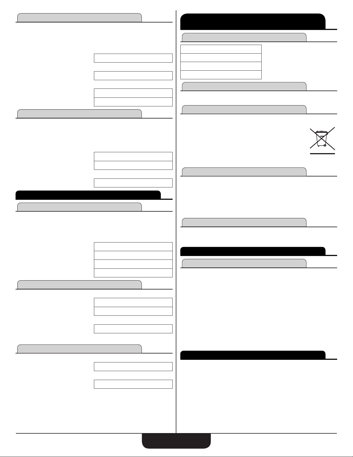
Weight per Volume Conversions
Find the weight of 15 cubic yards of gravel. The gravel weighs 1.75 tons
per cubic Yard.
Note: The default weight conversion is 1.5 tons per cubic yard.
1. Enter the weight per cubic yard:
1.75C5
2. Enter the volume of gravel and nd the weight:
15yyyC6
3. Find the weight in metric tons and pounds:
C3
C4
Calculating Percentages
key can be used for nding a given percent of a number or for
The
%
working add-on, discount or division percentage calculations. It can be
used with any type of number, in any dimension (Feet, Inch, millimeter, etc.)
and any type of convention (non-dimensioned, linear, square or cubic).
Find 18% of 50 Feet:
1.75 TONS/CU. YARD
26.25 TON
23.813599 MTON
52500 LBS.
OO
50fx18%
Take 20% from 17 Feet 6 Inches:
17f6i-20%
BASIC MATH OPERATIONS
Adding and Subtracting Dimensions
Add the following measurements:
• 6 Feet 2-1/2 Inches
• 11 Feet 5-1/4 Inches
• 18.25 Inches
Then subtract 2-1/8 Inches.
6f2i1/2+
11f5i1/4+
18.25i=
-2i1/8=
Multiplying Dimensions
Multiply 5 Feet 3 Inches by 11 Feet 6-1/2 Inches:
5f3ix
11f6i1/2=
Multiply 2 Feet 7 Inches by 10:
2f7ix10=
9 FEET 0 INCH
14 FEET 0 INCH
6 FEET 2-1/2 INCH
17 FEET 7-3/4 INCH
19 FEET 2 INCH
18 FEET 11-7/8 INCH
5 FEET 3 INCH
60.59375 SQ FEET
25 FEET 10 INCH
Dividing Dimensions
Divide 30 Feet 4 Inches by 7 Inches:
30f4i÷7i=
Divide 20 Feet 3 Inches by 9:
20f3i÷9=
2 FEET 3 INCH
52.
APPENDIX C – ACCURACY/ERRORS, AUTO
SHUT-OFF, BATTERIES, RESET
Error Codes
OVERFLOW
MATH ERROR
DIMENSION ERROR
ENTRY ERROR
Auto Shut-Off
Your calculator is designed to shut of f after about 4 minutes of non-use.
Battery
The Construction Master Plus EZ uses one CR2025
(included). This should last approximately 800 hours of
actual use. Should your calculator display become very
dim or erratic, replace the battery.
Note: Please use caution when disposing of your old battery, as it
contains hazardous chemicals. Replacement batteries are available
at most discount or electronics stores. You may also call Calculated
0.
Industr ies at 1-775- 885 -49 00.
Battery Replacement Instructions
While the calculator is off, turn the calculator over and use a
#1 Phillips screwdriver to remove the battery holder screw located near
the center at the top. With the screw removed, pull battery holder out,
remove old battery, and slide new battery into holder. The negative side of
the battery should be facing you as you insert the battery holder into the
calculator. Replace screw using a #1 Phillips screwdriver.
Reset
If your calculator should ever "lock up," insert the tip of a paperclip or a
small diameter wire into the small Reset hole above the
Overow (too large)
Divide by 0
Dimension error
Invalid entry error
o
REPAIR AND RETURN
Return Guidelines
1. Please read the Warranty in this User's Guide to determine if your Calculated Industries product remains under warranty before calling or return-
ing any device for evaluation or repairs.
2. If your product won't turn on, check the battery as outlined in the User's
Guide.
3. If you need more assistance, please go to the website listed below.
4. If you believe you need to return your product, please call a Calculated
Industries representative from 7 a.m. to 4 p.m. Pacic Time for additional
information and a Return Authorization (RA).
Call Toll Free: 1-800-854-8075
Outside USA: 775-885-4900
www.calculated.com/warranty
wARRANTY
Calculated Industries ("CI") warrants this product against defects in
materials and workmanship for a period of one (1) year from the date
of original consumer purchase in the U.S. If a defect exists during
the warranty period, CI at its option will either repair (using new or
remanufactured parts) or replace (with a new or remanufactured calculator)
the product at no charge.
key.
ConstruCtion Master Plus eZ
19
Page 20

THE WARRANTY WILL NOT APPLY TO THE PRODUCT IF IT HAS
BEEN DAMAGED BY MISUSE, ALTERATION, ACCIDENT, IMPROPER
HANDLING OR OPERATION, OR IF UNAUTHORIZED REPAIRS ARE
ATTEMPTED OR MADE. SOME EXAMPLES OF DAMAGES NOT
COVERED BY WARRANTY INCLUDE, BUT ARE NOT LIMITED TO,
BATTERY LEAKAGE, BENDING, A BLACK "INK SPOT" OR VISIBLE
CRACKING OF THE LCD, WHICH ARE PRESUMED TO BE DAMAGES
RESULTING FROM MISUSE OR ABUSE.
To obtain warranty service in the U.S., please go to the website. A repaired
or replacement product assumes the remaining warranty of the original
product or 90 days, whichever is longer.
Non-Warranty Repair Service – U.S.A.
Non-warranty repair covers service beyond the warranty period, or service
requested due to damage resulting from misuse or abuse. Contact
Calculated Industries at the number listed above to obtain current product
repair information and charges. Repairs are guaranteed for 90 days.
Repair Service – Outside the U.S.A.
To obtain warranty or non-warranty repair service for goods purchased
outside the U.S., contact the dealer through which you initially purchased
the product. If you cannot reasonably have the product repaired in your
area, you may contact CI to obtain current product repair information and
charges, including freight and duties.
Disclaimer
CI MAKES NO WARRANTY OR REPRESENTATION, EITHER
EXPRESS OR IMPLIED, WITH RESPECT TO THE PRODUCT'S
QUALITY, PERFORMANCE, MERCHANTABILITY, OR FITNESS FOR A
PARTICULAR PURPOSE. AS A RESULT, THIS PRODUCT, INCLUDING
BUT NOT LIMITED TO, KEYSTROKE PROCEDURES, MATHEMATICAL
ACCURACY AND PREPROGRAMMED MATERIAL, IS SOLD "AS IS,"
AND YOU THE PURCHASER ASSUME THE ENTIRE RISK AS TO ITS
QUALITY AND PERFORMANCE. IN NO EVENT WILL CI BE LIABLE FOR
DIRECT, INDIRECT, SPECIAL, INCIDENTAL, OR CONSEQUENTIAL
DAMAGES RESULTING FROM ANY DEFECT IN THE PRODUCT OR ITS
DOCUMENTATION.
LOOKING FOR NEW IDEAS
Calculated Industries, a leading manufacturer of special-function
calculators and measuring instruments, is always looking for new product
ideas in these areas.
If you have a new product idea, please visit our "Bright Idea" page at
www.calculated.com/brightidea.asp. For suggestions about improving this
product or other products, please visit us at www.calculated.com under
"Contact Us". Thank You.
4840 Hytech Drive
Carson City, NV 89706 U.S.A.
1-800-854-8075 • Fax: 1-775-885-4949
E-mail: info@calculated.com
www.calculated.com
Designed in the United States of America.
11/14
UG4067E-A
The warranty, disclaimer, and remedies set forth above are exclusive and
replace all others, oral or written, expressed or implied. No CI dealer, agent,
or employee is authorized to make any modication, extension, or addition
to this warranty.
Some states do not allow the exclusion or limitation of implied warranties or
liability for incidental or consequential damages, so the above limitation or
exclusion may not apply to you. This warranty gives you specic rights, and
you may also have other rights, which vary from state to state.
FCC Class B
This equipment has been certied to comply with the limits for a Class B
calculating device, pursuant to Subpart J of Part 15 of FCC rules.
Legal Notes
Software copyrighted and licensed by Calculated Industries, Inc., 2014.
User's Guide copyrighted by Calculated Industries, Inc., 2014. Construction
Master® and Calculated Industries® are registered trademarks of
Calculated Industries, Inc. 2014.
ALL RIGHTS RESERVED
Designed in the U.S.A.
ConstruCtion Master Plus eZ
20
Page 21

arch studs
4' 10-1/2"
4
4' 9-1/8"
3
2' 11/16"
2
2' 9/16"
1
2' 9/16"
Center Stud
2' 9/16"
1
2' 11/16"
2
4' 9-1/8"
3
◄ Back
4' 10-1/2"
4
2' Base
2' 10-1/2"
4
2' 9-1/8"
3
11-3/16"
2
2-9/16"
1
8' 1" Chord Length
2' 9/16"
Center Stud
2-9/16"
1
11-3/16"
2
2' 9-1/8"
3
2' 10-1/2"
Arch
Height
2' 10-1/2"
4
2' 10"
Arch
Height
8' 1" Chord Length
ConstruCtion Master Plus eZ
21
Page 22

Rake Wall function
4' Rise
3' 10-11/16"
Differential Length
10-11/16"
Top Plate Length
2' 11-1/2"
7' 2-2/16"
2' 7/8"
Top Plate
Thickness
1-1/2"
1' 2-3/16"
◄ Back
12"
8"
3' 1/2"
Ø1 Ø2 Ø3 Ø4 Ø5
Spacing function
Fans Example
Objects
42' wide
Position 1
5' 4-1/2"
Lights Example
On-Center spacing
7' 1-1/2"
Position 2
12' 6"
Inclination Angle
33.69°
6' Run
◄ Back
Object Gap
3' 7-1/2"
Position 2
19' 7-1/2"
◄ Back
35'
Object Spacing
Position Ø1
5' 8"
from wall
5' 11"
Position Ø2
11' 7"
from wall
Object
Gap 5'
Position Ø3
17' 6"
from wall
ConstruCtion Master Plus eZ
22
Position Ø4
23' 5"
from wall
Position Ø5
29' 4"
from wall
Page 23
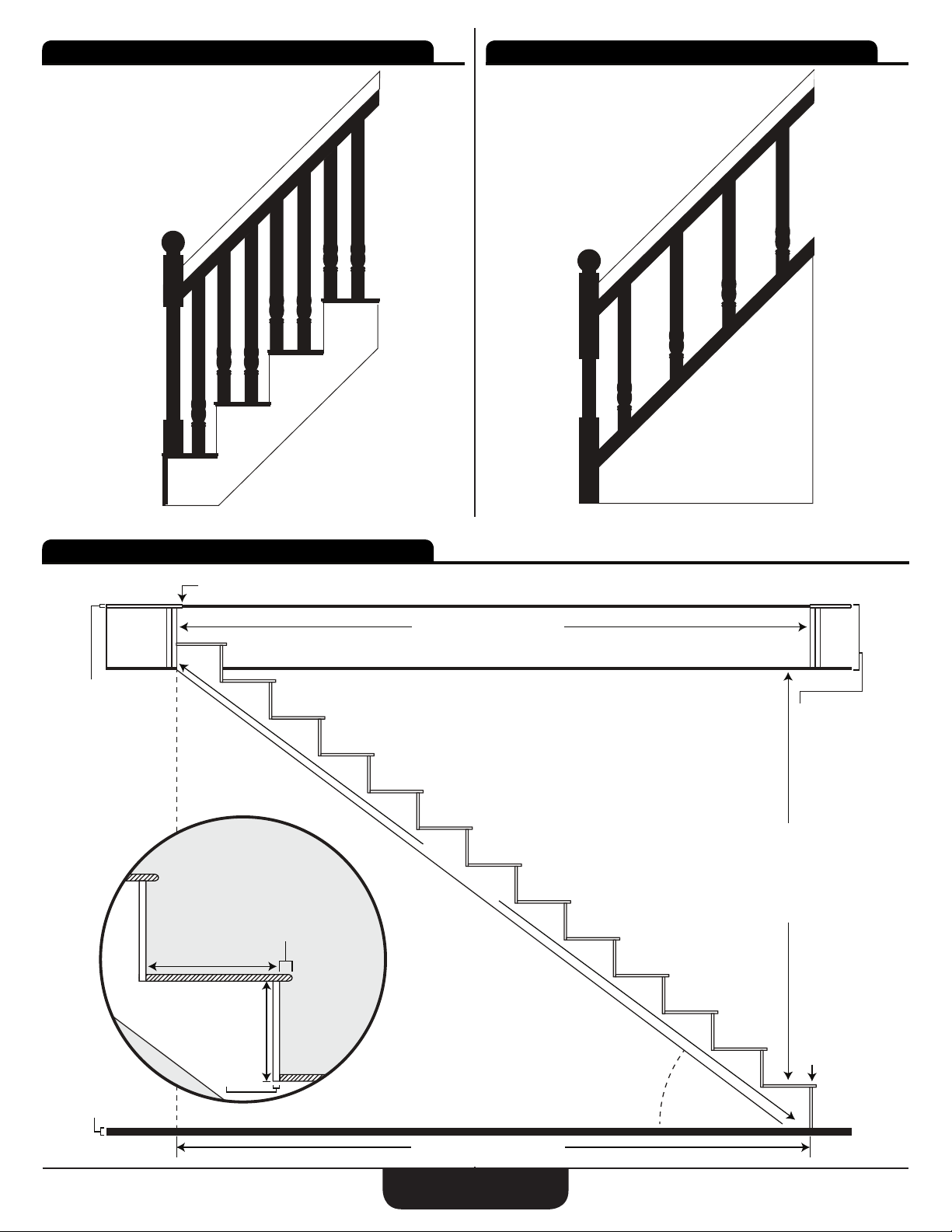
Open Wall balusters
Cap Wall balusters
◄ Back ◄ Back
stairs
Upper
Flooring
Thickness
Toe Position Last
Tread Width
◄ Back
Minimum Stairwell Opening
Top
Floor
Thickness
Headroom Height
Stringer Length
Nosing Length
Lower
Flooring
Thickness
Riser
Height
Riser
Thickness
Toe
Position 1
Inclination
Angle
Minimum Stairwell Opening
ConstruCtion Master Plus eZ
23
 Loading...