


CVW93612MSS

Owner’s Manual & Installation Instructions
Vented Range Hoods
Models: CVW9301 and CVW9361
Contents
Safety Information ...............................3
Using the Hood
Controls ......................................5
Care And Cleaning
Filter .........................................6
Surfaces ......................................6
Lights ........................................7
Installation Instructions ..........................8
Troubleshooting Tips ...........................20
Limited Warranty ...............................22
Accessories ...................................23
Consumer Support .............................24
Write the model and serial numbers here:
Model # _______________________________
Serial # _______________________________
You can find them on a label on the inside of the hood.
Español
Para consultar una version en español de este manual de instrucciones,
visite nuestro sitio de internet cafeappliances.com.
49-2000061 Rev. 1 07-18 GEA

THANK YOU FOR MAKING CAFÉ A PART OF YOUR HOME.
We take pride in the craftsmanship, innovation and design that goes into every CAFÉ product, and
we think you will too. Among other things, registration of your appliance ensures that we can deliver
important product information and warranty details when you need them.
Register your CAFÉ appliance now online. Helpful websites are available in the Consumer Support
section of this Owner’s Manual. You may also mail in the pre-printed registration card included in the
packing material.
2 49-2000061 Rev. 1
IMPORTANT SAFETY INFORMATION
READ ALL INSTRUCTIONS BEFORE USING
SAFETY INFORMATION
WARNING
ELECTRIC SHOCK OR INJURY TO PERSONS,
OBSERVE THE FOLLOWING:
A. Use this unit only in the manner intended by the
manufacturer. If you have questions, contact the
manufacturer.
B. Before servicing or cleaning unit, switch power off
at service panel and lock the service disconnecting
means to prevent power from being switched
on accidentally. When the service disconnecting
means cannot be locked, securely fasten a
prominent warning device, such as a tag, to the
service panel.
C. Do not use this unit with any solid-state speed
control device.
D. This unit must be grounded.
CAUTION
ONLY. DO NOT USE TO EXHAUST HAZARDOUS
OR EXPLOSIVE MATERIALS AND VAPORS.
CAUTION
exhaust air, be sure to duct air outside. Do not vent
exhaust air into spaces within walls or ceilings or into
attics, crawl spaces, or garages.
TO REDUCE THE RISK OF FIRE,
FOR GENERAL VENTILATING USE
To reduce risk of fire and to properly
WARNING
TO PERSONS IN THE EVENT OF A RANGE TOP
GREASE FIRE, OBSERVE THE FOLLOWING*:
A. SMOTHER FLAMES with a close-fitting lid, cookie
sheet or metal tray, then turn off the burner. BE
CAREFUL TO PREVENT BURNS. If the flames do
not go out immediately, EVACUATE AND CALL
THE FIRE DEPARTMENT.
B. NEVER PICK UP A FLAMING PAN—You may be
burned.
C. DO NOT USE WATER, including wet dishcloths or
towels—a violent steam explosion will result.
D. Use an extinguisher ONLY if:
1. You know you have a Class ABC extinguisher,
and you already know how to operate it.
2. The fire is small and contained in the area where
it started.
3. The fire department is being called.
4. You can fight the fire with your back to an exit.
* Based on “Kitchen Fire Safety Tips” published by NFPA.
WARNING
RANGE TOP GREASE FIRE:
A. Never leave surface units unattended at high
settings. Boil overs cause smoking and greasy
spillovers that may ignite. Heat oils slowly on low or
medium settings.
TO REDUCE THE RISK OF INJURY
TO REDUCE THE RISK OF A
B. Always turn hood ON when cooking on high heat or
when flambéing food (i.e. Crepes Suzette, Cherries
Jubilee, Peppercorn Beef Flambé).
C. Clean ventilating fans frequently. Grease should not
be allowed to accumulate on fan or filter.
D. Use proper pan size. Always use cookware
appropriate for the size of the surface element.
READ AND SAVE THESE INSTRUCTIONS
49-2000061 Rev. 1 3
IMPORTANT SAFETY INFORMATION
READ ALL INSTRUCTIONS BEFORE USING
WARNING
ELECTRIC SHOCK OR INJURY TO PERSONS,
OBSERVE THE FOLLOWING:
A. Installation work and electrical wiring must be
done by qualified person(s) in accordance with
all applicable codes and standards, including
fire-rated construction.
B. Sufficient air is needed for proper combustion and
exhausting of gases through the flue (chimney) of
fuel burning equipment to prevent back drafting.
Follow the heating equipment manufacturer’s
SAFETY INFORMATION
guidelines and safety standards such as those
published by the National Fire Protection
Association (NFPA), the American Society for
Heating, Refrigeration and Air Conditioning
Engineers (ASHRAE) and the local code authorities.
When applicable, install any makeup (replacement)
air system in accordance with local building code
requirements. Visit cafeappliances.com for
available makeup air solutions.
C. When cutting or drilling into wall or ceiling, do not
damage electrical wiring and other hidden utilities.
TO REDUCE THE RISK OF FIRE,
WARNING
USE ONLY METAL DUCTWORK.
Do not attempt to repair or replace any part of your
hood unless it is specifically recommended in this
manual. All other servicing should be referred to a
qualified technician.
TO REDUCE THE RISK OF FIRE,
D. Ducted fans must always be vented to the outdoors.
E. Turn off breaker to adjacent rooms while working.
How to Remove Protective Shipping Film and Packaging Tape
Carefully grasp a corner of the protective shipping film
with your fingers and slowly peel it from the appliance
surface. Do not use any sharp items to remove the film.
Remove all of the film before using the appliance for the
first time.
To assure no damage is done to the finish of the
product, the safest way to remove the adhesive from
packaging tape on new appliances is an application of
a household liquid dishwashing detergent. Apply with a
soft cloth and allow to soak.
NOTE: The adhesive must be removed from all parts.
READ AND SAVE THESE INSTRUCTIONS
4 49-2000061 Rev. 1
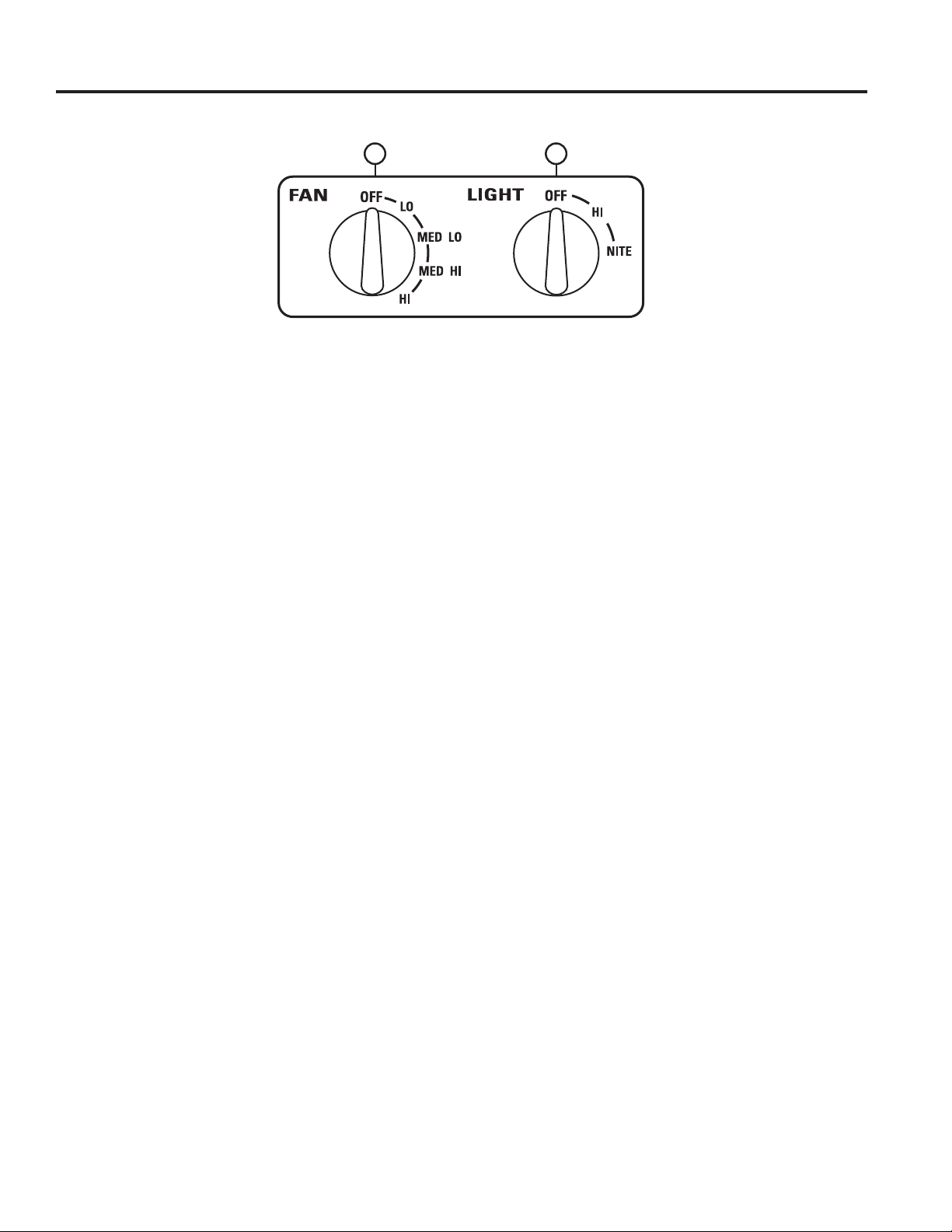
Controls
Throughout this manual, features and appearance may vary from your model.
12
USING THE HOOD: Controls
1. FAN Control: Turn the FAN speed control to LO,
MED LO, MED HI or HI, as needed. Continuous
use of the fan system while cooking helps keep the
kitchen comfortable and less humid. It also reduces
cooking odors and soiling moisture that create a
frequent need for cleaning. NOTE: When the fan
is operating on the LO setting, it will be very quiet.
Always make sure that the fan is turned OFF when
you are finished in the kitchen.
2. LIGHT Control: Turn the LIGHT control to HI for
bright light while cooking. Turn to NITE for use as a
night light.
49-2000061 Rev. 1 5
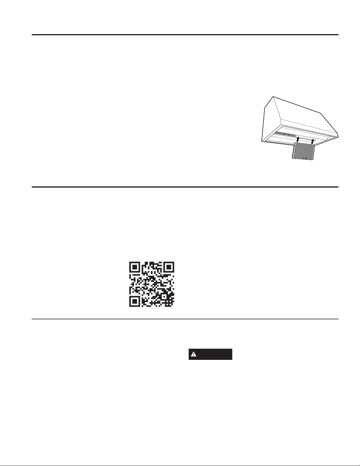
Filter
Be sure the circuit breaker is off and all surfaces are cool before cleaning or servicing any part of the vent hood.
Reusable Metal Grease Filters
The hood has 2 metal reusable grease filters.
The metal filters trap grease released by foods on the
cooktop. They also help prevent flaming foods on the
cooktop from damaging the inside of the hood.
For this reason, the filters must ALWAYS be in place
when the hood is used. The grease filters should be
cleaned once a month, or as needed.
To clean the grease filters, soak them and then swish
them around in hot water and detergent. Don’t use
ammonia or ammonia products because they will darken
the metal. Do not use abrasives or oven cleaners. Light
brushing can be used to remove embedded dirt. Rinse,
shake and let them dry before replacing.
To remove:
Grasp the filter handle and pull it up, forward and out.
To replace:
1. Hold the filter at the
bottom with the handle.
2. Place the top end of the
filter against the inside
front of the hood.
3. Slide it up until it stops
and push the bottom
end back until it snaps
into place.
Surfaces
Stainless Steel Surfaces (on some models)
Do not use a steel wool pad; it will scratch the
surface.
To clean the stainless steel surface, use warm sudsy
water or a stainless steel cleaner or polish. Always wipe
CARE AND CLEANING: Filter / Surfaces
the surface in the direction of the brush line. Follow
the cleaner instructions for cleaning the stainless steel
surface. Cleaners with oxalic acid such as Bar Keepers
Friend Soft Cleanser™ will
remove surface rust, tarnish, and
small blemishes. To receive a
$2.00 coupon for a trial sample
of Bar Keepers Friend Soft
Cleanser™ follow the link below
or scan the QR Code.
www.barkeepersfriend.com/ge
Use only a liquid cleanser free of grit and rub in the
direction of the brush lines with a damp soft sponge.
To inquire about purchasing stainless steel appliance
cleaner or polish, or to find the location of a dealer
nearest you, visit cafeappliances.com/parts.
Painted Surfaces (on some models)
Do not use a steel wool pads or other abrasive
cleaners; they will scratch the surface.
Clean grease-laden surfaces of the hood frequently. To
clean the hood surface, use a hot, damp cloth with a
mild detergent suitable for painted surfaces. About one
tablespoon of ammonia may be added to the water. Use
a clean, hot, damp cloth to remove soap. Dry with a dry,
clean cloth.
6 49-2000061 Rev. 1
NOTE: When cleaning, take care not to come in contact
with filters and other surfaces.
CAUTION
be certain that you do not touch the light with moist
hands or cloth. A warm or hot light may break if
touched with a moist surface. Always let the light
cool completely before cleaning around it.
When cleaning the hood surfaces,
Lights
Be sure electrical power is off and all surfaces are cool before cleaning or servicing any part of the vent hood.
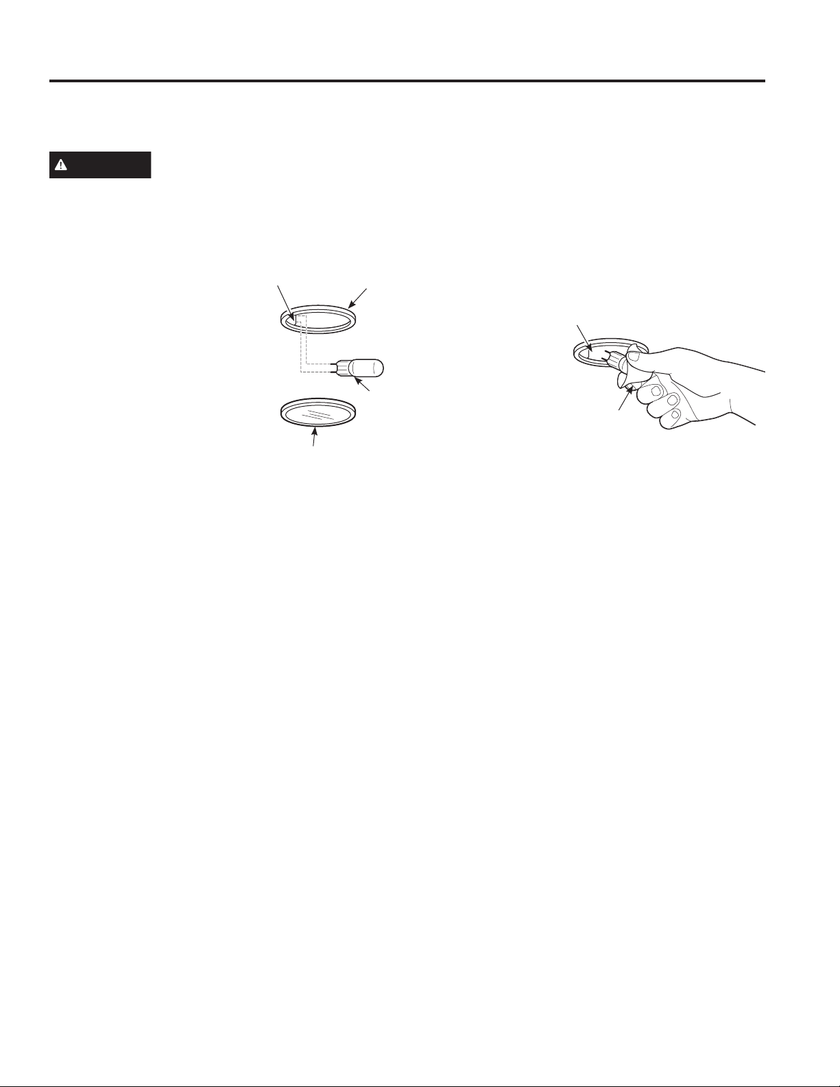
NOTE: The glass cover should be removed only when
cold. Wearing latex gloves may offer a better grip.
CAUTION
disconnect the electrical power to the hood at the main
fuse or circuit breaker panel.
Be sure to let the light cover and bulb cool completely.
For your safety, do not touch a hot bulb with bare hands
or a damp cloth.
To remove:
1. Turn the glass cover
counterclockwise until
the glass cover clears the
socket.
2. Using gloves or a dry cloth,
remove the bulb by pulling it
straight out.
Before replacing your light bulb,
Receptacle
Glass cover
Socket
Bulb
To replace:
1. Use a new 12-volt, 20-watt (maximum)
Halogen bulb for a G-4 base.
2. Using gloves or a dry cloth, remove the new bulb from
its packaging. NOTE: Do not touch the new halogen
bulb with bare fingers. Touching the bulb with bare
fingers will significantly reduce the life of the bulb.
3. Push the bulb straight into the receptacle all the way.
4. Place the glass cover onto the socket and turn
clockwise until secure. For improved lighting, clean
the glass cover
frequently using a
damp cloth. This
should be done
when the hood is
completely cool.
5. Reconnect electrical
power to the hood.
Receptacle
Use
gloves
or cloth
CARE AND CLEANING: Lights
49-2000061 Rev. 1 7
Installation
Range Hoods
Instructions
If you have questions, visit our website at: cafeappliances.com
BEFORE YOU BEGIN
Read these instructions completely and
carefully.
•
IMPORTANT — Save these
instructions for local inspector’s use.
•
IMPORTANT — Observe all governing
codes and ordinances.
• Note to Installer – Be sure to leave these
instructions with the Consumer.
• Note to Consumer – Keep these instructions for
INSTALLATION INSTRUCTIONS
future reference.
• Skill level – Installation of this vent hood requires
basic mechanical and electrical skills.
• Completion time – Approximately 1 to 3 hours
• Proper installation is the responsibility of the
installer.
• Product failure due to improper installation is not
covered under the Warranty.
CAUTION
these vent hoods and to reduce the risk of personal
injury or damage to the product, TWO PEOPLE
ARE REQUIRED FOR PROPER INSTALLATION.
Due to the weight and size of
WARNING
ELECTRIC SHOCK OR INJURY TO PERSONS,
OBSERVE THE FOLLOWING:
A. Installation work and electrical wiring must be
done by qualified person(s) in accordance with
all applicable codes and standards, including
fire-rated construction.
B. Sufficient air is needed for proper combustion
and exhausting of gases through the flue
(chimney) of fuel burning equipment to prevent
back drafting. Follow the heating equipment
manufacturer’s guidelines and safety standards
such as those published by the National Fire
Protection Association (NFPA), the American
Society for Heating, Refrigeration and Air
Conditioning Engineers (ASHRAE) and the local
code authorities.
C. When cutting or drilling into wall or ceiling, do
not damage electrical wiring and other hidden
utilities.
D. Ducted fans must always be vented to the
outdoors.
E. Turn off breaker to adjacent rooms while
working.
WARNING
USE ONLY METAL DUCT WORK.
TO REDUCE THE RISK OF FIRE,
TO REDUCE THE RISK OF FIRE,
FOR YOUR SAFETY
WARNING
switch power off at service panel and lock the
service disconnecting means to prevent power from
being switched on accidentally. When the service
disconnecting means cannot be locked, securely
fasten a prominent warning device, such as a tag,
to the service panel.
Before beginning the installation,
WARNING
at the main circuit breaker or fuse box before
installing.
Disconnect all electrical power
8 49-2000061 Rev. 1
Installation Preparation
INSTALLATION PREPARATION
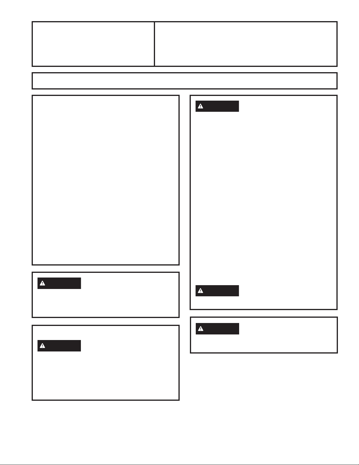
PRODUCT DIMENSIONS
12”
18”
21”
30” Models
Requires a 30” opening.
12”
18”
29-7/8”
INSTALLATION CLEARANCES
These vent hoods are designed to be installed onto
a wall. They may be installed beneath a soffit or
cabinet.
• The hoods are designed to fit 12” deep cabinets.
When installed onto 15” deep cabinets, a filler
panel accessory is available: Order JXS50SS for
30” wide hoods or JXS56SS for 36” wide hoods.
• Install these hoods 24” required minimum and 36”
recommended maximum above the cooking space.
SOFFIT INSTALLATION
SOFFIT
24” Required Minimum and
36” Recommended Maximum
21”
36” Models
Requires a 36” opening.
35-7/8”
In this installation, the ductwork running from the top
of the hood will be concealed in the soffit or upper
cabinetry.
WALL MOUNT INSTALLATION
24” Required Minimum and
36” Recommended Maximum
For this installation, a decorative duct cover is
available to conceal the ductwork running from
the top of the hood. Use of the duct cover requires
special consideration to the installation height above
the countertop. See page 12 for details.
49-2000061 Rev. 1 9
Installation Preparation
OPTIONAL ACCESSORIES
Duct Cover
A decorative duct cover is available to
accommodate 8 to 10 ft. ceiling heights. The duct
cover will expand from 12” minimum or 24” to 36”
maximum height.
• The duct cover conceals the ductwork running
from the top of the hood to the ceiling.
• The duct cover accessory fits both 30” and 36”
wide models. Order the duct cover accessory at
the same time as the vent hood. All accessories
should be on site at the time of hood installation.
Order:
UXCHSS for Stainless Models
UXCHDS for Dark Slate Models
Ceiling Bracket
INSTALLATION PREPARATION
2 Washers
2 Wood
Screws
4 Phillips Head Screws
2 Wall Fasteners
2-Piece Duct Cover
with Ceiling Bracket
2 Phillips Head
Decorative Screws
ADVANCE PLANNING
Duct Install Planning
• This hood may be vented vertically through upper
cabinets, soffit or ceiling. A duct transition piece is
supplied for vertical exhaust. Use locally supplied
elbows to vent horizontally through the rear wall.
• Use metal ductwork only.
• Determine the exact location of the vent hood.
• Plan the route for venting exhaust to the outdoors.
To maximize the ventilation performance of the
vent system:
1. Minimize the duct run length and number of
transitions and elbows.
2. Maintain a constant duct size.
3. Seal all joints with duct tape to prevent any
leaks.
4. Do not use any type of flexible ducting.
• Use the shortest and straightest duct route
possible.
• Install a wall cap or roof cap with damper at the
exterior opening. Order the wall or roof cap and
any transition needed in advance.
• When applicable, install any makeup (replacement)
air system in accordance with local building code
requirements. Visit cafeappliances.com for
available makeup air solutions.
Wall Framing for Adequate Support
• This vent hood is heavy. Adequate structural
support must be provided. The hood must be
secured to vertical studs in the wall. See page 15.
• We strongly recommend that the vent hood with
duct cover be on site before final framing and wall
finishing. This will also help to accurately locate
the ductwork and electrical service.
10 49-2000061 Rev. 1
Installation Preparation
INSTALLATION PREPARATION
DECORATIVE DUCT COVERS
A decorative duct cover is available to fit both
model widths. The duct cover conceals the
ductwork running from the top of the hood to the
ceiling or soffit. The duct cover will fit 8 ft. to 10 ft.
ceiling heights. See page 13 for details.
POWER SUPPLY
IMPORTANT – (Please read carefully)
WARNING
FOR PERSONAL SAFETY, THIS APPLIANCE
MUST BE PROPERLY GROUNDED.
Remove house fuse or open circuit breaker before
beginning installation.
Do not use an extension cord or adapter plug with
this appliance. Follow National Electrical Codes or
prevailing local codes and ordinances.
Electrical supply
These vent hoods must be supplied with 120V,
60Hz, and connected to an individual, properly
grounded branch circuit, and protected by a 15 or
20 amp circuit breaker or time delay fuse.
• Wiring must be 2 wire with ground.
• If the electrical supply does not meet the above
requirements, call a licensed electrician before
proceeding.
• Route house wiring as close to the installation
location as possible in the ceiling or wall.
• Connect the wiring to the house wiring in
accordance with local codes.
Grounding instructions
The grounding conductor must be connected to
a ground metal, permanent wiring system, or an
equipment-grounding terminal or lead on the hood.
This Hood Must Use 7” Round Duct.
It Can Transition To 3-1/4” x 12” Duct.
Do NOT use flexible plastic ducting.
NOTE: Any home ventilation system, such as
a ventilation hood, may interrupt the proper
flow of combustion air and exhaust required by
fireplaces, gas furnaces, gas water heaters and
other naturally vented systems. To minimize
the chance of interruption of such naturally
vented systems, follow the heating equipment
manufacturer’s guidelines and safety standards
such as those published by NFPA and ASHRAE.
When applicable, install any makeup (replacement)
air system in accordance with local building code
requirements. Visit cafeappliances.com for
available makeup air solutions.
Using a smaller diameter duct size
will reduce performance.
WARNING
equipment-grounding conductor can result in a risk
of electric shock. Check with a qualified electrician
or service representative if you are in doubt whether
the appliance is properly grounded.
49-2000061 Rev. 1 11
The improper connection of the
Installation Preparation
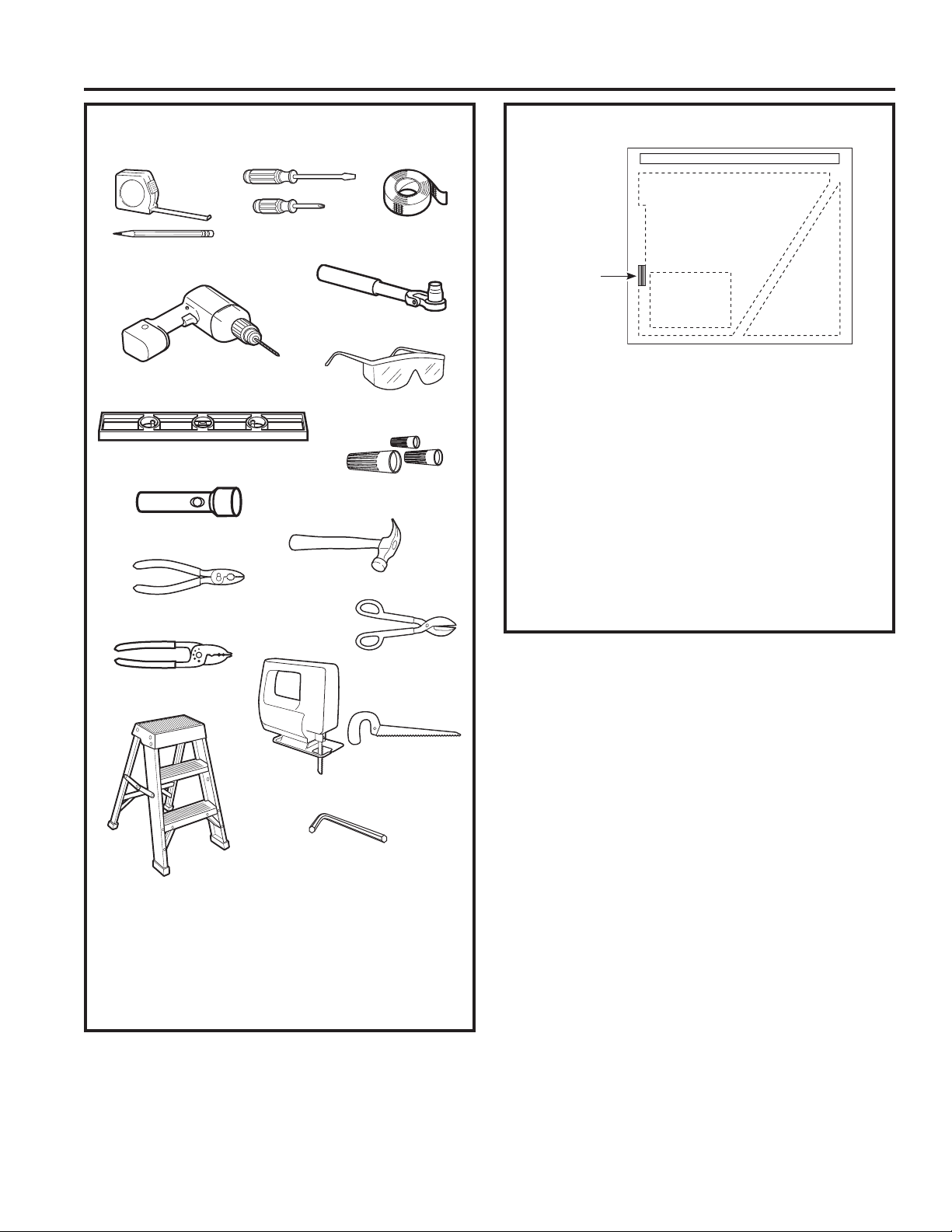
TOOLS AND MATERIALS REQUIRED
(NOT SUPPLIED)
Phillips and Flat blade
Pencil and tape
measure
Electric drill with 1/8” and 3/8” bits
Spirit level
screwdrivers
1/4” pivoting hex socket
UL Listed Wire nuts
Duct tape
Safety glasses
INSTALLATION PREPARATION
Flashlight
Hammer
Pliers
REMOVE THE PACKAGING
Hood
Wood
Mounting
Support
• Remove the small box housing the motor.
• Lift the hood out of the box.
• Remove shipping screws holding the wood
mounting piece to the back side of the hood. Set
aside wood mounting piece and screws for later
installation. Do not discard.
• Remove the “V” shaped carton insert.
• Remove parts package from the “V” shaped
cardboard insert.
• Remove junction box cover and knockout.
• Install strain relief onto back or top of hood.
• Remove all tape and packing material from the
hood, duct transition and motor.
Motor
Shipping Carton
Parts
Package
Tin Snips
Wire Cutter/Stripper
Saber saw or Key Hole Saw
Allen Wrench
Ladder
Additional Materials:
• 120V 60Hz, 15 or 20 Amp, 2 wire with ground.
Properly grounded branch circuit.
• Strain relief for junction box.
• 7” round metal duct or 3-1/4” x 12” rectangular
duct length to suit installation.
12 49-2000061 Rev. 1
Installation Preparation
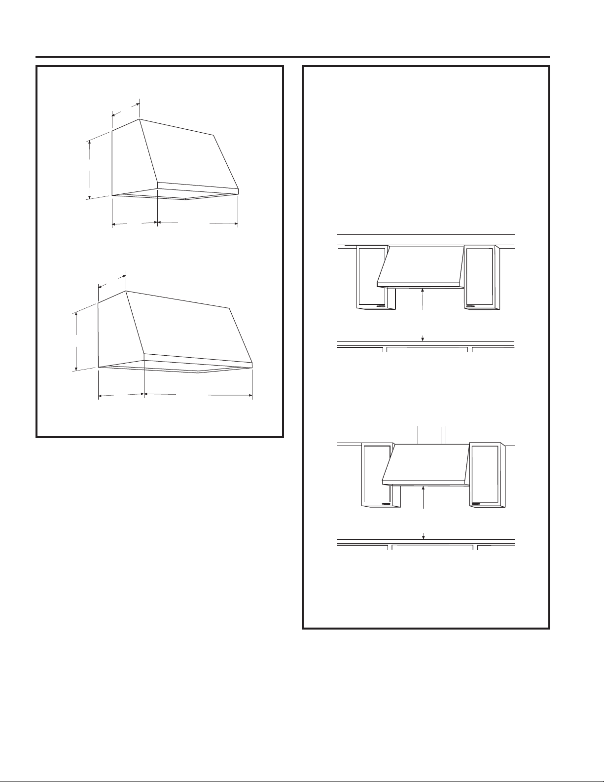
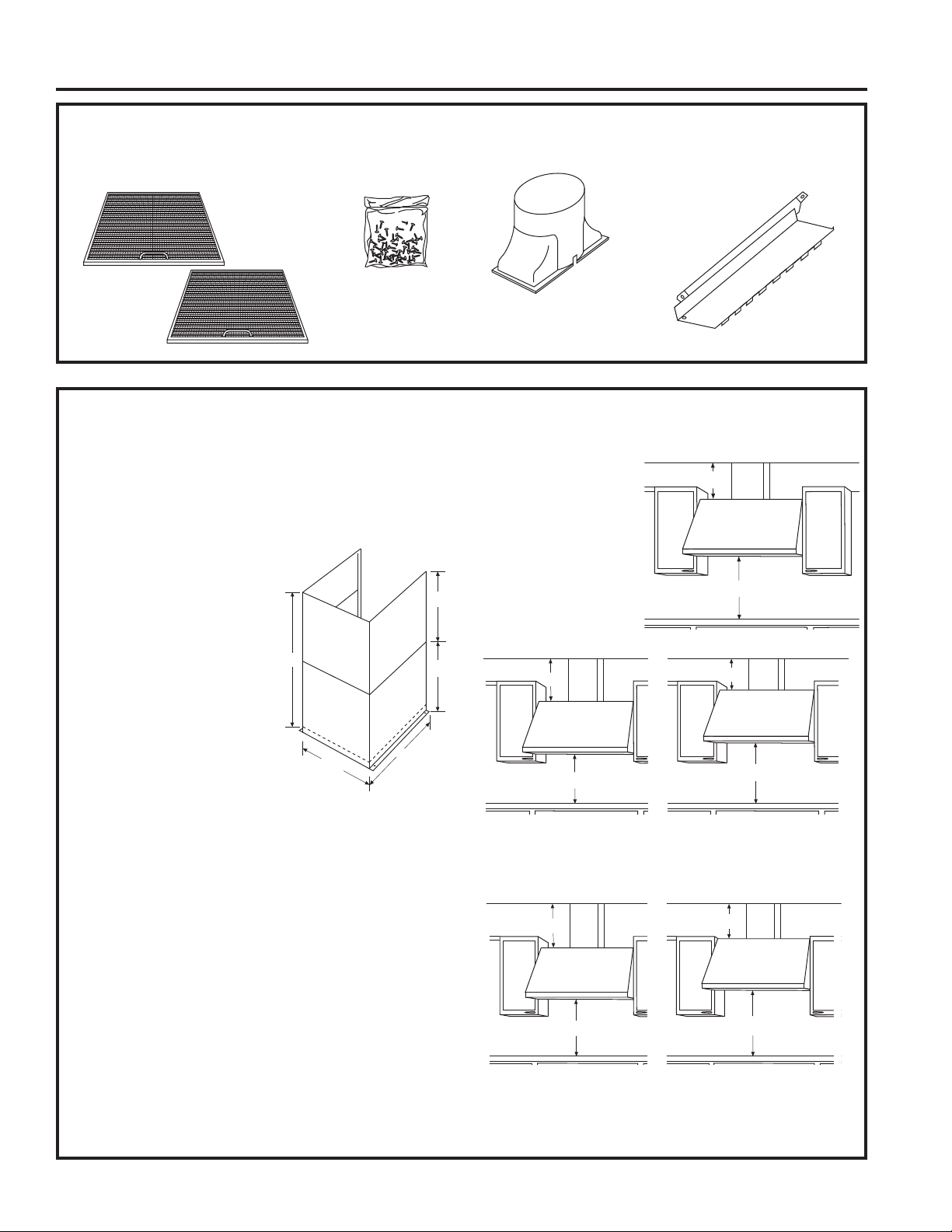
PARTS PROVIDED
Locate the hardware accessory box packed with the hood and check contents.
INSTALLATION PREPARATION
2 Aluminum
Grease Filters
Screws, wall
fasteners, washers
DUCT COVER REQUIREMENTS
We recommend that the vent hood and decorative
duct cover (if used) be on site before final framing
and wall finishing. This will help to accurately locate
studs, ductwork, and electrical service. Read these
instructions to determine if the duct cover accessory
can be used for your installation situation.
Duct Cover Accessory:
• Use the decorative duct
cover to conceal ductwork
running from the top of the
hood to the ceiling.
• The duct cover accessory
22”
consists of 2 pieces. The
outside piece is 12” high,
the inside piece is 22”.
Nested together they are
24” minimum expanding to a
total maximum height of 34”.
11”
• The outside piece can be
used alone to fill a 12” height.
• For heights over 12”, the ceiling bracket must be
installed to secure the cover at the top.
To avoid unsightly gaps, plan the hood installation
height for duct cover use.
• The cover will fit a 12” minimum height from the top of
the hood to the ceiling or 24” minimum and expanding
up to 34” from the top of the hood to the ceiling.
THE DUCT COVER CANNOT BE USED WHEN THE
DISTANCE ABOVE THE TOP OF THE HOOD IS
BETWEEN 12” AND 24”.
12”
12”
12”
Duct Transition
with Damper
Filter
Support
Review the following examples to ensure a trouble free
installation using the duct cover accessory.
8ft. Ceilings: The hood
must be installed at
30” above the cooking
8 ft. Ceiling
12”
surface (or 66” above
the floor). the duct cover
will not fit if the hood
is installed at a lower
or higher height. Use
30”
the outside 12” section,
discard the inside section.
9 ft. Ceiling
30”
24”
24”
30”
9 ft Ceiling: Install the hood 24” min. and up to a
maximum of 30” above the cooking surface. The duct
cover will expand to reach ceiling height.
10 ft. Ceiling
34”
32”
30”
36” Max
10 ft. Ceiling: Install the hood 32” min to 36” max.
above the cooking surface. The duct cover will expand
to a maximum of 34” above the top of the hood to
meet the ceiling.
49-2000061 Rev. 1 13
Installation Preparation
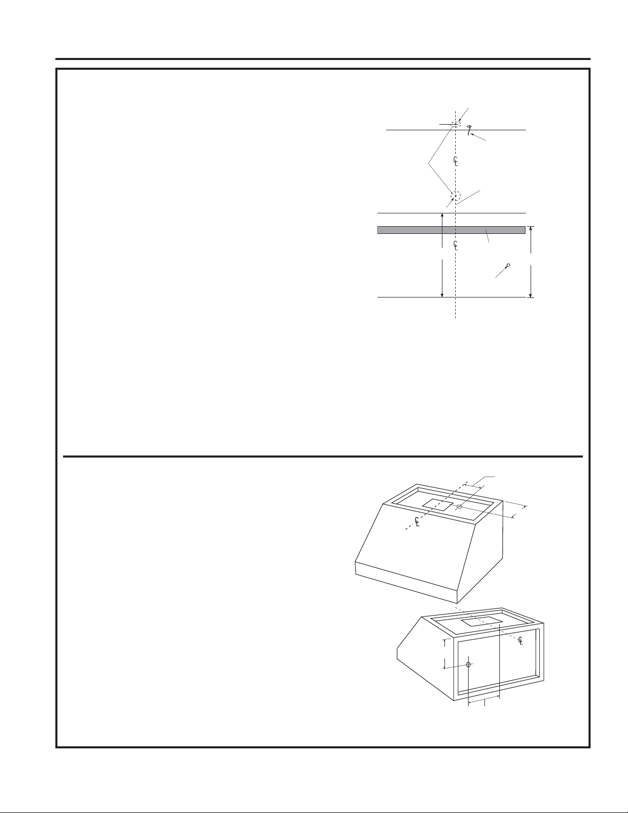
DETERMINE HOOD, DUCTWORK AND WIRING LOCATIONS
• Keep the wood support piece and its screws for later
installation. Do not discard.
• Measure desired distance from the bottom of the hood
to the cooking surface, 24” required minimum and 36”
recommended maximum. Refer to the previous page if
the accessory duct cover will be used.
• Use a level to draw a horizontal line indicating the
bottom of the hood.
• Use a level to draw the cooktop centerline location.
• Measure 15-3/8” up from the horizontal line for the
bottom of the hood. Draw another horizontal line.
• Measure 18” up from the line for the bottom of the
hood, draw another horizontal line to indicate the top
of the hood.
For Vertical (Straight Up) Ducting:
• If venting out the ceiling, extend the centerline
forward on the ceiling.
- Measure 6-7/8” from drywall to mark centerline for
INSTALLATION PREPARATION
a 7-1/2” diameter duct hole on the ceiling.
- If drywall is not present, add drywall thickness to
the 6-7/8” dimension.
Venting Through a Soffit or Upper Cabinet:
• Follow the same procedure for ceiling ducting to cut
the 7-1/2” dia. hole through the top of the cabinet
or soffit.
• See Step 4, page 16 for details to cut opening for
duct transition.
6-7/8” Centerline to Wall
7-1/2” Dia. Hole
FOR WALL VENT
DUCTING
Top of Hood
Bottom of Hood
For Ducting Through Rear Wall:
• Measure the supplied duct transition with any
straight run length of duct used, plus 90” elbow
height. Draw a horizontal line on the wall
intersecting the centerline.
18”
FOR CEILING VENT
DUCTING
Electrical
Centerline 8” Min.
above Top of Hood
Wood
Support
Electrical
15-3/8”
House Wiring Location:
• The junction box is fastened to the back of the hood
on the right side. See illustrations for hood knockout
locations.
NOTE: The junction box can be relocated to the inside
top of the hood.
House wiring may enter the junction box from the rear
or the top of the hood at the right side.
To route house wiring through the ceiling or soffit:
• Cut a hole approximately 1” dia., 5-7/8” forward on
the ceiling; 11-1/8” to the right of the centerline for
30” models or 14-1/8” to the right of the centerline for
36” models.
To route house wiring through the wall:
• Cut a hole approximately 1” dia. 10-1/16” down
from the top of the hood, 11-1/8” to the right of the
centerline for 30” models or 14-1/8” to the right of the
centerline for 36” models.
• Remove top or rear knockout depending on your
installation.
• Install strain relief onto back or top of hood.
14-1/8” for 36” Models
11-1/8” for 30” Models
5-7/8”
Knockout
Locations
10-1/16”
14-1/8” for 36” Models
11-1/8” for 30” Models
14 49-2000061 Rev. 1
Installation Instructions
INSTALLATION INSTRUCTIONS
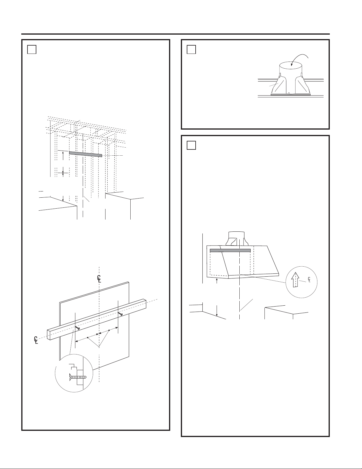
1
INSTALL HOOD SUPPORT
IMPORTANT: Framing must be capable of
supporting 100 lbs.
• Locate at least 2 vertical studs at the wood
mounting location by tapping drywall with a
hammer or use a stud finder.
• Center the supplied wood horizontal support, left
to right, and below the marked line.
7” Min. Opening for Ductwork
Wood Support
15-3/8”
24” Required
Minimum and 36”
Recommended
Maximum
Centerline of
Installation Space
• Drill 1/8” pilot holes through the support, drywall
and into the studs. Secure the support to 2 or
more vertical studs with supplied wood screws.
IMPORTANT: Screws must penetrate at least 1-1/2”
into vertical studs. Countersink screws into support.
2
INSTALL TRANSITION
IMPORTANT:
Remove shipping
tape from damper and
check that damper
moves freely.
Duct
Transition
Remove
Shipping
Tape on
Damper
Top of
Hood
• Place the transition piece over the hood exhaust.
Secure transition to hood with 4 screws provided.
• Use duct tape to seal the connection.
3
INSTALL HOOD ONTO WALL
• Lift the hood and place over the wood support.
The top keyhole slots in the hood should engage
the protruding mounting screws. Allow the hood to
slide down into position.
• Pull house wiring through knockout at the rear or
top of the hood.
• Check to be sure the hood is level and centered.
The arrow shaped cutout in the back of the hood
allows viewing the marked centerline.
• Remove cover from junction box.
24” Required
Minimum and 36”
Recommended
Maximum
Centerline of
Installation Space
Cutout
Drill Bottom Mounting Hole Locations
• Drill 1/8” pilot holes into the two lower mounting
holes. Enlarge the holes if they do not enter studs
13-1/16”
1/4” gap
to 3/8”. Tap anchors for wall fasteners into bottom
holes. Install screws by hand into the fasteners
to allow anchors to expand against the wall.
Remove screws.
• Using two large flat washers (supplied), install
wood screws or wall fastener screws, loosely, into
lower mounting holes. Do not tighten.
• Install mounting screws in the center of the wood
support, 13-1/6” from the centerline. The screws
should protrude forward 1/4”. This 1/4” gap will
provide clearance to hang the hood.
• Check hood level. Tighten upper screws. Tighten
lower mounting screws.
• For additional security, drive screws through the
original wood support screw holes in the back of
the hood.
49-2000061 Rev. 1 15
 Loading...