

Cadet The Perfectoe UC102, The Perfectoe UC101 Owner's Manual
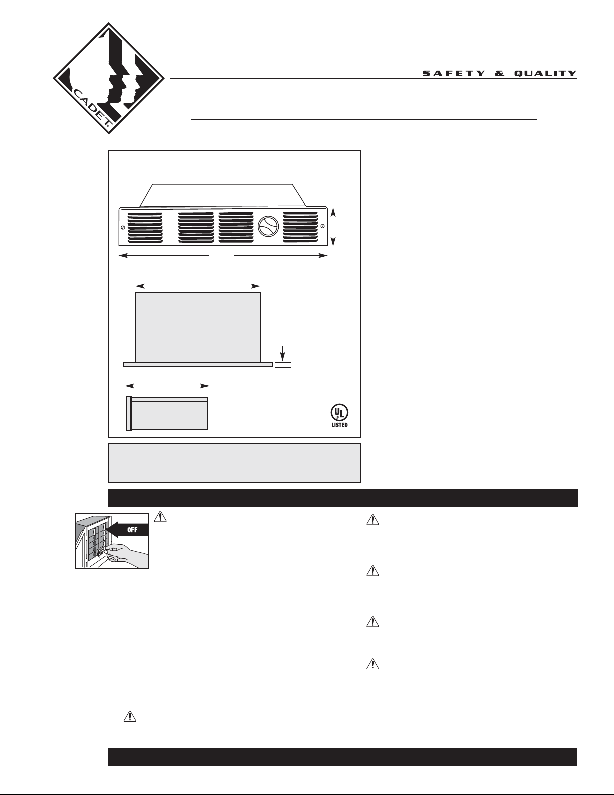
8¼”
21cm
The Perfectoe
Front
18”
45.7cm
14½”
36.8cm
Top
The Perfectoe
OWNER’S GUIDE
Features & Benefits
•
Thermal Safeguard
•
High temperature manual reset:
turns off heater if normal operating
temperatures are exceeded
3½”
8.9cm
¼”
.6cm
•
Rugged steel-finned element
•
Ideal for bathrooms and kitchens
•
Low profile for rooms with limited space
•
Two-year extended warranty
•
Single pole or double pole field mount
thermostat kit available
•
Black or white powder coat paint for
a durable finish
MODELS
The Perfectoe
UC072
UC102
UC101
Side
TOOLS REQUIRED:
Phillips Screwdriver
Straight Screwdriver
Wire Strippers
Utility Knife
1
/2” Wood Screws
(2) 1
(3) Insulated Wire Connectors
(1) Strain Relief Connector
IMPORTANT INSTRUCTIONS
WARNING
Turn the electrical power off at the electrical
panel board (circuit breaker or fuse box) and
lock or tag the panel board door to prevent
someone from turning on power while you are
working on the heater. Failure to do so could
result in serious electrical shock, burns, or
possible death.
1. Read all instructions before using this heater.
2. Read all information labels. Verify that the electrical supply
wires are the same voltage as the heater.
3. All electrical work and materials must comply with the
National Electric Code (NEC), the Occupational Safety and
Health Act (OSHA), and all state and local codes.
4. Connect the grounding pigtail (copper wire) provided in the
wall can to the supply ground wire.
5. If you need to install a new circuit or need additional wiring
information, consult a qualified electrician.
6. Protect electrical supply from kinks, sharp objects, oil,
grease, hot surfaces or chemicals.
7. WARNING
Overheating or fire may occur. DO NOT install the heater in
a floor, behind doors, or outdoors.
* For installations above 7000 feet, highest
wattage recommended is 750 watts.
8. WARNING
Fire or explosion may occur. Heater has hot and arcing or
sparking parts inside. Do not install heater in any area
where combustible vapors, gases, liquids, or excessive lint
or dust are present.
9. WARNING
Burn Hazard. This heater is hot when in use. To avoid burns,
do not let bare skin touch hot surfaces. Use extreme caution
when any heater is used by or near children or invalids and
whenever the heater is left operating unattended.
10. WARNING
Risk of Electrical Shock. Keep all foreign objects out of
heater. Do not operate after heater malfunctions or has
been dropped or damaged in any manner.
11. WARNING
Risk of Fire. Do not block heater. Heater must be kept clear
of all obstructions: a minimum of 3 feet in front, 6 inches on
both sides. Heaters must be kept clean of excessive lint, dirt
and debris. (See Maintenance Instructions).
12. Use this heater only as described in this manual. Any other
use not recommended by the manufacturer may cause fire,
electrical shock, or injury to persons.
www.cadetco.com Tel: 360-693-2505 P.O. Box 1675 Vancouver, WA 98668-1675
SAVE THESE INSTRUCTIONS
READ ALL
INSTRUCTIONS
AND SAFETY
INFORMATION
Installation Instructions
Part One
PLACEMENT: Read IMPORTANT INSTRUCTIONS for important safety requirements. For best results,
install heater beneath a cabinet in the toe kick area. Install the Perfectoe (Model UC) horizontally. Do not
install the UC heater in the floor. Headers and bracing are not necessary. Heater must be installed per the
directions indicated on the lid. See clearance requirements for additional placement instructions. Install
at least 6” from the inside corner and/or vertical adjacent surfaces.
CONTROLS: A thermostat is required. A Cadet electronic thermostat is recommended for ultimate control
and comfort. Optional single or double pole field mount thermostat kits are also available.
IMPORTANT!
It is extremely
important that
you verify the
electrical supply
wires are the same
voltage as the
heater (i.e. 120 volt
heater to 120 volt
power supply and
240 volt heater to
240 volt power
supply). If
replacing an
existing heater,
check the labels of
the old heater and
replace using the
same voltage.
Hooking a 240 volt
heater to a 120 volt
power supply will
drastically reduce
the heater’s
output. Hooking a
120 volt heater to a
240 volt power
supply will destroy
the heater.
Connecting your
heater to an
incompatible power
supply will void the
warranty.
STEP 1 Turn the Electrical Power OFF
Turn the electrical power off at the electrical
panel board (circuit breaker or fuse box) and lock
or tag the panel board door to prevent someone
from turning on power while you are working
on the heater.
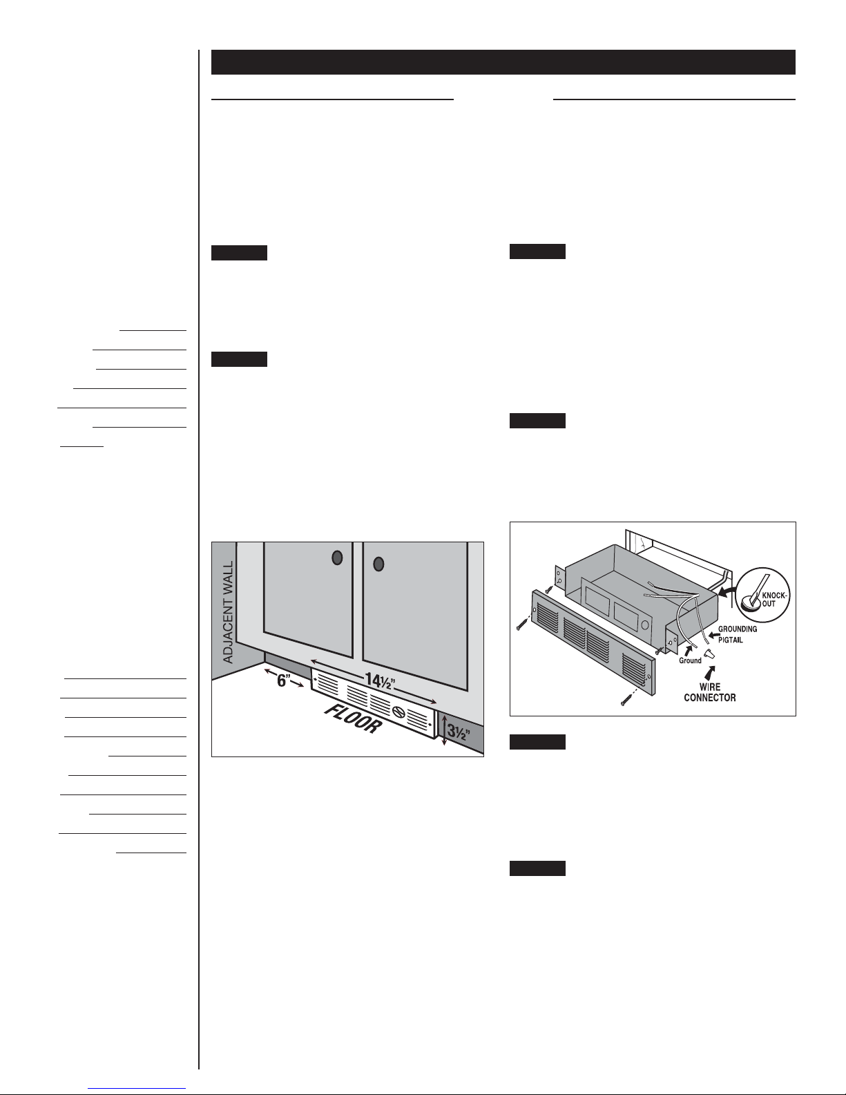
STEP 2 Determine Area of Installation
The UC Series heater REQUIRES A MINIMUM
distance of 6 inches from adjacent surfaces
(See Figure 1). However, Cadet RECOMMENDS
12 inches from all adjacent surfaces for longer
and cleaner performance. Heaters must be
spaced at least 3 feet apart.
For installation in an existing wall/cabinet, cut
a rough opening 14½ inches wide by 3½ inches
high. Opening must be 8½ inches deep and
6 inches from adjacent wall.
Figure 1
WARNING! Vinyl floor manufacturers warn
that some vinyl may discolor from temperatures
in excess of 110° F. See your vinyl floor
manufacturer for temperature specifications
for your vinyl floor covering.
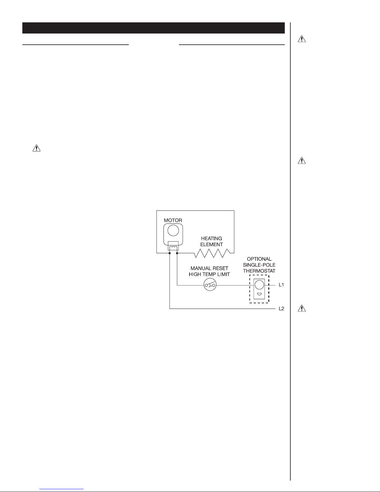
STEP 3 Route Supply Wires
For wall thermostat applications, route supply wire
from circuit breaker to thermostat to rough
opening. For models with an optional field mount
thermostat kit, route supply wire from circuit
breaker to rough opening. Allow enough wire to
extend 12 inches beyond the opening. Place heater
lid aside. Remove the knockout and attach the
supply wire with a strain relief connector, leaving
6 inches wire lead for later use (See Figure 2).
STEP 4 Connect Supply Wires
Connect the supply ground wire to the green
grounding pigtail provided (See Figure 2). Connect
each supply wire to one heater wire with wire
connectors. Note: All wire connections must be
made inside the heater.
Figure 2
STEP 5 Mount the Heater
Reinstall heater lid and attach using four screws
provided. Slide heater into opening. Fasten heater
to cabinet with screws (not provided) going
through the lower holes located on the flanges.
Fasten grill to heater with screws provided going
through the upper holes located on the flanges.
STEP 6 Turn the Electrical Power ON
Turn the electrical power back on at the electrical
panel board (circuit breaker or fuse box).
2
Operation and Maintenance
Part Two
How to operate your heater
1. Once installation in complete and power has
been restored turn the thermostat knob fully
clockwise.
2. When the room reaches your comfort level, turn
the thermostat knob counterclockwise until the
heater turns off. The heater will automatically
cycle around this preset temperature.
3. To reduce the room temperature, turn the
knob counterclockwise. To increase the room
temperature, turn the knob clockwise.
Maintenance
As needed, or every six months minimum.
1. WARNING! Before removing grill, turn the
electrical power off at the electrical panel
board (circuit breaker or fuse box). Lock or tag
the panel board door to prevent someone from
accidentally turning the power on while you
are working on the heater. Failure to do so
could result in serious electrical shock, burns,
or possible death.
2. It is important that you verify power has been
turned off and no power is going to the heater
before proceeding. Circuit breakers are often
not marked correctly and turning the wrong
breaker off could mean electricity is flowing to
the heater, even if the heater does not appear
to be working. If you are uncomfortable working
with electrical appliances, unable to follow
these guidelines, or do not have the necessary
equipment, consult a qualified electrician.
3. Once you verify the power has been turned
off correctly, proceed to the next step.
4. Remove thermostat knob, if equipped.
Remove the screws and take off grill.
5. Wash grill with hot, soapy water and dry
immediately.
6. If present, remove the screws securing the
heater assembly to the opening, then pull
heater out of opening.
7. Remove the four screws securing the lid to the
top of the heater assembly, remove lid.
8. Thoroughly vacuum accumulated dust, lint
or other debris from blower wheel and heater
outlet. Important: Be careful not to damage
the blower wheel, and do not allow the blower
wheel to spin freely when vacuuming.
9. Install lid and slide heater assembly back into
opening. Secure heater assembly to opening,
then install grill and thermostat knob (if equipped).
10. Restore power to heater at circuit breaker
panel or fuse box, then test heater operation
by turning thermostat on and/or adjusting
to a higher temperature.
About the Manual Reset Temperature Limit Control
The heater is protected by a temperature-limit
control. The manual reset temperature limit control
is designed to open the heater circuit when
excessive operating temperatures are detected.
The problem must be assessed and the limit must
be reset to resume operation.
Resetting the Manual Reset Temperature
Limit Control
If the manual reset limit control has opened
the heater circuit due to excessive operating
temperatures, the heater will not work until
the manual reset limit button is pressed. After
allowing the unit to cool for at least 15 minutes
and resolving the problem causing the limit to trip
(typically heater is blocked or needs cleaning),
use a narrow object such as a ball-point pen
to access the manual reset button through the
heater grill. Press FIRMLY, and be sure to listen
and feel for a click, indicating it has been reset.
Wiring Diagram
UC
With inbuilt single pole thermostat
WARNING
Risk of Electrical
Shock. Connect
grounding lead to
grounding wire
provided. Keep all
foreign objects out
of heater.
WARNING
Risk of Fire.
Heater must be
kept clear of all
obstructions: a
minimum of 3 feet
in front; 6 inches
on both sides.
Heaters must be
kept clean of lint,
dirt and debris.
WARNING
Turn the electrical
power off at the
electrical panel
board (circuit
breaker or fuse
box) and lock or
tag the panel board
door to prevent
someone from
turning on power
while you are
working on the
heater. Failure to
do so could result
in serious
electrical shock,
burns, or possible
death.
3
 Loading...