


The Com-Pak™ Plus
OWNER’S GUIDE
|
The Com-PakTM Plus Model C |
|
||||
Side |
Grill Front |
Wall Can Side |
|
|
||
|
12” |
111/2” |
|
10” |
Wall Can Bottom |
|
|
29.21 |
|
||||
|
30.48 |
|
25.4 |
13/4” |
11/4” |
|
|
|
|
|
|||
|
|
31/4” |
|
|
4.45 |
3.18 |
|
|
11/4” |
|
|
|
|
|
|
8.26 |
|
|
4” |
|
|
|
|
3.18 |
3” |
||
|
|
|
|
|
10.16 |
|
|
|
|
|
|
7.62 |
|
|
|
|
|
|
|
|
|
9” |
|
|
|
77/8” |
|
|
22.86 |
|
|
|
20.00 |
|
|
The Com-PakTM Twin Plus Model CT |
|
||||
Side |
Grill Front |
|
|
Wall Can Side |
||
|
|
|
12” |
111/8” |
10” |
|
|
|
|
30.48 |
28.26 |
25.4 |
|
|
161/4” |
|
|
|
|
|
|
41.27 |
|
|
|
|
|
|
3” |
|
4” |
Wall Can |
|
|
|
7.62 |
|
10.16 |
Bottom |
|
|
|
141/2” |
|
|
|
|
|
|
36.83 |
|
|
|
|
|
TOOLS REQUIRED: |
Utility Knife |
|
Phillips Screwdriver |
4 |
11/2“ Wood Screws |
Straight Screwdriver |
3 |
Insulated Wire Connectors |
Wire Strippers |
1 |
Strain Relief Connector |
|
|
|
Features & Benefits
•Primary and secondary thermal safeguards
•Commercial grade high temperature manual reset
•Over temperature one-time thermal device
•Nichrome element wrapped around mica insulators for durability
•Powder coat paint process eliminates sharp cutting edges
•Two year extended warranty
•Wall can designed for ease of installation
•Factory tested
MODELS
The Com-PakTM Plus |
|
|
|
C051 |
*C051T |
C152 |
*C152T |
C052 |
*C052T |
C202 |
*C202T |
C072 |
*C072T |
C208 |
*C208T |
C102 |
*C102T |
C101 |
*C101T |
C122 |
*C122T |
C151 |
*C151T |
The Com-PakTM Twin Plus |
|
|
|
CT252 |
*CT252T |
CT102 |
|
CT302 |
*CT302T |
|
|
CT402 |
*CT402T |
|
|
CT408 |
*CT408T |
|
|
*Standard built-in thermostat is single pole and has no “OFF” position
IMPORTANT INSTRUCTIONS
 WARNING
Turn the electrical power off at the electrical panel board (circuit breaker or fuse box) and lock or tag the panel board door to prevent someone from turning on power while you are working on the heater. Failure to do so could result in serious electrical shock, burns, or possible death.
1.Read all instructions before using this heater.
2.Read all information labels. Verify that the electrical supply wires are the same voltage as the heater.
3.All electrical work and materials must comply with the National Electric Code (NEC), the Occupational Safety and Health Act (OSHA), and all state and local codes.
4.Connect the grounding pigtail (copper wire) provided in the wall can to the supply ground wire.
5.If you need to install a new circuit or need additional wiring information, consult a qualified electrician.
6.Protect electrical supply from kinks, sharp objects, oil, grease, hot surfaces or chemicals.
7. WARNING
Overheating or fire may occur. Do not install the heater in a floor, behind doors, or outdoors.
8. WARNING
Fire or explosion may occur. Heater has hot and arcing or sparking parts inside. Do not install heater in any area where combustible vapors, gases, liquids, or excessive lint or dust are present.
9. WARNING
Burn Hazard. This heater is hot when in use. To avoid burns, do not let bare skin touch hot surfaces. Use extreme caution when any heater is used by or near children or invalids and whenever the heater is left operating unattended.
10. WARNING
Risk of Electrical Shock. Keep all foreign objects out of heater. Do not operate after heater malfunctions or has been dropped or damaged in any manner.
11. WARNING
Risk of Fire. Do not block heater. Heater must be kept clear of all obstructions: a minimum of 3 feet in front, 6 inches above and on both sides. Heaters must be kept clean of excessive lint, dirt and debris. (See Maintenance Instructions).
12.Use this heater only as described in this manual. Any other use not recommended by the manufacturer may cause fire, electrical shock, or injury to persons.
SAVE THESE INSTRUCTIONS
360-693-2505 Fax: 360-694-8668 P.O. Box 1675 Vancouver, WA 98668-1675
READ ALL INSTRUCTIONS AND SAFETY INFORMATION
IMPORTANT!
It is extremely important you verify that the electrical supply wires are the same voltage as the heater (i.e. 120 volt heater to 120 volt power supply and 240 volt heater to 240 volt power supply). If replacing an existing heater, check the labels of the old heater and replace using the same voltage. Hooking a 240 volt heater to a 120 volt power supply will drastically reduce the heater’s output. Hooking a 120 volt heater to a 240 volt power supply will destroy the heater. Connecting your heater to an incompatible power supply will void the warranty.
2
Installation Instructions
Part One
PLACEMENT: Install The Com-Pak Plus (Model C) vertically (recommended) or horizontally. Model C may be installed in the ceiling (for models up to 1500W maximum. See ceiling mount instructions.) The Com-Pak Twin Plus (Model CT) must be installed with the arrows in the wall can pointing upwards.
THERMOSTAT: A thermostat is required for models without a built-in thermostat. A Cadet Electronic Thermostat or Cadet Dual Diaphragm Thermostat is recommended for ultimate control and comfort.
How do I install for
new construction walls?
STEP 1 Mount The Wall Can
The C Series REQUIRES A MINIMUM distance of
6 inches from adjacent surfaces and 41/2 inches from the floor (See Figure 4) and the CT Series REQUIRES A MINIMUM distance of 6 inches from adjacent surfaces and 41/2 inches from the floor (See Figure 5). However, Cadet RECOMMENDS 12 inches from all adjacent surfaces and 12 inches above the floor for longer and cleaner performance. Heaters must be spaced at least 3 feet apart.
Review the wall can label for correct direction (as noted by the UP arrows) before mounting the wall can in the opening. In the VERTICAL mounting
position the elements of the heater assembly will be at the top, in the HORIZONTAL mounting position the elements of the heater assembly will be to the left.
Model C: Secure the wall can to the stud with
2 screws (See Figures 1 & 2). As an option, the rubber shim provided may be attached to side of wall can to square the wall can to the stud.
Model CT: Secure the wall can to studs on both sides
with 4 screws.
Figure 1
Face of wall can must extend 1/2 inch or 5/8 inch from face of stud to allow for thickness of sheetrock.
Figure 2
Attach wall can to stud with screws. (Model C shown)
STEP 2 Route Supply Wires
Route supply wire from circuit breaker to thermostat to wall can. For models with built-in thermostat, route supply wire from circuit breaker to wall can. Remove a knockout and attach the supply wire with a strain relief connector leaving 10 inches wire lead for later use. Connect supply ground wire to grounding pigtail in wall can (See Figure 3). Proceed to PART TWO.
Figure 3
How do I install in an existing wall?
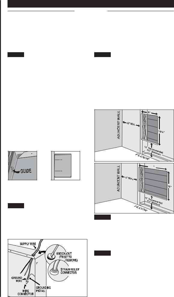
STEP 1 Cut Hole In Wall
Model C: Cut a hole 8 inches wide by 101/4 inches high next to wall stud. The C Series REQUIRES
A MINIMUM distance of 6 inches from adjacent surfaces and 41/2 inches from the floor. However, Cadet RECOMMENDS 12 inches from all adjacent surfaces and 12 inches from the floor (See Figure 4).
Model CT: Cut a hole 145/8 inches wide by 10 inches high next to wall stud. The CT Series REQUIRES
A MINIMUM distance of 6 inches from adjacent surfaces and 41/2 inches from the floor. However, Cadet RECOMMENDS 12 inches from all adjacent surfaces and 12 inches from the floor (See Figure 5).
Figure 4 |
|
Model C |
|
14 |
5 |
/8 |
Figure 5
Model CT
STEP 2 Route Supply Wires
Route supply wire from circuit breaker to thermostat to wall can. For models with built-in thermostat, route supply wire from circuit breaker to wall can. Remove a knockout and attach the supply wire with a strain relief connector leaving 10 inches wire lead for later use (See Figure 3). Connect supply ground wire to grounding pigtail in wall can.
STEP 3 Mount Wall Can
Review the wall can label for correct direction (as noted by the UP arrows) before mounting the wall can in the opening. In the VERTICAL mounting
position the elements of the heater assembly will be at the top, in the HORIZONTAL mounting position the elements of the heater assembly will be to the left.
Insert wall can into opening. Keeping wall can flush with wall, secure Model C to wall stud with 2 screws and Model CT to both wall studs with 4 screws. Proceed to PART TWO.

Installation Instructions
Part One
How do I install for ceiling mount?
(for models up to 1500 Watts maximum)
STEP 1 Mount the Wall Can
The C Series REQUIRES A MINIMUM distance of
6 inches from all adjacent surfaces. However, Cadet RECOMMENDS 12 inches from all adjacent surfaces for longer and cleaner performance. Important:
Do not mount the heater in low-density fiberboard or false ceilings.
Secure the wall can to studs/rafters on opposite sides (See Figures 6 and 7) with 4 screws (not provided). The face of the wall can must extend 1/2 or 5/8 inches from face of rafters to allow for thickness of sheetrock.
Insulating materials may touch the wall can however, “blown-in” insulation is not recommended as it could be drawn into the heater through gaps behind the grill. For ceiling installation, the wall can must be boxed in with wood on all sides and back to prevent dust from entering the heater through the ceiling cavity.
STEP 2 Route Supply Wires
Route supply wire from circuit breaker to thermostat to wall can. Models with a built-in thermostat are not recommended for ceiling mount. Remove a knockout in the wall can and attach the supply wire with a strain relief connector leaving 10 inches wire lead for later use (See Figure 3). Connect supply ground wire to grounding pigtail in wall can. Proceed to Part Two.
6” |
Min. |
|
|
Figure 6 |
|
6” |
Min. |
|
|
Figure 7 |
|
Part Two
After you have followed all instructions in PART ONE you are ready to install the heater assembly.
How do I insert the heater assembly into the wall can?
STEP 1 Install Heater Assembly
Turn heater assembly upside-down (element down) with motor facing you. Connect the supply wires to the heater wires with wire connectors (See Figure 8). Now rotate the heater so the element and fan are facing you (with the element ‘up’). Insert the bottom edge of the heater assembly into the tabs in the bottom lip of the wall can (See Figure 9).
Important: Push wires into bottom of wall can during insertion. Be sure that supply wires are not caught between motor and wall can. Attach assembly at top with screw provided.
STEP 2 Install Grill
Secure grill with the screws provided. If you have a built-in thermostat model, slide thermostat knob onto shaft. Turn power on at the electrical panel board.
Warranty is void if any material is sprayed on the element or blower.
SUPPLY |
|
WIRES |
GROUNDING |
WIRE |
PIGTAIL |
CONNECTOR |
WIRE |
|
CONNECTOR |
HEATER WIRES |
BACK |
|
|
|
MOTOR |
Figure 8
TOP |
Figure 9 |
WARNING
Risk of Electrical Shock. Connect grounding lead
to grounding wire provided. Keep
all foreign objects out of heater.
WARNING Risk of Fire. Heater must be kept clear of
all obstructions: a minimum
of 3 feet in front; 6 inches on both sides and above. Heaters must be kept clean of lint, dirt and debris.
WARNING Turn the electrical power off at the electrical panel board (circuit breaker or fuse box) and lock or
tag the panel board door to prevent someone from turning on power while you are working on the heater. Failure to do so could result in serious electrical shock, burns, or possible death.
3
 Loading...