

Cadet The Com-Pak CBC132TW, The Com-Pak CB132T Owner's Manual
OWNER’S GUIDE FOR MULTI-WATT MODELS
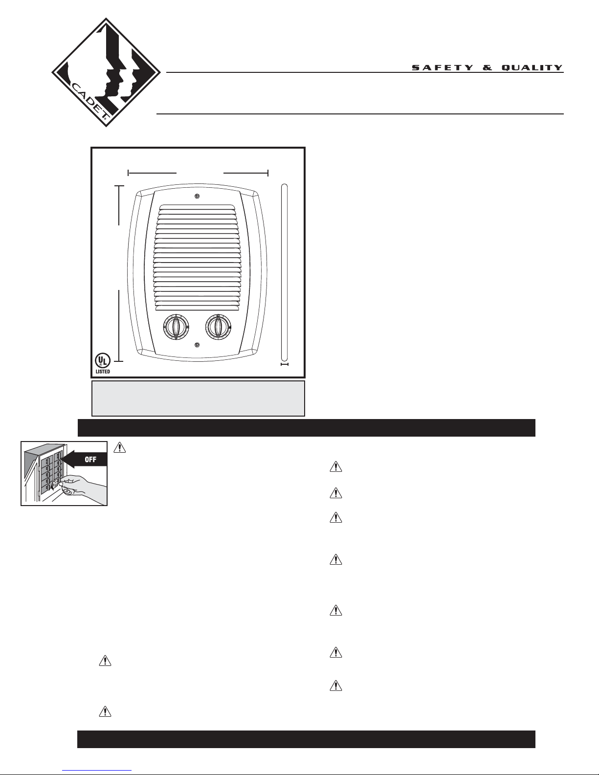
The Com-Pak™ Bath Heater
■ Primary and secondary thermal
safeguards
•
High temperature manual reset
•
Over temperature one-time thermal
device
■ Commercial grade steel element painted
to resist rusting
■ Built-in controls
• Single pole thermostat • 60 minute timer
■ Powder coat paint process eliminates
sharp cutting edges
■ Three year extended warranty on
element and motor.
■ Factory tested
■ Multi-Watt
•
1300–800–500 at 240 Volt AC
•
975–600–375 at 208 Volt AC
Models: The Com-Pak Bath Heater CBC132TW and CB132T
Features & Benefits
SAVE THESE INSTRUCTIONS
IMPORTANT INSTRUCTIONS
Tools Required:
Phillips Screwdriver
Straight Screwdriver
Wire Strippers
Utility Knife
4 1
1
/2" Wood Screws
3 Insulated Wire Connectors
1 Strain Relief Connector
WARNING
Turn the electrical power off at the electrical panel
board (circuit breaker or fuse box) and lock or tag
the panel board door to prevent someone from
turning on power while you are working on the
heater. Failure to do so could result in serious
electrical shock, burns, or possible death.
1. Read all instructions before using this heater.
2. Read all information labels. Verify that the electrical
supply wires are the same voltage as the heater.
3. All electrical work and materials must comply with the
National Electric Code (NEC), the Occupational Safety
and Health Act (OSHA), and all state and local codes.
4. Connect the grounding pigtail (copper wire) provided in
the wall can to the supply ground wire.
5. If you need to install a new circuit or need additional
wiring information, consult a qualified electrician.
6. Protect electrical supply from kinks, sharp objects, oil,
grease, hot surfaces or chemicals.
7. WARNING
Overheating or fire may occur. DO NOT install the heater
in a floor, in the ceiling, below a towel bar, behind a door,
or anywhere the air discharge may be blocked in any
manner.
8. WARNING
Fire or explosion may occur. DO NOT install heater in any
area where combustible vapors, gases, liquids, or
excessive lint or dust are present.
9. WARNING
DO NOT install where heater is likely to get wet.
10. WARNING
Heater must be connected to a GFCI protected branch circuit.
11. WARNING
Burn Hazard. This heater is hot when in use. To avoid burns,
do not let bare skin touch hot surfaces. Use extreme
caution when any heater is used by or near children or invalids.
12. WARNING
Risk of Electrical Shock. DO NOT install the heater
directly above bathtub or sink. DO NOT install in shower
stall area (Manufacturer recommends a minimum 2 foot
clearance).
13. WARNING
Risk of Electrical Shock. Connect grounding lead to
grounding wire provided. Keep all foreign objects out of
heater.
14. WARNING
Risk of Electrical Shock. Never place a switch where it can
be reached from the tub or shower enclosure.
15. WARNING
Risk of Fire. Do not block heater. Heater must be kept clear of
all obstructions: a minimum of 3 feet in front, 6 inches above
and on both sides. Heaters must be kept clean of lint, dirt and
debris. (See Maintenance Instructions).
360-693-2505 Fax: 360-694-8668 P.O. Box 1675 Vancouver, WA 98668-1675
The Com-Pak™ Bath Heater
1/2” Depth
10” Width
12 5/8” Height
P.2
Installation Instructions
How do I install for
new construction?
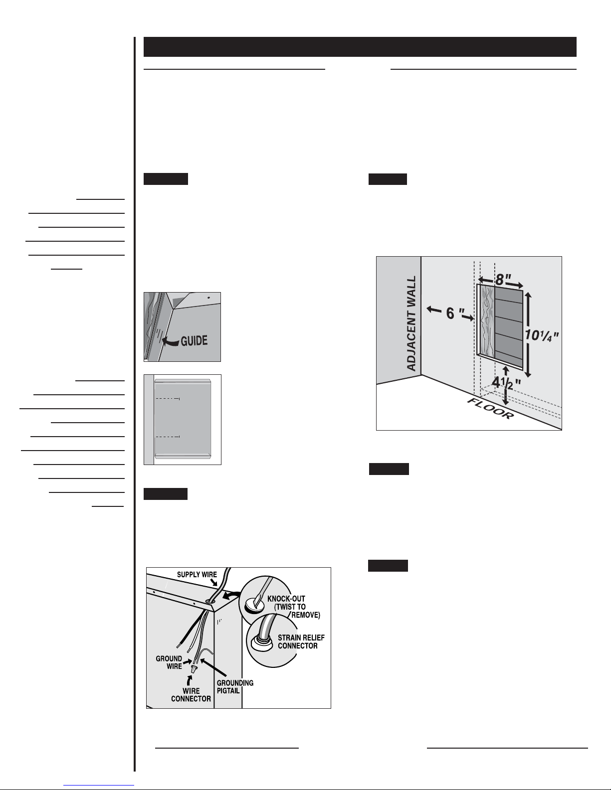
Figure 1
Face of wall can must extend
1
/2 inch or 5/8 inch from face of
stud to allow for thickness of
sheetrock.
The CB Series heater REQUIRES A MINIMUM distance
of 6 inches from adjacent surfaces and 4
1
/2 inches from
the floor. However, Cadet RECOMMENDS 12 inches
from all adjacent surfaces and 12 inches above the floor
for longer and cleaner performance. Heaters must be
spaced at least 3 feet apart.
Secure the wall can to the stud with 2 screws (See
Figures 1 & 2). As an option, the rubber shim provided
may be attached to side of wall can to square the wall
can to the stud.
STEP 1
Mount The Wall Can
How do I install in
an existing wall?
Cut a hole 8 inches wide by 101/4 inches high next to a
wall stud. This heater REQUIRES A MINIMUM distance
of 6 inches from adjacent wall surface and 41/2 inches
from the floor. However, Cadet RECOMMENDS 12 inches
from all adjacent wall surfaces and 12 inches from the
floor (See Figure 4).
STEP 1
Cut Hole In Wall
Route the supply wire from circuit breaker to heater.
Remove a knockout and attach the supply wire with a
strain relief connector, leaving 10 inches wire lead for
later use. Connect supply ground wire to grounding
pigtail in wall can (See Figure 3). Proceed to PART
TWO.
STEP 2
Connect Supply Wires
Figure 2
Attach wall can to stud with
screws through holes provided
in wall can.
Figure 3
Figure 4
Model CB
READ ALL
INSTRUCTIONS
AND SAFETY
INFORMATION
IMPORTANT!
It is extremely
important you verify
that the electrical
supply wires are the
same voltage as the
heater (240 volt
heater to 240 volt
power supply). If
replacing an existing
heater, check the
labels of the old
heater and replace
using the same
voltage. Hooking a
240 volt heater to a
120 volt power supply
will drastically
reduce the heater
's
output. Hooking a 120
volt heater to a 240
volt power supply
will destroy the
heater.
Connecting your
heater to an
incompatible power
supply will void the
warranty.
Part One
PLACEMENT: Install the Com-Pak Bath Heater (Model CB) vertically. Heater is not approved for horizontal or ceiling
mount applications.
CONTROLS: A built-in single pole thermostat and 60 minute timer. (Note: Do not use with a wall thermostat).
Route supply wire from circuit breaker directly to heater.
Remove a knockout and attach the supply wire with a
strain relief connector, leaving 10 inches wire lead for
later use (See Figure 3). Connect supply ground wire to
grounding pigtail supplied in wall can.
STEP 2
Connect Supply Wires
Insert wall can into opening; keeping wall can flush with
wall surface. Secure can to wall stud with 2 screws
through holes provided in can.
Proceed to PART TWO
Mount The Wall Can
STEP 3
Proceed to Part Two
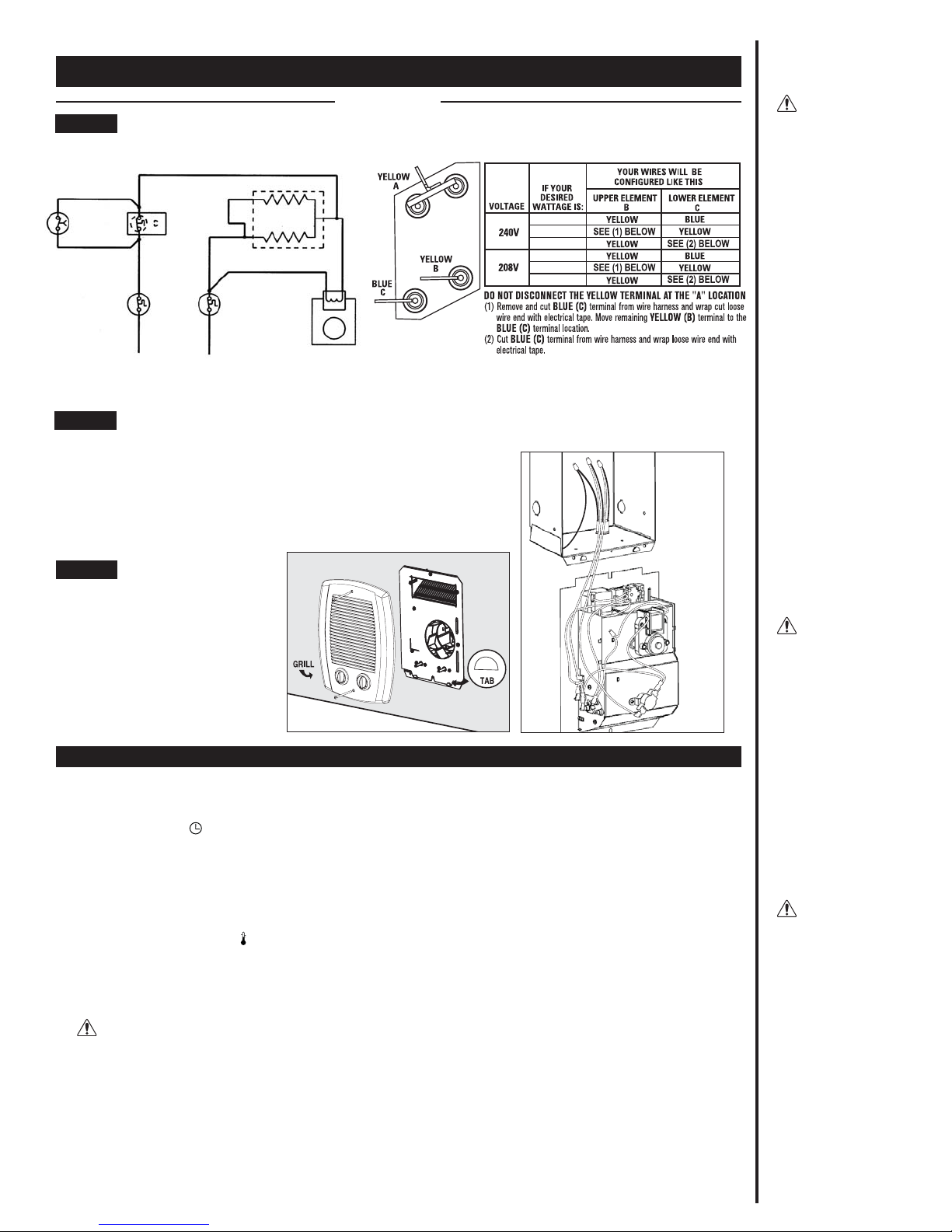
Figure 6a
Installation Instructions
How do I insert the heater assembly into the wall can?
Turn heater assembly upside down (element down with motor facing you).
Connect the supply wires to the heater wires with connectors (See Figure 6b).
Now rotate the heater so the element and the fan are facing you. The element
should be at the top.
Part Two
WARNING
Turn the electrical
power off at the
electrical panel
board (circuit
breaker or fuse
box) and lock or
tag the panel board
door to prevent
someone from
turning on power
while you are
working on the
heater. Failure to
do so could result
in serious
electrical shock,
burns, or possible
death.
WARNING
Risk of Electrical
Shock. Connect
grounding lead to
grounding wire
provided. Keep all
foreign objects out
of heater.
WARNING
Risk of Fire.
Heater must be
kept clear of all
obstructions: a
minimum of 3' in
front; 6" on both
sides and above.
Heaters must be
kept clean of lint,
dirt and debris.
Insert the bottom edge of the heater assembly into the half round slots in the
bottom lip of the wall can (See Figure 6a). [IMPORTANT: Push wires into bottom
of wall can during insertion. Be sure that supply wires are not caught between
motor and wall can.] Attach assembly at top with screw provided.
STEP 2
Install Heater Assembly
STEP 3
Install Grill
Operation & Maintenance
How to operate your heater
1. Once installation is complete and power has been restored, turn
the thermostat knob fully clockwise. (The timer is on the left and
represented by the symbol .
2. When the room reaches your comfort level, turn the thermostat
knob counterclockwise until the heater turns off. The heater will
automatically cycle around this preset temperature.
3. To reduce the room temperature, turn the knob counter-clockwise.
To increase the room temperature, turn the knob clockwise.
4. For additional heat beyond thermostat setting, when room is
occupied, turn timer to desired minutes. (The thermostat is on the
right and represented by the symbol ). Heater will remain on until
time expires and then control of the heater will return to the
thermostat and the previous set-point setting.
Maintenance
As needed, or every six months minimum.
1.) WARNING! Before removing grill, turn the electrical
power off at the electrical panel board (circuit breaker or fuse
box). Lock or tag the panel board door to prevent someone from
accidentally turning the power on while you are working on the
heater. Failure to do so could result in serious electrical shock,
burns, or possible death.
2.) Turn the heater thermostat all the way up and wait approximately
30 seconds (120 seconds for some electronic thermostats). If the
heater turns on, you have turned off the wrong circuit breaker at the
electrical panel board.
3.) If heater does not turn on, proceed with next step.
4.) Remove screws and take off grill.
5.) Wash grill with hot soapy water and dry immediately.
6.) While holding fan (to avoid damage or bending), use a hair dryer
or vacuum on blow cycle to blow debris through the top element
(Do not touch element).
7.) Vacuum fan area without touching the elements.
8.) Replace grill and secure with screws.
9.) Turn thermostat to desired setting.
10.) Turn power back on at the electrical panel board.
About the Heater Temperature-Limiting Controls
The heater is protected by two temperature-limiting controls. The
first is a high temperature manual reset limit control, designed to
open the heater circuit when excessive operating temperatures are
detected. The problem must be assessed and the limit must be reset
to resume operation.
Further protection is provided by a secondary over-temperature
switch, which will open the heater circuit in severe over-temperature
conditions, or in the event of component failure. If this occurs, the
heater must be repaired or replaced.
Resetting the Manual Reset Limit Control
If the manual reset limit control has opened the heater circuit due to
excessive operating temperatures, the heater will not work until the
limit reset button is pressed. After allowing the unit to cool for at
least 10 minutes and resolving the problem causing the limit to trip,
(typically heater is blocked or needs cleaning) use a narrow object
such as a ball-point pen to access the reset button through the
heater grill. Press FIRMLY, and be sure to listen and feel for a click,
indicating it has been reset.
Note that resetting the manual limit control may not restore heater
operation if a severe over-temperature condition has occurred. See
the “Troubleshooting Guide” on next page for more information.
Warranty is void if any material is
sprayed on the element or blower.
Use paint mask provided if walls
are to be textured or painted.
1300
800
500
975
600
375
STEP 1
Multi-Watt Element Wiring Configuration:
TERMINALS
Figure 5
TIMER
MANUAL RESET
HIGH TEMPERATURE
LIMIT
SINGLE POLE
THERMOSTAT
3 6
1 4
240/208 VOLT
POWER
SUPPLY
L1 L 2
HEATING ELEMENT
NON-RESETABLE
HIGH TEMPERATURE
LIMIT
MOTOR
Use the table on the right to select the correct wattage required, and element terminals to be used.
Secure grill with the screws provided.
Slide thermostat knob onto right control
shaft extending through the grill and the
timer knob onto the left shaft. Turn power
on at the electrical panel board.
Figure 6b
P.3
 Loading...