

Page 1
IMPORTANT INFORMATION
SAVE THESE INSTRUCTIONS
Installation Instructions
Tools Required: Phillips Screwdriver, Insulated Wire
Connectors (Wire Nuts®), Wire Strippers, Wire Cutters
TEL: 360-693-2505 Fax: 360-694-8668 P.O. Box 1675 Vancouver, WA 98668-1675
PLEASE READ THROUGH THESE INSTRUCTIONS BEFORE
PROCEEDING WITH INSTALLATION OF THE “SBFT2”
THERMOSTAT INTO A CADET SERIES “F” BASEBOARD
For All Applications
The thermostat needs to be mounted into the same junction box (wiring compartment) as the supplied electrical
power. If the supplied case ground conductor is not in this
junction box it will need to be relocated to the end wired.
The installation of the SMART-BASE thermostat may
require a slight adjustment of the panel across the front of
the heater, to allow the thermostat to fit into the junction
box unobstructed. To do so, remove both junction box covers and unlatch the bottom of the panel from its hangers.
(Use a rubber-coated tool, or hammer handle to remove
the panel. Carefully pry upward to remove.) Next, slide it
back out of the junction box opening to be used for the
thermostat until its edge is just hanging over the partition.
Hold the panel and snap it back on to its hangers. The
thermostat will now have enough room to fit into the junction box opening.
Replacing Existing BTF Thermostat Control
SBFT2
SMART-BASE Thermostat
Installation Instructions
1. Remove screw attaching the existing BTF assembly
(thermostat and plate) to the baseboard case and carefully pull it back to expose the wiring and connections.
(Test with meter or circuit tester to verify that no electrical power is present before proceeding.)
2. If the power supply has been brought into the baseboard at this junction box, undo the wiring connections
and remove the old thermostat assembly. Follow the
appropriate wiring diagram (“FIGURE A” for left end
attachment, “FIGURE B” for right end attachment) and
the following instructions “Baseboard/Thermostat
Wiring” below to connect the SBFT2 to the baseboard
and power supply.
3. If the power supply has not been brought into the baseboard at this junction box, remove the old thermostat
assembly by removing the wiring connections. The new
thermostat (SBFT2) must be located in the same junction
box as the supplied electrical power; therefore, strip 1/2"
of insulation from the two loose leads (created when the
thermostat was removed) and join the two wires back
together using a wire connector. Remove the end plate
from the other junction box and apply it to the junction
box where the thermostat was removed. Follow the
appropriate wiring diagram (“FIGURE A” for left end
attachment, “FIGURE B” for right end attachment) and
the following further instructions “Baseboard/Thermostat
Wiring” to connect the SBFT2 to the baseboard and
power supply.
As Part of New Installation
Install the Cadet “F” series baseboard heater according to
the installation instructions supplied with the product. Keep
in mind the SBFT2 thermostat needs to be mounted into the
same junction box (wiring compartment) as the supplied
electrical power. If the supplied case ground conductor is
not in this junction box it will need to be relocated to the
end wired.
IMPORTANT!
It is extremely impor-
tant that you verify
the electrical power
to be supplied to the
heater is the same
voltage as the heater.
Connecting a heater
to a lesser voltage
supply than is intend-
ed will reduce the
heater's output, and
connecting it to a
greater voltage sup-
ply than it is intended
can cause property
damage and personal
injury. The electron-
ic thermostat will
only function cor-
rectly on 240 & 208
volt circuits.
TM
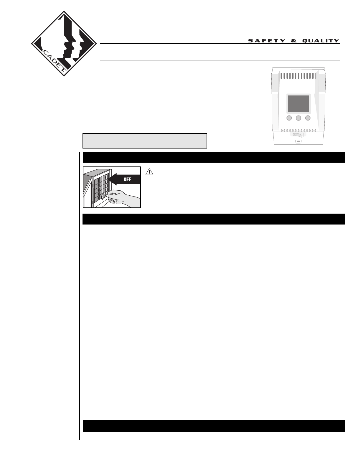
WARNING
Turn the electrical power off at the electrical panel
board (circuit breaker or fuse box) and lock or tag the
panel board door to prevent someone from turning on
power while you are working on the heater. Failure to
do so could result in serious electrical shock, burns,
or possible death.
©2005 Cadet Manufacturing Co. Printed in U.S.A. 12/05 #720004
Page 2
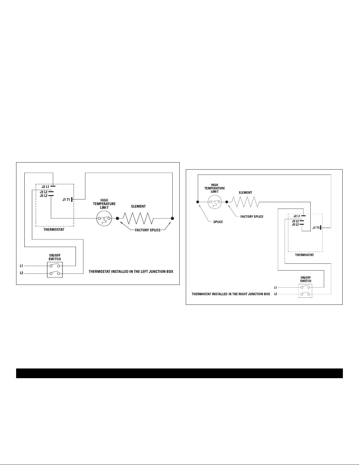
Baseboard/Thermostat Wiring
Thermostat in left junction box: (Figure A)
1. Locate and cut closed end splice of wires containing limit lead wire
and return wire (wire behind deflector). Strip 1/2" of insulation from
these two cut lead wires.
a. Join the lead wire from the limit with the lead wire from
thermostat terminal J5L2 with a connector.
b. Join the return wire (wire behind deflector) with the lead
wire from thermostat terminal J1T1 with a connector.
2. Connect the grounding lead of the power supply to the supplied
grounding pigtail (copper wire attached to case in junction box) with a
connector.
3. Connect each of the remaining two power supply leads to each lead
from the thermostat rocker switch with a wire connector.
a. Be sure the panel does not interfere with the mounting of
the thermostat plate. Move panel if needed. (Using a rubbercoated tool, or hammer handle; carefully pry upwards.)
4. Carefully push wiring back into junction box, hook upper edge of faceplate under lip of case. Lower bottom edge of faceplate to junction
box surface and secure thermostat with mounting screw.
5. Rocker switch should be placed in the “0” (OFF) position. To finish see
the “Completion of Installation” section below.
Thermostat in right junction box: (Figure B)
1. Cut closed end splice from connection of element lead wire and
return wire (wire behind deflector). Strip 1/2" of insulation from these
two cut lead wires.
a. Join the lead wire from the element with the lead wire
from thermostat terminal J5L2 with a connector.
b. Join the return wire (wire behind deflector) with the lead
wire from thermostat terminal J1T1 with a connector.
2. Connect the grounding lead of the power supply to the supplied
grounding pigtail (copper wire attached to case in junction box) with
a connector.
3. Connect each of the remaining two power supply leads to each lead
from the thermostat rocker switch with a wire connector.
a. Be sure the panel does not interfere with the mounting of
the thermostat plate. Move panel if needed. (Using a rubber-coated tool, or hammer handle; carefully pry
upwards.)
4. Carefully push wiring back into junction box, hook upper edge of
faceplate under lip of case. Lower bottom edge of faceplate to junction box surface and secure thermostat with mounting screw.
5. Rocker switch should be placed in the “0” (OFF) position. To finish see
the “Completion of Installation” section below.
FIGURE “A” (Left Junction Box Wiring)
FIGURE “B” (Right Junction Box Wiring)
Completion of Installation
At this point, the baseboard should be securely mounted, and the SBFT2
thermostat wired and secured to the baseboard junction box. The other
junction box should have the baseboard end plate/cover secured in place.
Verify that the thermostat rocker switch is in the “O” (OFF) position before
reestablishing the electrical power at the panel for power flow to the baseboard heater.
Refer to the programming guide for the operation of the SBFT2 thermostat.
Warranty
LIMITED ONE-YEAR WARRANTY: Cadet Manufacturing Co. will repair or replace
any Cadet product, including thermostats, found to be defective or malfunctioning from first date of purchase through the first year.
These warranties do not apply:
1. To conditions resulting from improper installation or incorrect supply voltage;
2. To conditions resulting from improper maintenance, misuse, abuse, accident, or
alteration;
3. To service calls, or any warranty labor not performed at the Cadet Manufacturing facility;
4. If the date of manufacture cannot be determined;
5. To freight damaged products.
CADET SHALL NOT BE LIABLE FOR DAMAGES SUCH AS PROPERTY DAMAGE
AND/OR INCIDENTAL EXPENSES RESULTING FROM BREACH OF THESE WRITTEN WARRANTIES OR ANY IMPLIED WARRANTY.
These warranties give you specific legal rights, and you may also have other rights
which vary from state to state. Cadet neither assumes, nor authorizes anyone to
assume for it, any other obligation or liability in connection with these electric
heaters or any part of such heaters.
If the product should become defective during the warranty period, contact Cadet
Manufacturing Co. at 360-693-2505 for instructions on how to have the repair or
replacement processed. Products returned without authorization will be refused.
Parts and Service
Contact Cadet for information on Parts or Service.
Page 3

INFORMACIÓN IMPORTANTE
CONSERVE ESTAS INSTRUCCIONES
Instrucciones para la Instalación
Herramientas necesarias: Destornillador Phillips, conectores de
alambre aislados (WireNuts®), pelacables, cortadores de alambre
TEL: 360-693-2505 Fax: 360-694-8668 P.O. Box 1675 Vancouver, WA 98668-1675
LEA COMPLETAMENTE ESTAS INSTRUCCIONES ANTES
DE PROCEDER CON LA INSTALACIÓN DEL TERMOSTATO
"SBFT2" EN UN ZÓCALO CADET SERIE "F"
Para todas las aplicaciones
Se debe montar el termostato en la misma caja de empalmes
(compartimiento de cables) que la fuente de alimentación eléctrica. Si el conductor de puesta a tierra del chasis suministrado
no está en la caja de empalmes se deberá reubicar en el
extremo cableado.
Puede que la instalación del termostato SMART-BASE requiera
un ligero ajuste del panel en la parte delantera del calentador,
para que el termostato quepa libremente en la caja de
empalmes. Para ello, retire ambas cubiertas de la caja de
empalmes y destrabe la parte inferior del panel de sus colgadores. (Utilice una herramienta (o el mango de un martillo)
revestido con caucho para retirar el panel. Haga palanca cuidadosamente hacia arriba para retirarlo.) Luego deslícelo hacia
atrás de la abertura de la caja de empalmes que se usará para
el termostato hasta que el borde quede apenas colgando sobre
la separación. Sostenga el panel y encájelo nuevamente en
sus colgadores. El termostato ahora tendrá espacio suficiente
para caber en la abertura de la caja de empalmes.
Reemplazo del control del termostato
BTF existente
SBFT2
Instrucciones de instalación del
termostato SMART-BASE
1. Retire el tornillo que sujeta el conjunto del BTF existente (termostato y placa) con el chasis del zócalo y tire de él cuidadosamente para dejar a la vista el cableado y las conexiones. (Con un medidor o probador de circuitos, verifique que
no haya alimentación eléctrica antes de proceder.)
2. Si se ha instalado la fuente de alimentación del zócalo en
esta caja de empalmes, deshaga las conexiones de cableado
y quite el conjunto del termostato antiguo. Siga el diagrama
de cableado correspondiente ("FIGURA A" para el accesorio
del extremo izquierdo, "FIGURA B" para el del extremo derecho) y las siguientes instrucciones para el "Cableado del
zócalo/termostato" a fin de conectar el SBFT2 al zócalo y la
fuente de alimentación.
3. Si la fuente de alimentación no se ha empalmado al zócalo
en esta caja de empalmes, quite el conjunto del termostato
antiguo retirando las conexiones de cableado. El nuevo termostato (SBFT2) se debe colocar en la misma caja de
empalmes de la fuente eléctrica suministrada; por lo tanto,
pele 1/2" de aislamiento de los dos conductores sueltos (que
quedaron al momento de haber retirado el termostato) y
vuelva a unir los dos alambres mediante un conector.
Retire la placa extrema de la otra caja de empalmes y
aplíquela a la caja de empalmes donde se retiró el termostato. Siga el diagrama de cableado correcto ("FIGURA A" para
el accesorio del extremo izquierdo, "FIGURA B" para el del
derecho) y las siguientes instrucciones de "Cableado del
zócalo/termostato" a fin de conectar el SBFT2 al zócalo y la
fuente de alimentación.
Como parte de una instalación nueva
Instale el calentador de zócalo Cadet serie "F" según las
instrucciones de instalación que vienen con el producto.
Recuerde que el termostato SBFT2 se debe instalar en la misma
caja de empalmes (compartimiento de cables) que la fuente
eléctrica suministrada. Si el conductor de tierra del chasis suministrado no está en esta caja de empalmes, se deberá reubicar
en el extremo cableado.
¡IMPORTANTE!
Es extremadamente
importante verificar
que la ali-
mentación eléctri-
ca que recibirá el
calentador tenga el
voltaje correcto.
Conectar un calen-
tador con un sum-
inistro de voltaje
inferior al que cor-
responde reducirá
la potencia, y
conectarlo a un
voltaje superior
puede causar
daños materiales y
lesiones person-
ales. El termostato
electrónico sólo
funcionará correc-
tamente con cir-
cuitos de 240 y 208
voltios.
TM
ADVERTENCIA
Desconecte la electricidad en el tablero del panel eléctrico (caja de
cortacircuitos o fusibles) y trabe o coloque un cartel en la puerta del
tablero del panel para evitar que alguien vuelva a conectar la
energía mientras se esté trabajando en el calentador. De lo contrario
podrían producirse graves golpes eléctricos, quemaduras e incluso
la muerte.
©2005 Cadet Manufacturing Co. Printed in U.S.A. 12/05 #720004
Page 4

Cableado del zócalo/termostato
Termostato en la caja de empalmes izquierda: (Figura A)
1. Localice y corte el empalme de extremo cerrado de los alambres que contiene el alambre conductor de límite y el de retorno (situado detrás del
deflector). Pele 1/2" de aislamiento de estos dos alambres conductores cortados.
a. Una el alambre conductor del interruptor de límite y el alambre
conductor del terminal J5L2 del termostato mediante un conector.
b. Una el alambre de retorno (situado detrás del deflector) con el
alambre conductor del terminal J1T1 del termostato mediante un
conector.
2. Conecte el conductor de tierra de la fuente de alimentación al cable espiral
de puesta a tierra suministrado (alambre de cobre empalmado al chasis en
la caja de empalmes) mediante un conector.
3. Conecte los dos conductores restantes del suministro de alimentación a
cada conductor del interruptor basculante del termostato mediante un
conector de alambres.
a. Cerciórese de que el panel no interfiera con la montura de la
placa del termostato. Mueva el panel si es necesario. (Utilice una
herramienta (o el mango de un martillo) revestido con caucho
para hacer palanca cuidadosamente hacia afuera.)
4. Presione cuidadosamente el cableado para volver a introducirlo en la caja
de empalmes, enganche el borde superior de la placa delantera bajo el
reborde del chasis. Baje el borde inferior de la placa delantera a la superficie de la caja de empalmes y fije el termostato con el tornillo de montaje.
5. El interruptor basculante se debe poner en la posición de apagado "0" (OFF).
Para terminar, consulte la sección "Completar la instalación" a continuación.
El termostato en la caja de empalmes derecha: (Figura B)
1. Corte el empalme de extremo cerrado proveniente de la conexión del
alambre conductor del elemento y el alambre de retorno (situado detrás
del deflector). Pele 1/2" de aislamiento de estos dos alambres conductores cortados.
a. Una el alambre conductor del elemento con el alambre con
ductor del terminal J5L2 del termostato mediante un conector.
b. Una el alambre de retorno (situado detrás del deflector) con el
alambre conductor del terminal J1T1 del termostato mediante
un conector.
2. Conecte el conductor de puesta a tierra de la fuente de alimentación al
cable espiral de puesta a tierra suministrado (alambre de cobre empalmado al chasis en la caja de empalmes) mediante un conector.
3. Conecte los dos conductores restantes del suministro de alimentación a
cada conductor del interruptor basculante del termostato mediante un
conector de alambres.
a. Cerciórese de que el panel no interfiera con la montura de la
placa del termostato. Mueva el panel si es necesario. (Utilice
una herramienta (o el mango de un martillo) revestido con
caucho para hacer palanca cuidadosamente hacia afuera.)
4. Presione cuidadosamente el cableado para volver a introducirlo en la
caja de empalmes, enganche el borde superior de la placa delantera bajo
el reborde del chasis. Baje el borde inferior de la placa delantera a la
superficie de la caja de empalmes y fije el termostato con el tornillo de
montaje.
5. El interruptor basculante se debe poner en la posición de apagado "0"
(OFF). Para terminar, consulte la sección "Completar la instalación" a continuación.
Elemento
Empalme
de fábrica
Interruptor límite
de alta
temperatura
Termostato instalado en la caja
de empalmes izquierda
Interruptor de
encendido/apagado
Termostato
Interruptor límite
de alta
temperatura
Elemento
Empalme
de fábrica
Termostato
Interruptor de
encendido/apagado
Termostato instalado en la caja
de empalmes derecha
Empalme
FIGURA "A" (cableado de la caja de empalmes izquierda)
FIGURA "B" (cableado de la caja de empalmes derecha)
Completar la instalación
En este momento, se debe montar firmemente el zócalo, y cablear y afianzar
el termostato SBFT2 a la caja de empalmes del zócalo. También se debe
asegurar bien la caja de empalmes en la placa extrema/cubierta del zócalo.
Verifique que el interruptor basculante del termostato esté en la posición "O"
(OFF) antes de restablecer la alimentación eléctrica en el panel para el flujo
de alimentación hacia el calentador de zócalo.
Consulte la guía de programación para la operación del termostato SBFT2.
GARANTIA LIMITADA DE UN AÑO: Cadet Manufacturing Co. reparará o reem-
plazará cualquier producto Cadet, incluyendo termostatos que se determine es
defectuoso o está funcionando mal desde la fecha de compra original hasta el
primer año.
ESTAS GARANTíAS NO SON PERTINENTES:
1) Para condiciones que sean el resultado de la instalación inapropiada o del
suministro incorrecto de voltaje;
2) Para condiciones que sean el resultado del mantenimiento inapropiado, mal
uso, abuso, accidente o alteración
3) Para las llamadas de servicio o mano de obra que involucren el cambio de
pieza(s) defectuosa(s)
4) Si no se puede determinar la fecha de fabricación
5) Para los productos dañados durante el flete.
CADET NO SERÁ RESPONSABLE DE LOS DAÑOS A LA PROPIEDAD Y/O GASTOS INCIDENTALES QUE RESULTEN DEL INCUMPLIMIENTO DE ESTAS GARANTÍAS ESCRITAS
O DE CUALQUIER GARANTIA IMPLICITA.
Estas garantías le otorgan derechos legales específicos y es posible que usted cuente
con otros derechos que varían de acuerdo a cada estado.
Cadet no asume ni autoriza a nadie para que asuma de su parte ninguna otra
obligación o responsabilidad contra terceros relacionada con estos calentadores eléctricos o con cualquier parte de dichos calentadores.
Si el producto llegara a ser defectuoso durante el período de garantía, comunicarse con
Cadet Manufacturing llamando al 360-693-2505 para obtener instrucciones acerca de
como procesar la reparación o reemplazo. Los productos que se devuelvan sin autorización serán rechazados.
Repuestos y servicio
Comuníquese con Cadet para obtener información sobre repuestos o servicio.
Page 5

General Programming Operation:
5-1-1 programming allows you to create a heating schedule that is specific to
your needs: weekdays, Saturday, and Sunday. Weekdays are a single unit,
meaning the program schedule will be the same for Monday, Tuesday,
Wednesday, Thursday, and Friday. Saturday and Sunday can each have
individual programs. Every weekday, Saturday, or Sunday program has 4 daily
settings: WAKE, LEAVE, RETURN, and SLEEP.
✦ WAKE: The desired room temperature and time the heating period should
begin when you are present in the morning. If desired, allow 15 minutes
prior to wake time for the room to reach comfort level.
✦ LEAVE: The time and the lower desired temperature you would like your
room to be when you leave for the day. This is an energy saving period.
✦ RETURN: The desired room temperature and time the heating period
should begin when you are present in the evening. If desired, allow 15
minutes prior to your return time for the room to reach comfort level.
✦ SLEEP: The time and the lower desired temperature you would like your
room to be while you sleep. This is an energy saving period.
Each setting needs to be programmed with a time and temperature.
Programming begins by directing you to set the time of day for the 4 daily
settings for weekdays, Saturday, and Sunday. Once all times have been set, the
program will direct you to set the temperatures for the 4 daily settings for
weekdays, Saturday, and Sunday.
Operation Modes:
✦ The AUTOmatic mode runs the programmed sequence recorded by the
user. Use this mode when daily comfort needs and routine are in
accordance with the recorded program.
✦ The MANUAL mode overrides the recorded program sequence. Use this
mode when out of town or when maintaining a certain temperature set
point for an extended period of time is desired. Setting the manual
temperature to a cool set point of 62 degrees or less helps reduce energy costs. The MANUAL mode stays active until the AUTOmatic program
is activated.
✦ The Temporary Setpoint overrides the programmed temperature when
AUTO mode is activated. Set a Temporary Setpoint when changing the
temperature for a given period of the day. The setpoint will stay active until
the next programmed period for the given day.
Energy Saving Tips:
Here are a few tips to maximize energy saving capabilities:
✦ When programming, always set the temperature back for a minimum of 8
hours when away from home or asleep.
✦ Each 2-degree decrease for an 8 hour period is equivalent to a 2% savings.
✦ Maximize the 8 hour temperature set back by reducing the setpoint 8 to
10 degrees from your preferred comfort setpoint.
✦ Use the manual mode to set and hold the temperature back 8 degrees or
more while on vacation.
✦ Or, maintain default program. The thermostat comes equipped with
an energy saving program, as outlined in the “Default Settings” table.
1. To activate the PROGRAM MODE,
press the MODE button. CLOCK,
NEXT, SCHED appear on the display.
3. To set the hours, press the down
▼
button to decrease the hour or the
up
▲
button to advance. Note: the
clock is a 24 hour clock and will display
AM or PM to distinguish time of day.
The AM/PM icon will change with
setting the hours.
5. Press the MODE button to activate
the set day of week mode. The SU icon
will flash. To set the day, press the
down
▼
button to select the previous
day or the up
▲
button to select the
next day. Only the selected day will
show on the LCD. Press the MODE
button to save your selection.
2. To activate the CLOCK MODE,
press the DOWN
▼
button. The hour
numerals will flash.
4. Press the MODE button to activate
the set minutes mode. The minute
numerals will flash. To set the minutes,
press the down
▼
button to decrease the
minutes or the up
▲
button to advance.
PROGRAMMING THE
AUTO SCHEDULE
1.To activate the PROGRAM MODE,
press the MODE button once. CLOCK,
NEXT, SCHED appear on the display.
3. To program the WAKE time setting,
press the down
▼
button to decrease
the time or the up
▲
button to increase.
When the time setting is correct, press
the MODE button to advance to
program the LEAVE time setting.
5. To program the RETURN time
setting, press the down
▼
button to
decrease the time or the up
▲
button
to increase. When the time setting is
correct, press the MODE button to
program the SLEEP time setting.
7. To program the WAKE, LEAVE,
RETURN and SLEEP time settings for
both Saturday (SA) and Sunday (SU),
return to the beginning of the
PROGRAMMING AUTO SCHEDULE
instructions and repeat.
2. To activate the AUTO SCHEDULE
program mode, press the up
▲
button
once. The first display will be the WAKE
time for Monday through Friday. Time
adjustments are made in 15 minute
increments.
4. To program the LEAVE time setting,
press the down
▼
button to decrease
the time or the up
▲
button to increase.
When the time setting is correct, press
the MODE button to advance to
program the RETURN time setting.
6. To program the SLEEP time setting,
press the down
▼
button to decrease
the time or the up
▲
button to increase.
When the time setting is correct, press
the MODE button to program the
Saturday WAKE time setting.
8. After programming the Saturday and
Sunday time settings, press the MODE
button to program the Monday through
Friday WAKE setpoint temperature. To
program setpoint temps, press the
down
▼
button to decrease the temp
or the up
▲
button to increase. When
the temperature setting is correct,
press the MODE button to advance to
program the LEAVE temp.
9. Continue to program the setpoint
temperatures by pressing the MODE
button to advance to LEAVE, RETURN
and then SLEEP. For each schedule,
press either the down
▼
button or the up
▲
button to program the correct setpoint.
Press the MODE button to advance.
AUTO and MANUAL Modes:
Selecting AUTO or MANUAL
MODE:
1. To select the AUTO or MANUAL
operating mode, press the MODE button
twice. The MANUAL, RUN, AUTO
appear on the display. The current mode
is identified by a flashing underline. Press
the down
▼
button to select MANUAL
mode or the up
▲
button to select AUTO
mode. To activate the selected operating
mode, press the MODE button again.
Setting a Temporary Setpoint:
3. To set a temporary setpoint
(AUTO mode only), press either the
down
▼
button or the up ▲ button to
display the current setpoint. To change
the setpoint, press the down
▼
button to
decrease the setting or press the up
▲
button to increase. TEMP is displayed to
indicate that a temporary setpoint is
active. The temporary setpoint will be
canceled when the next programmed
operating setting has been activated
(WAKE, LEAVE, RETURN or SLEEP). It
may also be canceled by adjusting the
setpoint up or down until the TEMP icon
disappears.
Before you program your thermostat, take a moment and write a program suitable
to your needs and schedule. You will need to know this before programming the
thermostat. Use the default settings guide above as a guideline.
Programming Instructions:
START UP
How To Press Buttons For Programming:
✦ To change the temperature set point, press the down
▼
or up▲button and hold,
release when desired set point is reached. Temperature increases or decreases
in 1 degree increments.
✦ To change the time of day, press the down
▼
or up▲ button and hold, release
when desired set point is reached. Time of day increases or decreases in 15 minute
increments.
✦ For all other functions, press once to make changes or selections.
Setting the Time of Day and Day of Week:
10. Continue to program the setpoint
temperatures for Saturday and Sunday
by pressing the MODE button to
advance. For each schedule, press
either the down
▼
button or the up
▲
button to program the correct setpoint.
When you have completed the
programming, press the MODE button
to save.
Adjusting MANUAL Setpoint:
2. To adjust the MANUAL mode setpoint,
press either the down
▼
button or the up
▲
button to display the current manual
setpoint. To change the setpoint, press
the down
▼
button to decrease the
setting or press the up
▲
button to
increase. The thermostat will
automatically return to the time/room
temperature display within 30 seconds.
* The SMART-BASE thermostat has been simulated to offer the best performance
for a built-in control. The concept is to simulate a midpoint temperature of the room,
respond to this setting, and maintain it for optimum comfort. However, keep in mind
that temperature variances to this reading could be affected by drafts within the wall
area, cold air from flooring or drafts from a nearby window or door.
©2005 Cadet Manufacturing Co. Printed in U.S.A. 12/05 #720002
The default schedule only applies at the
first start of the microprocessor. When
the thermostat has been programmed,
the default values no longer apply.
Programmed values are retained if the
heater power is interrupted or turned OFF.
Once the power is restored, the thermostat
will be in AUTO mode. However, the clock and
day of the week will require reprogramming.
The thermostat will load its default
program settings when power is
established for the first time. The display
will alternate between a room temperature
display and a time of day display. Both the
time of day and room temperature
displays will continuously flash to indicate
that a power interruption has occured.
* Room
Temperature
Time of Day
Page 6

Operación de programación general:
La programación 5-1-1 permite crear un programa de calefacción específico
para sus necesidades: días hábiles, sábado y domingo. Los días hábiles constituyen una sola unidad, lo cual significa que el horario de la programación será
igual para el lunes, martes, miércoles, jueves y viernes. El sábado y el domingo
pueden tener programas individuales. Cada programa para días hábiles, sábado o domingo tiene cuatro ajustes diarios: DESPERTAR, SALIDA, REGRESO y
NOCHE.
✦ DESPERTAR: La temperatura ambiental y la hora en que desee que
comience el período de calefacción cuando usted esté presente en la
mañana. Si lo desea, fíjelo 15 minutos antes de la hora en que despierte
para que la habitación alcance el nivel de su comodidad.
✦ SALIDA: La hora y la temperatura más baja en la que desee que quede la
habitación cuando salga durante el día. Éste es un período de ahorro de energía.
✦ REGRESO: La temperatura ambiental y la hora en que desee que
comience el período de calefacción cuando usted regrese a su hogar. Si lo
desea, fíjelo 15 minutos antes de la hora en que regrese para que la
habitación alcance el nivel de su comodidad.
✦ NOCHE: La hora y la temperatura menor que desee para la habitación
mientras usted duerme. Éste es un período de ahorro de energía.
Cada ajuste se debe programar con una hora y temperatura. Para comenzar la programación deberá fijar la hora del día para los 4 ajustes diarios de los días hábiles y del sábado y domingo. Una vez que se han fijado todas las horas, el programa le indicará que fije
las temperaturas para los 4 ajustes diarios de los días hábiles y del sábado y domingo.
Modos de operación:
✦ El modo AUTOmático funciona con la secuencia programada que grabó el
usuario. Utilice este modo cuando sus necesidades diarias de comodidad
y su rutina concuerden con el programa grabado.
✦ El modo MANUAL supedita la secuencia de programación grabada. Utilice este modo
cuando esté fuera de la ciudad o cuando quiera mantener una determinada temperatura durante un período prolongado. Fijar la temperatura manual en un punto de
ajuste fresco de 62 grados o menos ayuda a reducir los costos de energía. El modo
MANUAL se mantiene vigente hasta que se activa el programa AUTOmático.
✦ El punto de fijación temporal supedita la temperatura programada cuando
se activa el modo AUTO. Fije un punto de ajuste temporal al cambiar la
temperatura durante un período determinado del día. El punto de ajuste se
mantendrá activo hasta el siguiente período programado del día determinado.
Consejos para ahorrar energía:
He aquí algunos consejos para maximizar el ahorro de energía:
✦ Programe una temperatura menor durante un mínimo de 8 horas cuando
no se encuentre su hogar o bien cuando esté durmiendo.
✦ Cada disminución de 2 grados durante un período de 8 horas equivale a un
ahorro del 2%.
✦ Aproveche al máximo el período de ahorro de 8 horas fijando su punto de
ajuste en 8 a 10 grados menos que la temperatura que prefiere.
✦ Utilice el modo manual para fijar y conservar la temperatura en un mínimo
de 8 grados menos cuando esté de vacaciones.
✦ O bien, mantenga el programa predeterminado. El termostato viene
equipado con un programa de ahorro de energía, tal como se describe
en la tabla "Ajustes predeterminados".
1. Para activar el modo de progra-
mación (PROGRAM MODE), pulse el
botón Modo (MODE). Aparecerá
CLOCK, NEXT, SCHED (Reloj,
Siguiente, Progr.) en pantalla.
3. Para fijar las horas, pulse el botón
descendente
▼
a fin de bajar la hora o
el ascendente
▲
para subirla. Nota: el
reloj tiene 24 horas y mostrará los indicadores AM o PM para distinguir entre la
mañana y la tarde. El icono AM/PM cambiará a medida que se ajusten las horas.
5. Pulse el botón Modo (MODE) para activar el modo de fijación de día hábil. El
icono SU destellará. Para fijar el día, pulse
el botón descendente
▼
a fin de seleccionar el día anterior o el botón ascendente
▲
para seleccionar el día siguiente.
Sólo aparecerá el día seleccionado en la
pantalla LCD. Pulse el botón Modo
(MODE) para guardar su selección.
2. Para activar el modo de reloj (CLOCK
MODE), pulse el botón descendente
▼
Los dígitos de hora destellarán.
4. Pulse el botón Modo (MODE) para
activar el modo de fijación de minutos.
Los dígitos de los minutos destellarán.
Para fijar los minutos, pulse el botón
descendente
▼
para bajar los minutos o
el ascendente
▲
para subirlos.
PROGRAMAR EL
HORARIO AUTOMÁTICO
1.Para activar el modo de progra-
mación (PROGRAM MODE), pulse el
botón Modo (MODE) una vez.
Aparecerá CLOCK, NEXT, SCHED
(Reloj, Siguiente, Progr.) en pantalla.
3. Para programar el ajuste de la hora
de despertar (WAKE), pulse el botón
descendente
▼
para bajar la hora o el
botón ascendente
▲
para subirla.
Cuando el ajuste de la hora sea el correcto, pulse el botón Modo (MODE)
para avanzar y programar la hora de
salida (LEAVE).
5. Para programar el ajuste de la hora de
regreso (RETURN), pulse el botón
descendente
▼
para bajar la hora o el
botón ascendente
▲
para subirla.
Cuando el ajuste de la hora sea el correcto, pulse el botón Modo (MODE) para
programar el ajuste nocturno (SLEEP).
7. Para programar los ajustes de hora
de despertar, salida, regreso y nocturna (WAKE, LEAVE, RETURN y
SLEEP) tanto para el sábado como
para el domingo (SA y SU respectivamente), vuelva al comienzo de las
instrucciones de la sección PROGRAMAR EL HORARIO AUTOMÁTICO y
repita los pasos.
2. Para activar el modo de programación
Horario automático (AUTO SCHEDULE),
pulse el botón ascendente
▲
una vez. La
primera pantalla corresponderá a la hora
de despertar (WAKE) para los días
hábiles. Los ajustes de hora se realizan
en incrementos de 15 minutos.
4. Para programar el ajuste de la hora de
salida (LEAVE), pulse el botón descendente
▼
para bajar la hora o el botón ascen-
dente
▲
para subirla. Cuando el ajuste de
la hora sea el correcto, pulse el botón
Modo (MODE) para avanzar a la programación de la hora de regreso (RETURN).
6. Para programar el ajuste nocturno
(SLEEP), pulse el botón descendente
▼
para bajar la hora o el botón ascendente
▲
para subirla. Cuando el ajuste de la
hora sea el correcto, pulse el botón Modo
(MODE) para programar el ajuste de la
hora de despertar (WAKE) del sábado.
8. Después de programar los ajustes de
horas del sábado y el domingo, pulse el
botón Modo (MODE) con el objeto de programar la temperatura para despertar
(WAKE) de los días hábiles. Para programar las temperaturas, pulse el botón
descendente
▼
para bajar la temperatura
o el botón ascendente
▲
para subirla.
Cuando el ajuste de la temperatura sea el
correcto, pulse el botón Modo (MODE)
para avanzar a la programación de la
temperatura de salida (LEAVE).
9. Continúe programando las temperaturas pulsando el botón Modo (MODE)
para avanzar por las modalidades de
salida (LEAVE), regreso (RETURN) y
luego nocturna (SLEEP). En cada programa, pulse ya sea el botón descendente
▼
o el ascendente ▲para programar el punto de ajuste correcto. Pulse el
botón Modo (MODE) para avanzar.
Modos AUTO y MANUAL:
Seleccionar el modo AUTO o
el MANUAL:
1. Para seleccionar el modo de
operación AUTO o MANUAL, pulse el
botón Modo (MODE) dos veces.
Aparecerá MANUAL, RUN, AUTO
(Manual, Funcionar, Auto) en pantalla. El
modo actual se identifica mediante un
subrayado parpadeante. Pulse el botón
descendente
▼
para seleccionar el
modo MANUAL o el botón ascendente
▲
para seleccionar el modo AUTO.
Para activar el modo de operación seleccionado, pulse el botón Modo (MODE)
nuevamente.
Fijar un punto de ajuste temporal:
3. Para fijar un punto de ajuste temporal
(sólo en el modo AUTO), pulse ya sea el
botón descendente
▼
o el ascendente
▲
para mostrar el punto de ajuste actual. Para cambiar el punto de fijación,
pulse el botón descendente
▼
para
bajar el ajuste o el botón ascendente
▲
para subirlo. Aparece TEMP en la pantalla para indicar que se ha activado un
punto de ajuste temporal. El punto de
ajuste temporal se cancelará cuando se
haya activado el siguiente ajuste de
operación programado (despertar
[WAKE], salida [LEAVE], regreso
[RETURN] o noche [SLEEP]). También
se puede cancelar subiendo o bajando
el punto de ajuste hasta que aparezca el
icono TEMP.
Antes de programar el termostato, dedique un momento a escribir un programa adecuado para sus necesidades y horarios. Deberá tener esta información antes de programar el termostato. Utilice los ajustes predeterminados descritos anteriormente
como pauta general.
Instrucciones de programación:
INICIO
Cómo Presionar Los Botones Para Programar:
✦ Para cambiar la temperatura, pulse ininterrumpidamente el botón descendente
▼
o ascendente▲hasta llegar al valor que desea, y luego suéltelo. La temperatura
aumenta o disminuye en incrementos de 1 grado.
✦ Para cambiar la hora del día, pulse ininterrumpidamente el botón descendente
▼
o
ascendente
▲
hasta llegar al valor que desea, y luego suéltelo. La hora del día
aumenta o disminuye en incrementos de 15 minutos.
✦ Para todas las demás funciones, vaya pulsando de una sola vez a fin de realizar cam-
bios o selecciones.
Fijar la hora del día y el día hábil:
10. Continúe programando las temperat-
uras para el sábado y el domingo pulsando el botón Modo (MODE) para
avanzar. En cada programa, pulse ya
sea el botón descendente
▼
o el ascen-
dente
▲
para programar el punto de
ajuste correcto. Cuando haya completado la programación, pulse el botón Modo
(MODE) para guardar.
Ajustar el punto de fijación
MANUAL:
2. Para ajustar el punto de fijación del
modo MANUAL, pulse ya sea el botón
descendente
▼
o el botón ascendente
▲
para mostrar el punto de fijación
manual actual. Para cambiar el punto de
fijación, pulse el botón descendente
▼
para bajar el ajuste o el botón ascendente
▲
para subirlo. El termostato
volverá automáticamente a la pantalla
de hora/temperatura ambiente durante
30 segundos.
* La simulación del termostato SMART-BASE ofrece el mejor rendimiento de un
control incorporado. El concepto es simular una temperatura media para el ambiente, responder a este ajuste y mantenerlo para lograr una óptima comodidad. Sin
embargo, no se debe olvidar que las variaciones en la temperatura de las lecturas
podrían verse afectadas por las corrientes de aire dentro de la zona de los muros,
por el aire fresco de los pisos o las corrientes de las ventanas o puertas cercanas.
©2005 Cadet Manufacturing Co. Printed in U.S.A. 12/05 #720002
El programa predeterminado sólo es
válido la primera vez que funciona el
microprocesador. Cuando se ha programado el termostato, los valores predeterminados ya no son válidos.
Los valores programados se conservan si la
energía del calefactor se interrumpe o se
apaga. Una vez que se restablece la
energía, el termostato estará en el modo
AUTO. Sin embargo, el reloj y el día hábil se
deberán reprogramar.
El termostato cargará los ajustes de su programa predeterminado cuando se conecte la
energía por primera vez. El visor alternará
entre la pantalla con la temperatura ambiente y
la pantalla con la hora del día. Tanto la pantalla
de la hora del día como la de la temperatura
destellarán permanentemente para indicar que
se ha producido una interrupción de la energía.
* Temperatura
ambiente
Hora del día
 Loading...