

Cadet RM208, RM202, RM108, RM162, RM151 User Manual
The Register Plus
T
OWNER’S GUIDE
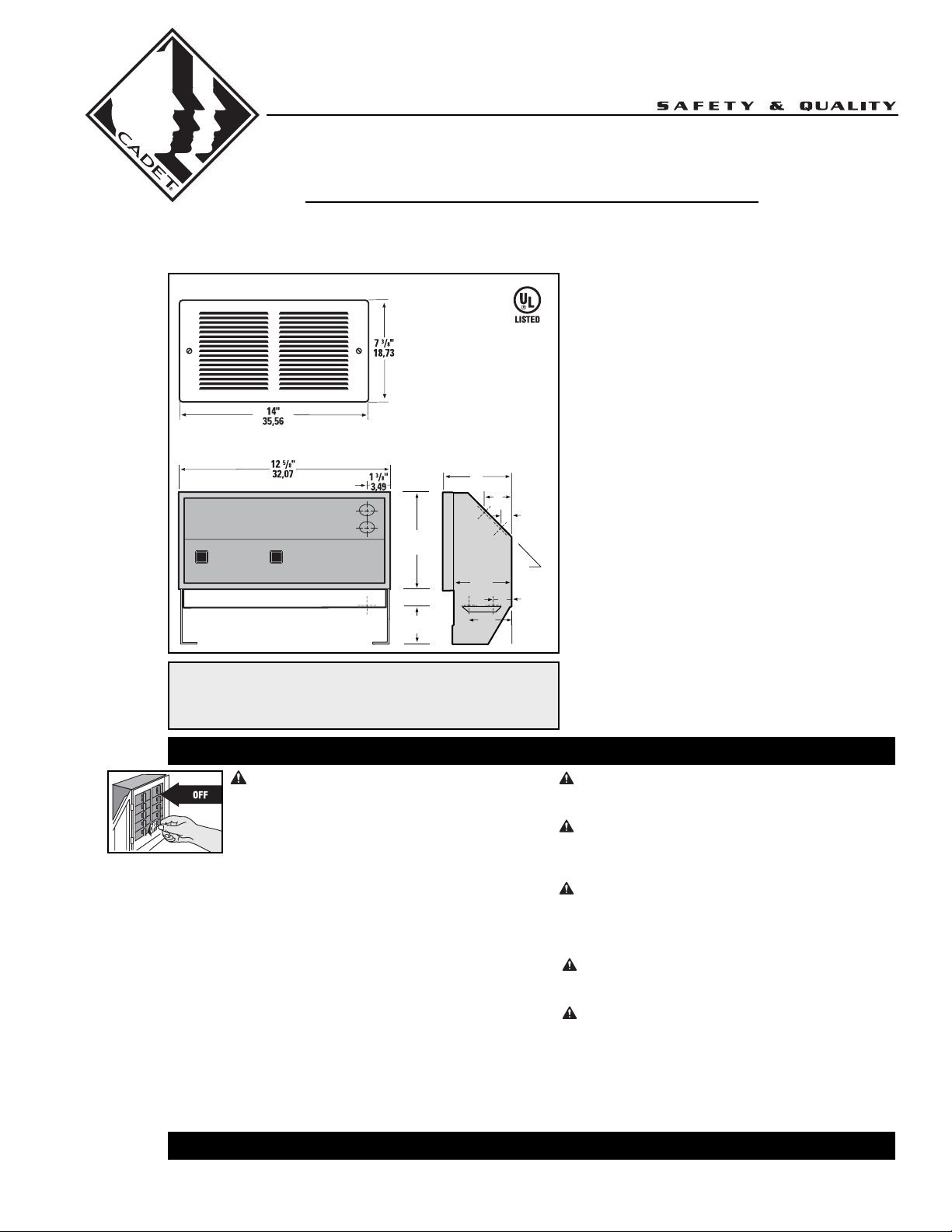
Grill Front
Wall Can Front
Tools Required:
Phillips Screwdriver
Straight Screwdriver
Wire Strippers
Wall Can Side
4"T
10,16
2"T
5,08
5 7/8"T
14,92
3
/8"T
3
Dimensions in
1"T
2,54
2"T
5,08
Utility Knife
(4) 1½“ Wood Screws
(3) Insulated Wire Connectors
(1) Strain Relief Connector
8,57
inches (cm)
1
/2"T
2
6,35
3
1,91
1"T
2,54
/4"T
Features & Benefits
■
Thermal Safeguard:
•
High temperature manual reset:
turns off heater if normal operating
temperatures are exceeded
■
Commercial grade steel element
■
Powder coat paint process eliminates
sharp cutting edges
■
Five year extended warranty
■
Wall can designed for ease of
installation
■
Optional double pole field mount
45˚
thermostat kit available
■
Factory tested
MODELS:
RM202 RM208 RM108
RM151 RM162
Note: Thermostat not included
IMPORTANT INSTRUCTIONS
WARNING
Turn the electrical power off at the electrical
panel board (circuit breaker or fuse box) and lock
or tag the panel board door to prevent someone
from turning on power while you are working on
the heater. Failure to do so could result in serious
electrical shock, burns, or possible death.
1. Read all instructions before using this heater.
2. Read all information labels. Verify that the electrical supply
wires are the same voltage as the heater.
3. All electrical work and materials must comply with the
National Electric Code (NEC), the Occupational Safety and
Health Act (OSHA), and all state and local codes.
4. Connect the grounding pigtail (copper wire) provided in the
wall can to the supply ground wire.
5. If you need to install a new circuit or need additional wiring
information, consult a qualified electrician.
6. Protect electrical supply from kinks, sharp objects, oil,
grease, hot surfaces or chemicals.
TEL: 360-693-2505 Fax: 360-694-8668 P.O. Box 1675 Vancouver, WA 98668-1675
SAVE THESE INSTRUCTIONS
7. WARNING
Overheating or fire may occur. DO NOT install the heater in a
floor, ceiling or behind doors.
8. WARNING
Fire or explosion may occur. DO NOT install heater in any
area where combustible vapors, gases, liquids, or excessive
lint or dust are present.
9. WARNING
Burn Hazard. This heater is hot when in use. To avoid
burns, do not let bare skin touch hot surfaces. Use extreme
caution when any heater is used by or near children or
invalids.
10. WARNING
Risk of Electrical Shock. Connect grounding lead to grounding
wire provided. Keep all foreign objects out of heater.
11. WARNING
Risk of Fire. Do not block heater. Heater must be kept clear of
all obstructions: a minimum of 3 feet in front, 6 inches
above and on both sides. Heaters must be kept clean of lint,
dirt and debris. (See Maintenance Instructions).
12. Use this heater only as described in this manual. Any
other use not recommended by the manufacturer may
cause fire, electrical shock, or injury to persons.
READ ALL
INSTRUCTIONS
AND SAFETY
INFORMATION
Installation Instructions
Part One
PLACEMENT: For best results install The Register Plus on an inside wall. Headers and bracing are not
necessary. NOTE: The wall can must be installed in the TOP UP (horizontal) position only. Heater is not
approved for ceiling mount.
THERMOSTAT: A thermostat is required. A Cadet Elec tronic Thermostat is recommended for ultimate control
and comfort.
IMPORTANT!
It is extremely
important you
verify the
electrical supply
wires are the
same voltage as
the heater (i.e.
120 volt heater to
120 volt power
supply and 240 volt
heater to 240 volt
power supply).
If replacing an
existing heater,
check the labels
of the old heater
and replace using
the same voltage.
Hooking a 240 volt
heater to a 120 volt
power supply will
drastically reduce
the heater's
output. Hooking a
120 volt heater to a
240 volt power
supply will
destroy the heater.
Connecting your
heater to an
incompatible
power supply will
void the warranty.
Warranty is void if
any material is
sprayed on the
element or blower.
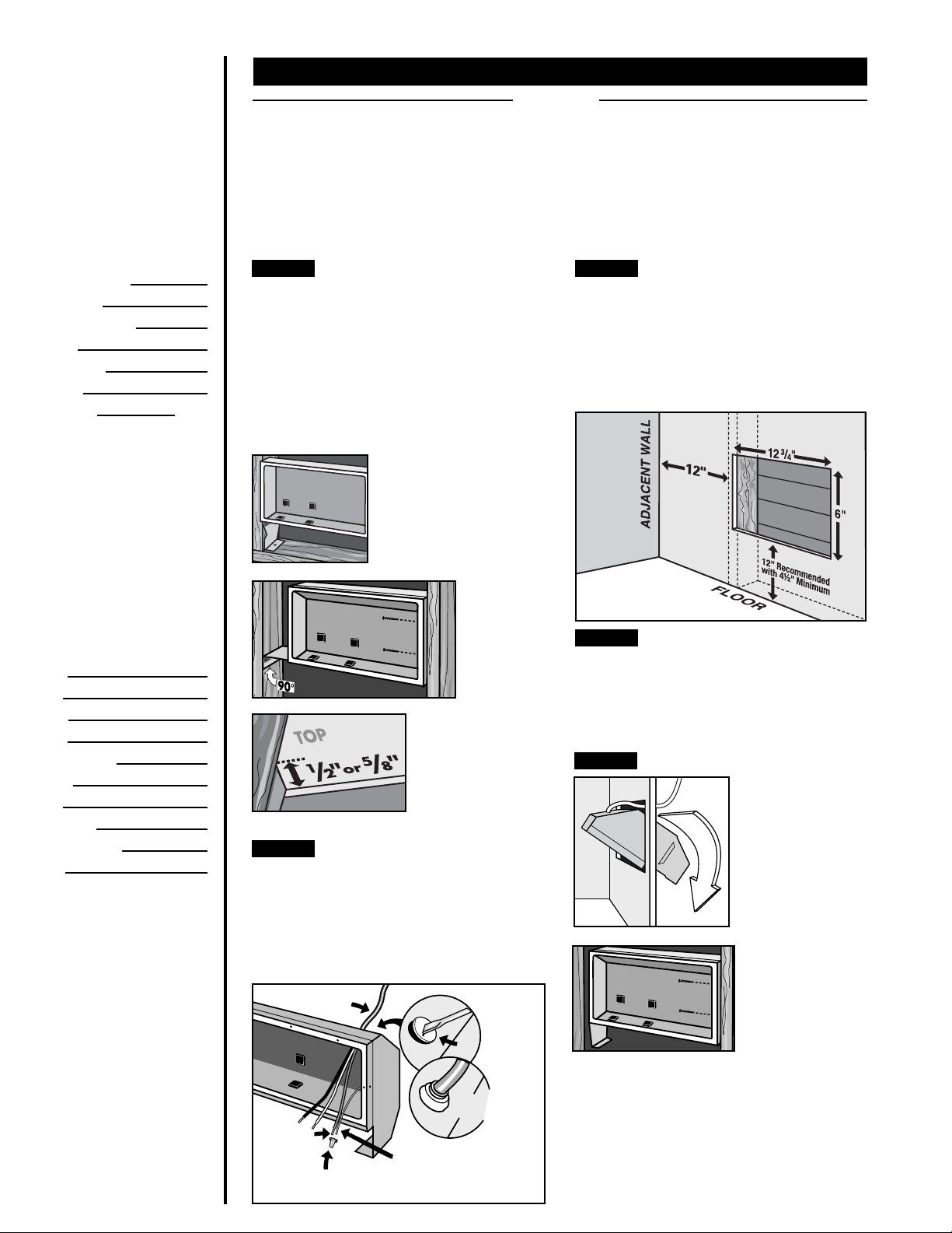
How do I install for new construction?
STEP 1
The RM series REQUIRES A MINIMUM distance
of 6 inches from adjacent surfaces and 4½ inches
from the floor. However, Cadet RECOMMENDS
12 inches from all adjacent surfaces and 12 inches
from the floor (See Figure 5) for longer and cleaner
performance. Heaters must be spaced at least
3 feet apart.
Secure the wall can to the studs and/or sill plate
with screws through the larger (
(See Figures 1 and 2).
STEP 2
Route supply wire from circuit breaker to
thermo stat to wall can. Remove a knockout
and attach the supply wire with a strain relief
connector leaving 10 inches wire lead for later
use. Connect supply ground wire to grounding
pigtail in wall can (See Figure 4). Proceed to
PART TWO.
GROUNDING
Mount Wall Can
FIGURE 1
Metal legs position wall can
at minimum floor clearance.
Route Supply Wires
SUPPLY
WIRE
WIRE
WIRE
CONNECTOR
3
/16 inch) holes.
FIGURE 2
Bend one leg
90 degrees
for higher
placement
and secure
to studs.
FIGURE 3
Face of wall can must
extend ½ inch or
inch from face of stud
to allow for thickness
of sheetrock. Mount
wall can flush with
finished surface.
FIGURE 4
KNOCK-OUT
(TWIST TO
REMOVE)
STRAIN RELIEF
CONNECTOR
GROUNDING
PIGTAIL
5
/8
How do I install in an existing wall?
STEP 1
Cut a hole 12¾ inches wide by 6 inches high
next to wall stud. The RM series REQUIRES A
MINIMUM distance of 6 inches from adjacent
surfaces and 4½ inches from the floor. However,
Cadet RECOMMENDS 12 inches from all adjacent
surfaces and 12 inches from the floor (See
Figure 5) for longer and cleaner performance.
Heaters must be spaced at least 3 feet apart.
FIGURE 5
STEP 2
Route supply wire from circuit breaker to wall
thermo stat, then to wall can. Remove a knockout
and attach the supply wire with a strain relief
connector leaving 10 inches wire lead for later
use (See Figure 4). Connect sup ply ground wire
to ground ing pigtail in wall can.
STEP 3
IMPORTANT: Insert two drywall screws into
the small holes opposite the wall stud into the
drywall to rest against backside of sheetrock
(keeping wall can flush to wall).
Proceed to PART TWO.
Cut Hole In Wall
Route Supply Wires
Mount Wall Can
FIGURE 6
Insert wall can, legs
first, into opening
and rotate into wall.
FIGURE 7
Keeping front of
wall can flush with
finished surface,
secure to wall stud
with screws through
larger (
3
/16 inch) holes.
Installation Instructions
Part Two
STEP 1
below. If you are installing an RM202, RM208, or RM108, begin with STEP 3 below.
STEP 2
Cadet’s Multi-Watt RM heater offers a variety of heat output options. You must first determine the
desired wattage and then configure the heating element wire connections. The heater is shipped from
the factory configured for 1600 Watts (240V) or 1200 Watts (208V) for RM162, and 1500 Watts (120V) for
RM151. If this is the wattage you desire, proceed to STEP 3.
On models RM151 and RM162, mark the wiring diagram on the back of the heater with the wattage used
for future reference.
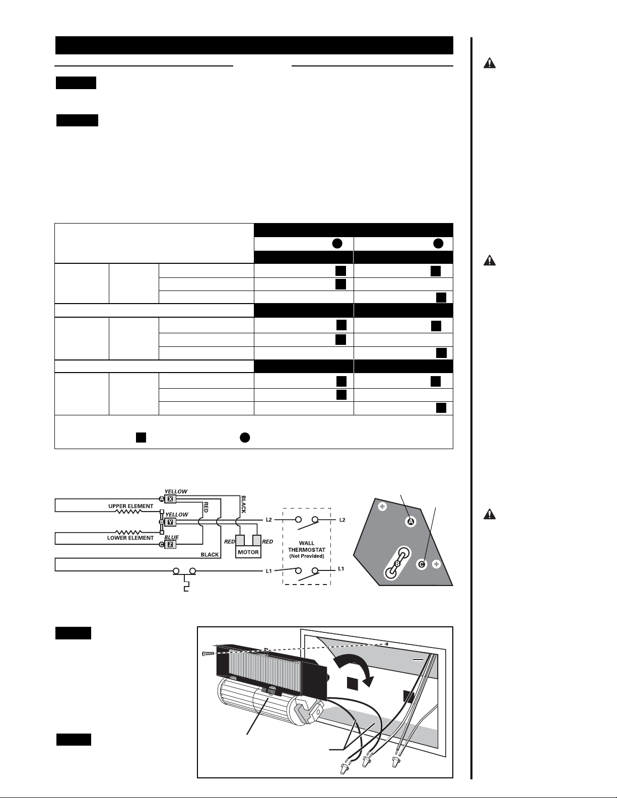
FIGURE 1 RM Wiring Table
*Cut Blue Terminal from Red Wire and wrap with electrical tape.
Yellow Terminal Y remains connected at B . Do Not Touch.
If you are installing a Multi-Watt heater, model numbers RM151 or RM162, begin with STEP 2
Element Wire Configuration (Multi-watt models RM151 or RM162 only)
YOUR WIRES WILL BE CONFIGURED LIKE THIS:
VOLTAGEMODEL
240VRM162
208VRM162
120VRM151
IF YOUR DESIRED
WATTAGE IS:
1600
900
700
1200
675
528
1500
1000
500
Upper Element A
900W-240V
Yellow Terminal X
Yellow Terminal X
None (*)
675W-208V 525W-208V
Yellow Terminal X
Yellow Terminal X
None (*)
1000W-120V
Yellow Terminal X
Yellow Terminal X
None (*)
Lower Element C
700W-240V
Blue Terminal Z
None (*)
Yellow Terminal X
Blue Terminal Z
None (*)
Yellow Terminal X
500W-120V
Blue Terminal Z
None (*)
Yellow Terminal X
WARNING
Risk of Electrical
Shock. Connect
grounding lead to
grounding wire
provided. Keep all
foreign objects out
of heater.
WARNING
Risk of Fire.
Heater must be
kept clear of all
obstructions: a
minimum of 3 feet
in front; 6 inches
on both sides and
above. Heaters
must be kept clean
of lint, dirt and
debris.
STEP 3
Set the heater assembly (blower
wheel first) into the left side of the
wall can. Fasten at top with screw
provided. Unlace heater lead wires.
Connect the supply wires to the
heater wires (See Figure 2). Keep
all wires away from element
connections when wires are pushed
into free space on right of heater.
STEP 4
Secure grill with the screws
provided. Turn power on at the
electrical panel board.
Install Heater Assembly
Install Grill
MANUAL RESET
HIGH TEMP CUTOFF
Manual reset button
Fasten screw
Blower wheel
Heater leads
675W-208V
900W-240V
1000W-120V
Heater Element Locations
Supply leads
525W-208V
700W-240V
500W-120V
Motor End View
FIGURE 2
Grounding
Pigtail
WARNING
Turn the electrical
power off at the
electrical panel
board (circuit
breaker or fuse
box) and lock or
tag the panel board
door to prevent
someone from
turning on power
while you are
working on the
heater. Failure to
do so could result
in serious electrical shock, burns,
or possible death.
 Loading...