

Cadet Perfectoe UC072, Perfectoe UC051, Perfectoe UC101, Perfectoe UC101T, Perfectoe UC102 Owner's Manual

Benets You Can Depend On
3½”
8.89
Grill Front
3½”
8.89
Grill Front
• Slim design with space saving comfort for:
Toekick areas in your kitchen and bath cabinets
Recreational vehicles
Stairwells
Fireplace Hearths
• Safe for you and your family
Peace of mind with automatic high
temperature shutoff feature
• Common sense components designed with you
in mind
1. NO sharp edges
2. Corrosion resistant
3. Rugged, reliable element for instant warmth
4. Easy to install
Perfectoe Heater
Owner’s Manual
http://www.cadetheat.com/wall-heaters/perfectoe
Perfectoe Models
Line
Voltage
240
120
(1)
Standard built-in thermostat is single pole and has no “OFF” position.
(2)
240 volt models can be used at 208 volts. Wattage equals 75% of 240v rated
wattage.
(3)
For installations above 7000 feet, highest wattage recommended is 750 watts.
Note: Optional built-in thermostat kits sold separately
(2)
Model w/o
Thermostat
UC072 750 3.13
UC102
(3)
UC051 500 4.17
UC101
(3)
Model w/
Thermostat
(1)
UC101T
(3)
Watts Amps
1000 4.17
1000 8.33
• Your Cadet heater has been thoroughly tested
and is guaranteed with a 2 year extended
warranty
Wall Can To p
8¼”
21
14½”
36.83
Perfectoe Models With Thermostat
*Wall Thermostat Not Required
Reset Button
Built-in Thermostat
Perfectoe Models Without Thermostat
*Wall Thermostat Required
Rating Label
Grill Side
.375”
.952
Grill Front
18”
45.7
SAVE THESE INSTRUCTIONS
cadetheat.com Tel: 360-693-2505 PO Box 1675 Vancouver, WA 98668-1675
3½”
8.9
Wall Can Side
8¼”
21
TOOLS REQUIRED:
• Phillips Screwdriver
• Straight Screwdriver
• Wire Strippers
• Utility Knife
• (4) 1 1/2“ Wood Screws
• Insulated Wire Connectors
• (1) Strain Relief Connector
Page 1
IMPORTANT INSTRUCTIONS
WARNING
When using electrical appliances, basic precautions should always be followed to reduce the risk of re,
electric shock, and injury to persons, including the following:
1. Read all instructions before installing or using
this heater.
2. WARNING
Risk of Fire. This heater is hot when in use.
Caution—High Temperature. Risk of Fire. Keep
electrical cords, drapery, furnishings, and other
combustibles at least 3 feet from the front of the
heater and 6 inches above and on both sides.
3. WARNING
Burn Hazard. To avoid burns, do not let bare skin
touch hot surfaces. Extreme caution is necessary
when any heater is used by or near children or
invalids and whenever the heater is left operating
and unattended.
4. WARNING
Risk of Electrical Shock. Do not operate any
heater after it malfunctions. Disconnect power
at service panel and have heater inspected by a
qualied electrician before reusing.
5. WARNING
Do not use outdoors.
6. To disconnect heater, turn controls to off, and
turn off power to heater circuit at main disconnect
panel.
7. WARNING
Risk of Electrical Shock. Do not insert or allow
foreign objects to enter any ventilation or exhaust
opening as this may cause an electric shock or
re, or damage the heater.
8. WARNING
Risk of Fire. To prevent a possible re, do not
block air intakes or exhaust in any manner.
9. WARNING
Fire or explosion may occur. A heater has hot and
arcing or sparking parts inside. Do not use it in
areas where gasoline, paint, or ammable vapors
or liquids are used or stored.
10. Use this heater only as described in this
manual. Any other use not recommended by the
manufacturer may cause re, electrical shock, or
injury to persons.
11. The heater must be properly installed before
it is used.
12. WARNING
Risk of Electrical Shock and Fire. Do not operate
without grill.
13. Save these instructions.
SAVE THESE INSTRUCTIONS
Page 2
cadetheat.com Tel: 360-693-2505 PO Box 1675 Vancouver, WA 98668-1675
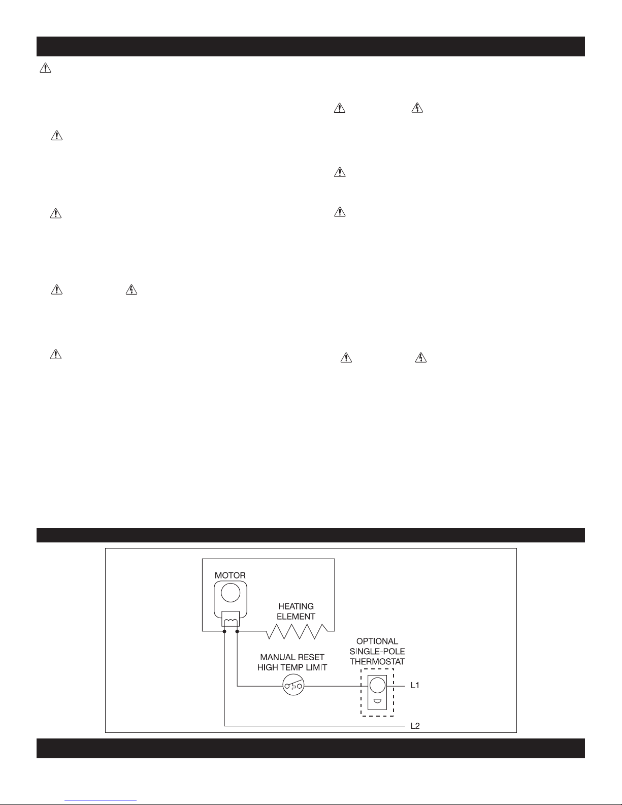
Wiring Diagrams
INSTALLATION INSTRUCTIONS
STRAIN RELIEF
CONNECTOR
GROUNDING
SCREW
1. WARNING
Verify that the electrical supply wires are the same
voltage as the heater.
2. If replacing an existing heater, check the label
of the old heater.
3. All electrical work and materials must comply
with the National Electric Code (NEC), the Occupational Safety and Health Act (OSHA), and all
state and local codes.
4. If you need to install a new circuit or need additional wiring information, consult a qualied electrician.
5. Use copper conductors only.
6. WARNING
Risk of Electrical Shock. DO NOT install the heater directly above bathtub or sink. DO NOT install
in shower stall area (Manufacturer recommends a
minimum 2 foot clearance).
7. Heater must be installed in the wall can
included.
__________________________
PLACEMENT: For best results, install heater beneath a cabinet in the toe kick area. Install the Perfectoe (Model UC)
horizontally. Do not install the UC heater in the oor. Headers and bracing are not necessary. Heater must be installed per
the directions indicated on the lid.
WARNING! Vinyl oor manufacturers warn that some vinyl may discolor from temperatures in excess of 110° F. See your
vinyl oor manufacturer for temperature specications for your vinyl oor covering.
CONTROLS: A thermostat is required. A Cadet electronic thermostat is recommended for ultimate control and comfort.
Optional single or double pole eld mount thermostat kits are also available: Model numbers UCT1 and UCT2.
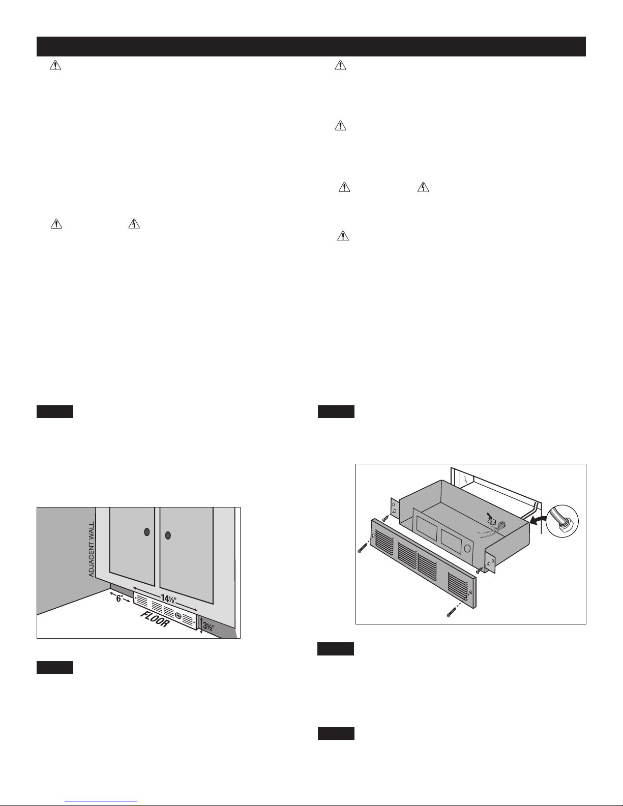
STEP 1
The UC Series heater REQUIRES A MINIMUM distance of 6
inches from adjacent surfaces (see Figure 1). However, Cadet
RECOMMENDS 12 inches from all adjacent surfaces for longer
and cleaner performance. Heaters must be spaced at least 3 feet
apart.
For installation in an existing wall/cabinet, cut a rough opening
14½ inches wide by 3½ inches high. Opening must be 8½ inches
deep.
Determine Area of Installation
Part One
8. WARNING
Risk of Fire. DO NOT install the heater in a oor,
in the ceiling, below a towel bar, behind a door,
or anywhere the air discharge may be blocked in
any manner.
9. WARNING
Fire or Explosion May Occur. A heater has hot
and arcing or sparking parts inside. Do not use it
in areas where gasoline, paint, or ammable vapors or liquids are used or stored.
10. WARNING
Risk of Electrical Shock. Connect grounding lead
to grounding screw provided. Keep all foreign objects out of heater.
11. WARNING
Risk of Fire. This heater is hot when in use.
Caution—High Temperature. Risk of Fire. Keep
electrical cords, drapery, furnishings, and other
combustibles at least 3 feet from the front of the
heater and 6 inches above and on both sides.
__________________________
STEP 3
Connect the supply ground wire to the green grounding screw
provided (See Figure 2). Connect each supply wire to one heater
wire with wire connectors. Note: All wire connections must be
made inside the heater.
Connect Supply Wires
Figure 1
STEP 2
For wall thermostat applications, route supply wire from circuit
breaker to thermostat to rough opening. For models with an
optional eld mount thermostat kit, route supply wire from circuit
breaker to rough opening. Allow enough wire to extend 12 inches
beyond the opening. Place heater lid aside. Remove the knockout
and attach the supply wire with a strain relief connector, leaving 6
inches wire lead for later use (See Figure 2).
Route Supply Wires
Figure 2
STEP 4
Reinstall heater lid and attach using four screws provided. Slide
heater into opening. Fasten heater to cabinet with screws (not
provided) going through the lower holes located on the anges.
Fasten grill to heater with screws provided going through the
upper holes located on the anges.
STEP 5
Turn the electrical power back on at the electrical panel board
(circuit breaker or fuse box).
Mount the Heater
Turn the Electrical Power ON
Page 3
 Loading...