


 Loading...
TRXI-22A, TRXI-24A, TRXI-42A,
AND TRXI-44A ACTIVE
TOKEN RING INTELLIGENT HUB
USER’S GUIDE
CABLETRON SYSTEMS, P. O. Box 5005, Rochester, NH 03867-0505

NOTICE
NOTICE
Cabletron Systems reserves the right to make changes in specifications and other information contained in this document without prior notice. The reader should in all cases consult Cabletron Systems to determine whether any such changes have been made.
The hardware, firmware, or software described in this manual is subject to change without notice.
IN NO EVENT SHALL CABLETRON SYSTEMS BE LIABLE FOR ANY INCIDENTAL, INDIRECT, SPECIAL, OR CONSEQUENTIAL DAMAGES WHATSOEVER (INCLUDING BUT NOT LIMITED TO LOST PROFITS) ARISING OUT OF OR RELATED TO THIS MANUAL OR THE INFORMATION CONTAINED IN IT, EVEN IF CABLETRON SYSTEMS HAS BEEN ADVISED OF, KNOWN, OR SHOULD HAVE KNOWN, THE POSSIBILITY OF SUCH DAMAGES.
© Copyright May 1994 by: Cabletron Systems, Inc.
P.O. Box 5005, Rochester, NH 03867-0505
All Rights Reserved
Printed in the United States of America
Order Number: 9031079 May 94
TRXI-22A, TRXI-24A, TRXI-42A, TRXI-44A, and TPIM are trademarks of Cabletron Systems, Inc.
SPECTRUM, LANVIEW, and Remote LANVIEW are registered trademarks of Cabletron Systems, Inc.
IBM is a registered trademark of International Business Machines Corporation.
DEC, VT200, and VT300 are trademarks of Digital Equipment Corporation.
CompuServe is a trademark of Compuserve, Inc.
Printed On |
Recycled Paper |
i

NOTICE
FCC NOTICE
This device complies with Part 15 of the FCC rules. Operation is subject to the following two conditions: (1) this device may not cause harmful interference, and (2) this device must accept any interference received, including interference that may cause undesired operation.
NOTE: This equipment has been tested and found to comply with the limits for a Class A digital device, pursuant to Part 15 of the FCC rules. These limits are designed to provide reasonable protection against harmful interference when the equipment is operated in a commercial environment. This equipment uses, generates, and can radiate radio frequency energy and if not installed in accordance with the operator’s manual, may cause harmful interference to radio communications. Operation of this equipment in a residential area is likely to cause interference in which case the user will be required to correct the interference at his own expense.
WARNING: Changes or modifications made to this device which are not expressly approved by the party responsible for compliance could void the user’s authority to operate the equipment.
DOC NOTICE
This digital apparatus does not exceed the Class A limits for radio noise emissions from digital apparatus set out in the Radio Interference Regulations of the Canadian Department of Communications.
Le présent appareil numérique n’émet pas de bruits radioélectriques dépassant les limites applicables aux appareils numériques de la class A prescrites dans le Règlement sur le brouillage radioélectrique édicté par le ministère des Communications du Canada.
CABLETRON SYSTEMS, INC. PROGRAM LICENSE AGREEMENT
IMPORTANT: Before utilizing this product, carefully read this License Agreement.
This document is an agreement between you, the end user, and Cabletron Systems, Inc. (“Cabletron”) that sets forth your rights and obligations with respect to the Cabletron software program (the “Program”) contained in this package. The Program may be contained in firmware, chips or other media. BY UTILIZING THE ENCLOSED PRODUCT, YOU ARE AGREEING TO BECOME BOUND BY THE TERMS OF THIS AGREEMENT, WHICH INCLUDES THE LICENSE AND THE LIMITATION OF WARRANTY AND DISCLAIMER OF LIABILITY. IF YOU DO NOT AGREE TO THE TERMS OF THIS AGREEMENT, PROMPTLY RETURN THE UNUSED PRODUCT TO THE PLACE OF PURCHASE FOR A FULL REFUND.
CABLETRON SOFTWARE PROGRAM LICENSE
1.LICENSE. You have the right to use only the one (1) copy of the Program provided in this package subject to the terms and conditions of this License Agreement.
You may not copy, reproduce or transmit any part of the Program except as permitted by the Copyright Act of the United States or as authorized in writing by Cabletron.
ii

NOTICE
2.OTHER RESTRICTIONS. You may not reverse engineer, decompile, or disassemble the Program.
3.APPLICABLE LAW. This License Agreement shall be interpreted and governed under the laws and in the state and federal courts of New Hampshire. You accept the personal jurisdiction and venue of the New Hampshire courts.
EXCLUSION OF WARRANTY AND DISCLAIMER OF LIABILITY
1.EXCLUSION OF WARRANTY. Except as may be specifically provided by Cabletron in writing, Cabletron makes no warranty, expressed or implied, concerning the Program (including Its documentation and media).
CABLETRON DISCLAIMS ALL WARRANTIES, OTHER THAN THOSE SUPPLIED TO YOU BY CABLETRON IN WRITING, EITHER EXPRESS OR IMPLIED, INCLUDING BUT NOT LIMITED TO IMPLIED WARRANTIES OF MERCHANTABLITY AND FITNESS FOR A PARTICULAR PURPOSE, WITH RESPECT TO THE PROGRAM, THE ACCOMPANYING WRITTEN MATERIALS, AND ANY ACCOMPANYING HARDWARE.
2.NO LIABILITY FOR CONSEQUENTIAL DAMAGES. IN NO EVENT SHALL CABLETRON OR ITS SUPPLIERS BE LIABLE FOR ANY DAMAGES WHATSOEVER (INCLUDING, WITHOUT LIMITATION, DAMAGES FOR LOSS OF BUSINESS, PROFITS, BUSINESS INTERRUPTION, LOSS OF BUSINESS INFORMATION, SPECIAL, INCIDENTAL, CONSEQUENTIAL, OR RELIANCE DAMAGES, OR OTHER LOSS) ARISING OUT OF THE USE OR INABILITY TO USE THIS CABLETRON PRODUCT, EVEN IF CABLETRON HAS BEEN ADVISED OF THE POSSIBILITY OF SUCH DAMAGES. BECAUSE SOME STATES DO NOT ALLOW THE EXCLUSION OR LIMITATION OF LIABILITY FOR CONSEQUENTIAL OR INCIDENTAL DAMAGES, OR ON THE DURATION OR LIMITATION OF IMPLIED WARRANTEES IN SOME INSTANCES THE ABOVE LIMITATIONS AND EXCLUSIONS MAY NOT APPLY TO YOU.
UNITED STATES GOVERNMENT RESTRICTED RIGHTS
The enclosed product (a) was developed solely at private expense; (b) contains “restricted computer software” submitted with restricted rights in accordance with Section 5222719 (a) through (d) of the Commercial Computer Software - Restricted Rights Clause and its successors, and (c) in all respects is proprietary data belonging to Cabletron and/or its suppliers.
For Department of Defense units, the product is licensed with “Restricted Rights” as defined in the DoD Supplement to the Federal Acquisition Regulations, Section 52.2277013 (c) (1) (ii) and its successors, and use, duplication, disclosure by the Government is subject to restrictions as set forth in subparagraph (c) (1) (ii) of the Rights in Technical Data and Computer Software clause at 252.227-7013. Cabletron Systems, Inc., 35 Industrial Way. Rochester, New Hampshire 03867
iii

CONTENTS
|
|
TABLE OF CONTENTS |
|
CHAPTER 1 INTRODUCTION |
|
||
1.1 |
USING THIS MANUAL ............................................................ |
1-1 |
|
1.2 |
GETTING HELP........................................................................ |
1-2 |
|
1.3 |
TRXI ACTIVE CONCENTRATOR OVERVIEW...................... |
1-2 |
|
1.4 |
TRXI FEATURES ...................................................................... |
1-3 |
|
1.5 |
REMOTE NETWORK MANAGEMENT CAPABILITIES ...... |
1-6 |
|
1.6 |
RECOMMENDED READING................................................... |
1-6 |
|
CHAPTER 2 REQUIREMENTS/SPECIFICATIONS |
|
||
2.1 |
CABLE SPECIFICATIONS....................................................... |
2-1 |
|
|
2.1.1 UTP Cable Specifications for the TRXI-22A/24A |
|
|
|
|
Lobe Ports and TPIM-T2 .............................................. |
2-2 |
|
2.1.2 STP Cable Specifications For The TRXI-42A/44A |
|
|
|
|
Lobe Ports and TPIM-T1/T4......................................... |
2-4 |
|
2.1.3 |
Mixed Cable Types........................................................ |
2-6 |
|
2.1.4 Multimode Fiber Optic Cable Specifications for |
|
|
|
|
the TPIM-F2 .................................................................. |
2-7 |
|
2.1.5 Single Mode Fiber Optic Cable Specifications for |
|
|
|
|
the TPIM-F3 .................................................................. |
2-8 |
2.2 |
CABLE RECOMMENDATIONS/TROUBLESHOOTING....... |
2-9 |
|
2.3 |
COM 1/COM 2 PORT SPECIFICATIONS.............................. |
2-11 |
|
2.4 |
TPIM SPECIFICATIONS........................................................ |
2-12 |
|
2.5 |
GENERAL SPECIFICATIONS............................................... |
2-17 |
|
CHAPTER 3 INSTALLATION |
|
||
3.1 |
UNPACKING THE TRXI .......................................................... |
3-1 |
|
3.2 |
ATTACHING THE STRAIN RELIEF BRACKET ................... |
3-1 |
|
3.3 |
INSTALLING THE TRXI.......................................................... |
3-2 |
|
|
3.3.1 Rack Mounting the TRXI.............................................. |
3-3 |
|
|
3.3.2 Wall Mounting the TRXI .............................................. |
3-4 |
|
|
3.3.3 |
Free-Standing Installation ........................................... |
3-5 |
3.4 |
SETTING THE RING SPEED SWITCH .................................. |
3-6 |
|
3.5 |
SETTING THE NVRAM SWITCH ........................................... |
3-7 |
|
3.6 |
CONNECTING THE TRXI TO THE POWER SOURCE......... |
3-8 |
|
3.7 |
CONNECTING THE NETWORK LOBE PORT CABLING.... |
3-8 |
|
3.8 |
INSTALLING THE TPIM RI/RO MODULES........................ |
3-11 |
|
v

CONTENTS
3.8.1Setting the TPIM’s Phantom Switch and
RI/RO Switch ............................................................... |
3-12 |
3.8.2 Installing a TPIM to the TRXI.................................... |
3-13 |
3.8.3Connecting a Twisted Pair Segment to
the TPIM-T1 ................................................................ |
3-14 |
3.8.4Connecting a Twisted Pair Segment to
the TPIM-T2 or TPIM-T4............................................ |
3-15 |
3.8.5Connecting a Fiber Optic Link Segment to
|
|
the TPIM-F2 or TPIM-F3............................................ |
3-16 |
3.9 |
FINISHING THE INSTALLATION........................................ |
3-18 |
|
CHAPTER 4 TESTING AND TROUBLESHOOTING |
|
||
4.1 |
CHECKING THE INSTALLATION.......................................... |
4-1 |
|
4.2 |
USING LANVIEW LEDs ........................................................... |
4-2 |
|
4.3 |
USING THE LCD DISPLAY ..................................................... |
4-3 |
|
|
4.3.1 |
Static System Messages ................................................ |
4-4 |
|
4.3.2 |
Alarm Messages............................................................. |
4-5 |
|
4.3.3 |
Unsaved Initialization Messages.................................. |
4-6 |
|
4.3.4 |
Saved System Messages................................................ |
4-7 |
CHAPTER 5 LOCAL MANAGEMENT |
|
||
5.1 |
MANAGEMENT TERMINAL REQUIREMENTS ................... |
5-2 |
|
|
5.1.1 Attaching the Management Terminal.......................... |
5-2 |
|
|
5.1.2 Setting the Management Terminal Setup |
|
|
|
|
Parameters..................................................................... |
5-3 |
|
5.1.3 Modem Cable Configuration and Setup ....................... |
5-4 |
|
5.2 |
ACCESSING LOCAL MANAGEMENT.................................... |
5-5 |
|
5.3 |
USING LOCAL MANAGEMENT.............................................. |
5-6 |
|
|
5.3.1 The System Level Screen .............................................. |
5-8 |
|
|
5.3.2 The SNMP Community Names Screen ...................... |
5-13 |
|
|
5.3.3 The SNMP Traps Screen............................................. |
5-15 |
|
|
5.3.4 The Ring Security Screen............................................ |
5-17 |
|
|
5.3.5 The Device Statistics Screen....................................... |
5-22 |
|
|
5.3.6 The Chassis Status View Screen ................................ |
5-28 |
|
|
5.3.7 The Component Status View Screen .......................... |
5-30 |
|
|
5.3.8 The SNMP Tools Screen.............................................. |
5-31 |
|
vi

INTRODUCTION
CHAPTER 1
INTRODUCTION
Welcome to the Cabletron Systems TRXI-22A, TRXI-24A, TRXI-42A, and TRXI-44A Active Token Ring Intelligent Hub User’s Guide. This manual provides installation instructions, network requirements, and reference information for the TRXI Active stand-alone concentrator. You should have an understanding of Token Ring (IEEE 802.5) type data communications networks and their physical layer components before installing the TRXI.
Note: This manual uses the term TRXI to describe the TRXI -22A, 24A, 42A, and 44A unless otherwise specified.
1.1USING THIS MANUAL
The following summary provides information about each chapter in this manual. Read through the summary to familiarize yourself with this manual’s organization and content.
Chapter 1, Introduction, outlines the contents of this manual and describes features of the TRXI. It also lists recommended reading for implementing a Token Ring network.
Chapter 2, Requirements/Specifications, describes cabling requirements, network guidelines, and TRXI operating specifications.
Chapter 3, Installation, contains instructions for installing your TRXI and connecting it to the network using the various media types. This chapter includes instructions for setting the Ring Speed Switch, setting the NVRAM Switch, installing the TPIMs, and setting the TPIM Phantom Switch.
Chapter 4, Testing and Troubleshooting, contains procedures for testing the TRXI after installation, a description of the LANVIEW® LEDs, and explains the front panel LCD display.
Chapter 5, Local Management, describes how to access Local Management. It also describes each of the Local Management screens and the available commands.
Page 1-1

INTRODUCTION
1.2GETTING HELP
If you need additional support related to the Cabletron Systems TRXI, or if you have any questions, comments, or suggestions concerning this manual, contact Cabletron Systems Technical Support:
By phone ......................... |
(603) 332-9400 |
By CompuServe® |
Monday-Friday; 8am - 8pm EST |
GO CTRON from any ! prompt |
|
By Internet mail............. |
support@ctron.com |
1.3TRXI ACTIVE CONCENTRATOR OVERVIEW
The TRXI stand-alone concentrator provides 12 or 24 RJ45 active Trunk Coupling Units (TCUs) for Shielded Twisted Pair (STP) or Unshielded Twisted Pair (UTP) network lobe connections. The TRXI-22A, 24A, 42A, and 44A are functionally identical with the exception of the TCU lobe ports. Cabletron offers the following TRXI configurations:
•TRXI-22A, twelve active RJ45 TCU lobe ports that support category 3, 4, and 5 UTP cabling.
•TRXI-24A, twenty-four active RJ45 TCU lobe ports that support category 3, 4, and 5 UTP cabling.
•TRXI-42A, twelve active RJ45 TCU lobe ports that support IBM Type 1, 2, 6, and 9 STP cabling.
•TRXI-44A, twenty-four active RJ45 TCU lobe ports that support IBM Type 1, 2, 6, and 9 STP cabling.
TRXI-24A TOKEN RING HUB WITH LANVIEW® |
|
|
|
|
|
|
|
|
|
|
|
|
|
|
|
|
RO |
||
|
|
|
|
|
|
|
|
|
|
|
|
|
|
|
|
|
|||
|
|
24 23 22 21 20 19 |
|
|
|
|
|
|
|
|
|
|
|
|
|||||
|
|
18 17 16 15 14 13 |
24 |
23 |
22 |
21 |
20 |
19 |
18 |
17 |
16 |
15 |
14 |
13 |
|||||
|
|
12 |
11 |
10 |
9 |
8 |
7 |
RO |
|
|
|
|
|
|
|
|
|
|
|
|
PWR |
ACT |
|
|
|
|
|
|
|
|
|
|
|
|
|
|
|
|
|
DISPLAY RESET |
CPU 16 Mb/s |
MGMT |
5 |
4 |
3 |
2 |
1 |
RI |
|
|
|
|
|
|
|
|
|
|
|
COM 2 |
COM 1 |
6 |
|
|
|
|
|
6 |
5 |
4 |
3 |
2 |
1 |
||||||
|
|
|
|
|
|
12 |
11 |
10 |
9 |
8 |
7 |
||||||||
RI
Figure 1-1. The TRXI-24A
Page 1-2

INTRODUCTION
You can upgrade the TRXI-22A and TRXI-42A to twenty-four ports using a twelve port upgrade kit available from Cabletron Systems (Cabletron Part Number TRXI-24A-UGKIT or TRXI-44A-UGKIT).
The TRXI provides two additional ports for Ring In and Ring Out (RI/RO) connections. These ports support Cabletron’s Token Ring Port Interface Modules (TPIMs). TPIMs provide full repeater functionality. They are not included with the TRXI, but can be ordered separately from Cabletron. Table 1-1 lists each TPIM.
1.4TRXI FEATURES
Active TCU Ports
The active TCU ports regenerate, reshape and filter the incoming signal permitting UTP lobe cable lengths of up to 100 metersand STP lobe cable lengths up to 150 meters at 16 Mbps ring speed.
Cable Signal Polarity
Differential Manchester encoding is utilized for each of the concentrator module TCU ports. This permits passing data regardless of receive link polarity.
Note: If a reversed polarity condition is discovered, the segment should be removed from the network and wired correctly (according to the connector wiring shown in Chapter 2, Requirements / Specifications). This will avoid the potential for future compatibility problems.
Speed Fault Protection
If a station attempts to insert into the ring at a ring speed
(4 or 16 Mbps) different from what is set on the TRXI, that port is automatically bypassed to prevent the ring from beaconing. The Lobe Port Status LED blinks indicating the port with the speed fault is bypassed.
Local Management
Local Management provides the tools to manage the TRXI and all of its attached segments. You access Local Management by connecting a Digital Equipment Corporation VT™ 320 series terminal or a PC using VT320 emulation software to the TRXI’s COM 1 port.
Page 1-3

INTRODUCTION
Token Ring Port Interface Modules
TPIMs are optional features that let you expand your trunk connections using different media types. TPIMs have embedded repeaters and retime all data. Cabletron offers a variety of TPIMs for trunk Ring In or Ring Out connections. Table 1-2 lists each TPIM.
Table 1-1. TPIMs
TPIM |
Media Type |
Connector |
|
|
|
|
|
|
TPIM-T1 |
Shielded Twisted Pair |
DB9 |
|
|
|
TPIM-T2 |
Unshielded Twisted Pair |
RJ45 |
|
|
|
TPIM-T4 |
Shielded Twisted Pair |
RJ45 |
|
|
|
TPIM-F2 |
Multimode Fiber Optic |
ST |
|
|
|
TPIM-F3 |
Single mode Fiber Optic |
ST |
|
|
|
Ring Speed Switch
The Ring Speed Switch lets you select ring speeds of either 4 Mbps or 16 Mbps. The factory default setting is 16 Mbps.
Flash EEPROMs
The TRXI uses Flash EEPROMs that allow you to download new and updated firmware using Cabletron System’s Remote LANVIEW/ Windows, version 2.3 or later or any device using BOOTP or TFTP protocols.
LANVIEW LEDs
Cabletron Systems’ LANVIEW LED Status Monitoring and Diagnostics System is a convenient troubleshooting tool that helps you diagnose power failures, RI/RO status, cable faults, ring speed, link problems, and network activity.
Cabletron’s Distributed LAN Monitor
Cabletron Systems’ Distributed LAN Monitor (DLM) is a software option for the TRXI. DLM provides a method for locally polling and monitoring devices on a local area network to minimize network management traffic on an enterprise, campus, or wide area network.
Page 1-4
INTRODUCTION
RMON MIB Support
The TRXI supports the RMON MIB RFC 1271/1513 Token Ring Extensions shown in Table 1-2.
Table 1-2. RMON MIB RFC 1271/1513 Support
Group |
Subgroup |
Section |
|
|
|
|
|
|
|
|
|
Statistics |
Token Ring ML Stats Table |
statistics 2 |
|
rmon 1 |
|
|
|
|
|
|
|
History |
History Control Table |
history 1 |
|
rmon 2 |
|
|
|
Token Ring ML History Table |
history 3 |
||
|
|||
|
|
|
|
Alarm |
Alarm Table |
alarm 1 |
|
rmon 3 |
|
|
|
|
|
|
|
Event |
Event Table |
event 1 |
|
rmon 9 |
|
|
|
Log Table |
event 2 |
||
|
|||
|
|
|
|
Token Ring |
Ring Station Control Table |
token ring 1 |
|
rmon 10 |
|
|
|
Ring Station Table |
token ring 2 |
||
|
|||
|
|
|
|
|
Ring Station Order Table |
token ring 3 |
|
|
|
|
|
|
Ring Station Config Control Table |
token ring 4 |
|
|
|
|
|
|
Ring Station Config Table |
token ring 5 |
|
|
|
|
COM Port Applications
The front panel COM 1 port is configured to support Local Management applications. Future capabilities for TRXI’s serial ports include an SNMP proxy for Uninterruptible Power Supplies (UPS), the Serial Line Internet Protocol (SLIP), and Modem.
LCD and Reset Button
The LCD provides status information about the TRXI such as power up diagnostics, revision levels, serial numbers, and error alerts. The TRXI also has a Reset Button to initialize the processor. Both the LCD and the Reset Button are located on the front panel of the TRXI.
Page 1-5

INTRODUCTION
1.5REMOTE NETWORK MANAGEMENT CAPABILITIES
You can control and manage the TRXI using any Simple Network Management Protocol (SNMP) software. Cabletron Systems offers the following remote management packages:
•Cabletron Systems SPECTRUM®
•Cabletron Systems Remote LANVIEW®/Windows™
•Cabletron Systems Remote SPECTRUM® Portable Management Applications
The TRXI remote network management capabilities provide the necessary management tools for the TRXI to operate at its full capacity. Your ability to set up parameters with network management ensures optimal performance of the TRXI.
1.6RECOMMENDED READING
The following publications are recommended if more information is required on implementing a token ring network.
Local Area Networks, Token Ring Access Method, IEEE Standard 802.5 (1989)
Commercial Building Wiring Standard, EIA Standard Proposal No. 1907-B (if approved, to be published as EIA/TIA-568)
LAN Troubleshooting Handbook, Mark Miller (1989, M&T
Publishing)
Page 1-6

REQUIREMENTS/SPECIFICATIONS
CHAPTER 2
REQUIREMENTS/SPECIFICATIONS
This chapter describes cabling requirements, power requirements, and operating specifications for the TRXI. Be sure that you read this chapter before you install the TRXI. Your network must meet the requirements and conditions specified in this chapter to obtain satisfactory performance from this equipment. Failure to follow these guidelines could result in poor network performance.
2.1CABLE SPECIFICATIONS
The basic concept of a token ring is a set of Trunk Coupling Units (TCUs) connected by trunk cabling. You can extend the trunk cabling by installing TPIMs into the TRXI’s RI/RO ports. TPIMs have embedded repeaters and provide trunk connections for UTP, STP, Multimode Fiber, and Single Mode Fiber cabling.
You attach stations to the TCU lobe ports with lobe cabling. Figure 2-1 shows the various ports and cables.
Ring Out TPIM |
|
TRXI-24A TOKEN RING HUB WITH LANVIEW® |
RO |
|
RI |
Lobe Cabling |
TCU Lobe Ports |
|
|
Token Ring Station |
Trunk Cabling |
Ring In TPIM |
|
TRXI-24A TOKEN RING HUB WITH LANVIEW® |
RO |
|
RI |
Figure 2-1. TRXI Ports/Cables
Page 2-1

REQUIREMENTS/SPECIFICATIONS
2.1.1 UTP Cable Specifications for the TRXI-22A/24A Lobe Ports and TPIM-T2
The TRXI-22A and TRXI-24A lobe ports and the TPIM-T2 support voice grade Unshielded Twisted Pair (UTP) cable, as described in EIA/TIA TSB 568, and IBM Type 3 cable.
UTP consists of four pairs of 24 AWG solid wire for data or voice communication and is typically used to wire cable runs within the walls of buildings. In some installations, existing UTP building wiring can be used for token ring cabling. UTP cable must conform to the limits shown in Table 2-1.
Warning: DO NOT connect UTP cabling to any non-token ring network conductors (telephone, etc.) or ground. If in doubt, test wiring before using. Telephone Battery and Ringing voltages, used in UTP telephone circuits, could present a shock hazard and can damage token ring equipment when connected to token ring cabling.
The increased popularity and cost advantages of UTP cable have driven refinements to UTP cable design. As a result, better grades of UTP cable, known as supergrade or level 4, are available that exhibit improved transmission characteristics. These improved grades of UTP can often be used to permit operation at 16 Mbps on longer lobe cables.
Attenuation and Impedance
The values listed in Table 2-1 include the maximum attenuation of the cables, connectors, patch panels, and reflection losses due to impedance mismatches in the segment.
Table 2-1. UTP Voice Grade and Category 3 Specifications
Frequency |
Impedance |
Attenuation |
||
|
|
|
|
|
|
|
|
|
|
1 |
MHz |
100Ω ±15% |
<26 dB/km (8 dB/1000 ft) |
|
|
|
|
|
|
4 |
MHz |
100Ω ±15% |
<56 dB/km (16 dB/1000 ft) |
|
|
|
|
|
|
10 |
MHz |
100Ω ±15% |
<98 dB/km (30 dB/1000 ft) |
|
|
|
|
|
|
16 |
MHz |
100Ω ±15% |
<131 dB/km (40 dB/1000 ft) |
|
|
|
|
|
|
Page 2-2

REQUIREMENTS/SPECIFICATIONS
Maximum Lobe Lengths
The lobe length is the physical length of the cable connecting a station to its TCU port at the TRXI. Table 2-2 shows the maximum lobe length, according to ring speed. The cable lengths listed in Table 2-2 are total lengths made up of UTP cable only.
Table 2-2. UTP Maximum Lobe Lengths
UTP Cable Type |
Maximum Lobe Length |
|
|
4 Mbps |
16 Mbps |
|
|
|
|
|
|
Category 3 |
200 meters |
100 meters |
|
(656 feet) |
(328 feet) |
|
|
|
Category 4 |
200 meters |
100 meters |
|
(656 feet) |
(328 feet) |
|
|
|
Category 5 |
250 meters |
120 meters |
|
(820 feet) |
(394 feet) |
|
|
|
Type 3 Media Filters
To connect a UTP lobe segment from a TRXI-22A or TRXI-24A to a station supporting STP cabling, you need a Type 3 Media Filter. Cabletron Systems offers the following Type 3 Media Filters:
•TRMF, RJ45 (UTP) connector to 10-inch DB9 (STP) cable with LANVIEW
•TRMF-2, RJ45 (UTP) connector to DB9 (STP) connector
Maximum Number of Stations
When you use UTP lobe cabling anywhere on the ring, the number of stations is limited to 150 stations at ring speeds of either
4 or 16 Mbps.
Page 2-3

REQUIREMENTS/SPECIFICATIONS
2.1.2 STP Cable Specifications For The TRXI-42A/44A Lobe Ports and TPIM-T1/T4
The TRXI-42A and TRXI-44A lobe ports support IBM Type 1, 2, 6, and 9 STP cabling as described below:
•IBM Type 1 - Two STP lengths of 22 AWG solid wire for data. Used for the longest cable runs within the walls of buildings.
•IBM Type 2 - Similar to Type 1 data cable, but having four additional UTP lengths of 22 AWG solid wire carried outside of the shield casing. Typically used for voice communication and often used to wire cable runs within the walls of buildings.
•IBM Type 6 - Two STP lengths of 26 AWG stranded wire for data. This type is used in patch panels or to connect devices to/from wall jacks. Attenuation for Type 6 cable is 3/2 x Type 1 cable (66 m of Type 6 =100 meters of Type 1).
•IBM Type 9 - Similar to Type 1, but uses 26 AWG solid wire. Attenuation for Type 9 cable is 3/2 x Type 1 cable
(66 m of Type 9 = 100 meters of Type 1).
Attenuation and Impedance
The attenuation values shown in Table 2-3 include the attenuation of the cables, connectors, patch panels, and reflection losses due to impedance mismatches in the segment.
Table 2-3. STP Cable Specifications
Frequency |
Impedance |
Attenuation |
|
|
|
|
|
|
Types 1 & 2 |
150Ω + 15% |
<22 dB/km (6.7 db/1000 ft.) |
4 MHz |
||
16 MHz |
150Ω + 15% |
<45 dB/km (13.7 db/1000 ft.) |
|
|
|
Types 6 & 9 |
150Ω + 15% |
|
4 MHz |
<33 dB/km (10 db/1000 ft.) |
|
16 MHz |
150Ω + 15% |
<66 dB/km (20 db/1000 ft.) |
|
|
|
Page 2-4

REQUIREMENTS/SPECIFICATIONS
Maximum Lobe Lengths
The lobe length is the physical length of the cable connecting a station to its TCU port at the TRXI. Table 2-4 shows the maximum lobe length, according to ring speed. The cable lengths listed in Table 2-4 are total lengths made up of STP cable only.
Table 2-4. STP Maximum Lobe Lengths
STP Cable Type |
Ring Speed |
||
|
|
4 Mbps |
16 Mbps |
|
|
|
|
|
|
|
|
IBM Types 1 |
& 2 |
300 meters |
150 meters |
|
|
(984 feet) |
(492 feet) |
|
|
|
|
IBM Types 6 |
& 9 (only |
30 meters |
30 meters |
for station to wall jack |
(99 feet) |
(99 feet) |
|
and patch panels) |
|
|
|
|
|
|
|
Maximum Trunk Lengths
The maximum trunk cable length between the TRXI and another active device is equal to the maximum drive distance as shown in Table 2-5. When the neighboring token ring device is a passive device, the combined length of twice the longest trunk cable plus the longest lobe cable attached to the passive ring segment cannot exceed the Maximum Drive Distance.
Table 2-5. STP Maximum Drive Distance
STP Cable Type |
Ring Speed |
|
|
4 Mbps |
16 Mbps |
|
|
|
|
|
|
IBM Types 1 & 2 |
770 meters |
346 meters |
|
(2525 feet) |
(1138 feet) |
|
|
|
IBM Types 6 & 9 |
513 meters |
230 meters |
|
(1683 feet) |
(755 feet) |
|
|
|
Maximum Number of Stations
When you use STP lobe cabling everywhere on the ring, the TRXI can support up to 250 stations at ring speeds of either 4 or 16 Mbps.
Page 2-5

REQUIREMENTS/SPECIFICATIONS
2.1.3Mixed Cable Types
If you mix cable types in your installation, you must compensate for the different cable attenuations. Type 6 and Type 9 cables can be run for only 2/3 the distance of Type 1. This means:
10 meters (Type 1) ≈ 6.6 meters (Types 6, 9)
Example: Maximum Length for Mixed Cabling Installation
-16 Mbps ring speed and 130 stations.
-The building has 60 meters of Type 1 cable in the wall.
-How much Type 6 cable is available to connect the repeater TCU port to the patch panel and the station to the local wall jack?
-Type 6 can only go 2/3 the distance of Type 1.
Solution:
100 meters = maximum cable length if only Type 1 cable is used [60 meters of Type 1] + [40 meters of Type 1] = max. length
[60 meters of Type 1] + [(.66) x (40 meters) of Type 6] = max. length
|
|
26.4 meters of Type 6 (for patch panel and wall jack connections)
Page 2-6

REQUIREMENTS/SPECIFICATIONS
2.1.4Multimode Fiber Optic Cable Specifications for the TPIM-F2
Table 2-6 shows Multimode Fiber Optic Cable specifications for the TPIM-F2.
Table 2-6. Multimode Fiber Optic Cable Specifications
Cable Type |
Attenuation |
Maximum Drive Distance |
|
|
|
|
|
|
|
|
|
50/125 m |
13.0 dB or less |
The maximum allowable fiber op- |
|
|
|
tic cable length is 2 km (2187.2 |
|
62.5/125 m |
16.0 dB or less |
||
yards). However, IEEE 802.5 |
|||
|
|
||
100/140 m |
19.0 dB or less |
specifications allow for a maxi- |
|
|
|
mum of 1 km (1093.6 yards). |
|
|
|
|
Maximum Trunk Lengths
The maximum trunk cable length between the TRXI and another active device is equal to the maximum drive distance as shown in Table 2-6. When the neighboring token ring device is a passive device, the combined length of twice the longest trunk cable plus the longest lobe cable attached to the passive ring segment cannot exceed the Maximum Drive Distance Trunk Length.
Attenuation
The fiber optic cable must be tested with a fiber optic attenuation test set that is adjusted for an 850 nm wavelength. This test verifies that the signal loss in a cable is within an acceptable level. Table 2-6 shows the attenuation for each Multimode cable type.
Fiber Optic Budget
When determining the maximum fiber optic cable length, the fiber optic budget delay should be calculated and taken into consideration before fiber optic cable runs are incorporated in any network design. Fiber optic budget is the combination of the optical loss due to the fiber optic cable, in-line splices, and fiber optic connectors.
Page 2-7

REQUIREMENTS/SPECIFICATIONS
2.1.5 Single Mode Fiber Optic Cable Specifications for the TPIM-F3
Table 2-7 shows Single Mode Fiber Optic Cable specifications for the TPIM-F3.
Table 2-7. Single Mode Fiber Optic Cable Specifications
Cable Type |
Attenuation |
Maximum Drive Distance |
|
|
|
|
|
|
8/125-12/125 m |
10.0 dB or less |
The max. allowable fiber optic |
|
|
cable length is 2 km (2187.2 |
|
|
yards). However, IEEE 802.5 |
|
|
specs allow for a max. of 1 km |
|
|
(1093.6 yards). |
|
|
|
Maximum Trunk Lengths
The maximum trunk cable length between the TRXI and another active device is equal to the Maximum Drive Distance as shown in Table 2-7. When the neighboring token ring device is a passive device, the combined length of twice the longest trunk cable plus the longest lobe cable attached to the passive ring segment cannot exceed the Maximum Drive Distance Trunk Length.
Attenuation
The fiber optic cable must be tested with a fiber optic attenuation test set that is adjusted for a 1300 nm wavelength. This test verifies that the signal loss in a cable is within an acceptable level of 10 dB or less for any given single mode fiber optic link.
Fiber Optic Budget
Fiber optic budget is the combination of the optical loss due to the fiber optic cable, in-line splices, and fiber optic connectors. When determining the maximum fiber optic cable length, the fiber optic budget (total loss of 10.0 dB or less between stations) and total network propagation delay should be calculated and considered before fiber optic cable runs are incorporated in any network design.
Page 2-8
REQUIREMENTS/SPECIFICATIONS
2.2CABLE RECOMMENDATIONS/TROUBLESHOOTING
The following sections describe common cable problems and recommendations for correcting them.
Crosstalk
Crosstalk is interference caused by signal coupling between the different cable pairs contained within a multi-pair cable bundle. Multi-pair cables should not be used for UTP lobe cabling. UTP lobe cabling should be dedicated to carrying token ring traffic. Avoid mixing token ring signals with other applications (voice, etc.) within the same cable.
Noise
Noise can be caused by either crosstalk or externally induced impulses. If noise induced errors are suspected, it may be necessary to reroute cabling away from potential noise sources (motors, switching equipment, fluorescent lighting, high amperage equipment), or to ensure that the electrical wiring in the area is properly wired and grounded.
Temperature
The attenuation of PVC insulated cable varies significantly with temperature. Plenum-rated cables are strongly recommended at temperatures greater than 40˚C to ensure that cable attenuation remains within specification. Check the cable manufacturer’s specifications.
In addition to complying with the preceding cable specifications, the following recommendations should be followed to minimize errors and help to obtain optimum performance from your network:
•UTP cabling should be free of splices, stubs or bridged taps.
•No more than two punch-down blocks between TCU ports and wall outlets.
•Metal troughs, ducts, etc. carrying token ring signals should be properly grounded.
Page 2-9

REQUIREMENTS/SPECIFICATIONS
•Token ring signals should not be routed through copper cables that exit a building or which are adjacent to cables either exiting a building or exposed to lightning strikes and power surges.
•UTP cables that contain token ring signals should not be simultaneously used for applications which may impress high voltages (greater that 5 volts) with sharp rise or fall times, since the noise coupling from such signals could directly cause errors on the token ring network.
•For single telecommunications closet rings, lobe lengths should not exceed 100 meters or 22 to 24 AWG wire from the attaching device and the TCU port.
•When possible, use dedicated UTP cable for token ring signals.
Page 2-10
REQUIREMENTS/SPECIFICATIONS
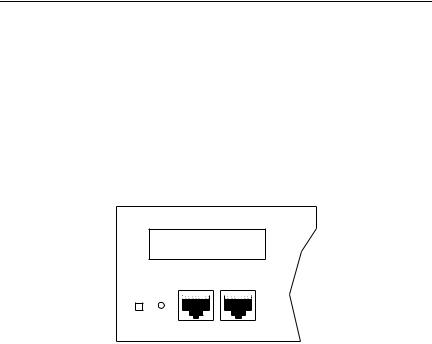
2.3COM 1/COM 2 PORT SPECIFICATIONS
The RJ45 COM 1 and COM 2 ports support Console, Modem, UPS, and SLIP applications. A description of each COM port application is listed below:
Note: Console is the only COM port application available at this time. Modem, UPS, and SLIP applications will be available in future TRXI releases.
TRXI-24A TOKEN RING HUB WITH LANVIEW®
DISPLAY RESET
COM 2 |
COM 1 |
Figure 2-2. COM 1/COM 2 Ports
Console
The COM 1 port, as default, supports access to a Local Management Console. The console supports a Digital Equipment Corporation VT 320™ terminal or PC emulation of the VT 320 terminal.
Modem
Both the COM 1 and COM 2 ports support access to Local Management using a modem.
UPS
The COM 2 port supports an Uninterruptible Power Supply (American Power Conversion only).
SLIP
The COM 1 and COM 2 ports support the Serial Line Internet Protocol.
Page 2-11
REQUIREMENTS/SPECIFICATIONS
2.4TPIM SPECIFICATIONS
TPIMs provide Ring In/Ring Out (RI/RO) connections that let you extend your network using a variety of media. Each TPIM has an embedded repeater that retimes all data.
The LNK (Link) LED on each TPIM provides the following information:
•Green - RI or RO active
•Red (TPIM-T1/T2/T4 only) - No Link (Autowrapped)
•Off - No Link (Wrapped or Disabled)
The following sections describe each TPIM.
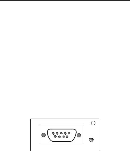
TPIM-T1
The TPIM-T1 is a female DB9 connector that supports STP cabling. Figure 2-3 shows TPIM-T1 pinouts for Ring Out and Ring In applications.
5 |
4 |
3 |
2 |
1 |
|
|
|
|
LNK |
|
9 |
8 |
7 |
6 |
|
|
|
|
TPIM-T1 |
RING OUT |
RING IN |
||
1. |
Transmit + |
1. |
Receive + |
2. |
Ground |
2. |
Ground |
3. |
+5V at 250 mA |
3. |
+5V at 250 mA |
4. |
Ground |
4. |
Ground |
5. |
Receive - |
5. |
Transmit - |
6. |
Transmit - |
6. |
Receive - |
7. |
Ground |
7. |
Ground |
8. |
Ground |
8. |
Ground |
9. |
Receive + |
9. |
Transmit + |
Figure 2-3. TPIM-T1 Pinouts
Page 2-12
REQUIREMENTS/SPECIFICATIONS
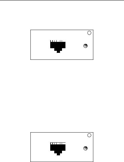
TPIM-T2
The TPIM-T2 is an RJ45 connector that supports UTP cabling. Figure 2-4 shows pinouts for Ring Out and Ring In applications.
|
|
|
|
|
|
|
|
|
1 2 3 4 5 6 7 8 |
|
LNK |
||||
|
|
|
|
|
|
|
|
|
|
|
|
|
|
|
TPIM-T2 |
|
|
|
|
|
|
|
|
|
|
|
|
|
|
|
|
|
|
|
|
|
|
|
|
|
|
|
|
|
|
|
|
RING OUT |
RING IN |
||
1. |
Not Used |
1. |
Not Used |
2. |
Not Used |
2. |
Not Used |
3. |
Receive - |
3. |
Transmit - |
4. |
Transmit + |
4. |
Receive + |
5. |
Transmit - |
5. |
Receive - |
6. |
Receive + |
6. |
Transmit + |
7. |
Not Used |
7. |
Not Used |
8. |
Not Used |
8. |
Not Used |
Figure 2-4. TPIM-T2 Pinouts
TPIM-T4
The TPIM-T4 is an RJ45 connector that supports STP cabling. Figure 2-5 shows pinouts for Ring Out and Ring In applications.
|
|
|
|
|
|
|
|
|
1 2 3 4 5 6 7 8 |
|
LNK |
||||
|
|
|
|
|
|
|
|
|
|
|
|
|
|
|
TPIM-T4 |
|
|
|
|
|
|
|
|
|
|
|
|
|
|
|
|
|
|
|
|
|
|
|
|
|
|
|
|
|
|
|
|
RING OUT |
RING IN |
||
1. |
Not Used |
1. |
Not Used |
2. |
Not Used |
2. |
Not Used |
3. |
Receive - |
3. |
Transmit - |
4. |
Transmit + |
4. |
Receive + |
5. |
Transmit - |
5. |
Receive - |
6. |
Receive + |
6. |
Transmit + |
7. |
Not Used |
7. |
Not Used |
8. |
Not Used |
8. |
Not Used |
Figure 2-5. TPIM-T4 Pinouts
Page 2-13
REQUIREMENTS/SPECIFICATIONS
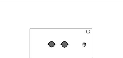
TPIM-F2
The TPIM-F2 shown in Figure 2-6 is an ST connector that supports Multimode fiber Optic cabling.
RX |
TX |
LNK |
|
|
|
|
|
TPIM-F2 |
Figure 2-6. The TPIM-F2
Note: The transmitter power levels and receive sensitivity levels given are Peak Power Levels after optical overshoot. A Peak Power Meter must be used to correctly compare the values given to those measured on any particular port. If Power Levels are being measured with an Average Power Meter, then 3 dBm must be added to the measurement to correctly compare those measured values to the values listed (i.e. -30.5 dBm peak=-33.5 dBm average).
Parameter |
Typical |
Worst |
Worst Case Typical |
|
Receive |
Value |
Case |
Budget |
Budget |
|
|
|
|
|
Sensitivity: |
-30.5 dBm |
-28.0 dBm |
— |
— |
Peak Input |
|
|
|
|
Power: |
-7.6 dBm |
-8.2 dBm |
— |
— |
Transmitter Power |
|
|
|
|
50/125 m |
|
|
|
|
fiber: |
-13.0 dBm |
-15.0 dBm |
13.0 dB |
17.5 dB |
62.5/125 m |
|
|
|
|
fiber: |
-10.0 dBm |
-12.0 dBm |
16.0 dB |
20.5 dB |
100/140 m |
|
|
|
|
fiber: |
-7.0 dBm |
-9.0 dBm |
19.0 dB |
23.5 dB |
Error Rate: |
Better than 10-10 |
|
|
|
Page 2-14
REQUIREMENTS/SPECIFICATIONS
TPIM-F3
The TPIM-F3 shown in Figure 2-7 is an ST connector that supports Single Mode fiber Optic cabling.
RX |
TX |
LNK |
|
|
|
|
|
TPIM-F3 |
Figure 2-7. The TPIM-F3
Note: Transmitter Power decreases as temperatures rise and increases as temperatures fall. Use the Output Power Coefficient to calculate increased or decreased power output for your operating environment. For example, the typical power output at 25°C is -16.4 dBm. For a 4°C temperature increase, multiply the typical coefficient
(-0.15 dBm) by four and add the result to typical output power (4 x -0.15 dBm + -16.4 = -17.0).
|
|
|
|
|
|
|
Maximum Sensitivity (-36.0) |
|
|
|
|
||||||
|
|
|
|
|
|
|
|
|
|
|
|
|
|
|
|
|
|
Receive |
|
|
|
|
|
|
Typical Sensitivity (-31.0) |
|
|
|
|
||||||
Sensitivity |
|
|
|
|
|
|
|
|
|
|
|
|
|
|
|
|
|
|
|
|
|
|
|
|
Minimum Sensitivity (-30.0) |
|
|
|
|
||||||
|
|
|
|
|
|
|
|
|
|
|
|
|
|
|
|
|
|
|
|
|
|
|
|
|
|
|
|
|
|
|
|
|
|
|
|
|
|
|
|
|
|
|
|
|
|
|
|
|
|
|
|
Minimum Receive Input (-9.72) |
|
|
|
|
|
|
|
|
|
|
|
|
|
|
|
|
|
|
|
Maximum |
|
|
|
|
|
|
|
|
|
|
|
|
|
|
|
Typical Receive Input (-7.5) |
|
|
|
|
|
|
|
|
|
|
|
|
|
|
|
|
|
|
|
Receive |
|
|
|
|
|
|
|
|
|
|
|
|
|
|
|
|
|
Input Power |
|
|
|
|
|
|
|
|
|
|
|
|
|
|
|
Maximum Receive Input (-6.99) |
|
|
|
|
|
|
|
|
|
|
|
|
|
|
|
|
|
|
|
|
|
|
|
|
|
|
|
|
|
|
|
|
|
|
|
|
|
|
|
|
|
|
|
|
|
|
|
|
|
|
|
|
|
|
|
Transmitter Power* |
|
|
|
|
|
|
|
|
|
|
|
Maximum Transmit Power (-12.0) |
|
||||
(At 25°C into |
|
|
|
|
|
|
|
|
|
|
|
|
|||||
|
|
|
|
|
|
|
|
|
|
|
Typical Transmit Power (-15.5) |
|
|||||
8.3/125 m fiber) |
|
|
|
|
|
|
|
|
|
|
|
|
|
|
|
|
|
|
|
|
|
|
|
|
|
|
|
|
|
|
|
|
|
|
|
|
|
|
|
|
|
|
|
|
|
|
|
Minimum Transmit Power (-21.0) |
|
||||
dBm |
-40 |
-35 |
-30 |
-25 |
-20 |
-15 |
-10 |
|
|
-5 |
|
0 |
|
||||
Less Power |
|
|
|
|
|
|
|
|
|
|
|
|
More Power |
||||
* Transmit Power |
|
|
|
|
Typical Power |
|
Minimum Power |
Maximum Power |
|||||||||
Coefficient |
|
|
|
|
|
|
-°0C.15dBm/ |
-0.12 dBm/°C |
|
|
-0.°18 dBm/ |
||||||
(See Note Below) |
|
|
|
|
|
|
|
||||||||||
Page 2-15

REQUIREMENTS/SPECIFICATIONS
Parameter |
Typical |
Minimum |
Maximum |
Transmitter Peak |
|
|
|
Wave Length |
1300 nm |
1270 nm |
1330 nm |
Spectral Width |
60 nm |
- |
100 nm |
Rise Time/ |
3.0 nsec |
2.7 nsec |
5.0 nsec |
Fall Time |
2.5 nsec |
2.2 nsec |
5.0 nsec |
Duty Cycle |
50.1% |
49.6% |
50.7% |
Bit Error Rate: |
Better than 10-10 |
|
|
Note: The transmitter power levels given above are Peak Power Levels after optical overshoot. You must use a Peak Power Meter to correctly compare the values given above to those measured on any particular port. If you are measuring power levels with an Average Power Meter, add 3 dBm to the average power measurement to correctly compare the average power values measured to the values listed above (i.e., -33.5 dBm average + 3 dB = -30.5 dBm peak).
Page 2-16
Loading...