

Page 1
The Complete Networking Solution
TRMF-2
802.5 MEDIA FILTER
INSTAL LATION INSTRUCTIONS
Cabletron Systems’ TRMF-2 Token Ring Media Filter
(Fig. 3) is a converter used to connect a PC adapter
card with a DB-9, shielded twisted-pair port to an
unshielded twisted-pair lobe link. The TRMF-2 matches
the impedance of 150 ohm STP (shielded twisted pair)
cable to 100 ohm UTP (unshielded twisted pair) cable
and filters the signal to limit the noise on the UTP cable.
The TRMF-2 has a male DB-9 connector, with captive
mounting screws, used to attach the media filter to the
PC adapter card. The TRMF-2 also has an RJ-45 port
to connect a voice-grade (IBM Type-3), unshielded
twisted pair lobe link to the media filter. This allows you
to incorporate twisted pair, voice grade cabling into
your token ring network. The other end of the UTP lobe
link can then be attached to an IEEE 802.5-compliant
token ring device, such as one of Cabletron Systems’
Token Ring Media Interface Modules in a Cabletron
Systems Multi Media Access Center (MMAC).
Ring Speed
The Cabletron Systems TRMF-2 operates in either a
4 Mbps or 16 Mbps token ring environment. No
switches or jumpers are used to set the ring speed for
the TRMF-2; it simply adapts to whatever the network’s
ring speed is. The TRMF-2 places the phantom drive
from the DB-9 port on the adapter card onto the UTP
lobe link.
INSTALLATION REQUIREMENTS
AND SPECIFICATIONS
NOTE: All conditions, guidelines, specifications, and
requirements included herein must be met to ensure
satisfactory network performance.
Hardware Requirements
Before installing the TRMF-2, ensure that there is a
token ring adapter card installed in the PC to which you
are attaching the TRMF-2. Check that the adapter card
has a female, DB-9, shielded twisted-pair port. Your
network connection should be an unshielded twistedpair lobe link, with an RJ-45 connector, to attach to the
TRMF-2.
TRMF-2
802.5 MEDIA FILTER
1
2
3
4
5
If this equipment does cause interference to radio or
television, which can be determined by turning the
equipment off and on, the user is encouraged to try to
correct the interference by reorienting the receiving
antenna, relocating the computer with respect to the
antenna, moving the computer away from the receiver,
or plugging the computer into a different outlet so that
the computer and the receiver are on different branch
circuits.
If necessary, the user should consult an experienced
radio/television technician for additional suggestions.
A helpful booklet on this subject is “How to Identify and
Resolve Radio TV Interference Problems,” prepared
by the Federal Communication Commission. This
booklet is available from the U.S. Government Printing
Office, Washington D.C. 20402 - Stock No. 004-00000345-4.
NOTICE
Cabletron Systems reserves the right to make changes
in specifications and other information contained in this
document without prior notice. The reader should in all
cases consult Cabletron Systems to determine whether
any such changes have been made.
The hardware, firmware, or software described in this
manual is subject to change without notice.
IN NO EVENT SHALL CABLETRON SYSTEMS BE
LIABLE FOR ANY INCIDENTAL, INDIRECT, SPECIAL,
OR CONSEQUENTIAL DAMAGES WHATSOEVER
(INCLUDING BUT NOT LIMITED TO LOST PROFITS)
ARISING OUT OF OR RELATED TO THIS MANUAL
OR THE INFORMATION CONTAINED IN IT, EVEN IF
CABLETRON SYSTEMS HAS BEEN ADVISED OF,
KNOWN, OR SHOULD HAVE KNOWN, THE
POSSIBILITY OF SUCH DAMAGES.
Copyright October 1991 by
Cabletron Systems, Inc., 35 Industrial Way,
P.O. Box 5005, Rochester, NH 03867-5005
All Rights Reserved
Printed in the United States of America
Order number: 9030552
TRMF-2, and MMAC are trademarks of Cabletron
Systems, Inc. IBM is a registered trademark of
International Business Machines Corporation.
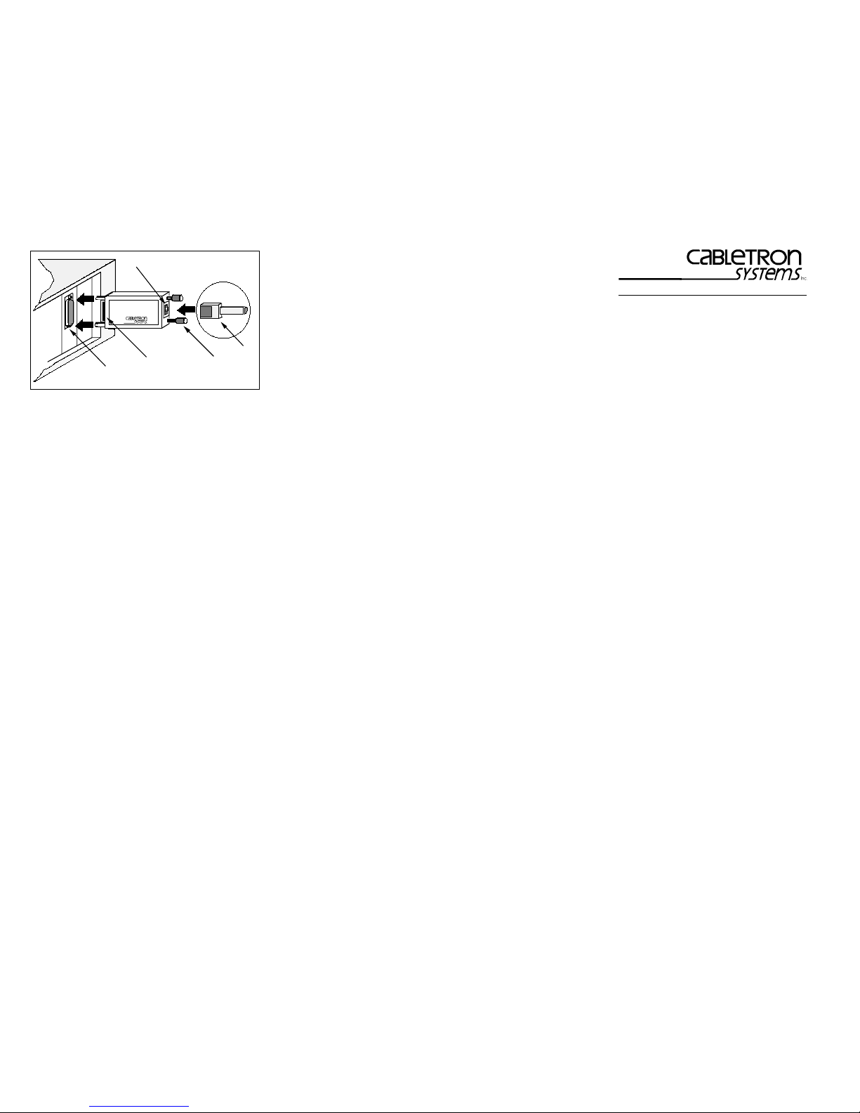
Figure 3. Installing The TRMF-2
Save the shipping container and material in the event
that the unit has to be returned. Should you encounter
a problem, contact Cabletron Systems Technical
Support.
If you need additional support related to the TRMF-2,
or if you have any questions, comments, or suggestions
concerning these instructions, contact Cabletron
Systems Technical Support at:
Cabletron Systems, Inc.
35 Industrial Way
P.O. Box 5005
Rochester, NH 03867-5005
Phone: (603) 332-9400
FCC NOTICE
This device complies with Part 15 of FCC rules.
Operation is subject to the following two conditions: (1)
this device may not cause harmful interference, and (2)
this device must accept any interference received,
including interference that may cause undesired
operation.
NOTE: This equipment has been tested and found to
comply with the limits for a Class A digital device
pursuant to Part 15 of FCC Rules. These limits are
designed to provide reasonable protection against
harmful interference when the equipment is operated
in a commercial environment. This equipment uses,
generates, and can radiate radio frequency energy and
if not installed in accordance with the operator’s manual,
may cause harmful interference to radio communications. Operation of this equipment in a residential
area is likely to cause interference in which case the
user will be required at his own expense to correct the
interference.
Page 2
Network Requirements
The reliability of the network is determined by the
quality of the connections, the length of the cables and
other conditions of the installation. Following is a
summary of network requirements for this equipment.
Cable Types
Type 1 - Each TRMF-2 has a male DB-9 connector,
permanently attached. This connector is configured for
connecting two shielded twisted pairs of 22 AWG solid
wire to transmit and receive data.
Type 3 - A UTP lobe link attached to the TRMF-2
usually consists of two unshielded twisted pairs of 24
AWG solid wire for data or voice communication, such
as telephone lines.
Cable Length
STP connection - fixed, with captive mounting screws
for attachment to PC adapter’s DB-9 connector.
UTP - The acceptable maximum lobe link length for
voice grade cabling is dependent on several factors,
including token ring speed. Refer to the manual for the
concentrator to which your TRMF-2 is attached.
Attenuation
Exceeding attenuation specifications can result in poor
network performance. The attenuation values include
the attenuation of the cables, connectors, and patch
panels. There are two possible ring speeds, therefore
both frequencies are listed, 4.0 Mbps and 16 Mbps.
Since the STP connector mounts directly on the PC
adapter connector, only the attenuation values for the
UTP lobe link are listed. The maximum attenuation for
Voice Grade UTP (IBM Type 3) is 56 dB/km at 4 Mbps,
and 131 dB/km at 16 Mbps.
Impedance
The STP cable must have an impedance of 150 ohms
±10%, and the UTP cable must have an impedance of
100 ohms ±15%.
Crosstalk/Noise
Crosstalk is caused by signal coupling between the
different cable pairs contained within a multiple-pair
cable bundle. In shielded-pair cables, the effects of
crosstalk are minimized. The unshielded cable must be
a twisted-pair cable in order to reduce or limit crosstalk.
Noise can be caused by either crosstalk or externally
induced impulses. If noise-induced errors are suspected,
it may be necessary to re-route cabling away from
potential noise sources (motors, switching equipment,
high current equipment), or to ensure that the electrical
wiring in the area is properly connected and grounded.
Temperature
The attenuation of PVC insulated cable varies
significantly with temperature. At temperatures greater
than 40°C, Cabletron strongly recommends that you
use plenum-rated cables to ensure that cable
attenuation remains within specifications. Check the
cable manufacturer’s specifications.
OPERATING SPECIFICATIONS
The operating specifications for Cabletron Systems’
TRMF-2 are listed below. Cabletron Systems reserves
the right to change these specifications at any time
without notice.
Figure 1. DB-9 Connector
Type: DB-9 Connector
Pin 1 RX+ Pin 6 RXPin 2 No Connection Pin 7 No Connection
Pin 3 No Connection Pin 8 No Connection
Pin 4 No Connection Pin 9 TX+
Pin 5 TXConnector Shell: Chassis Ground
NOTE: The TRMF-2 does not require power from the
DB-9 port.
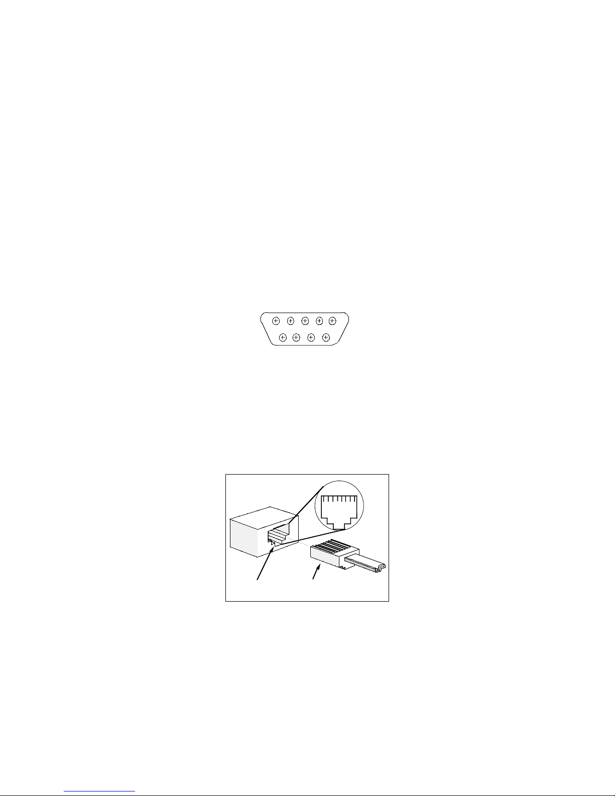
RJ-45 Port RJ-45 Connector
Figure 2. RJ-45 Connections
12345678
1
6
5
9
RJ-45 Interface
Type: RJ-45 port
Pin 1 No Connection Pin 5 RxPin 2 No Connection Pin 6 TX+
Pin 3 TX- Pin 7 No Connection
Pin 4 RX+ Pin 8 No Connection
Environmental Requirements
Operating Temperature:
0° to +60°C (32° to 140°F)
Operating Humidity:
10% to 90% (non-condensing)
Safety
Designed in accordance with UL478, UL910, NEC 7252(b), CSA, IEC, TUV, VDE class A. Meets FCC, Part
15, Class A limits.
WARNING: It is the responsibility of the person who
sells the system of which the TRMF-2 will be a part to
ensure that the total system meets allowed limits of
conducted and radiated emissions.
Physical Properties
Dimensions:
3.26 L x 1.33 H inches
8.28 L x 3.36 H cm
INSTALLING THE TRMF-2
The installation of the TRMF-2 is a quick and simple
procedure. Before installing the TRMF-2, be sure you
have meet all the requirements listed under Installation
Requirements and Specifications. Failure to do so
will result in improper operation of your network.
To install the TRMF-2:
1. Turn off the power for your PC.
2. Using the attached captive mounting screws, connect
the DB-9 connector (1, Figure 3) to the DB-9 port (2,
Figure 3) on the adapter card.
3. Tighten the screws (3, Figure 3) to secure the
connector to the port.
4. Attach an RJ-45 connector (4, Figure 3) from the
UTP lobe link to the RJ-45 port (5, Figure 3) on the
TRMF-2.
5. Power up your PC.
The TRMF-2 is now ready for operation.
 Loading...