

Page 1

BOOKTITLE2 OPTIONAL
TRBMIM/TRBMIM-T
LOCAL MANAGEMENT
USER’S GUIDE
Page 2

Page 3

NOTICE
Cabletron Systems reserves the right to make changes in specifications and other information
contained in this document without prior notice. The reader should in all cases consult Cabletron
Systems to determine whether any such changes have been made.
The hardware, firmware, or software described in this manual is subject to change without notice.
IN NO EVENT SHALL CABLETRON SYSTEMS BE LIABLE FOR ANY INCIDENTAL,
INDIRECT, SPECIAL, OR CONSEQUENTIAL DAMAGES WHATSOEVER (INCLUDING BUT
NOT LIMITED TO LOST PROFITS) ARISING OUT OF OR RELATED TO THIS MANUAL OR
THE INFORMATION CONTAINED IN IT, EVEN IF CABLETRON SYSTEMS HAS BEEN
ADVISED OF, KNOWN, OR SHOULD HAVE KNOWN, THE POSSIBILITY OF SUCH
DAMAGES.
Copyright 1996 by Cabletron Systems, Inc., P.O. Box 5005, Rochester, NH 03866-5005
All Rights Reserved
Printed in the United States of America
Order Number: 9030857-03 July 1996
SPECTRUM, LANVIEW
TRBMIM-T, TRMM, TRMMIM, TRMIM
Inc.
IBM
and
LAN Net Manager
Corporation.
DEC, VT200
CompuServe
All other product names mentioned in this manual may be trademarks or registered trademarks of
their respective companies.
, and
VT300
is a trademark of Compuserve, Inc.
, and
Remote LANVIEW
, and
are registered trademarks of International Business Machines
are trademarks of Digital Equipment Corporation.
are registered trademarks and
MMAC
are trademarks of Cabletron Systems,
TRBMIM,
Printed on Recycled Paper
i
Page 4

NOTICE
FCC NOTICE
This device complies with Part 15 of the FCC rules. Operation is subject to the following two
conditions: (1) this device may not cause harmful interference, and (2) this device must accept any
interference received, including interference that may cause undesired operation.
NOTE:
device, pursuant to Part 15 of the FCC rules. These limits are designed to provide reasonable
protection against harmful interference when the equipment is operated in a commercial environment.
This equipment uses, generates, and can radiate radio frequency energy and if not installed in
accordance with the operator’s manual, may cause harmful interference to radio communications.
Operation of this equipment in a residential area is likely to cause interference in which case the user
will be required to correct the interference at his own expense.
WARNING:
party responsible for compliance could void the user’s authority to operate the equipment.
This equipment has been tested and found to comply with the limits for a Class A digital
Changes or modifications made to this device which are not expressly approved by the
DOC NOTICE
This digital apparatus does not exceed the Class A limits for radio noise emissions from digital
apparatus set out in the Radio Interference Regulations of the Canadian Department of
Communications.
Le présent appareil numérique n’émet pas de bruits radioélectriques dépassant les limites applicables
aux appareils numériques de la class A prescrites dans le Règlement sur le brouillage radioélectrique
édicté par le ministère des Communications du Canada.
VCCI NOTICE
This equipment is in the 1st Class Category (information equipment to be used in commercial and/or
industrial areas) and conforms to the standards set by the Voluntary Control Council for Interference
by Information Technology Equipment (VCCI) aimed at preventing radio interference in commercial
and/or industrial areas.
Consequently , when used in a residential area or in an adjacent area thereto, radio interference may be
caused to radios and TV receivers, etc.
Read the instructions for correct handling.
ii
Page 5

NOTICE
CABLETRON SYSTEMS, INC. PROGRAM LICENSE AGREEMENT
IMPORTANT:
This document is an agreement between you, the end user, and Cabletron Systems, Inc. (“Cabletron”)
that sets forth your rights and obligations with respect to the Cabletron software program (the
“Program”) contained in this package. The Program may be contained in firmware, chips or other
media. BY UTILIZING THE ENCLOSED PRODUCT, YOU ARE AGREEING TO BECOME
BOUND BY THE TERMS OF THIS AGREEMENT, WHICH INCLUDES THE LICENSE AND
THE LIMITATION OF WARRANTY AND DISCLAIMER OF LIABILITY. IF YOU DO NOT
AGREE TO THE TERMS OF THIS AGREEMENT, PROMPTLY RETURN THE UNUSED
PRODUCT TO THE PLACE OF PURCHASE FOR A FULL REFUND.
Before utilizing this product, carefully read this License Agreement.
CABLETRON SOFTWARE PROGRAM LICENSE
1. LICENSE
package subject to the terms and conditions of this License Agreement.
You may not copy, reproduce or transmit any part of the Program except as permitted by the
Copyright Act of the United States or as authorized in writing by Cabletron.
2. OTHER RESTRICTIONS. You may not reverse engineer, decompile, or disassemble the
Program.
3. APPLICABLE LA W. This License Agreement shall be interpreted and governed under the laws
and in the state and federal courts of New Hampshire. You accept the personal jurisdiction and
venue of the New Hampshire courts.
. You have the right to use only the one (1) copy of the Program provided in this
EXCLUSION OF WARRANTY AND DISCLAIMER OF LIABILITY
1. EXCLUSION OF
writing, Cabletron makes no warranty, expressed or implied, concerning the Program (including
its documentation and media).
CABLETRON DISCLAIMS ALL WARRANTIES, OTHER THAN THOSE SUPPLIED TO
YOU BY CABLETRON IN WRITING, EITHER EXPRESSED OR IMPLIED, INCLUDING
BUT NOT LIMITED TO IMPLIED WARRANTIES OF MERCHANTABILITY AND
FITNESS FOR A PARTICULAR PURPOSE, WITH RESPECT TO THE PROGRAM, THE
ACCOMPANYING WRITTEN MATERIALS, AND ANY A CCOMPANYING HARDW ARE.
2. NO LIABILITY FOR CONSEQUENTIAL DAMAGES. IN NO EVENT SHALL
CABLETRON OR ITS SUPPLIERS BE LIABLE FOR ANY DAMAGES WHATSOEVER
(INCLUDING, WITHOUT LIMITATION, DAMAGES FOR LOSS OF BUSINESS,
PROFITS, BUSINESS INTERRUPTION, LOSS OF BUSINESS INFORMATION, SPECIAL,
INCIDENTAL, CONSEQUENTIAL, OR RELIANCE DAMAGES, OR OTHER LOSS)
ARISING OUT OF THE USE OR INABILITY TO USE THIS CABLETRON PRODUCT,
EVEN IF CABLETRON HAS BEEN ADVISED OF THE POSSIBILITY OF SUCH
DAMAGES. BECAUSE SOME STATES DO NOT ALLOW THE EXCLUSION OR
LIMITATION OF LIABILITY FOR CONSEQUENTIAL OR INCIDENTAL DAMAGES, OR
ON THE DURATION OR LIMITATION OF IMPLIED WARRANTIES, IN SOME
INSTANCES THE ABOVE LIMITATIONS AND EXCLUSIONS MAY NOT APPLY TO
YOU.
WARRANTY. Except as may be specifically provided by Cabletron in
iii
Page 6

NOTICE
UNITED STATES GOVERNMENT RESTRICTED RIGHTS
The enclosed product (a) was developed solely at private expense; (b) contains “restricted computer
software” submitted with restricted rights in accordance with Section 52227-19 (a) through (d) of the
Commercial Computer Software - Restricted Rights Clause and its successors, and (c) in all respects
is proprietary data belonging to Cabletron and/or its suppliers.
For Department of Defense units, the product is licensed with “Restricted Rights” as defined in the
DoD Supplement to the Federal Acquisition Regulations, Section 52.227-7013 (c) (1) (ii) and its
successors, and use, duplication, disclosure by the Government is subject to restrictions as set forth in
subparagraph (c) (1) (ii) of the Rights in Technical Data and Computer Software clause at
252.227-7013. Cabletron Systems, Inc., 35 Industrial Way, Rochester, New Hampshire 03867-0505.
iv
Page 7

CONTENTS
CHAPTER 1 INTRODUCTION
1.1 Document Conventions...............................................................1-1
1.2 Getting Help.................................................................................1-2
1.3 Using This Manual.......................................................................1-2
1.4 LM Structure................................................................................1-4
1.5 Operational Modes And LM Access............................................1-6
CHAPTER 2 ACCESSING LOCAL MANAGEMENT
2.1 Management Terminal Requirements.........................................2-1
2.2 Connecting A VT-Series Terminal...............................................2-1
2.3 Connecting A PC.........................................................................2-2
2.4 Connecting A Modem..................................................................2-3
2.5 Configuring Terminal Setup Parameters.....................................2-4
2.6 Configuring Modem Setup Parameters.......................................2-5
2.7 Accessing Local Management.....................................................2-6
2.7.1 Accessing LM Via Telnet ................................................2-8
2.7.2 Accessing LM Via Remote Modem Connection .............2-8
2.7.3 Disconnecting A Current LM User ..................................2-8
CHAPTER 3 WORKING WITH LOCAL MANAGEMENT
3.1 Describing Keyboard Functions...................................................3-1
3.2 Accessing Screens......................................................................3-2
3.3 LM Screen Elements...................................................................3-2
3.3.1 Describing LM Screen Fields.......................................... 3-3
3.3.2 Working With Input And Toggle Fields ...........................3-3
3.3.3 LM Application Messages............................................... 3-4
3.3.4 Exiting An LM Screen .....................................................3-5
3.3.5 Exiting LM.......................................................................3-5
CHAPTER 4 DEVICE SETUP MENU
4.1 The System Level Screen ...........................................................4-2
4.1.1 Setting The System Date And System Time ..................4-3
4.1.2 Setting The Station And FNB IP Addresses ...................4-4
4.1.3 Setting The Subnet Mask ...............................................4-4
4.1.4 Setting Enable Beacon Recovery Fields ........................4-5
4.1.5 Specifying Locally Administered MAC Addresses..........4-8
v
Page 8

CONTENTS
4.2 The SNMP Community Names Screen .......................................4-9
4.2.1 Establishing Community Names ...................................4-10
4.3 The SNMP Traps Screen...........................................................4-11
4.3.1 Setting SNMP Traps......................................................4-12
4.4 The Ring Security Screen..........................................................4-13
4.4.1 Specifying The Ring Interface.......................................4-14
4.4.2 Specifying A Ring Security Mode..................................4-14
4.4.3 Building The Allowed List Automatically........................4-16
4.4.4 Manually Adding Stations To The Allowed List.............4-16
4.4.5 Deleting Stations From The Allowed List ......................4-17
4.4.6 Viewing The Station Address List..................................4-17
4.5 The Bridge Setup Screen...........................................................4-18
4.5.1 Implementing Parameter Changes................................4-18
4.5.2 Assigning Ring Numbers...............................................4-19
4.5.3 Specifying Hop Count Limits.........................................4-20
4.5.4 Specifying Which Broadcast Frames To Limit...............4-20
4.5.5 Enabling And Disabling Single Route Broadcasts.........4-21
4.5.6 Assigning A Bridge Number..........................................4-22
4.5.7 Specifying The Single Route Broadcast Mode..............4-22
4.5.8 Assigning The Bridge Label ..........................................4-24
4.5.9 Assigning The Bridge Path Cost ...................................4-24
4.6 The LAN Net Manager Assignment Screen...............................4-25
4.6.1 Creating Passwords......................................................4-26
4.6.2 Enabling Frame Forwarding..........................................4-27
CHAPTER 5 DEVICE STATUS MENU
5.1 The Chassis Status View Screen.................................................5-2
5.1.1 Describing Information/Configuration Fields ...................5-2
5.1.2 Selecting A Screen Mode................................................5-4
5.1.3 Viewing Next/Previous Screens......................................5-5
5.1.4 Specifying Screen Update Intervals................................5-6
5.1.5 Using The Operational Mode Screen..............................5-6
5.1.6 Using The Administrative Mode Screen..........................5-7
5.1.7 Using The Ring Out Enable Mode Screen....................5-10
5.2 The Component Status View Screen.......................................5-10
CHAPTER 6 DEVICE STATISTICS SCREEN
6.1 Specifying The Ring.....................................................................6-2
6.2 Specifying A Counter Mode .........................................................6-2
6.2.1 Using The Accumulative Counter Mode..........................6-3
vi
Page 9

CONTENTS
6.3 Specifying The Screen Update Interval.......................................6-3
6.4 Describing Statistical And Informational Fields ...........................6-4
6.4.1 General Statistics............................................................ 6-4
6.4.2 Isolating Errors................................................................ 6-4
6.4.3 Ring Information .............................................................6-6
6.4.4 Non-Isolating Errors........................................................ 6-7
CHAPTER 7 BRIDGE STATISTICS SCREEN
7.1 Specifying A Counter Mode.........................................................7-1
7.1.1 Using The Accumulative Counter Mode .........................7-2
7.2 Specifying The Screen Update Interval.......................................7-2
7.3 Describing Bridge Statistics.........................................................7-3
CHAPTER 8 SNMP TOOLS SCREEN
8.1 Describing SNMP Tools Screen Fields .......................................8-2
8.2 Specifying A MIB Community Name ...........................................8-4
8.3 Getting And Setting Variables .....................................................8-4
8.4 Scrolling Through MIB Variables.................................................8-7
8.4.1 Using The Walk Command............................................. 8-7
8.4.2 Using The Cycles Command..........................................8-8
8.4.3 Using The Step Command .............................................8-8
8.4.4 Using The Repeat Command .........................................8-8
INDEX
vii
Page 10

CONTENTS
viii
Page 11

CHAPTER 1
INTRODUCTION
Welcome to the
Guide
. This manual describes how to use Local Management (LM)
TRBMIM/TRBMIM-T Local Management User’s
applications to configure and monitor the TRBMIM/TRBMIM-T on a
Token Ring network. This manual is intended for all users of the
TRBMIM/TRBMIM-T, who should have a basic working knowledge of
the IEEE 802.5 standard for Token Ring networks, components used in
Token Ring networks, and Source-Route (SR) bridging concepts.
See the
TRBMIM-T User’s Guide
TRMM, TRBMIM, & TRMMIM Installation Guide
included with the TRBMIM-T and the
included with the
TRBMIM for information specifying bridge/management module
capabilities and configuration, installation, operation, cabling, and
troubleshooting procedures.
1.1 DOCUMENT CONVENTIONS
Document conventions are listed as follows:
•
Bold Italics
and other publications
is used for references to Cabletron Systems documents
The Local Management screen font as it appears on the
•
screen
is used for references to LM screen f ields in steps describing
how to work with LM applications. For example:
•
NOTE
CAUTION
-
Select the
-
Select the
Bold
!
is used for keyboard functions, i.e.,
Note calls your attention to information of special importance.
Caution calls your attention to information essential to avoid
damage to software, equipment, or network configuration
settings.
Subnet Mask
SAVE
....
field ....
Enter
key,
arrow
keys
1-1
Page 12

INTRODUCTION
1.2 GETTING HELP
If you need technical assistance or have any questions, comments, or
suggestions concerning this manual, contact Cabletron Systems Technical
Support Department using any of the following methods:
By phone (603) 332-9400
Monday-Friday; 8 a.m. – 8 p.m. Eastern Time
By CompuServe GO CTRON from any ! prompt
By Internet mail support@ctron.com
By FTP ctron.com or 134.141.197.25
Login
Password
anonymous
your email address
1.3 USING THIS MANUAL
This manual’s contents is organized as follows:
Chapter 1,
Introduction
, describes conv entions used in this manual, how
to get technical help, and the organizational structure of this manual.
It also describes LM applications accessible for each
TRBMIM/TRBMIM-T operational mode.
Chapter 2,
Accessing Local Management
, describes how to set up the
management terminal (VT-series terminal or PC) connection via
console-cable or remote-modem connection. It also describes
management-terminal and modem-communication parameters and how to
access LM via Telnet.
Chapter 3,
Working with Local Management
, describes how to work
with Local Management menus and screens.
Chapter 4,
Device Setup Menu
, describes how to use the System Level
screen to setup system parameters; the SNMP Community Names screen
to setup bridging parameters; the SNMP Traps screen to setup trap
destinations; the Ring Security screen to manage access to the ring; the
Bridge Setup screen to setup Source-Route bridging parameters; and the
LAN Net Manager Assignment screen to manage LAN Net Manager
software access to TRBMIM/TRBMIM-T management resources.
1-2
Page 13

INTRODUCTION
Chapter 5,
Device Status Menu
, describes how to use the Chassis Status
screen to manage FNB backplane connectivity between MIMs in the
MMAC and to enable or disable network ports under
TRBMIM/TRBMIM-T management control. It also describes how to
view which system components and resources are active in the
TRBMIM/TRBMIM-T using the Component Status screen.
Chapter 6,
Device Statistics Screen,
describes how to monitor network
performance on both the FNB ring and the ring interfacing with the
bridge Station port.
Chapter 7,
Bridge Statistics Screen,
describes how to monitor bridge
traffic on both the FNB port and the bridge Station port.
Chapter 8,
SNMP Tools Screen
, describes how to access and perform
SNMP operations on TRBMIM/TRBMIM-T Management Information
Base (MIB) objects.
1-3
Page 14

INTRODUCTION
1.4 LM STRUCTURE
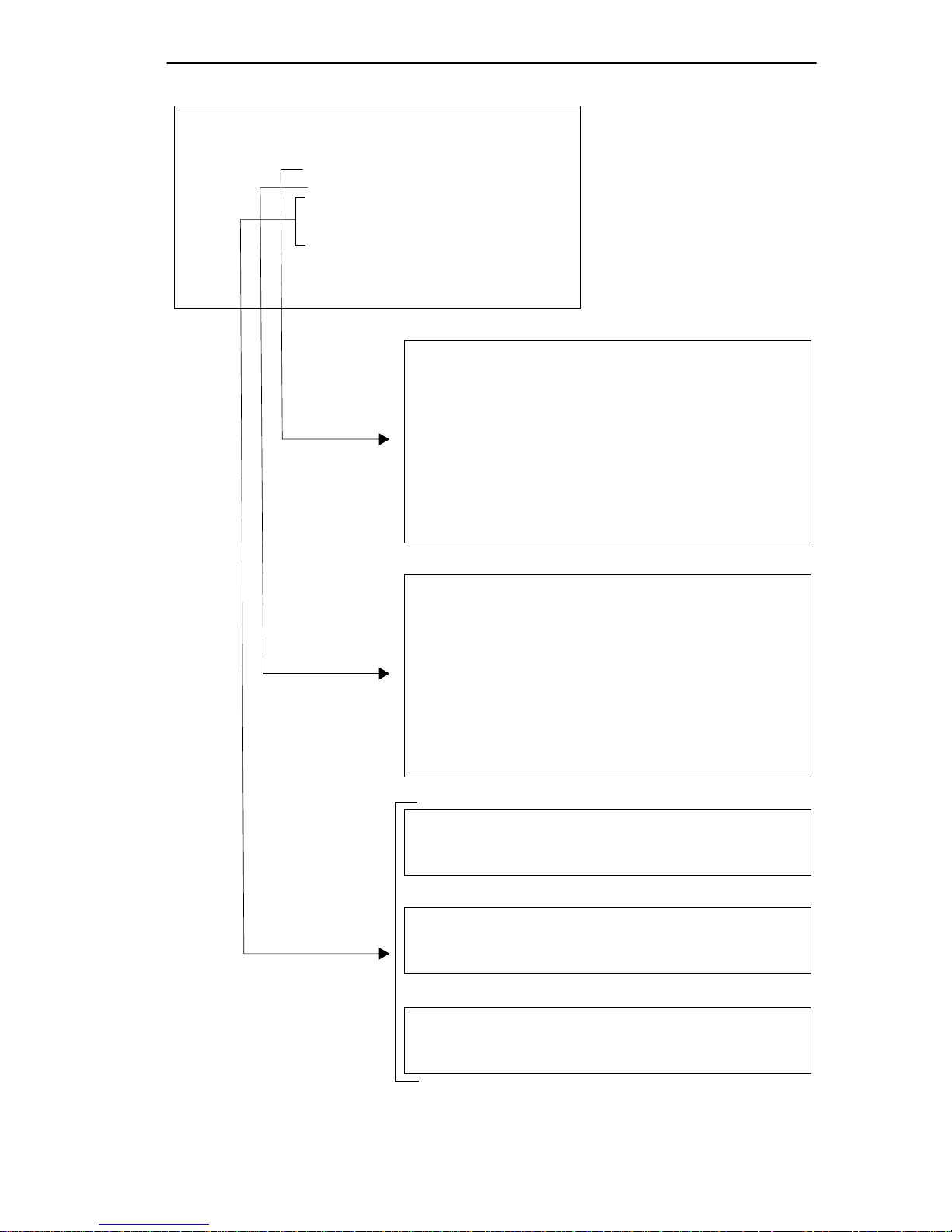
The Main Menu screen serves as the gateway to all LM screens, as
indicated in Figure 1-1.
The following menu selections are available from the Main Menu:
• Device Setup menu
From the Device Setup menu, you can select these applications:
-
System Level screen
-
SNMP Community Names screen
-
SNMP Traps screen
-
Ring Security screen
-
Bridge Setup screen
-
LAN Net Manager Assignment screen
• Device Status menu
From the Device Status menu, you can select these applications:
-
Chassis Status View screen
-
Component Status View screen
The following application screens are also available from the Main Menu:
• Bridge Statistics screen
• SNMP Tools screen
• Device Statistics screen
See Chapter 2 for information on accessing the TRBMIM/TRBMIM-T
LM Password screen and Chapter 3 for information on accessing and
working with LM screens.
1-4
Page 15
INTRODUCTION
TRBMIM Local Management
DEVICE SETUP
DEVICE STATUS
DEVICE STATISTICS
BRIDGE STATISTICS
SNMP TOOLS
Menu
Flash Image Version: x.xx.xx
MAIN MENU
TRBMIM Local Management
EXIT
Flash Image Version: x.xx.xx
DEVICE SETUP
SYSTEM LEVEL
SNMP COMMUNITY NAMES
SNMP TRAPS
RING SECURITY
BRIDGE SETUP
LAN NET MANAGER
RETURN
Menu
Applications
TRBMIM Local Management
CHASSIS STATUS
COMPONENT STATUS
TRBMIM Local Management
DEVICE STATISTICS
TRBMIM Local Management
SOURCE ROUTING BRIDGE STATISTICS
TRBMIM Local Management
Flash Image Version: x.xx.xx
STATUS SETUP
RETURN
Flash Image Version: x.xx.xx
Flash Image Version: x.xx.xx
Flash Image Version: x.xx.xx
SNMP TOOLS
Figure 1-1 LM Structure
1-5
Page 16

INTRODUCTION
1.5 OPERATIONAL MODES AND LM ACCESS
The number of LM applications you can access is contingent upon which
operational mode you have specified for the TRBMIM/TRBMIM-T. The
TRBMIM/TRBMIM-T can be configured to operate as a dedicated
Source-Route bridge or as a combination bridge and Token Ring
management module. See the
the TRBMIM-T and the
Guide
included with the TRBMIM for information about operational
TRMM, TRBMIM, & TRMMIM Installation
TRBMIM-T User’s Guide
mode specifications and selecting an operational mode.
The title of a LM screen indicates the current operating mode of the
TRBMIM/TRBMIM-T.
When the TRBMIM/TRBMIM-T is in the Bridge-Only mode, the LM
screen displays this title:
“TRBMIM BRIDGE LOCAL MANAGEMENT”
included with
When the TRBMIM/TRBMIM-T is in the Bridge/Management mode, the
LM screen displays this title:
“TRBMIM CHASSIS LOCAL MANAGEMENT”
Table 1-1 lists LM applications you can access when the
TRBMIM/TRBMIM-T is configured to operate in either operational
mode.
1-6
Page 17

INTRODUCTION
Table 1-1 LM Access Per Operational Modes
OPERATIONAL MODE
Bridge-Only
LM APPLICATION
System Level
SNMP Community Names Yes Yes
SNMP Traps Yes Yes
Ring Security No Yes
Bridge Setup Yes Yes
LAN Net Manager Yes Yes
Chassis Status View No Yes
Component Status View Yes Yes
Device Statistics No Yes
Bridge Statistics Yes Yes
SNMP Tools Yes Yes
Note
: The degree of access to these applications depends on your password
status. See Section 4.2 to establish password privileges.
Access
Yes-limited
No access to Beacon
Recovery fields
Bridge/Management
Access
Yes
The next chapter describes how to connect a management terminal or PC
to the TRBMIM/TRBMIM-T LM-access Console port and how to access
the LM Password screen.
1-7
Page 18

INTRODUCTION
1-8
Page 19

CHAPTER 2
ACCESSING LOCAL MANAGEMENT
This chapter describes how to access LM via a direct or remote
management terminal connection. It describes management terminal
requirements and how to connect a VT-series terminal, a PC, and a
modem to the TRBMIM/TRBMIM-T. It also describes terminal and
modem setup parameters for the connection and requirements for
establishing an in-band connection to LM via Telnet.
2.1 MANAGEMENT T ERMINAL REQUIREMENTS
The following terminals can be used to access LM:
• Digital Equipment Corporation VT-series terminal or VT-type
terminal running VT-series software
• IBM or compatible PC running a VT-series emulation program
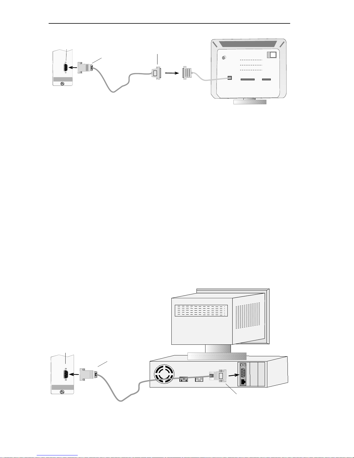
2.2 CONNECTING A VT-SERIES TERMINAL
Use the RS-232 console cable and the RJ45-to-DB25 VT-series adaptor
shipped with the TRBMIM/TRBMIM-T to connect the VT-series
terminal, as shown in Figure 2-1.
To connect the VT-series terminal:
1. Insert the cable’s DB9 connector into the LM Console port.
2. Attach the VT-series RJ45-to-DB25 adaptor to the RJ45 connector at
the other end of the cable.
3. Connect the adaptor into the appropriate serial communications port
on the VT-series terminal, as specified in the user instructions
included with the terminal.
See Section 2.5 for terminal setup parameters.
2-1
Page 20
ACCESSING LOCAL MANAGEMENT
LM Console Port
VT-Series RJ45-to-DB25
Adaptor
DB9 Console
Connector
TOKEN RING BRIDGE
C
O
N
S
O
L
E
Vt T erminal
Figure 2-1 Connecting a VT-Series Terminal (Example)
2.3 CONNECTING A PC
Use the RS-232 console cable and the RJ45-to-DB9 PC adaptor shipped
with the TRBMIM/TRBMIM-T to connect the PC, as shown in
Figure 2-2.
To connect the PC:
1. Insert the cable’s DB9 connector into the LM Console port.
2. Attach the PC RJ45-to-DB9 adaptor to the RJ45 connector at the other
end of the cable.
3. Connect the adaptor into the appropriate serial communications port
on the PC, as specified in the user instructions included with the PC.
See Section 2.5 for terminal setup parameters.
LM Console Port
DB9 Console
Connector
PC
PC RJ45-to-DB9
Adaptor
TOKEN RING BRIDGE
C
O
N
S
O
L
E
Figure 2-2 Connecting a PC (Example)
2-2
Page 21
ACCESSING LOCAL MANAGEMENT
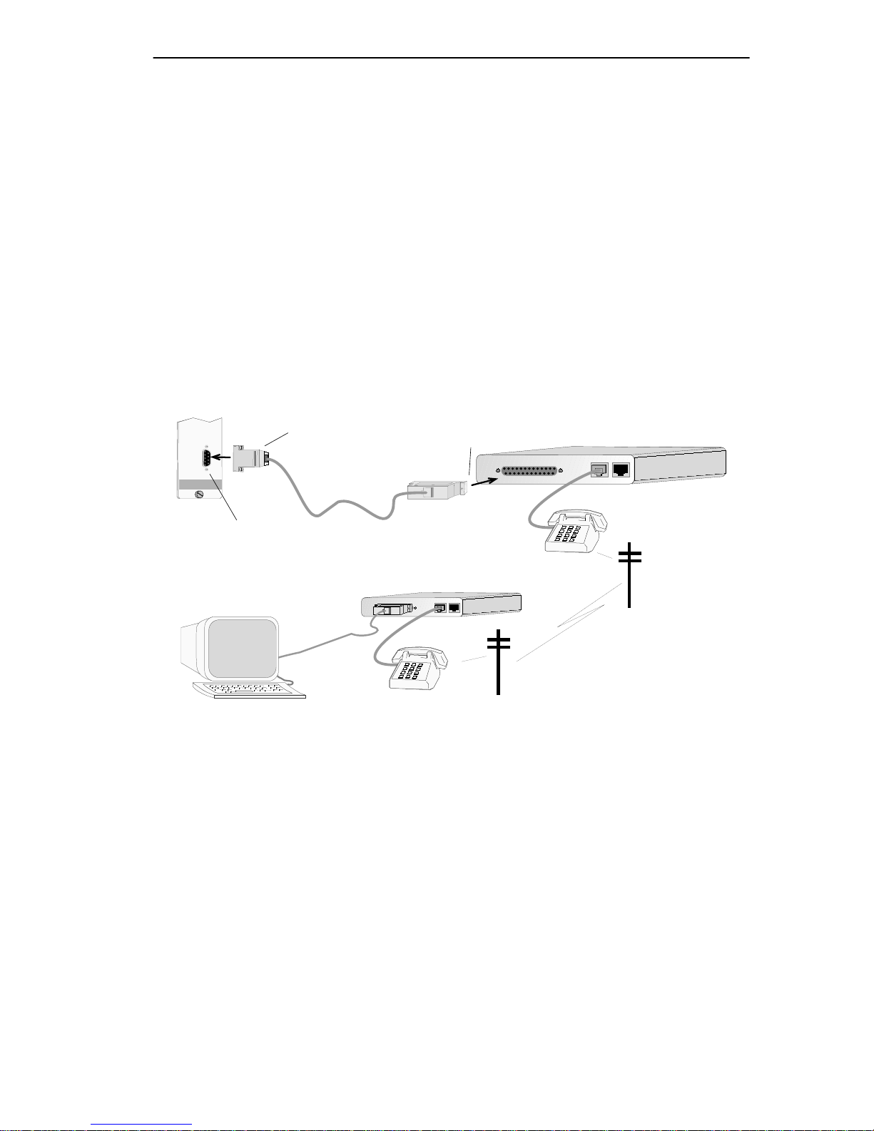
2.4 CONNECTING A MODEM
Use the RS-232 console cable and the RJ45-to-DB25 modem adaptor
shipped with the TRBMIM/TRBMIM-T to connect the modem, as shown
in Figure 2-3.
To establish the modem connection:
1. Insert the cable’s DB9 connector into the LM Console port.
2. Attach the RJ45-to-DB25 modem adaptor to the RJ45 connector at the
other end of the cable and insert it into the modem’s communications
port.
See Section 2.6 for modem setup parameters.
C
O
N
S
O
L
E
TOKEN RING BRIDGE
LM Console Port
Terminal
DB9 Console
Connector
Modem RJ45-to-DB25
Adaptor
Figure 2-3 Connecting a Modem (Example)
Modem
2-3
Page 22

ACCESSING LOCAL MANAGEMENT
2.5 CONFIGURING TERMINAL SETUP PARAMETERS
Table 2-1 lists the setup parameters for the management terminal. If you
are using a VT terminal, press F3 or the Setup key to access the Setup
Directory. For a PC running a VT-terminal emulation program, refer to
the documentation included with the program for specific instructions on
setting VT-series-equivalent communication parameters.
Table 2-1 Terminal Settings for LM Console
Menu Parameter Setting
Display Setup
General Setup
Communications
Setup
Columns 80 Columns
Controls Interpret controls
Auto wrap No Auto wrap
Text Cursor No Cursor
Mode VT100, 7 bit control
Cursor keys Normal cursor keys
Transmit
Receive Receive = transmit
Bits, parity 8 Bits, no parity
Stop Bit 1 Stop Bit
Local Echo No Local Echo
(values from 2400 to
19,200 accepted)
Keyboard Setup
2-4
Port Data Leads Only
Auto Answerback No Auto Answerback
Keys Typewriter keys
Margin bell No Margin bell
Auto Answerback No Auto Answerback
Page 23

ACCESSING LOCAL MANAGEMENT
2.6 CONFIGURING MODEM SETUP PARAMETERS
Table 2-2 lists setup steps and parameters for the PC, the modem attached
to the PC and the modem attached to the TRBMIM/TRBMIM-T. You
enter settings in the terminal-emulation application included with the PC.
Table 2-2 Modem Configuration Setup Instructions
1. To configure the PC, enter the following parameter settings in the
PC’s terminal-emulation application.
Menu Selection Parameter Setting
Communications
Terminal Preferences
Terminal Emulation
Baud Rate 300 (or greater)
Data Bits 8
Stop Bits 1
Parity None
Flow Control None
Parity Check Blank
Carrier Detect Blank
Terminal Modes Line Wrap & Sound
CR-› CR/LF Blank
Columns 80
Translation None
Terminal Font Fixedsys
Show Scroll Bars Blank
Buffer Lines 100
Terminal Emulation DEC® VT 100
Modem Commands
Dial Prefix ATDT
Hangup Prefix +++
Hangup Suffix ATH
Originate ATQ0V1E1S0=0
Modem Default Hayes
2-5
Page 24

ACCESSING LOCAL MANAGEMENT
Table 2-2 Modem Configuration Setup Instructions (Continued)
2. To configure the PC’s modem, enter the following commands in the
PC’s terminal emulation application settings file.
Command Line Function
ATL1 <CR> Sets volume low
ATM1 <CR> Speaker on until signal active
AT&W0 <CR> Saves changes to modem’s NVRAM profile 0
AT&W1 <CR> Saves changes to modem’s NVRAM profile 1
3. To configure the TRBMIM/TRBMIM-T’s modem, connect the modem
to a PC with a straight-through cable. Access the PC’s terminal
emulation application and enter the following commands in the
settings file.
Command Line Function
ATS0=1 <CR> Set for auto answer on first ring
ATL1 <CR> Set volume low
AT&R0 <CR> Follow standard RS232 RTS operation
ATM1 <CR> Speaker until signal active
ATQ1 <CR> Disable result codes
AT&W0 <CR> Save changes to NVRAM, profile 0
AT&W1 <CR> Save changes to NVRAM, profile 1
4. Connect the modem that you just configured to the
TRBMIM/TRBMIM-T. You can now access a management module’s
Local Management application via modem connection. See
Section 2.4 for instructions on connecting a modem to the
TRBMIM/TRBMIM-T.
KEY: <CR> = Press Enter key
2.7 ACCESSING LOCAL MANAGEMENT
You can access LM after you have connected the terminal or PC to the
TRBMIM/TRBMIM-T.
The TRBMIM/TRBMIM-T does not allow concurrent LM
NOTE
sessions. See Section 2.7.3 for information about how to
disconnect a current LM user to access LM.
2-6
Page 25

ACCESSING LOCAL MANAGEMENT
To access LM:
1. Turn on the terminal, and then press the Enter key.
The LM Password screen shown in Figure 2-4 appears.
TRBMIM CHASSIS LOCAL MANAGEMENT
Cabletron Systems, Incorporated
P.O. Box 5005
Rochester, NH 03867-5005
(603) 332-9400
(c) Copyright Cabletron Systems, Inc. 199x
Flash Image Version: x.xx.xx
Boot EPROM Version: x.xx.xx
Board Revision: x
Enter User Password:
Figure 2-4 Local Management Password Screen
2. Enter the Password (the default password is one stroke of the Enter
key), and then press the Enter key.
If you have already established a password system and you enter an
invalid password, the cursor returns to the beginning of the password
field; otherwise, the Main Menu screen shown in Figure 1-1 appears.
The default password provides Super-User Community Name
NOTE
access privileges to LM. See Section 4.2 for more information
about establishing Community Names to control access to LM
applications.
2-7
Page 26

ACCESSING LOCAL MANAGEMENT
2.7.1 Accessing LM Via Telnet
Once the TRBMIM/TRBMIM-T is assigned an IP address, you can
access Local Management via Telnet connection from any TCP/IP based
node on the network. You establish the Telnet connection to LM by
specifying the TRBMIM/TRBMIM-T IP address in the Telnet
application. See the user instructions included with your Telnet
application for more information. See Section 4.1.2 for information on
setting an IP address for the TRBMIM/TRBMIM-T.
2.7.2 Accessing LM Via Remote Modem Connection
To access LM via modem connection:
1. Turn on the modem. The modem must be set for Auto Answer and
Data Carrier Detect must be active. Refer to your modem’s user
manual for operating instructions.
2. Call the modem attached to the TRBMIM/TRBMIM-T.
The LM Password screen appears (see Figure 2-4) after you have
established the connection.
2.7.3 Disconnecting A Current LM User
If another user is currently logged on to LM when you try to access LM,
via direct or remote connection (including Telnet), the screen shown in
Figure 2-5 appears asking if you want to disconnect the other user so you
can access LM.
2-8
Page 27

ACCESSING LOCAL MANAGEMENT
A TRBMIM Local Management Session is currently in use.
(This prompt will time out in 60 seconds)
Would you like to disconnect that user?
Figure 2-5 LM Disconnection Query
To disconnect the current user, enter y for yes at the cursor, as shown in
Figure 2-6. If you do not want to disconnect the current user, enter
n for
no at the cursor. The current user is notified of the disconnection by a
screen message.
A TRBMIM Local Management Session is currently in use.
(This prompt will time out in 60 seconds)
Would you like to disconnect that user?
Disconnecting other user. Please wait ...
y
Figure 2-6 Disconnection Query Response
The next chapter describes how to access LM applications and how to
work with LM application fields.
2-9
Page 28

ACCESSING LOCAL MANAGEMENT
2-10
Page 29

CHAPTER 3
WORKING WITH LOCAL MANAGEMENT
This chapter describes how to use the terminal or PC keyboard to access
LM menus and screens and how to modify and enter parameter settings in
LM screens. It also describes LM screen elements: the different types of
fields on LM screens and screen messages.
3.1 DESCRIBING KEYBOARD FUNCTIONS
You use your terminal or PC keyboard to work with LM screens. LM
applications do not respond to mouse-initiated operations. Table 3-1 lists
the keys used to work with LM applications.
Table 3-1 Keyboard Functions
From the Keyboard Function
Arrow
Enter or Return
Minus [-]
Shift>Plus [+/=]
Spacebar
Tab
Use the Arrow keys to move the screen
cursor either up, down, left, or right on all
screens.
Use whichever key is available on your
keyboard to enter parameters typed into
Input fields and to ex ecute commands . Use it
also to choose options from Toggle fields
where specifically indicated
Use the Minus key to decrease
screen-refresh intervals. Use it also to select
a bridge interface
Use the Plus key to increase screen-refresh
intervals. Use it also to select a bridge
interface
Use the Spacebar to choose options from
Toggle fields,
Use the Tab key to mo v e the cursor from field
to field, from the top of the screen to the
bottom of the screen on all screens.
where indicated
where indicated
unless indicated otherwise
.
.
.
.
3-1
Page 30

WORKING WITH LOCAL MANAGEMENT
3.2 ACCESSING SCREENS
This section describes how to access screens from menu screens.
To access a screen:
1. Select an option from a menu screen by moving the cursor to it using
the Tab key or arrow keys.
When you select a field, it appears in –
reverse video.
2. Press the Enter key.
The selected screen appears.
LM automatically disconnects, or “times out,” after 15 minutes
NOTE
of inactivity and defaults to the LM pass word screen. Press any
key on the keyboard to keep an LM session active.
3.3 LM SCREEN ELEMENTS
Figure 3-1 shows screen elements, which include parameter fields and
screen messages, found on most LM screens.
Event-Confirmation Message
Read-Only Field
SAVED OK
TRBMIM CHASSIS LOCAL MANAGEMENT Flash Image Version: x.xx.xx
Input Field
SYSTEM LEVEL
System Date: 05/13/96 System Time: 02:02:00
IP Address Subnet Mask
Station 134.141.148.232 255.255.0.0
FNB 134.141.148.232 255.255.0.0
COM1 [ N/A ]
COM2 [CONSOLE ]
Enable Beacon Recovery: [YES]
Number of Retries (000-100, 999:infinite): 004
Retry Interval: (000-999): 021
STN MAC Address FNB MAC Address
Physical: 00-00-B8-50-6C-53 00-00-B8-50-6C-D3
Locally Administered: 00-00-B8-50-6C-53 00-00-B8-50-6C-D3
SAVE RETURN
Press SPACE to toggle
Field-Sensitive Help Message
Toggle Field
Command Field
Figure 3-1 LM Screen Elements
3-2
Page 31

WORKING WITH LOCAL MANAGEMENT
3.3.1 Describing LM Screen Fields
LM screen fields are described as follows:
• Input fields are used to enter values from the ke yboard. For e xample,
you enter an IP address by selecting the IP address input field, 0.0.0.0,
and then typing in the address. Input fields are always in boldface.
• Toggle fields offer discrete options that you can choose. Toggle f ields
are always bracketed and in boldface, for example,
[Add]/[Del].
• Command fields are used to execute functions such as sa ving changes
to memory and exiting a screen, for example, SAVE and RETURN. They
are always in boldface.
• Read-Only fields provide information about screens and their
functions, for example,
System Level. You cannot modify
Read-Only fields. Read-Only fields are never in boldface.
[YES]/[NO] and
3.3.2 Working With Input And Toggle Fields
To work with Input and Toggle fields:
1. Select a field from a screen by moving the cursor to it using the Tab
key or arrow keys.
2. Choose options from Toggle fields by toggling through options using
the Spacebar, except where the Enter key is indicated; type values
into Input fields, and then press the Enter key.
Changes are not implemented on the network until you save and
execute them.
3. Highlight the
The “
SAVED OK” message appears, indicating that your changes have
been saved and are in effect on the network.
SAVE command, and then press the Enter key.
3-3
Page 32

WORKING WITH LOCAL MANAGEMENT
Not all TRBMIM/TRBMIM-T LM screens are functionally
NOTE
identical. For example, The Ring Security screen does not
include the SAVE command. It includes instead the
combination SAVE/EXECUTE command used to immediately
put into effect the parameters y ou enter. Also, the Bridge Setup
screen includes a REBOOT field used to reset the
TRBMIM/TRBMIM-T to immediately put into effect the bridge
parameters you enter.
3.3.3 LM Application Messages
This section describes the two types of messages that LM displays when
you work with an LM screen:
• Event-Confirmation Messages
• Field-Sensitive Help Messages
Event-Confirmation Messages
Whenever you modify an LM parameter, LM displays an
Event-Confirmation message on the upper left-hand corner of the screen.
It can indicate, for example, that a procedure was executed either
correctly or incorrectly, that changes were either saved or not saved to
memory, or that an unauthorized user has been denied access to an
application.
Table 3-2 lists and describes sample Event-Confirmation messages.
Table 3-2 Event-Confirmation Messages
Message Description
“SAVED OK”
“NOT SAVED – PRESS
SAVE TO KEEP CHANGES”
One or more fields were modified, saved to
NVRAM and in effect.
One or more fields were modified, but not
saved to NVRAM.
“NOTHING TO SAVE” or
“SA VE WHAT?”
3-4
The SAVE command was issued, but no
changes were made.
Page 33

WORKING WITH LOCAL MANAGEMENT
Field-Sensitive Help Messages
LM also displays messages that help guide you in executing certain
functions with some fields. LM displays these messages in the lower
left-hand corner of the screen. Table 3-3 lists and describes sample
Field-Sensitive Help messages.
Table 3-3 Field-Sensitive Help Messages
Message Interpretation
“Press SPACE to toggle”
“Press SPACE to toggle,
RETURN to execute”
Use the Spacebar to toggle through
options provided by the field.
Use the Spacebar to toggle through
options provided by the field, and then
press the Return, or Enter, key on your
keyboard to execute the procedure.
3.3.4 Exiting An LM Screen
To exit an LM screen:
1. Select the
RETURN command at the bottom of the screen.
2. Press the Enter key.
LM returns you to the previous menu screen.
3.3.5 Exiting LM
To exit LM:
1. Return to the Main Menu screen using the steps described in
Section 3.3.4.
2. Select the
EXIT command at the bottom of the Main Menu screen.
3. Press the Enter key.
The Local Management Password screen appears.
The next chapter describes how to work with options available from the
Main Menu screen.
3-5
Page 34

WORKING WITH LOCAL MANAGEMENT
3-6
Page 35

CHAPTER 4
DEVICE SETUP MENU
You can use applications from the Device Setup menu shown in
Figure 4-1 to:
• Set System Level parameters for the TRBMIM/TRBMIM-T
(including the system date and time, IP and Subnet Mask addresses,
Beacon Recovery, and Locally Administered MAC addresses).
• Assign SNMP Community Names, or passwords, that define the scope
of access to LM for different LM user groups.
• Assign IP addresses of Network-Management Stations (NMS) to
which the TRBMIM/TRBMIM-T issues traps.
• Establish a ring security database to control which stations enter the
ring.
• Configure Source-Route bridge parameters for the FNB and Station
ports on the TRBMIM/TRBMIM-T.
• Set passwords that allow IBM’s LAN Net Manager to access the
TRBMIM/TRBMIM-T.
TRBMIM BRIDGE LOCAL MANAGEMENT Flash Image Version: x.xx.xx
DEVICE SETUP
SYSTEM LEVEL
SNMP COMMUNITY NAMES
SNMP TRAPS
RING SECURITY
BRIDGE SETUP
LAN NET MANAGER
RETURN
Figure 4-1 Device Setup Menu
4-1
Page 36

DEVICE SETUP MENU
4.1 THE SYSTEM LEVEL SCREEN
You must have Super-User access privileges to modify Locally
NOTE
You can use the System Level screen, shown in Figure 4-2, to set the
following parameters:
• System Date/System Time
• IP Addresses
• Subnet Masks
• Locally Administered Station and FNB MAC Addresses
Administered MAC Addresses, IP Addresses, and Subnet
Masks. See Section 4.2 for information about establishing
access privileges.
• Beacon Recovery options
TRBMIM CHASSIS LOCAL MANAGEMENT Flash Image Version: x.xx.xx
SYSTEM LEVEL
System Date: 05/13/96 System Time: 02:02:00
IP Address Subnet Mask
Station 0.0.0.0 0.0.0.0
FNB 0.0.0.0 0.0.0.0
COM1 [ N/A ]
COM2 [CONSOLE ]
Enable Beacon Recovery: [YES]
Number of Retries (000-100, 999:infinite): 004
Retry Interval: (000-999): 021
STN MAC Address FNB MAC Address
Physical: 00-00-B8-50-6C-53 00-00-B8-50-6C-D3
Locally Administered: 00-00-B8-50-6C-53 00-00-B8-50-6C-D3
SAVE RETURN
Figure 4-2 System Level Screen
4-2
Page 37

DEVICE SETUP MENU
4.1.1 Setting The System Date And System Time
Use the System Date field to set the internal calender and the System
Time field to set the internal clock for the TRBMIM/TRBMIM-T.
To set the date:
1. Select the
2. Type the date into the field in a
System Date field.
MM/DD/YY format, and then press the
Enter key.
If the format is invalid, the “
INVALID FORMAT ENTERED” message
appears. Re-type the date using the correct format.
3. Select
The “
SAVE, and then press the Enter key.
SAVED OK” message appears.
To set the time:
1. Select the
2. Type the time into the field in a
System Time field.
HH:MM:SS format, and then press the
Enter key.
If the format is invalid, the “
INVALID FORMAT ENTERED” message
appears. Re-type the time using the correct format.
3. Select
The “
SAVE, and then press the Enter key.
SAVED OK” message appears.
4-3
Page 38

DEVICE SETUP MENU
4.1.2 Setting The Station And FNB IP Addresses
The TRBMIM/TRBMIM-T has an IP Auto-Configuration feature
NOTE
Use the IP Address field to set the Internet Protocol (IP) address for the
TRBMIM/TRBMIM-T Station port and the FNB port.
To set the IP address:
that automatically attempts to get an IP address from a BootP
server on the network at power up when the
TRBMIM/TRBMIM-T does not have an IP address. See the
TRBMIM-T User’s Guide for more information about the IP
Auto-Configuration feature.
1. Select the
IP Address field for the port you want.
2. Type the IP Address into the field. The correct format for this entry is
xxx.xxx.xxx.xxx, with values of xxx ranging from 000-255.
If the format is invalid, the “
INVALID IP FORMAT ENTERED”
message appears. Retype the address using the correct format.
3. Press the Enter key.
The new value appears in the
operation, the corresponding
mask for the class (A, B, or C) of the IP address entered in the
Address field.
IP Address field. In response to the
Subnet Mask field assumes the default
IP
4. Repeat Steps 1 through 3 to set the address for the other port.
5. Select
The “
SAVE, and then press the Enter key.
SAVED OK” message appears.
4.1.3 Setting The Subnet Mask
Subnets are logical divisions of the network that serv e to isolate groups of
devices. The
TRBMIM/TRBMIM-T directs SNMP Trap messages to a destination
address. (See Section 4.3 for information about SNMP Traps.)
The TRBMIM/TRBMIM-T directly addresses destinations within its own
subnet and sends messages destined for other subnets to a router. Use
these guidelines to determine the
4-4
Subnet Mask setting determines how the
Subnet Mask field setting:
Page 39

DEVICE SETUP MENU
• Use the default subnet mask setting that appears in the Subnet Mask
field when the IP address is assigned to the TRBMIM/TRBMIM-T if
you want stations within the same subnet as the
TRBMIM/TRBMIM-T to receive SNMP trap messages.
• Set a new value for the Subnet Mask when stations designated to
receive traps are on a different subnet (that is, across a gateway or
router).
Consult the Network Administrator before attempting to set the
NOTE
Subnet Mask to ensure proper usage.
To set the Subnet Mask:
1. Select the
Subnet Mask field you want.
2. Type an IP Address value into the field. The format for this entry is
xxx.xxx.xxx.xxx, with values of xxx ranging from 000-255.
3. Press the Enter key.
If the format is invalid, the “
INVALID IP FORMAT ENTERED”
message appears. Retype the mask using the correct format.
4. Repeat Steps 1 through 3 to set the address for the other port.
5. Select SAVE, and then press the Enter key.
The “
SAVED OK” message appears.
4.1.4 Setting Enable Beacon Recovery Fields
Beaconing is the part of the standard IEEE 802.5 Token Ring process by
which a Token Ring LAN attempts to recover from cable or hardware
problems by automatically locating and bypassing the fault, thereby
restoring network communications without operator intervention. If the
standard process fails, beaconing can disable a Token Ring network.
Cabletron Systems Automatic Beacon Recov ery Process (ABRP) protects
the ring from such an occurrence. ABRP is supported only by Cabletron
Systems products.
4-5
Page 40

DEVICE SETUP MENU
You can modify ABRP settings only when the
NOTE
TRBMIM/TRBMIM-T is in the Bridge/Management operational
mode.
The ABRP is automatically invoked whenever a Token Ring component
problem creates a beaconing condition, and it is often able to correct the
problem before the standard IEEE 802.5 Token Ring process begins.
When the ABRP locates the problem and corrects it, the
TRBMIM/TRBMIM-T generates traps to provide the network’s
designated remote management station with information about the
incident, including:
• The beaconing device’s address
• The address of the beaconing device’s Nearest Active Upstream
Neighbor (NAUN)
• The beacon type
• The port(s) and/or modules left in bypass
• The duration of the beaconing condition
All lobe ports disabled by ABRP will remain disabled until they
NOTE
Enable Beacon Recovery
re-enabled by the user.
You can use the Enable Beacon Recovery field to enable or disable
the ABRP for the Ring In/Ring Out (RI/RO) ports (on Media Interface
Modules) under TRBMIM/TRBMIM-T management control.
YES is the
default setting in this field, and it indicates that the ABRP is currently
enabled in the TRBMIM/TRBMIM-T;
NO indicates that the ABRP is
disabled.
4-6
Page 41

To set Beacon Recovery:
DEVICE SETUP MENU
1. Select the
2. Select
3. Select
The “
Number of Retries
Enable Beacon Recovery field.
YES or NO.
SAVE, and then press the Enter key.
SAVED OK” message appears.
You can use the Number of Retries field to set the number of times
the TRBMIM/TRBMIM-T will try to re-enable a disabled RI/RO port
from which a beaconing condition was detected.
The default value for the field is
4. Selection value ranges are described as
follows:
0 Disable RI/RO port retries
1-100 Retry RI/RO ports n times (n = 1-100)
999 Infinite retries
101-998 Not accepted
To set the number of retries:
1. Select the
2. Select
The “
Retry Interval
Number of Retries field and type in an allowed value.
SAVE, and then press the Enter key.
SAVED OK” message appears.
You can use the Retry Interval field to specify the interval in seconds
between retries. Interval values must be specified as multiples of seven
(e.g., 14, 21, 28, . . ., 980, 987, 994). Values entered that are not multiples
of seven are automatically rounded to the next highest multiple of seven.
The default interval is
21 seconds. Selection value ranges are described as
follows:
0 Disable ring port retries
1-999 Delay in seconds between retries
4-7
Page 42

DEVICE SETUP MENU
To set the retry interval:
1. Select the
2. Select
The “
Retry Interval field and type in an allowed value.
SAVE, and then press the Enter key.
SAVED OK” message appears.
4.1.5 Specifying Locally Administered MAC Addresses
Consult the Network Administrator before attempting to set the
NOTE
The Physical Media Access Control (MAC) address for the Station port
and the MAC address for the FNB port identifies the
TRBMIM/TRBMIM-T at the physical layer of a Token Ring network.
The Physical MAC address is a unique, factory-set address that is
hard-coded to each device on the network. In terms of ring management,
this hard-coded address is considered globally administered because all
ring stations use it by default.
Subnet Mask to ensure proper usage. Do not assign duplicate
Locally Administered MAC addresses to devices on the
network.
You can use the
to the FNB port and the STN port. The
Locally Administered field to assign a MAC address
Locally Administered
address replaces the Physical address after the TRBMIM/TRBMIM-T is
reset.
To set the Locally Administered address:
1. Select the Locally Administered field for the port you want.
2. Type the locally administered address into the field. The format for
this entry is hexadecimal
values ranging from
40-00-7F-FF-FF-FF.
40-00-XX-XX-XX-XX, with acceptable
40-00-00-00-00-00 to
3. Press the Enter key.
If the format is invalid, the “
INVALID MAC FORMAT” appears.
Re-type the MAC address using the correct format.
4-8
Page 43

4. Repeat Steps 1 through 3 for the other port.
DEVICE SETUP MENU
5. Select
The “
SAVE, and then press the Enter key.
SAVED OK” message appears.
Reverting To The Default Physical MAC Address
To revert to the default Physical MAC address:
1. Type
00-00-00-00-00-00 in the Locally Administered field
for the port you want, and then press the Enter key.
2. Select
The
SAVE, and then press the Enter key.
Locally Administered address for the selected port reverts
to the default Physical MAC address.
4.2 THE SNMP COMMUNITY NAMES SCREEN
You can use the SNMP Community Names screen, shown in Figure 4-3,
to assign Community Names, or passwords, that specify the degree of
access to LM applications granted different user groups.
TRBMIM BRIDGE LOCAL MANAGEMENT Flash Image Version: x.xx.xx
SNMP COMMUNITY NAMES
Component Name Community Name Access
Intelligent MIM public READ-ONLY
Intelligent MIM public READ-WRITE
Intelligent MIM public SUPER-USER
SAVE RETURN
Figure 4-3 SNMP Community Names Screen
Table 4-1 lists LM-application access privileges for each Community
Name.
4-9
Page 44

DEVICE SETUP MENU
Table 4-1 Community Name Access Privileges
Access Privileges
Application
System Level Read all fields
SNMP Community
Names
SNMP Traps
Ring Security NO ACCESS NO ACCESS Read/Write all fields
Bridge Setup Read all fields Read/Write all fields Read/Write all fields
LAN Net Manager Read all fields Read/Write all fields Read/Write all fields
Chassis Status View Read all fields Read/Write all fields Read/Write all fields
Component Status
View
Device Statistics Read all fields Read all fields Read all fields
Bridge Statistics Read all fields Read all fields Read all fields
Read-Only Read-Write Super-User
Read all fields;
write to all fields
except IP & MAC
address fields
Read Read-Only
Community Name
only
Read Destination IP
Addresses only
Read all fields Read all fields Read all fields
Read/Write
Read-Only &
Read-Write
Community Names
Read/Write all fields Read/Write all fields
Read/Write all fields
Read/Write all fields
Read all fields;
write to all fields
SNMP Tools Read all fields
except when
specified otherwise
in application
4.2.1 Establishing Community Names
To establish or edit a Community Name:
1. Select
category you want to edit.
2. Type in the password, 2 to 32 characters allowed.
public, the default Community Name, for the access policy
Read/Write all fields
4-10
Page 45

DEVICE SETUP MENU
3. Press Enter.
If you press the Enter key without entering a password, the field
defaults to
public.
4. Select
The “
SAVE, and then press the Enter key.
SAVED OK” message appears.
4.3 THE SNMP TRAPS SCREEN
You must have Read-Write or Super-User access privileges to
NOTE
You can use the SNMP Traps screen, sho wn in Figure 4-4, to designate up
to eight remote management stations to receive traps from the
TRBMIM/TRBMIM-T. Traps provide messages about network events
and device operational statistics. Refer to SPECTRUM or Remote
LANVIEW documentation for a list of device-generated traps.
view and edit the SNMP Traps screen. See Section 4.2 for
information about access privileges.
TRBMIM BRIDGE LOCAL MANAGEMENT Flash Image Version: x.xx.xx
SNMP TRAPS
Trap Destination Trap Community Name Enable Traps
xxx.xxx.xxx.xxx NMS1 Y
xxx.xxx.xxx.xxx NMS2 Y
0.0.0.0 <CR> N
0.0.0.0 <CR> N
0.0.0.0 <CR> N
0.0.0.0 <CR> N
0.0.0.0 <CR> N
0.0.0.0 <CR> N
SAVE RETURN
Figure 4-4 SNMP Traps Screen
4-11
Page 46

DEVICE SETUP MENU
4.3.1 Setting SNMP Traps
To set and enable a trap:
Select the
Trap Destination field you want.
1. Enter the IP address of the station to receive traps from the
TRBMIM/TRBMIM-T and then press the Enter key. The format for
this entry is
000-255.
If the format is invalid, the “
xxx.xxx.xxx.xxx, with the value of xxx ranging from
INVALID IP FORMAT ENTERED”
message appears. Re-type the IP address using the correct format.
2. Select the
Trap Community Name field.
3. Enter the Community Name, or device name, of the device to receive
traps, and then press the Enter key. The Community Name you enter
in this field has no relationship to the Community Names you establish
in the SNMP Community Name screen.
If you press Enter without entering a Community Name, the field
defaults to
public.
4. Select the
5. Enter
Enable Traps field.
Y to send traps or N, the default option, to prevent traps from
being sent, and then press Enter.
6. Repeat Steps 1 through 5 to assign other trap destinations.
7. Select SAVE, and then press the Enter key.
The “
SAVED OK” message appears.
4-12
Page 47

DEVICE SETUP MENU
4.4 THE RING SECURITY SCREEN
To work with the Ring Security screen, you must have
NOTE
The Ring Security screen, shown in Figure 4-5, can act as the security
monitor for the FNB ring and also the ring attached to the
TRBMIM/TRBMIM-T bridge Station port. Y ou can enter up to 255 MAC
addresses of stations for each ring. The TRBMIM/TRBMIM-T retains the
allowed stations list in NVRAM and automatically re-enables ring
security whenever the TRBMIM/TRBMIM-T is powered up or reset.
NOTE
Super-User access privileges, and the TRBMIM/TRBMIM-T
must in the Bridge/Management operational mode. See
Section 4.2 for information about access privileges.
Consult the Network Administrator before attempting to
establish a ring security list for each of the two rings interfacing
with TRBMIM/TRBMIM-T.
.
TRBMIM CHASSIS LOCAL MANAGEMENT Flash Image Version: x.xx.xx
RING SECURITY
Interface: 1 (STN)
STATION ADDRESS
Stn Edit 00-00-00-00-00-00 [ Add ] Security Mode [ Disabled ]
SAVE/EXECUTE INTERFACE 1 RETURN
Figure 4-5 Ring Security Screen
4-13
Page 48

DEVICE SETUP MENU
4.4.1 Specifying The Ring Interface
Use the INTERFACE field to specify the ring for which you want to build a
ring security list.
To specify the ring interface:
1. Select the
2. Press Shift>Plus [+] to change from
INTERFACE 2 (FNB); press Minus [-] to change from INTERFACE 2
INTERFACE 1.
to
INTERFACE field.
INTERFACE 1 (STN) to
3. Press Enter.
The screen displays the interface you specified at the top left of the
screen.
You save and execute all your screen changes globally after you have
specified other Ring Security parameters for the selected interface.
4.4.2 Specifying A Ring Security Mode
The Security Mode field provides the following security mode
selections:
Disabled Use this option to temporarily disable ring
security. It is the factory default setting.
Alarm Only Use this mode to allow new stations to enter the
ring. The TRBMIM/TRBMIM-T sends a
“station added” trap to the NMS when a station
inserts into the ring. The trap includes the new
station’s MAC address so that the NMS can
decide if the new station should be allowed on
the ring.
4-14
Page 49

DEVICE SETUP MENU
Alarm/Remove This is the highest level of ring security. (See
following cautionary note below.) Use this
mode to specify that stations attempting to enter
the ring receive a Remove MAC Frame
Command, and that a trap informs the NMS of
the action taken. The Remove MAC Frame
Command tries to automatically remove the
station from the ring. If it cannot remove the
station from the ring after three attempts, it
sends a trap to the NMS informing it that the
station could not be removed. The station must
then be physically removed from the ring.
Do not activate the ALARM/REMOVE security mode until after
!
CAUTION
you hav e constructed an “allo w ed list” of MAC addresses . If the
ALARM/REMOVE security mode is activated before an
“allowed list” of MAC addresses has been constructed, all
network devices connected to the ring will be remov ed from the
ring.
See Section 4.4.3 and Section 4.4.4 for information about
different methods of building the “allowed list.”
To specify the security mode for the interface you chose:
1. Select the
Security Mode field.
2. Choose an option using the Enter key.
3. Select
The “
SAVE/EXECUTE, and then press the Enter key.
SECURITY MODE CHANGED” message appears.
4-15
Page 50

DEVICE SETUP MENU
4.4.3 Building The Allowed List Automatically
The TRBMIM can automatically add MAC addresses of stations inserted
into the ring when the Ring Security screen is in the
To build an allowed list automatically:
Alarm Only mode.
1. Set the
time to
Security Mode first to Disabled and then set it again, this
Alarm Only.
Ring Security automatically builds an allowed list of stations inserted
into the ring only after the Alarm Only mode has been invoked from
Disabled mode.
the
2. Select the
The “
SAVE/EXECUTE command and then press the Enter key.
MAC ADDRESSES ADDED TO LIST” message appears.
4.4.4 Manually Adding Stations To The Allowed List
To add a station to the allowed list:
1. Select the
2. Type the MAC address of the station you want to add to the allowed
list. The correct format for this entry is
values of
to delete unwanted characters.
Stn Edit field.
xx-xx-xx-xx-xx-xx, with
x ranging from 0-F hexadecimal. Use the Backspace key
3. Select
4. Select
The “
[Add/Del] and choose Add.
SAVE/EXECUTE, and then press the Enter key.
MAC ADDRESS ADDED” message appears and the new MAC
address appears on the
4-16
STATION ADDRESS allowed list.
Page 51

DEVICE SETUP MENU
4.4.5 Deleting Stations From The Allowed List
To delete stations from the allowed list:
1. Set
Security Mode to either the Disabled or Alarm/Remove
mode.
2. Select the
Stn Edit field.
3. Type the MAC address of the station you want to delete. The correct
format for this entry is
xx-xx-xx-xx-xx-xx, with values of x
ranging from 0-F hexadecimal. Use the Backspace key to delete
unwanted characters.
4. Select the
5. Select
The “
address disappears from the
[Add/Del] field and choose Del.
SAVE/EXECUTE, and then press the Enter key.
MAC ADDRESS DELETED” message appears and the MAC
STATION ADDRESS allowed list.
4.4.6 Viewing The Station Address List
The Ring Security screen displays 12 addresses at a time. You can view
additional stations on the list by using the
the current screen to invoke the next screen showing the next 12
addresses. You can return to the previous screen from the current screen
by using the
PREVIOUS_SCREEN command.
NEXT_SCREEN command from
To invoke next or previous screens:
1. Select the command you want.
2. Press the Enter key.
The screen you want appears.
4-17
Page 52

DEVICE SETUP MENU
4.5 THE BRIDGE SETUP SCREEN
You can use the Bridge Setup screen to configure Source-Route bridging
parameters for both the FNB and Station ports on the
TRBMIM/TRBMIM-T. Figure 4-6 shows Bridge Setup default settings.
TRBMIM-T BRIDGE LOCAL MANAGEMENT Flash Image Version: x.xx.xx
BRIDGE SETUP
BRIDGE ADMIN STATUS: [ENABLED ]
SPANNING TREE PROTOCOL: IEEE 802.1
STN PORT FNB PORT
RING NUMBER (001-FFF) 1 2
HOP COUNT LIMIT (1-7) 7 7
SINGLE ROUTE BROADCAST [DISABLED] [DISABLED]
BRIDGE NUMBER (0-F): 1
SINGLE ROUTE BROADCAST MODE: [AUTO ]
BRIDGE LABEL (0000-FFFF): 8000
BRIDGE PATH COST (00000001-FFFFFFFF): 00000014
APPLY HOP COUNT LIMIT TO : [ARB Only ]
SAVE REBOOT RETURN
Figure 4-6 Bridge Setup Screen (Default Settings)
4.5.1 Implementing Parameter Changes
Your changes to the Bridge Setup screen take effect only after you have
both saved your changes and rebooted (or restarted) the
TRBMIM/TRBMIM-T. You can use the
to reboot the TRBMIM/TRBMIM-T after saving your changes.
To reboot using the REBOOT command:
1. Select the
REBOOT command after you have saved your change(s)
(modification procedures are described in following sections), and
then press Enter.
The “
CONFIRM REBOOT (Y/N)” message appears.
REBOOT command on the screen
2. Type Y or yes to initiate the reboot, or N for no if you do not want to
reboot.
The Power Up Diagnostic screen appears after you initiate the reboot.
4-18
Page 53

DEVICE SETUP MENU
You can also reboot the TRBMIM/TRBMIM-T using the Reset button on
front-panel. See the TRBMIM-T User’s Guide included with the
TRBMIM-T or the TRMM, TRBMIM
, & TRMMIM Installation Guide
included with the TRBMIM for information on using the Reset button on
your bridge module.
4.5.2 Assigning Ring Numbers
Use the RING NUMBER field to assign ring numbers to each of the rings
attached to the Station and FNB ports. The TRBMIM/TRBMIM-T adds
these ring numbers to the Routing Information Field (RIF) of source route
discovery frames that determine routes between stations on different
rings. Use the following guidelines when assigning ring numbers:
• Do not assign the same ring number to different rings.
• Bridge ports connected to the same ring must have identical ring
numbers.
For instance, if two TRBMIMs/TRBMIM-Ts each have their bridge
Station ports connected to the same ring (e.g. both connected to the
same concentrator), then the ports must have the same ring number.
• There may be other bridges and switches on the network which use
decimal instead of hexadecimal ring number values. Accordingly,
remember to consider the absolute value of ring numbers rather than
the numeric format used to assign ring numbers by other devices when
configuring an internetwork.
To assign ring numbers to the Station and FNB ports:
1. Select the
2. Type in a hexadecimal value within the specified range
3. Highlight
The “
EFFECT” message appears.
RING NUMBER field for the port you want.
(001-FFF).
SAVE, and then press the Enter key.
CONFIG SAVED OK – REBOOT FOR CHANGE(S) TO TAKE
4-19
Page 54

DEVICE SETUP MENU
4.5.3 Specifying Hop Count Limits
You can use the HOP COUNT LIMIT field to define the maximum number
of bridge hops allowed for both All Routes Broadcast (ARB) and Single
Route Broadcast (SRB) frames or only ARB frames received by the
TRBMIM/TRBMIM-T Station and FNB ports. A hop count limit reduces
unnecessary propagation of explorer frames through the network and thus
conserves bandwidth.
To specify the hop count limit for the Station and FNB ports:
1. Select the
2. Type in a whole number from
3. Highlight
The “
EFFECT” message appears.
HOP COUNT LIMIT field for the port you want.
1-7.
SAVE, and then press the Enter key.
CONFIG SAVED OK – REBOOT FOR CHANGE(S) TO TAKE
4.5.4 Specifying Which Broadcast Frames To Limit
You can use the APPLY HOP COUNT LIMIT TO field to choose which
types of Source-Route broadcast frames are subject to the hop count
limits set in the
choices are:
• All Route Broadcast and Single Routes Broadcast (ARB & SRB).
• All Routes Broadcast Only (
The default setting is
HOP COUNT LIMITS field for each bridge port. The
ARB ONLY)
ARB & SRB.
To choose an option:
1. Select the
APPLY HOP COUNT LIMIT TO field.
2. Use the Enter key to choose an option.
3. Highlight
The “
EFFECT” message appears.
4-20
SAVE, and press the Enter key.
CONFIG SAVED OK – REBOOT FOR CHANGE(S) TO TAKE
Page 55

DEVICE SETUP MENU
4.5.5 Enabling And Disabling Single Route Broadcasts
Depending on the state of the SINGLE ROUTE BROADCAST MODE field,
SINGLE ROUTE BROADCAST field appears on the screen as either a
the
Read-Only field or a Toggle field.
SRB – Read-Only Field
If the SINGLE ROUTE BROADCAST MODE field is set to AUTO and the
bridge is participating in the Spanning Tree Protocol, as indicated by the
SPANNING TREE PROTOCOL field, the SINGLE ROUTE BROADCAST
field is a Read-Only field with a default value of
Station and FNB ports.
A port can be in either one of the following states:
• Blocking – The port is not forwarding frames, thereby preventing
frames from duplicating on multiple paths across the network.
DISABLED for the
• Listening – The port is preparing to forward frames, b ut is temporarily
stopped to prevent data-loops from occurring as bridges used in
Spanning Tree make topology changes. The learning state is disabled
while the active topology stabilizes so that the port does not acquire
incorrect information.
• Learning – The port is preparing to relay frames, but is temporarily
halted to prevent loops from occurring as bridges used in Spanning
Tree make topology changes. The learning state is enabled so that the
port can acquire topology information once the active topology has
stabilized.
• Enabled – The port is forwarding frames.
• Broken – The port has malfunctioned.
4-21
Page 56

DEVICE SETUP MENU
SRB – Toggle Field
If the SINGLE ROUTE BROADCAST MODE field is set to MANUAL, which
means the Spanning Tree Protocol for the TRBMIM/TRBMIM-T is not
activated, as indicated by the
SINGLE ROUTE BROADCAST field is a toggle field that you can use to
SPANNING TREE PROTOCOL field, the
enable or disable transmission of SRB frames through either port. This
allows you to manually setup bridge paths through the internetwork.
To enable or disable the Station and FNB ports:
1. Select the SINGLE ROUTE BROADCAST MODE field.
2. Use the Enter key to choose
3. Select
The “
EFFECT” message appears.
SAVE, and then press the Enter key.
CONFIG SAVED OK – REBOOT FOR CHANGE(S) TO TAKE
ENABLED or DISABLED.
4.5.6 Assigning A Bridge Number
You can assign a unique bridge number to a bridge to identify it from the
other bridges (also assigned unique bridge identifier numbers) on a
bridged internetwork. Bridge numbers are used by the STP to configure
loop-free bridged internetworks. The default value for the
NUMBER field is 1.
To assign or change the Bridge Number:
1. Select the
BRIDGE NUMBER field.
2. Type in a hexadecimal value within the specified range (
BRIDGE
0-F).
3. Select
The “
EFFECT” message appears.
SAVE, and then press the Enter key.
CONFIG SAVED OK – REBOOT FOR CHANGE(S) TO TAKE
4.5.7 Specifying The Single Route Broadcast Mode
The SINGLE ROUTE BROADCAST MODE field indicates how the
TRBMIM/TRBMIM-T Station and FNB ports respond to an incoming
SRB (or Spanning T ree Explorer – STE) frame. The default v alue for this
field is
4-22
AUTO, and MANUAL is the other option.
Page 57

DEVICE SETUP MENU
In SRB AUTO mode, a port using the Spanning Tree Algorithm (ST A), that
is enabled, and in the forwarding state, accepts and relays STE frames
onto its attached ring.
In SRB
MANUAL mode, STE frame treatment depends on whether the port
is enabled (allowed) or disabled (disallo wed) to forward STE frames onto
the ring, as indicated by the
Station and FNB ports. In
SINGLE ROUTE BROADCAST field for the
MANUAL mode the Bridge Path Cost and Bridge
Label fields are not displayed on the Bridge Setup screen, as indicated in
Figure 4-7.
Do not enable more than one bridge to forward STE frames onto a
network segment as a data-loop can be created accidentally. Though such
loops do not degrade the network catastrophically, they are still
undesirable.
To choose an SRB mode:
1. Select the
2. Use the Enter key to choose an option (
3. Select
SINGLE ROUTE BROADCAST MODE field.
AUTO or MANUAL).
SAVE, and press the Enter key.
The “
CONFIG SAVED OK – REBOOT FOR CHANGE(S) TO TAKE
EFFECT” message appears.
TRBMIM BRIDGE LOCAL MANAGEMENT Flash Image Version: x.xx.xx
BRIDGE SETUP
BRIDGE ADMIN STATUS: [ENABLED ]
SPANNING TREE PROTOCOL: NONE
STN PORT FNB PORT
RING NUMBER (001-FFF) 1 2
HOP COUNT LIMIT (1-7) 7 7
SINGLE ROUTE BROADCAST [DISABLED] [DISABLED]
BRIDGE NUMBER (0-F): 1
SINGLE ROUTE BROADCAST MODE: [MANUAL ]
APPLY HOP COUNT LIMIT TO : [ARB & SRB]
SAVE REBOOT RETURN
Figure 4-7 Bridge Setup Screen – Manual SRB
4-23
Page 58

DEVICE SETUP MENU
Cabletron Systems recommends setting all bridges in the
NOTE
network to the same SRB mode. For example, set all to AUTO
or all to MANUAL.
4.5.8 Assigning The Bridge Label
You can use the BRIDGE LABEL field to assign the value in the bridge
address that is used by the Spanning T ree Algorithm to determine the root
bridge in an internetwork. The bridge with the highest priority, or lowest
bridge address, is designated as the root bridge. The default value is
8000. This field is unavailable when the SINGLE ROUTE BROADCAST
MODE field is set for MANUAL.
The bridge label is also used to determine the ring’s designated port in
cases where two ports on the same ring have an equivalent root path cost.
To assign the bridge label:
1. Select the
2. Type in a hexadecimal value within the specified range (
3. Select
The “
EFFECT” message appears.
BRIDGE LABEL field.
0-FFFF).
SAVE, and press the Enter key.
CONFIG SAVED OK – REBOOT FOR CHANGE(S) TO TAKE
4.5.9 Assigning The Bridge Path Cost
You can use the BRIDGE PATH COST field to assign a path cost value to
the TRBMIM/TRBMIM-T in a multi-bridged internetwork. It is used by
the STP to assess the comparative cost of passing data through each
bridge to the root bridge and to determine the root path cost. A bridge’s
path cost is the sum of the cost associated with each of its ports. The
default value is
ROUTE BROADCAST MODE field is set for MANUAL.
00000014. This field is unavailable when the SINGLE
4-24
Page 59

To assign the path cost:
DEVICE SETUP MENU
1. Select the
BRIDGE PATH COST field.
2. Type in a hexadecimal value within the specified range
00000001-FFFFFFFF).
(
3. Select
The “
SAVE, and press the Enter key.
CONFIG SAVED OK – REBOOT FOR CHANGE(S) TO TAKE
EFFECT” message appears.
4.6 THE LAN NET MANAGER ASSIGNMENT SCREEN
You can use the LAN Net Manager Assignment screen, shown in
Figure 4-8, to set passwords that enable IBM’s LAN Net Manager
software to access the TRBMIM/TRBMIM-T.
TRBMIM BRIDGE LOCAL MANAGEMENT Flash Image Version: x.xx.xx
LAN NET MANAGER ASSIGNMENT
OLD NEW NEW
Link Password 0 ...... [ ] [ ] [ ]
Link Password 1 ...... [ ] [ ] [ ]
Link Password 2 ...... [ ] [ ] [ ]
Link Password 3 ...... [ ] [ ] [ ]
Frame Forwarding Active [ENABLED ]
SAVE RETURN
Figure 4-8 LAN Net Manager Assignment Screen
4-25
Page 60

DEVICE SETUP MENU
4.6.1 Creating Passwords
There are two ways to create passwords for the TRBMIM/TRBMIM-T:
If a link is established between the TRBMIM/TRBMIM-T and the LAN
Net Manager software, the password can be set via:
• TRBMIM/TRBMIM-T LM
• LAN Net Manager software
Password changes made through LAN Net Manager software take
effect immediately.
If no link exists between the TRBMIM/TRBMIM-T and the LAN Net
Manager software, the password must be entered at the terminal via
TRBMIM/TRBMIM-T LM and must match the password entered in the
LAN Net Manager’s “Bridge Parameters” menu screen.
Password fields can contain between six and eight
NOTE
UPPERCASE characters. Passwords are not visible when
entered.
Password changes made through TRBMIM/TRBMIM-T LM do not take
effect until the changes have been saved and the TRBMIM/TRBMIM-T
has been rebooted. To activate password changes:
1. Change passwords as described above.
2. Select
The “
SAVE, and then press Enter.
CONFIG SAVED OK” message appears.
3. Reboot the TRBMIM/TRBMIM-T using the Reset button to put the
changes into effect.
4-26
Page 61

DEVICE SETUP MENU
4.6.2 Enabling Frame Forwarding
You can use the FRAME FORWARDING ACTIVE field to enable or disable
the TRBMIM/TRBMIM-T ability to forward frames through the bridge
Station port.
To enable or disable frame forwarding:
ENABLED is the default setting for the field.
1. Select the
FRAME FORWARDING ACTIVE field.
2. Use the Enter key to choose an option.
3. Select
The “
SAVE, and then press Enter.
CONFIG SAVED OK” message appears.
The next chapter describes how to configure logical FNB connections and
enable and disable ports in the MMAC. It also describes how to monitor
system components.
4-27
Page 62

DEVICE SETUP MENU
4-28
Page 63

CHAPTER 5
DEVICE STATUS MENU
You can use applications from the Device Status menu shown in
Figure 5-1 to:
• Manage Media Interface Module (MIM) connections and MIM ports
under management control of the TRBMIM/TRBMIM-T in the
MMAC.
• Monitor components operating in the TRBMIM/TRBMIM-T.
See the TRBMIM-T User’s Guide included with the TRBMIM-T and the
TRMM, TRBMIM
TRBMIM for information on the modules’ management capabilities and
how to configure the modules for management application and other
operational settings referred to throughout this chapter.
, & TRMMIM Installation Guide included with the
TRBMIM CHASSIS LOCAL MANAGEMENT Flash Image Version: x.xx.xx
DEVICE STATUS
CHASSIS STATUS VIEW
COMPONENT STATUS VIEW
RETURN
Figure 5-1 Device Status Menu
5-1
Page 64

DEVICE STATUS MENU
5.1 THE CHASSIS STATUS VIEW SCREEN
The TRBMIM Device Statistics screen is available only when
NOTE
Use the Chassis Status View screen shown in Figure 5-2 to monitor and
manage the MIMs in the MMAC under TRBMIM/TRBMIM-T control.
You can use the screen to:
• View the configuration, ring speed, and type of each Token Ring
modules in the MMAC.
the TRBMIM/TRBMIM-T is operating in the
Bridge/Management mode. To configure TRBMIM/TRBMIM-T
FNB connections with other MIMs when it is in the Bridge-Only
mode, use LM included with the Token Ring management
module that is managing the ring in the MMAC.
• Monitor the status of all ports.
• Selectively enable or disable MIM ports and collectively enable all
MIM ports.
• Convert Station ports to Ring Out ports.
• Set the MIMs to operate under Management or Auto mode control.
• Configure FNB connections between MIMs.
5.1.1 Describing Information/Configuration Fields
This section describes various fields on the Chassis Status View screen
that provide information about MIMs and allow you to configure MIMs in
the MMAC. Figure 5-2 points out the various fields.
Slot/Module Number
Each module occupies a numbered slot in the MMAC. The screen
displays a column that contains information about the module occupying
each slot. For example, for an 8-slot MMAC hub, Chassis Status View
displays the number of slots, 1 through 8, on the screen.
5-2
Page 65

DEVICE STATUS MENU
Module Name
Chassis Status View displays an abbreviated version of the name of the
Cabletron Systems module installed in each slot. For example, in
Figure 5-2 a TRMIM-12 is represented by TR_12, a TRRMIM-F3T is
represented by TRR3T, and so on.
Port Number
Ring Speed
TRBMIM CHASSIS LOCAL MANAGEMENT Flash Image Version: x.xx.xx
CHASSIS STATUS VIEW
8 7 6 5 4 3 2 1
TR_24A TR_44A TRRF3T TRBMIM TR_44A TR_44A TR_42A TRMM
|---> <---> <---> <---| |---> <---> <---> <---|
16 Mb/s 16 Mb/s 16 Mb/s 16 Mb/s
13 ENB 13 ENB 1 ENB
14 ENB 14 ENB 2 ENB
15 ENB 15 ENB 3 ENB
16 ENB 16 ENB 4 ENB
17 ENB 17 ENB 5 ENB
18 ENB 18 ENB 6 ENB
19 ENB 19 ENB RO WRP
20 ENB 20 ENB
21 ENB 21 ENB
22 ENB 22 ENB
23 ENB 23 ENB
24 ENB 24 ENB
MGMT MGMT MGMT
PREVIOUS [ OPERATIONAL ] [ REFRESH 3sec ] RETURN
Port Status
FNB Connection
Slot/Module Number
Module Type
Figure 5-2 Chassis Status View Screen (Operational Mode)
Ring Speed
The Chassis Status View screen displays the current operating ring speed
(4 or 16 Mbps) for each MIM under TRBMIM/TRBMIM-T management
control in the MMAC.
Port Number And Port Status
A Port Number field indicates the number of the corresponding lobe port
on a MIM under TRBMIM/TRBMIM-T management control. A Port
Status field indicates whether the lobe port is enabled, disabled, or
bypassed and whether or not a device is connected to or inserted into the
port.
5-3
Page 66

DEVICE STATUS MENU
Flexible Network Bus (FNB) Connection
You can use FNB Connection fields to configure FNB backplane
connections between the TRBMIM/TRBMIM-T and MIMs under
TRBMIM/TRBMIM-T management control in the MMAC. You can use
this field to configure single or multiple rings.
FNB Connection field configuration indicators are described as follows:
<--- | Attached left – The TRBMIM/TRBMIM-T or a
MIM is connected to a MIM in any slot to its
left. This is the default configuration for the
TRBMIM/TRBMIM-T in the
Bridge/Management mode.
<---> Attached left and right – A MIM is connected to
another MIM to its left and another MIM or the
TRBMIM/TRBMIM-T to its right.
| ---> Attached right – A MIM is connected to a
module in any slot to its right.
| --- | Detached – The TRBMIM/TRBMIM-T is not
inserted into the FNB backplane.
B-> Attached left and right/Bypassed – A MIM is
<-
bypassed from other modules, forming a
separate ring.
5.1.2 Selecting A Screen Mode
You can specify three operational modes for the Chassis Status View
screen:
Operational Use this screen mode (see Figure 5-2) to
monitor the operational status of all ports under
management control of the
TRBMIM/TRBMIM-T.
Administrative Use this screen mode (see Figure 5-3) to enable
5-4
and disable ports and FNB connections
between MIMs under management control of
the TRBMIM/TRBMIM-T.
Page 67

DEVICE STATUS MENU
Ring Out Enable Use this screen mode (see Figure 5-4) to
convert lobe ports under management control
of the TRBMIM/TRBMIM-T to Ring Out
ports, which support connections to passive
Multi-Station Access Units (MSAUs).
To select a screen mode:
1. Select the Screen-mode field at the bottom of the screen.
The field displays the current mode:
- (ADMINISTRATIVE)
- (OPERATIONAL)
- (RING OUT ENABLE).
2. Use the spacebar to choose the mode you want.
3. Press Enter.
The Port Status fields transform to Read-Only fields for the
OPERATIONAL mode and Toggle fields for the ADMINISTRATIVE or
RING OUT ENABLE modes.
5.1.3 Viewing Next/Previous Screens
The Chassis Status View screen can only display 12 ports at a time for
each slot. It displays the first 12 ports by default. You can view and work
with additional MIM lobe ports (13-24) or RI/RO ports by using the
command. To return to the previous screen, use the
To work with the
1. Select
NEXT to display the next screen; select PREVIOUS to display the
NEXT and PREVIOUS commands:
PREVIOUS command.
previous screen.
2. Press the Enter key.
NEXT
The screen you want appears.
5-5
Page 68

DEVICE STATUS MENU
5.1.4 Specifying Screen Update Intervals
You can use the [REFRESH 3sec] field to set the time interval in seconds
between screen updates. The default interval is 3 seconds.
To specify the update interval:
1. Select the [
REFRESH 3sec] field.
2. Use the Shift>Plus [+] key to increase the value and the Minus [-] key
to decrease the value.
3. Press Enter.
The interval you specified takes effect.
5.1.5 Using The Operational Mode Screen
You can use the Operational mode screen (see Figure 5-2) to monitor the
operational status of all MIM ports under TRBMIM/TRBMIM-T
management control.
Port Operational States
Lobe ports configured for station applications can be in either one of the
following four operational states:
ENB (Enabled) The port is enabled to allo w an attached station
to insert into the ring.
BYP (Bypassed) The port is disabled, and an attached station is
not on the ring.
LNK (Linked) The port is disabled, and an attached station is
trying to access the ring by transmitting
phantom current.
INS (Inserted) The port is enabled, and an attached station is
part of the ring.
Ring In/Ring Out ports and lobe ports configured for RO applications can
be in either of the following two operational states:
ACT (Activ ated) The port or device is enabled and connected to
the ring trunk cable.
WRP (Wrapped) The port or device is in the wrap state.The port
is disabled and there is no access to the ring
trunk cable.
5-6
Page 69

DEVICE STATUS MENU
5.1.6 Using The Administrative Mode Screen
Use the ADMINISTRATIVE mode screen (see Figure 5-3) to perform the
following port configuration actions:
• Selectively enable and disable and collectively enable MIM ports
under TRBMIM/TRBMIM-T management control.
• Establish a single ring or multiple rings in the MMAC by modifying
FNB connection field settings.
• Specify whether MIMs operate under management control of the
TRBMIM/TRBMIM-T or under their default operational settings.
TRBMIM CHASSIS LOCAL MANAGEMENT Flash Image Version: x.xx.xx
CHASSIS STATUS VIEW
8 7 6 5 4 3 2 1
TR_24A TR_44A TRRF3T TRBMIM TR_44A TR_44A TR_42A TRMM
[|--->] [<--->] [<--->] <---| |---> <---> <---> <---|
16 Mb/s 16 Mb/s 16 Mb/s 16 Mb/s
1 [ ON] 1 [ ON] 1 [ ON]
2 [ ON] 2 [ ON] 2 [ ON]
3 [ ON] 3 [ ON] 3 [ ON]
4 [ ON] 4 [ ON] 4 [ ON]
5 [ ON] 5 [ ON] 5 [ ON]
6 [ ON] 6 [ ON] 6 [ ON]
7 [ ON] 7 [ ON] RO [ ON]
8 [ ON] 8 [ ON]
9 [ ON] 9 [ ON]
10 [ ON] 10 [ ON]
11 [ ON] 11 [ ON]
12 [ ON] 12 [ ON]
[MGMT] [MGMT] [MGMT]
NEXT ENABLE ALL PORTS [ ADMINISTRATIVE ] [ REFRESH 3sec ] RETURN
Press SPACE to toggle, RETURN to execute
Figure 5-3 Chassis Status View Screen (Administrative Mode)
Enabling and Disabling Ports
Enabled ports provide access for stations into the Token Ring network;
disabled ports cannot provide access to the ring until they have been
enabled.
Port Status fields can be set as follows:
ON (Enabled) The port is enabled and will allow insertion.
OFF (Disabled) The port is disabled.
5-7
Page 70

DEVICE STATUS MENU
To selectively enable or disable a Station or RO port:
1. Select the Port Status field you want to set.
The “
PRESS SPACE TO TOGGLE (SLOT X PORT X)” message
appears.
2. Use the Spacebar to choose
The “
PRESS RETURN TO TURN ON/OFF (SLOT X PORT X)”
ON or OFF.
message appears.
3. Press the Enter key to execute the change.
The “
(SLOT X PORT X) ENABLED/DISABLED” confirmation
message appears.
To enable all ports:
1. Select the
ENABLE ALL PORTS field.
2. Press the Enter key to enable all ports.
The “
ENABLED” messages appear.
ALL STATION PORTS ENABLED” and the “ALL RING PORTS
Configuring FNB Connections
Use the FNB Connection fields to establish single or multiple rings in the
MMAC.
For example, if you want to establish a separate ring, you must set the
FNB Connection field of the MIM you are isolating into the bypass mode.
You can do this for each MIM in the MMAC if you want to establish
multiple rings. Conversely, if you want to establish single ring composed
of all MIMs in the MMAC, you must set each MIM’s FNB Connection
field to the attached mode, as shown in Figure 5-3.
This capability enables you, for example, to isolate a ring to run at a
slower operating speed, to segregate a user group sharing a common
application, or to insure data security.
5-8
Page 71

DEVICE STATUS MENU
To configure logical Token Ring connections:
1. Select the FNB Connection field for the MIM you want to configure.
2. Use the Spacebar to specify an available setting, and then press the
Enter key.
Your configuration changes take effect at the next screen update.
Specifying The MIM Operational Mode
You can use the MIM Operational Mode field at the bottom of each
MIM-slot column to specify that the MIM operate either under
TRBMIM/TRBMIM-T management, or
its hardware configuration, or
AUTO, settings. MGMT is the default setting.
MGMT , control or under control of
To specify the MIM operational mode:
1. Select the MIM Operational Mode field for the MIM you want.
2. Use the Spacebar to choose
3. Press Enter.
A MIM put into
under
MGMT control.
AUTO mode is immediately bypassed from MIMs
MGMT or AUTO.
5-9
Page 72

DEVICE STATUS MENU
5.1.7 Using The Ring Out Enable Mode Screen
Use the RING OUT ENABLE mode screen (see Figure 5-4) to selectively
convert lobe ports from the default Station (
status. A lobe port configured as a RO port supports connection to a
Ring In (RI) port on a passive Multi Station Access Unit (MSAU) such as
a Cabletron Systems TRC800 or an IBM 8228.
TRBMIM CHASSIS LOCAL MANAGEMENT Flash Image Version: x.xx.xx
CHASSIS STATUS VIEW
8 7 6 5 4 3 2 1
TR_24A TR_44A TRRF3T TRBMIM TR_44A TR_44A TR_42A TRMM
|---> <---> <---> <---| |---> <---> <---> <---|
16 Mb/s 16 Mb/s 16 Mb/s 16 Mb/s
13 [RO] 13 [STN] 1
14 [RO] 14 [STN] 2
15 [STN] 15 [STN] 3
16 [STN] 16 [STN] 4
17 [STN] 17 [STN] 5
18 [STN] 18 [STN] 6
19 [STN] 19 [STN] RO
20 [STN] 20 [STN]
21 [STN] 21 [RO]
22 [STN] 22 [RO]
23 [STN] 23 [RO]
24 [STN] 24 [RO]
MGMT MGMT MGMT
STN) status to Ring Out (RO)
PREVIOUS [ RING OUT ENABLE ] [ REFRESH 3sec ] RETURN
Figure 5-4 Chassis Status View Screen (Ring Out Enable Mode)
To configure a port as a STN or RO port:
1. Select the Port Status field you want to convert.
The “
PRESS RETURN TO CHANGE TO STN/RO (SLOT X PORT X)”
help message appears.
2. Use the Spacebar to choose
The “
(SLOT X PORT X) SET TO RO/STN” confirmation message
STN or RO, and then press the Enter key.
appears.
5.2 THE COMPONENT STATUS VIEW SCREEN
You can use the Component Status View screen (see Figure 5-5) to view
operating system components active in the TRBMIM/TRBMIM-T.
5-10
Page 73

DEVICE STATUS MENU
Each component can be assigned a Community Name (via
NOTE
SNMP Tools or through a MIB Tree utility included with a
remote management application).
TRBMIM CHASSIS LOCAL MANAGEMENT Flash Image Version: x.xx.xx
COMPONENT STATUS VIEW
COMPONENT NAME
Intelligent MIM
Local Mgmt
Protocol Stack
SNMP Agent
SR Bridge
TRBMIM Telnet
Network 1
Network 2
Network 3
REFRESH 3sec RETURN
Figure 5-5 Component Status View Screen
5-11
Page 74

DEVICE STATUS MENU
5-12
Page 75

CHAPTER 6
DEVICE STATISTICS SCREEN
You can use the Device Statistics screen shown in Figure 6-1 to view
various statistics about frame traffic, parameter settings, and error
conditions for the FNB ring and the ring interfacing with the Station-port.
The Device Statistics screen is available only when the
NOTE
TRBMIM CHASSIS LOCAL MANAGEMENT Flash Image Version: x.xx.xx
DEVICE STATISTICS (TOTAL)
INTERFACE: 1 (STN)
RING INFORMATION
Frames Received: 4660692 Active Monitor Addr: xx-xx-xx-xx-xx-xx
KBytes Received: 658074 Ring Status: Normal
Errors Received: 11 Ring Number: 5
Beacon States: N/A Stations on Ring: 250
Ring Purges: 0 Ports Enabled: 250
Active Monitor Changes: 9 Ring Speed (Mb/s): 16
TRBMIM/TRBMIM-T is operating in Bridge/ Management
mode.
ISOLATING ERRORS NON-ISOLATING ERRORS
Line Errors: 0 Lost Frame Errors: 0
Burst Errors: 8 Frame Copied Errors: 0
AC Errors: 0 Rcvr Congestion Errors: 0
Abort Transmit Errors: 0 Token Errors: 3
Internal Errors: 0 Frequency Errors: 0
ACCUMULATE DELTA INTERFACE 1 REFRESH 3sec RETURN
Figure 6-1 Device Statistics Screen (Total Counter Mode)
6-1
Page 76

DEVICE STATISTICS SCREEN
6.1 SPECIFYING THE RING
You can use the INTERFACE field to select the ring, or interface, from
which you want to view statistics. The two interfaces are described as
follows:
• Interface 1 for the Station-port, or STN, ring
• Interface 2 for the FNB ring
To specify the interface:
1. Select the
INTERFACE field,
2. Press Shift>Plus [+] to change from Interface 1 to Interface 2; press
Minus [-] to change from Interface 2 to Interface 1.
6.2 SPECIFYING A COUNTER MODE
You can specify the period from which you want to view ring statistics by
using the Counter-mode selection field. Counter modes include:
ACCUMULATE Displays statistics from the time period you
specify (procedure descibed in Section 6.2.1).
DELTA Displays statistics since the last screen refresh
(3 to 10 seconds). See Section 6.3 for
instructions on setting the screen refresh
interval.
TOTAL Displays statistics since the last reset. This is
the default mode.
To specify a counter mode:
1. Select the Counter Mode field you want (available options are
displayed at the bottom of the screen).
2. Press the Enter key.
The mode you selected is indicated at the top the screen.
6-2
Page 77

DEVICE STATISTICS SCREEN
6.2.1 Using The Accumulative Counter Mode
To specify the beginning of a time period from which you want to view
statistics:
1. Select the ACCUMULATIVE mode.
The fields
screen and
2. Select
Clear Date and Clear Time in the upper part of the
CLEAR in the lower part of the screen appear.
CLEAR, and then press the Enter key.
6.3 SPECIFYING THE SCREEN UPDATE INTERVAL
You can specify the interval in seconds between statistics updates when
using the Delta Counter mode screen with the
can choose refresh intervals from 3 to 10 seconds. The default interval is
3 seconds.
To specify the refresh interval:
1. Select the REFRESH 3sec field.
2. Increase the interval using the Shift>Plus [+] key; decrease the
interval using the Minus [-] key.
3. Press the ENTER key.
REFRESH 3sec field. You
The update frequency you specify takes effect.
6-3
Page 78

DEVICE STATISTICS SCREEN
6.4 DESCRIBING STATISTICAL AND INFORMATIONAL
FIELDS
This section describes the data displayed under each of the specific
statistical and informational categories provided by the Device Statistics
screen.
6.4.1 General Statistics
The general statistics category, displayed on the upper left section of the
screen, provides information about the amount of data traffic, frequency
of beaconing states, ring purges, and active monitor changes for the
selected ring (FNB or STN). Table 6-1 lists and describes fields in the
general statistics category.
Table 6-1 General Statistics
Field Description
Frames
Received
KBytes
Received
Errors
Received
Beacon States
Ring Purges
Active Monitor
Changes
Displays the number of frames received by the
TRBMIM/TRBMIM-T.
Displays the sum in kilobytes of frames received by the
TRBMIM/TRBMIM-T.
Displays the Isolating and Non-Isolating Errors (described in
Section 6.4.2 and Section 6.4.4) detected on the ring.
Displays the beacon conditions detected on the ring.
Stations transmit beacons when they detect bit streaming or
signal loss on the ring.
Displays the ring purge frames transmitted by the active
monitor.
Displays the number of times the active monitor has
changed.
6.4.2 Isolating Errors
Isolating Errors are “soft” ring errors that indicate the domain of a fault.
That is, the active monitor can isolate the f ault’s region to the transmitting
adapter, the receiving adapter, the cable, and the components between
them. Table 6-2 lists and describes Isolating Errors.
6-4
Page 79

Table 6-2 Isolating Errors
Field Description
Displays the total line errors detected on the ring. Line Errors
are corrupted frames that are detected by a node. This type
of error normally occurs when stations enter and leave the
Line Errors
ring. It can also indicate a problem with the receiver of the
reporting node, the transmitter of its Nearest Active
Upstream Neighbor (NAUN), or the cabling and hub
hardware between them.
Displays the total burst errors detected on the ring. Burst
Errors are the absence of clocking signals at a node’s
receiver. This error normally occurs when stations enter or
Burst Errors
leave the ring with the absence of phantom current. It can
also indicate a problem with the receiver of the reporting
node, the transmitter of its Nearest Active Upstream
Neighbor (NAUN), or the cab ling and hub hardware betw een
them.
DEVICE STATISTICS SCREEN
AC Errors
Abort
Transmit
Errors
Internal Errors
Displays the total Address Recognized/Frame Copied errors
detected on the ring. This indicates that the reporting NAUN
is faulty. The node cannot set the address recognized
indicator and/or frame copied indicator bits in the frame
which it has copied.
Displays the total abort delimiter frames transmitted by a
station. This indicates that either the reporting node has
detected an error on itself, there is an error with its NA UN, or
the cabling and wiring hubs between them.
Displays the total internal errors detected by the adapter’s
hardware and/or firmware. These errors cause the adapter
to remove itself from the ring and indicates a problem with
the adapter hardware or firmware.
6-5
Page 80

DEVICE STATISTICS SCREEN
6.4.3 Ring Information
Ring Information provides information about the status of the ring.
Table 6-3 lists and describes fields in the Ring Information category.
Table 6-3 Ring Information
Field Description
Active Monitor
Addr
Displays the MAC address of the active monitor.
Displays the following Ring Status conditions:
Unknown – Indicates that the management station is not
inserted into the ring and therefore cannot determine the
ring state.
Closed – Indicates that the management station has
closed the adapter.
Normal – Indicates the ring is running with no problems,
and a token is detected by the management station.
Ring Status
Purge – Indicates that the active monitor has issued a
ring purge command. Communications will be restored
when a new token is released.
Contention – Indicates that the ring has entered into the
active monitor contention process to determine a new
active monitor for the ring.
Beaconing – Indicates that the management station has
detected a beacon frame.
Lobe Fail – Indicates that a station failed the lobe
self-test when it attempted to insert into the ring.
Ring Number Displays the number assigned to the ring (FNB or STN).
Stations on
Ring
Displays the number of stations inserted into the ring.
Ports Enabled Displays the number of network lobe ports enabled.
Ring Speed Displays the ring operating speed (4 Mbps or 16 Mbps).
6-6
Page 81

DEVICE STATISTICS SCREEN
6.4.4 Non-Isolating Errors
Non-Isolating Errors are “soft error” conditions that could have been
caused by any station on the ring. Their fault domain cannot be
determined. Table 6-4 lists and describes Non-Isolating Errors.
Table 6-4 Non-Isolating Errors
Field Description
Displays the total number of Lost Frame Errors. These
Lost Frame
Errors
Frame Copied
Errors
errors occur when the adapter fails to receive the end of the
frame it has just transmitted. The fr ame w as lost some where
on the ring but there is no way to pinpoint where . This can be
caused by stations entering or leaving the ring.
Displays the total number of Frame Copied Errors. These
errors occur when a station finds a frame with its address as
the destination, but finds the address recognized indicator
bit not set to zero. This indicates a possible duplicate
address.
Rcvr
Congestion
Errors
Token Errors
Frequency
Errors
Displays the total number of Receiver Congestion Errors.
This indicates a station is receiving/repeating a frame and
recognizes a frame addressed to it, but has no buffer space
available for the frame.
Displays the total number of Token Errors. Token Errors
occur when an active monitor does not see a token
circulating on the ring before its Timer Valid Transmission
(TVX) time expires (for example, a lost frame error has
occurred), or sees a recirculating frame or token. The active
monitor is responsible for purging the ring and issuing a new
token.
Displays the total number of frequency errors. This indicates
that the frequency of the incoming signal deviates
excessively from the adapter’s onboard crystal oscillator. It
could indicate an error in this node’s oscillator, the active
monitor, or any node in between. When the node detects a
frequency error, it enters the monitor contention process to
establish a new active monitor.
6-7
Page 82

DEVICE STATISTICS SCREEN
6-8
Page 83

CHAPTER 7
BRIDGE STATISTICS SCREEN
The Source Routing Bridge Statistics screen (see Figure 7-1) displays
statistics for data traffic and activities on the FNB and STN ports.
TRBMIM BRIDGE LOCAL MANAGEMENT Flash Image Version: x.xx.xx
SOURCE ROUTING BRIDGE STATISTICS (TOTAL)
STATION PORT FNB PORT
RING NUMBER 1 2
FRAMES RECEIVED
Source Routed: 0 0
All Routes Broadcast: 0 0
Single Route Broadcast: 284 0
FRAMES TRANSMITTED
Source Routed: 0 0
All Routes Broadcast: 0 0
Single Route Broadcast: 0 284
FRAMES DISCARDED
Segment Mismatch: 0 0
Duplicate Segment: 0 0
Hop Count Exceeded: 0 0
ACCUMULATE DELTA REFRESH 3sec RETURN
Figure 7-1 Source Route Bridge Statistics Screen
7.1 SPECIFYING A COUNTER MODE
You can use the Bridge Statistics screen to view network statistics
compiled during the period that you specify in the Counter-mode
selection field. Counter modes include:
ACCUMULATE Displays statistics from the period you specify
(procedure described in Section 7.1.1).
DELTA Displays statistics since the last screen refresh
(3 to 10 seconds). See Section 7.2 for
instructions on setting the screen refresh
interval.
TOTAL Displays statistics since the last reset.
7-1
Page 84

BRIDGE STATISTICS SCREEN
To specify a counter mode:
1. Select the Counter Mode field you want (available options are
displayed at the bottom of the screen).
2. Press the Enter key.
The mode you selected is indicated at the top the screen.
7.1.1 Using The Accumulative Counter Mode
To specify the beginning of a time period from which you want to view
statistics:
1. Select the ACCUMULATIVE mode.
The fields
screen and
2. Select
Clear Date and Clear Time in the upper part of the
CLEAR in the lower part of the screen appear.
CLEAR, and then press the Enter key.
7.2 SPECIFYING THE SCREEN UPDATE INTERVAL
You can specify the interval in seconds between statistics updates when
using the Delta Counter mode screen with the
can choose refresh intervals from 3 to 10 seconds. The default interval is
3 seconds.
To specify the refresh interval:
1. Select the REFRESH 3sec field.
2. Increase the value using the Shift>Plus [+] key; decrease the value
using the Minus [-] key.
3. Press the ENTER key.
REFRESH 3sec field. You
The update frequency you specify takes effect.
7-2
Page 85

BRIDGE STATISTICS SCREEN
7.3 DESCRIBING BRIDGE STATISTICS
Table 7-1 lists and describes Bridge Statistics screen fields that provide
information about activity on the bridge ports.
Table 7-1 Source Route Bridge Statistics Fields
Field Description
Ring Number
Frames
Received
Frames
Transmitted
Frames
Discarded
Indicates the ring numbers assigned to the Station and FNB
bridge ports.
Displays the number of Source Routed, All Routes
Broadcast, and Single Route Broadcast frames received by
the Station and FNB ports.
Displays the number of Source Routed, All Routes
Broadcast, and Single Route Broadcast frames transmitted
by the Station and FNB ports.
Displays the number of source route bridge frames
discarded because of duplicate segments, segment
mismatches, or exceeded hop count limits by the Station
and FNB ports.
7-3
Page 86

BRIDGE STATISTICS SCREEN
7-4
Page 87

CHAPTER 8
SNMP TOOLS SCREEN
You can use the SNMP Tools screen, shown in Section 8-1, to access and
perform SNMP operations on Management Information Base (MIB)
objects supported by the TRBMIM/TRBMIM-T.
You must have Super-User LM access privileges to fully use
NOTE
All explanations provided in this chapter are based on the assumption that
you have Super-User LM access privileges.
Use SNMP Tools to:
the SNMP Tools screen. See Section 4.2 for information about
establishing Community Name passwords.
• View the information associated with a MIB variable specified by its
object identifier (OID).
• View MIB variables displayed singularly or in sequence.
• Edit configurable variables.
T
TRBMIM-T BRIDGE LOCAL MANAGEMENT Flash Image Version: x.xx.xx
SNMP TOOLS
COMMUNITY NAME: public
OID PREPEND: 1.3.6.1
GET SET GETNEXT WALK RECALL OID STEP CYCLES REPEAT
F6 F7 F8 F9
RETURN
F10
Figure 8-1 SNMP Tools Screen (Example)
8-1
Page 88

SNMP TOOLS SCREEN
8.1 DESCRIBING SNMP TOOLS SCREEN FIELDS
This section describes fields and commands on the SNMP Tools screen.
Community Name
Used to specify the Community Name required to access to MIB groups.
The LM password you specified in the Community Names screen (see
Section 4.2) appears by default when you access the SNMP Tools screen.
If, however, you have not specified an LM Community Name, and you
access the SNMP Tools screen as a default LM Super-User, the default
Community Name,
public, appears in the Community Name field.
The default Community Name,
public, or your corresponding LM
Super-User Community Name provides access to most MIB variables.
The other two MIB Community Names you must specify to access the
Dot5 MIB group for each ring are listed as follows:
Ring1, to access the the logical Dot5 MIB for the Station ring
•
•
Ring2, to access the logical Dot5 MIB for the FNB ring
Furthermore, you can assign Read-Only (ro), Read-Write (rw), or
Super-User (su) privile ges to each Community Name. For e xample, if you
wanted to access and modify the logical Dot5 MIB for the bridge Station
port ring, you would assign Super-User access privileges to the Ring1
Community Name using the following format:
Ring1su
See Section 8.2 for information on how to specify a MIB Community
Name.
Contact Cabletron Systems Technical Support for assistance
NOTE
OID Prepend
with Community Names and specific information on OIDs.
Specifies a numerical prefix (OID string) for MIB variables supported by
the TRBMIM/TRBMIM-T.
(iso -> org-> dod-> internet). If necessary, modify this field to provide a
prefix for lower levels of the MIB tree.
8-2
1.3.6.1 is the default prefix
Page 89

SNMP TOOLS SCREEN
The function keys (F6, F7, etc.) associated with some SNMP
NOTE
Get (F6)
Tools screen commands can only be used on VT-series
terminal keyboards.
Used to issue an SNMP Get command to retrieve a value from a single
MIB variable.
Set (F7)
Used to issue an SNMP Set command to store a new v alue in a modifiable
MIB variable.
GetNext (F8)
Used to retrieve the next variable in sequence from the currently selected
variable (either a new MIB variable or the next instance of the current
variable) without specifying its OID string.
Walk
Used to scroll through the remaining MIB variables in sequence once a
variable in the MIB is selected by its OID. You can also use Walk to span
the remainder of the MIB tree, to view each branch (collection of related
MIB variables) and leaves (the objects and instances that compose and
culminate the branch) in order.
When a walk is initialized, SNMP Tools displays the following fields:
Specified OID Provides the numerical identifier (OID) of the
variable.
Size Displays the number of bytes needed to store
the variable in the TRBMIM/TRBMIM-T’s
flash EEPROM.
Type Specifies the variable’ s type (e.g., int = integer).
Data Displays the value associated with that variable
as read from the TRBMIM/TRBMIM-T.
Recall OID (F9)
Used to retrieve (from memory) the last OID used since po wer -up or reset
so you can perform a Get, GetNext, or Set operation.
8-3
Page 90

SNMP TOOLS SCREEN
Step
Used to step through the MIB one variable at a time. The screen then
provides detailed information for each variable. Performing this
procedure replaces the need to perform continuous GetNext operations to
view the values of current MIB variables.
Cycles
Used to specify the number of GetNext operations needed and the time
period (in seconds) between each operation after entering the initial
identifier.
Repeat
Used to perform continuous Gets on the specified variable to monitor
changes.
8.2 SPECIFYING A MIB COMMUNITY NAME
To specify a MIB Community Name:
1. Select the Community Name Field.
2. Type in the Community Name of the for the MIB you want, and then
press the Enter key.
8.3 GETTING AND SETTING VARIABLES
This section describes how to access and modify a MIB v ariable after you
have specified the appropriate MIB Community Name.
To get a variable:
1. Select
The
2. Enter the variable’s OID using either of the following methods:
GET, and then press the Enter key (or press F6).
<GET> OID (=|F9) field appears.
• Type the full OID string at the
• Type the part of the OID following the prepend listed above, and
then press Enter.
For example, typing
existing prepend of
1.3.6.1.4.1.3.
8-4
<GET> OID field.
4.1.3 at the <GET> OID field with an
1.3.6.1 gets the complete OID string of
Page 91

SNMP TOOLS SCREEN
Note that if ‘=’ is typed followed by an OID string, the prepend is
ignored. If
issued for the OID string
=4.1.3 is entered at the <GET> OID field, a get is
4.1.3.
• Press F9 to recall the last OID entered at the
<GET> OID field, and
then use the keyboard to modify that OID.
3. Press the Enter key.
If the variable is not supported by the TRBMIM/TRBMIM-T’s MIBs,
the “MIB_NO_INSTANCE” message appears; otherwise, the screen
displays information for that variable’s data type, length, and value.
Figure 8-2 provides data from a sample Get operation
(internet -> mgmt -> mib-2 -> system -> sysDescr). Note that the
information displayed is similar to the information displayed by a
GetNext or Step operations.
ACCESSED OID: 1.3.6.1.X.X.X.X
ASCII LABEL: N/A
DATA TYPE: 0X2 {Str}
DATA LENGTH: 34
DECODED DATA: Cabletron TRBMIM Revision X.XX.XX
Figure 8-2 Sample Output from a Get, GetNext, or Step Operation
To get the next variable:
1. Select
The
GETNEXT, and then press Enter (or press F8).
<GETNEXT> OID (=|F9) field appears.
2. Type in the OID, or type the part of the OID following the prepend, at
the field and then press Enter.
If no instance of the variable exists, the “
MIB_NO_INSTANCE”
message appears; otherwise the screen displays information for that
variable’s data type, length, and value.
You can also use the F9 Recall command key to access the
NOTE
last OID used.
8-5
Page 92

SNMP TOOLS SCREEN
To set a MIB variable:
1. Select
The
SET, and then press Enter (or press F7).
<SET> OID (=|F9) field appears.
2. Type in the variable’s OID, or type the part of the OID following the
prepend at the field, and then press Enter.
If no instance of the variable exists, the “
message appears; otherwise the screen displays the
MIB_NO_INSTANCE”
DATA TYPE:
field.
3. Type in the variable’s Data Type, and then press Enter. Possible Data
Types are listed in Table 8-1.
Table 8-1 Data Types
integer OID gauge
string IP address timeticks
null counter opaque
The screen displays the
DATA field.
4. Type the data, or value for the variable, and then press Enter.
If accepted, the “
<SET> OPERATION CODE: XXXX <OK>” message
appears; otherwise an error message is shown.
Figure 8-3 shows an example Set operation
(internet -> mgmt -> mib-2 -> system -> sysLocation).
<SET OID (=|F9): 2.1.1.6.0
{ INTEGER STRING NULL OID IPADDRESS COUNTER GAUGETIMETICKS OPAQUE }
DATA TYPE (NAME): STR
ENTER H(EX) OR A(SCII) FOR STRING TYPE: A
SNMP OID DATA: Mark Graham
<SET> OPERATION CODE: 1 <OK>
Figure 8-3 Sample Input for a Set Operation
8-6
Page 93

SNMP TOOLS SCREEN
8.4 SCROLLING THROUGH MIB VARIABLES
The SNMP TOOLS screen pro vides the follo wing methods to scan a MIB
for information on variables:
• Use the WALK command to scroll through all remaining variables after
the OID-specified variable structured below it in the MIB tree.
• Use the CYCLES command to specify a number of GETNEXT
operations to perform after the initial variable is specified by the OID.
• Use the STEP command to page through the MIB, one OID at a time.
• Use the
REPEAT command to continuously perform GET operations
on the specified OID, so that value changes can be monitored.
8.4.1 Using The Walk Command
To scroll through all remaining variables:
1. Select
The
2. Type in the OID, and then press Enter.
LM begins walking through the sublayers of the MIB available from
the specified OID. Each OID listed displays the specified OID, its size,
its data type, and the data value.
Figure 8-4 displays sample results from a
results appear similarly when using a
WALK, and then press Enter.
<INITIAL> OID (=|F9) field appears.
WALK operation. Note that
CYCLE operation.
-----------SPECIFIED OID----------- SIZE TYP DATA (HIT ANY KEY TO QUIT)
X.X.X.X.X.X.X.X.X.X.X.X.X.X.X.X.X 4 Str TRBMIM
X.X.X.X.X.X.X.X.X.X.X.X.X.X.X.X.X 4 Str TRBMIM
X.X.X.X.X.X.X.X.X.X.X.X.X.X.X.X.X 4 Str TRBMIM
X.X.X.X.X.X.X.X.X.X.X.X.X.X.X.X.X 7 Str Board 2
X.X.X.X.X.X.X.X.X.X.X.X.X.X.X.X.X 7 Str Board 2
Figure 8-4 Sample Results from a Walk or Cycle Operation
3. Press any key to stop the walk, or wait until “***MIB WALK
COMPLETED***” appears.
8-7
Page 94

SNMP TOOLS SCREEN
8.4.2 Using The Cycles Command
To specify the number of GETNEXT operations:
1. Select
CYCLES, and then press Enter.
2. Type in the number of OID cycles to scroll through at the
CYCLE COUNT: field, and then press Enter.
3. Type in how number of seconds of delay desired between
requests at the
ENTER CYCLE DELAY (SEC): field, and then press
Enter.
4. Select
scroll through the
GETNEXT, and then press Enter. Use the down arrow key to
GETNEXT cycles requested.
8.4.3 Using The Step Command
To scroll through the MIB, one OID at a time:
1. Select
The
STEP, and then press Enter.
SPECIFY OID field appears.
ENTER
GETNEXT
2. Enter the OID (only the suffix is necessary), and then press Enter.
The initial OID’s details are displayed including, its size, its data type,
and the data value.
Note that data appears similarly to that generated when using a
GETNEXT operation.
GET or
3. Press Enter to page through the MIB to the next OID.
8.4.4 Using The Repeat Command
To continuously perform GET operations:
1. Select
The
2. Enter the OID, and then press Enter.
The field shows any OID value changes.
REPEAT, and then press Enter.
SPECIFY OID field appears.
3. Press any key to stop.
8-8
Page 95

INDEX
A
Addresses
IP 4-4
Locally Administered MAC 4-8
physical MAC 4-8
subnet mask 4-4
All Routes Broadcast (ARB) frame
applying hop count limits to 4-20
see also Bridge Setup screen
Allowed stations security list
adding individual stations 4-16
deleting individual stations 4-17
viewing the list of stations 4-17
Application Screen fields
types 3-3
working with 3-3
Application screen messages
Event-Confirmation message 3-4
Field-Sensitive Help message 3-5
Applications
Bridge Setup screen 4-18
Chassis Status View screen 5-2
Component Status View
screen 5-10
Device Statistics screen 6-1
LAN Network Manager
Assignment screen 4-25
Ring Security screen 4-13
SNMP Community Names
screen 4-9
SNMP Tools screen 8-1
SNMP Traps screen 4-11
Source Routing Bridge Statistics
screen 7-1
System Level screen 4-2
Automatic Beacon Recovery Process
(ABRP) 4-5
enabling and disabling 4-7
number of retries to re-enable
port 4-7
specifying retry interval 4-7
B
Blocking state of bridge port 4-21
BootP server, IP address configuration
from 4-4
Bridge Setup screen
Apply Hop Count Limit To
field 4-20
Bridge Label field 4-24
Bridge Number field 4-22
Bridge Path Cost field 4-25
default settings 4-18
Hop Count Limit field 4-20
implementing parameter
changes 4-18
Ring Number field 4-19
Single Route Broadcast field 4-21
Single Route Broadcast Mode
field 4-22
using the Reboot command 4-18
Bridge Statistics screen
Accumulative Counter Mode 7-1
Delta Counter Mode 7-1
Frames Discarded fields 7-3
Frames Received fields 7-3
Frames Transmitted fields 7-3
Refresh 3sec field 7-2
Ring Number field 7-3
Total Counter Mode 7-1
using the Accumulative Counter
Mode 7-2
using the Delta Counter Mode 7-2
using the Total Counter Mode 7-1
Bridge/Management mode, access to
LM applications 1-7
Bridge-Only mode, access to LM
applications 1-7
Broken (malfunctioning) state of
bridge port 4-21
IX-1
Page 96

INDEX
C
Chassis Status View screen
Administrative screen mode 5-4
configuring FNB connections 5-8,
5-9
enabling and disabling lobe
ports 5-7
Flexible Network Bus (FNB)
Connection field 5-4
Operational screen mode 5-4
Port Status field 5-3
Refresh 3sec field 5-6
Ring Out Enable screen mode 5-5
Ring Speed field 5-3
specifying the MIM Operational
Mode 5-9
using the Administrative
mode 5-7
using the Operational mode 5-6
using the Ring Out Enable
mode 5-10
viewing ports 5-5
Command fields, described 3-3
Community Names
scope of LM access privileges for
each 4-10
Community Names, for destination
stations receiving traps 4-12
Community Names, for LM
changing 4-10
editing 4-10
establishing 4-10
Community Names, for MIB
access 8-2
Component Status View screen 5-10
Configuration
destination stations to receive
traps 4-11 to 4-12
logical FNB connection between
MIMs in the MMAC 5-4,
5-8 to 5-9
management and default operating
modes for MIMs in the
MMAC 5-9
management terminal setup 2-4
modem setup 2-5
passwords to LM 4-9 to 4-11
ring security 4-13 to 4-17
source-route bridging
parameters 4-18 to 4-25
system parameters 4-2 to 4-9
Console port, accessing
LM 2-1 to 2-3
D
Device Setup menu, overview 4-1
Device Statistics screen 6-1
Abort Transmit Errors field 6-5
AC Errors field 6-5
Accumulative Counter Mode 6-2
Active Monitor Changes 6-4
Beacon States 6-4
Burst Errors field 6-5
Delta Counter Mode 6-2
Errors Received 6-4
Frames Received field 6-4
general statistics 6-4
Interface field 6-2
Internal Errors field 6-5
Isolating Errors 6-4
KBytes Received 6-4
Line Errors field 6-5
Non-Isolating Errors 6-7
Refresh 3sec field 6-3
ring information 6-6
Ring Purges 6-4
Total Counter Mode 6-2
using the Accumulative Counter
Mode 6-3
Device Status menu, overview 5-1
Document
conventions 1-1
organizational structure 1-2 to 1-3
IX-2
Page 97

INDEX
E
Enabled state of bridge port 4-21
Event-Confirmation messages 3-4
F
Field-Sensitive Help messages 3-5
Frames
All Routes Broadcast (ARB) 4-20
analysis of traffic on network 6-7
Single Route Broadcast
(SRB) 4-20
Spanning Tree Explorer
(STE) 4-22
volume and activity on bridge
port 7-3
H
Help, from Cabletron Systems
Technical Support 1-2
I
Input fields described 3-3
Isolating errors
Abort transmit 6-5
AC 6-5
Burst 6-5
Internal 6-5
Line 6-5
K
keyboard, using with LM
applications 3-1
L
LAN Network Manager Assignment
screen
activating remote changes to
passwords 4-26
creating passwords 4-26
forwarding frames across the
bridge 4-27
Frame Forwarding Active
field 4-27
Learning state of bridge port 4-21
Listening state of bridge port 4-21
Lobe port operational states
BYP (Bypassed) 5-6
ENB (Enabled) 5-6
INS (Inserted) 5-6
LNK (Linked) 5-6
Lobe ports
converting to Ring out ports 5-10
enabling and disabling 5-7
Local Management
accessing application screens 3-2
accessing the Password
screen 2-6, 2-7
accessing via modem
connection 2-3
accessing with a PC 2-2
accessing with a VT-series
terminal 2-1
disconnecting a current LM
user 2-8
exiting a screen 3-5
exiting Local Management 3-5
management terminal
requirements 2-1
modem access method 2-8
screen elements (general
description) 3-2
screen fields (general
description) 3-3
screen time out 3-2
selecting fields in screens 3-2
Telnet access method 2-8
terminal keyboard functions 3-1
types of management
terminals 2-1
Locally Administered MAC
Address 4-8
IX-3
Page 98

INDEX
M
MAC (Media Access Control)
address 4-8
Main Menu, LM structure
described 1-4
Management Information
Base. see MIB
Management terminal
setup parameters 2-4
manual 1-2
MIB
accessing
getting the next variable with the
GetNext command 8-5
getting variables with the Get
command 8-4
scrolling through variables with the
Walk command 8-7
setting variables with the Set
command 8-6
specifying a Community Name
for 8-4
using the Cycles command 8-8
using the Repeat command 8-8
using the Step command 8-8
MMAC chassis boards
viewing slot numbers of 5-2
Modem connection 2-3
Modem setup parameters 2-5
N
NAUN address 6-5
Nearest Active Upstream Neighbor
(NAUN) 4-6, 6-5
Network Management Station
(NMS) 4-14, 4-15
Non-isolating errors
frame copied errors 6-7
frequency errors 6-7
lost frame errors 6-7
Revr congestion errors 6-7
token errors 6-7
Numerical identifiers. see Object
Identifiers
O
Object identifiers (OID) 8-3, 8-8
P
Passwords
for LAN Net Manager 4-26
to access MIB groups 8-2
to LM 4-10
PC
connecting to the Console port 2-2
VT emulation requirement 2-1
VT-terminal emulation program
setup parameters 2-4
Port
Console 2-1 to 2-3
state of bridge port 4-21
R
Read-Only Community Name, LM
access privileges 4-10
Read-Only fields described 3-3
Read-Write Community Name, LM
access privileges 4-10
Ring errors, described 6-4 to 6-7
Ring In/Ring Out ports operational
states
ACT (Activated) 5-6
WRP (Wrapped) 5-6
Ring In/Ring Out ports, re-enabling
disabled ports 4-7
Ring Information
Active Monitor Addr 6-6
ports enabled 6-6
ring number 6-6
ring speed 6-6
stations on ring 6-6
Ring interface
specifying in the Device Statistics
screen 6-2
IX-4
Page 99

INDEX
specifying in the Ring Security
screen 4-14
Ring out ports, converted from lobe
ports 5-10
Ring Security
Security Mode (Alarm Only) 4-14
Security Mode
(Alarm/Remove) 4-15
Security Mode (Disabled) 4-14
Ring Security screen
Interface field 4-14
Security Mode field 4-14
Stn Edit field 4-16, 4-17
Ring status
beaconing 6-6
closed 6-6
contention 6-6
lobe fail 6-6
normal 6-6
purge 6-6
unknown 6-6
Root bridge 4-24
S
Screen fields 3-3
Screen messages 3-4
Single Route Broadcast (SRB) frame
applying hop count limits to 4-20
see also Bridge Setup screen
Single Route Broadcast (SRB) mode,
specifying mode 4-22
SNMP Community Names
screen 4-9
SNMP Tools screen
Community Name field 8-2
Cycles command, viewing MIB
variables with 8-4
Get (F6) command, retrieving a
value from a single MIB
variable with 8-3
GetNext, retrieving the next
variable with 8-3
OID Prepend, specify a numerical
prefix for MIB variables
with 8-2
Recall Object identifiers (OID)
command, retrieving last
used 8-3
Repeat command, retrieving MIB
variables with 8-4
Step command, viewing MIB
variables with 8-4
SNMP Traps screen
number of trap destinations 4-11
setting and enabling traps 4-12
Spanning Tree Algorithm, enabling
and disabling 4-22
Statistics screens
specifying counter mode for Bridge
Setup 7-1
specifying counter mode for Device
Statistics 6-2
Super-User Community Name, LM
access privileges 4-10
System Level screen
ABRP Number of Retries
field 4-7
ABRP Retry Interval field 4-7
Enable Beacon Recovery
field 4-5, 4-6
IP Address field 4-4
Locally Administered field 4-8
Subnet Mask field 4-4
System Date field 4-3
T
Telnet 2-8
Toggle fields described 3-3
Traps
device-generated 4-11
V
VT-series terminal 2-1, 2-4
connecting to the Console port 2-1
setup parameters 2-4
IX-5
Page 100

INDEX
W
Walk
viewing MIB variables with 8-3
IX-6
 Loading...