

Cabletron Systems TPMIM-22, TPMIM-32, TPMIM-34, TPMIM-24 Installation Manual

10BASE-T TWISTED PAIR
MEDIA INTERFACE MODULE
(TPMIM-22/24/32/34)
INSTALLATION GUIDE
CABLETRON SYSTEMS, P.O. Box 5005, Rochester, NH 03867-5005
INC.
The Complete Networking Solution

NOTICE
NOTICE
Cabletron Systems reserves the right to make changes in specifications and other
information contained in this document without prior notice. The reader should
in all cases consult Cabletron Systems to determine whether any such changes
have been made.
The hardware, firmware, or software described in this manual is subject to change
without notice.
IN NO EVENT SHALL CABLETRON SYSTEMS BE LIABLE FOR ANY
INCIDENTAL, INDIRECT, SPECIAL, OR CONSEQUENTIAL DAMAGES
WHATSOEVER (INCLUDING BUT NOT LIMITED TO LOST PROFITS)
ARISING OUT OF OR RELATED TO THIS MANUAL OR THE
INFORMATION CONTAINED IN IT, EVEN IF CABLETRON SYSTEMS
HAS BEEN ADVISED OF, KNOWN, OR SHOULD HAVE KNOWN, THE
POSSIBILITY OF SUCH DAMAGES.
© Copyright April 1991 by:
Cabletron Systems, Inc.
P.O. Box 5005, Rochester, NH 03867-5005
All Rights Reserved
Printed in the United States of America
Order number: 9030424 Apr. 91
LANVIEW is a registered trademark of Cabletron Systems, Inc.
SPECTRUM, Remote LANVIEW/Windows, TPMIM-22,
TPMIM-24, TPMIM-32, TPMIM-34, MMAC-8, MMAC-8FNB,
MMAC-5FNB, MMAC-3, MMAC-3FNB, PSM-R, MMAC-5PSM,
IRM-2, IRBM, TPT and LAN-MD are trademarks of
Cabletron Systems, Inc.
i

FCC NOTICE
FCC NOTICE
This device complies with Part 15 of FCC rules. Operation is subject to the
following two conditions: (1) this device may not cause harmful interference,
and (2) this device must accept any interference received, including interference
that may cause undesired operation.
WARNING: This equipment uses and generates and can radiate radio frequency
energy and if not installed properly and used in accordance with the instruction
manual, may cause interference to radio communications. It has been tested and
found to comply with the limits for a Class A digital device pursuant to Subpart
J, of Part 15, of FCC Rules, which are designed to provide reasonable protection
against such interference in a commercial environment. Operation of this
equipment in a residential area is likely to cause interference in which case the
user at his own expense will be required to take whatever steps may be necessary
to correct the interference.
If this equipment does cause interference to radio or television, which can be
determined by turning the equipment off and on, the user is encouraged to try to
correct the interference by one or more of the following measures:
• Re-orient the receiving antenna.
• Relocate the MMAC with respect to the receiving antenna.
• Move the MMAC away from the receiver.
• Plug the MMAC into a a different outlet so that the MMAC and the receiver are on different branch
If necessary, the user should consult the dealer or an experienced radio/television
technician for additional suggestions. The user may find the following booklet
prepared by the Federal Communication Commission helpful:
“How to Identify and Resolve Radio TV Interference Problems”
This booklet is available from the U.S. Government Printing Office,
Washington D.C. 20402 - Stock No. 004-000-00345-4.
ii

CONTENTS
CONTENTS
CHAPTER PAGE
CHAPTER 1 - INTRODUCTION
1.1 Using This Manual .....................................................................1-1
1.2 Getting Help..............................................................................1-2
1.3 The 10BASE-T Twisted Pair Media Interface Modules........................1-3
1.3.1 The TPMIM-22/24..........................................................1-4
1.3.2 The TPMIM-32/34..........................................................1-4
1.4 Related Manuals .........................................................................1-4
CHAPTER 2 - NETWORK REQUIREMENTS/SPECIFICATIONS
2.1 Network Requirements.................................................................2-1
2.2 Operating Specifications...............................................................2-2
CHAPTER 3 - INSTALLATION
3.1 Unpacking the TPMIM................................................................3-1
3.2 Installing the TPMIM into the MMAC........................................... 3-1
3.3 Connecting the TPMIM to the Network..........................................3-2
3.3.1 Attaching Twisted Pair Segments to the
TPMIM-22/24................................................................3-2
3.3.2 Attaching Twisted Pair Segments to the
TPMIM-32/34................................................................3-4
CHAPTER 4 - TESTING AND LANVIEW
4.1 Installation Checkout...................................................................4-1
4.2 Using LANVIEW .......................................................................4-2
iii

INTRODUCTION
CHAPTER 1
INTRODUCTION
Welcome to the Cabletron Systems
Module (TPMIM™) Installation Guide
serve as a simple reference guide for the TPMIM. Before using the TPMIM, you
need to carefully read through this manual to gain a full understanding of the TPMIM and its capabilities.
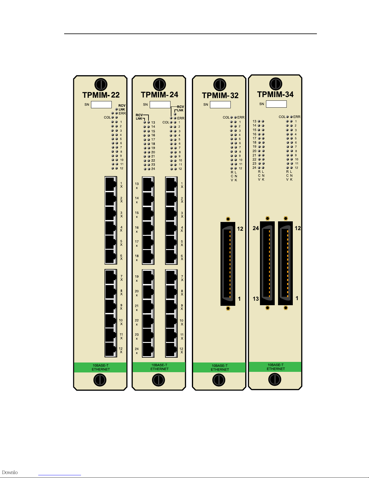
Cabletron Systems offers four versions of the 10BASE-T Twisted Pair Media Interface Module (Fig. 1-1) for connecting 10BASE-T Twisted Pair Segments to a
Multi Media Access Center (MMAC™):
• TPMIM-22 with 12 RJ-45 ports.
• TPMIM-24 with 24 RJ-45 ports.
• TPMIM-32 with one 50 pin Champ connector.
• TPMIM-34 with two 50 pin Champ connectors.
1.1 USING THIS MANUAL
10BASE-T Twisted Pair Media Interface
. We have designed this manual to
Chapter 1,
Cabletron Systems' TPMIM. This chapter also includes a list of related manuals.
Chapter 2,
requirements that must be met before installing the TPMIM. The specifications
for the TPMIM are also included in this section.
Chapter 3,
into the MMAC, connecting twisted pair segments to the MIM, and connecting
10BASE-T Ethernet devices to the TPMIM.
Introduction
Installation Requirements/Specifications,
Installing the TPMIM
, discusses the capabilities and special features of
, contains instructions for installing the TPMIM
contains a list of network
Page 1-1
INTRODUCTION
Figure 1-1. 10BASE-T Twisted Pair Media Interface Modules
Page 1-2

INTRODUCTION
Chapter 4,
Testing and Troubleshooting,
provides procedures for testing and
troubleshooting the installation of the TPMIM. Instructions for using LANVIEW®, Cabletron Systems’ built-in visual diagnostic and status monitoring sys-
tem, are also included.
We assume that you have a general working knowledge of Ethernet or IEEE 802.3
type data communications networks and their physical layer components.
1.2 GETTING HELP
If you need additional support related to the Cabletron Systems TPMIM, or if you
have any questions, comments or suggestions related to this manual, feel free to
contact Cabletron Systems' Technical Support at:
Cabletron Systems
35 Industrial Way
P.O. Box 5005
Rochester, NH 03867-5005
Phone: (603) 332-9400
1.3 THE 10BASE-T TWISTED PAIR MEDIA INTERFACE MODULES
Cabletron Systems' 10BASE-T Twisted Pair Media Interface Modules provide 12
or 24 ports, utilizing either RJ-45 ports or 50-pin Champ connectors. When used
with the MMAC-8/FNB™, up to 168 10BASE-T twisted pair segments can be
connected.
Distance and Cable Type
The TPMIM supports 10BASE-T Twisted Pair Segments up to 125 meters in
length. These segments can be made from a wide variety of popular unshielded
twisted pair cabling with properties varying from 75-165 ohm impedance and 2226 AWG conductor size.
Page 1-3

INTRODUCTION
Polarity Detection and Correction
Each Port on the TPMIM incorporates a Polarity Detection and Correction feature. The Polarity Detection and Correction feature allows the TPMIM to pass
data regardless of the polarity of the twisted pair segments’ receive link. If polarity is reversed, the LNK LED will flash to indicate this condition, once a good
packet passes through the port.
NOTE
: If this condition exists, the segment should be removed from the TPMIM
and the wiring corrected in the event that, in the future, the segment needs to be
attached to a device without the Polarity Correction and Detection feature.
Multi Media Access Centers
The Cabletron Systems’ 10BASE-T Twisted Pair Media Interface Modules are
designed to be installed into the Cabletron Systems MMAC. The modular design
of the MMAC allows the TPMIM to
co-exist with other Media Interface Modules (MIM™s) to provide a variety of different media connections on any one point. This means that the TPMIM can be
used by itself or in conjunction with any combination of other MIMs accommodating Fiber Optic Cable, Thick or Thin Ethernet Coaxial Cabling, or AUI Cabling.
Each packet entering the TPMIM is repeated by the MMAC’s repeater module.
These include the Cabletron Systems Intelligent Repeater Module (IRM-2™) and
Intelligent Repeater Bridging Module (IRBM™). Each packet that enters the repeater module is regenerated and retimed, which assures data integrity and maximum data path distance. In addition, the repeater feature ensures fault isolation,
since the repeater module will automatically segment problem ports from the network. A segmented port will be automatically reconnected to the network once
the port has received a good packet.
Page 1-4

INTRODUCTION
The repeater module also allows you to access the network management capabilities that enable you to control the TPMIM and its attached segments. For example, information on the number of good packets and collisions that have passed
through the TPMIM and each port on the MIM can be gathered. A variety of network management programs can be used to manage the TPMIM, including:
• Cabletron Systems SPECTRUM™.
• Cabletron Systems Remote LANVIEW/Windows™.
• Cabletron Systems Local Management.
• Third party SNMP compliant network management packages.
LANVIEW LEDs
The TPMIM incorporates LANVIEW, Cabletron Systems’ built-in diagnostic and
status monitoring LED system. These LEDs, incorporated into all Cabletron Systems’ products, will assist you in rapidly diagnosing network problems as they
arise. Each port on the TPMIM has two LANVIEW LEDs: the Link OK (LNK)
LED and the Receive (RCV) LED. The Link OK LED will remain lit as long as
a link is maintained between the applicable port on the module and the 10BASET device at the other end of the cable. If a link is not established, the LED will not
be lit. The Receive LED will be lit when activity is detected on the segment.
The TPMIM also has one Collision (CLN) LED, which indicates a collision on
any segment attached to one of the ports, and one Error (ERR) LED, which indicates a potential temperature problem within the MMAC.
1.3.1The TPMIM-22/24
The TPMIM-22/24 design incorporates built-in RJ-45 ports, 12 on the TPMIM22 and 24 on the TPMIM-24. This design makes it easier to incorporate twisted
pair wiring schemes into your network. The TPMIM-22/24 allows you to directly
connect the segments to patch panels or other 10BASE-T Ethernet devices, eliminating the need for Punch-Down blocks or additional patch panels.
Each RJ-45 port on the TPMIM-22/24 is internally crossed over, eliminating the
need to cross over the twisted pair segment going from the port to the 10BASE-T
device at the other end of the segment.
Page 1-5

INTRODUCTION
1.3.2The TPMIM-32/34
The TPMIM-32/34 provides an alternative method for incorporating 10BASE-T
twisted pair segments into an existing twisted pair wiring scheme. The TPMIM32 has one 50 pin Champ connector that allows you to connect 12 segments to the
module. The
TPMIM-34 has two 50 pin Champ connector that allows you to connect 24 segments to the module. The 50 Pin Champ connector allows the MIM to tie directly
into Punch-Down blocks and patch panels. This connector complies with all
punch down and harmonica specifications.
1.4 RELATED MANUALS
The manuals listed below should be used to supplement the procedures and other
technical data provided in this manual. The procedures in them will be referenced,
where appropriate, but will not be repeated.
Cabletron Systems’
5FNB and MMAC-8/FNB)
Cabletron Systems
Multi-Media Access Center (MMAC-3/FNB MMAC-
LAN-MD
Overview and Set Up Guide.
User Manual
.
Page 1-6

REQUIREMENTS/SPECS.
CHAPTER 2
INSTALLATION REQUIREMENTS/SPECIFICATIONS
Before you attempt to install the Cabletron Systems 10BASE-T Twisted Pair Media Interface Modules, review the network requirements that are outlined in this
chapter. Also, refer to the operating specifications that are listed.
All conditions, guidelines, specifications, and requirements included in this chapter must be met to ensure satisfactory performance of the TPMIM. Failure to follow these guidelines may result in unsatisfactory network performance.
2.1 NETWORK REQUIREMENTS
When connecting 10BASE-T twisted pair segments to the TPMIM, you must follow the network guidelines listed below.
•
Length
transceivers be able to transmit over a 100 meter
(328 feet) link using 24 AWG unshielded twisted pair wire.
10BASE-T specifies no maximum link length.
Due to cable delay, the maximum link length is always limited to about 200
meters (656 feet), regardless of the cable type.
As a general rule, links of up to 150 meters (492 feet) long are achievable for
unshielded and shielded twisted pair cable, with a maximum of 200 meters
(656 feet) due to cable delay. For each connector or patch panel in the link,
subtract 12 meters (39.4 feet) from the 150 meter limit. This will allow for
links of up to 126 meters (413.4 feet) using standard 24 AWG UTP wire and
two patch panels within the link. Higher quality low attenuation cables may
be required when using links greater than 126 meters.
- The IEEE 802.3 10BASE-T standard requires that 10BASE-T
Page 2-1
 Loading...