

Cabletron Systems SynOptics 3000, SynOptics 3030 Series Manual

SynOptics Series 3000 Hub
®
Management Module Guide

Notice
Cabletron Systems reserves the right to make changes in specifications and other information
contained in this document without prior notice. The reader should in all cases consult Cabletron
Systems to determine whether any such changes have been made.
The hardware, fi rmware, o r s o f tware de scribed in this man ual is subject to change with o ut notice.
IN NO EVENT SHALL CABLETRON SYSTEMS BE LIABLE FOR ANY INCIDENTAL,
INDIRECT, SPECIAL, OR CONSEQUENTIAL DAMAGES WHATSOEVER (INCLUDING BUT
NOT LIMITED TO LOST PROFITS) A RI SING OUT OF OR RELATED TO THIS MANUAL OR
THE INFORMATION CONTAINED IN IT, EVEN IF CABLETRON SYSTEMS HAS BEEN
ADVISED OF, KNOWN , OR SHOU L D H AVE KNOWN, THE POSSIBIL IT Y OF SUC H
DAMAGES.
Copyright © February 1998, by Cabletr on Syste ms, Inc. All rights reserved.
Printed in the United States of America.
Order Number: 9030920 E6
Cabletron Systems, Inc.
P.O. Box 5005
Rochester, NH 03866-5005
SPECTRUM, the SPECTRUM IMT/VNM logo, DCM, IMT , and VNM are regis t ered
trademarks, and Spectr oGRAP H, SpectroSERVER, Inductive Modeling Technology,
Device Communications Manager, and Virt ua l Netwo rk Machine are trademarks of
Cabletron Systems, Inc.
C++ is a trademark of American Telephone and Telegraph, Inc.
UNIX is a trademark of The Open Group.
OSF/Motif and Motif are trademarks of the Open Software Foundation, Inc.
X Window System is a trademark of The Open Group.
Ethernet is a trademark of Xerox Co rpora tion.
9030920 E6
i

Virus Disclaimer
Cabletron Systems makes no representations or warranties to the effect that the Licensed
Software is virus-free.
Cabletron has tested its software with cur re n t virus checking technologies. Howeve r, because no
anti-virus system is 100% rel iable, we str o ngl y cau tio n you to wri te prot ect and then verify that
the Licensed Sof tw a re, prio r to installing it, is virus-free with a n anti -v iru s sys te m in whic h you
have confiden ce.
Restricted Rights Notice
(Applicable to licenses to the United States Go ver nm e nt only.)
1. Use, duplication , or disc losur e by the Gov ern m en t is sub je ct to restr ict io ns as se t forth in
subparagraph (c) (1) (ii) of the Rights in Technical Data and Computer Software clause at
DFARS 252.227-7013.
Cabletron Systems, Inc., 35 Industrial Way, Rochester, New Hampshire 03866-5005.
2. (a) This computer software is submitted with restricted rights. It may not be used,
reproduced, or disclosed by the Government except as provided in paragraph (b) of this
Notice or as otherwise expressly stat ed in the contra ct.
(b) This computer software may be:
(1) Used or copied for use in or with the computer or computers for which it was
acquired, inclu ding use at any Government in stallation to which such compu ter or
computers may be transferred;
(2) Used or copied for use in a backup computer if any computer for which it was
acquired is inoperative;
(3) Reproduced for safekeeping (archives) or backup purposes;
(4) Modified, adapted, or combined with other computer software, provided that the
modified, combined, or adapted portions of the derivat ive so ftware incor porati ng
restricted computer software are made subject to the same restricted rights;
(5) Disclosed to and reproduced for use by support service contractors in accordance with
subparagraphs (b) (1) through (4) of this clause, provided the Government makes
such disclosure or reproduction subject to these restricted rights; and
(6) Used or copied for use in or transferred to a replacement computer.
(c) Notwithstanding the foregoing, if this computer software is published copyrighted
computer software, it is licensed to the Government, without disclosure prohibitions, with
the minimum rights set f o rt h in paragrap h (b) of this cl a use.
(d) Any other righ ts or lim itations regarding the use , dupli cati on , or disc lo sur e of this
computer software are to be expressly stated in, or incorporated in, the contract.
(e) This Notice shall be marked on any reproduction of this computer software, in whole or in part.
SynOptics Series 3000 Hub
ii Management Module Guide

Preface
What is in this Guide............................................................................................................ xi
Terminology..........................................................................................................................xii
Conventions ........................................................................................................................xiii
Related SPECTRUM Docu ment a t ion.......... ................. ....................... ........................ ......xiii
Other Related Documentation........................................................................................... xiv
Chapter 1 Introduction
What is in this Chapter......................................................................................................1-1
SynOptics 3000 Series Hub s..............................................................................................1-1
SPECTRUM Model Type....................................................................................................1-1
Supported Mibs............................... ........................ ....................... ........................ .............1-5
Accessing SPECTRUM Views............................................................................................1-6
Roadmap of SPECTRUM Views ........................................................................................1-8
Chapt er 2 Devic e Vi ew
Contents
What is in this Chapter......................................................................................................2-1
Logical Device View............................................................................................................2-1
Ethernet Module Icon..................................................................................................2-3
Module Identification Labels................................................................................2-3
Module Icon Subviews Menu Selections...............................................................2-4
Port Icon.................................................................................................................2-4
Port Icon Subviews Menu Selections ....................................................................2-4
Token Ring Module Icon ..............................................................................................2-5
Module Identification Labels................................................................................2-6
Module Icon Subviews Menu Selections...............................................................2-6
Port Icons ...............................................................................................................2-7
Port Icon Subviews Menu Selections ....................................................................2-7
FDDI Module Icon........................................................................................................2-8
Module Identification Labels................................................................................2-8
Module Icon Subviews Menu Selections...............................................................2-9
Port Icon.................................................................................................................2-9
Port Icon Subviews Menu Selections ..................................................................2-10
Physical Device View ........................................................................................................2-10
9030920 E6
iii

Chapter 2 Device View (cont inu e d)
Bridge Device View ...........................................................................................................2-12
Bridge Interface Icon..................................................................................................2-13
Interface Number Label.......................................................................................2-14
Administrative Status Label...............................................................................2-14
Port Type Label....................................................................................................2-14
MAC Address Label .............................................................................................2-15
Network Information Label.................................................................................2-15
Gauge Label..........................................................................................................2-15
Interface Options Panel..............................................................................................2-16
Gauge Control Panel..................................................................................................2-16
Chapter 3 Configuration Views
What is in this Chapter ......................................................................................................3-1
NMM Nodes.........................................................................................................................3-2
SynOptics Token Ring Show Nodes Table View..........................................................3-2
SynOptics Token Ring Find Nodes Table View...........................................................3-3
Ethernet Configuration ......................................................................................................3-4
SynOptics Ethernet Frames and Errors View............................................................3-4
SynOptics Ethernet Frame Sizes and Protocols View................................................3-5
SynOptics Ethernet NMM Table View........................................................................3-5
SynOptics Ethernet Host Table View..........................................................................3-5
SynOptics Ethernet Threshold Table View.................................................................3-6
Add Threshold....... ................ ........................ ........................ ....................... ........3-10
Token Ring Configuration.................................................................................................3-11
SynOptics Token Ring Station Table View................................................................3-11
SynOptics Token Ring Total Errors Table View........................................................3-12
SynOptics Token Ring Station Isolating Errors View..............................................3-12
SynOptics Token Ring Station Non-Isolating Errors View......................................3-13
SynOptics Token Ring NMM Topology Table View...................................................3-14
SynOptics Token Ring NMM Configuration View....................................................3-14
FDDI Configuration..........................................................................................................3-15
SynOptics FDDI NMM Ring Status View.................................................................3-15
SynOptics FDDI NMM Station Worst Errors View..................................................3-16
SynOptics FDDI NMM SRF Event Counters View..................................................3-16
SynOptics FDDI NMM SRF Condition View............................................................3-17
SynOptics FDDI NMM Ring Topology View.............................................................3-17
SynOptics Physical Topology Trunk View.................................................................3-18
SynOptics Physical Topology Node View...................................................................3-18
SynOptics NMM Optical Bypass Switch View..........................................................3-19
Device Config u ra t ion .... ................. ....................... ........................ ........................ ............3-20
SynOptics Configuration View ...................................................................................3-20
SynOptics Agent Download View ..............................................................................3-20
Current Info rma tion ......................... ........................ ........................ ...................3-21
Next Boot..............................................................................................................3-21
SynOptics Agent Protocol Configuration View.........................................................3-22
SynOptics Agent Configuration View ........................................................................3-24
SynOptics Agent Hardware View..............................................................................3-25
SynOptics IP Trap Receiver View..............................................................................3-26
SynOptics IPX Trap Receiver View ...........................................................................3-27
SynOptics Series 3000 Hub
iv Management Module Guide

Chapter 3 Configuration Views (continued)
SynOptics Chassis Configuration View...........................................................................3-27
Module Configuration Table......................................................................................3-28
SynOptics Module Configuration View ..............................................................3-29
SynOptics Redundant Power Supply View...............................................................3-30
SynOptics Ethernet Local Bridge Configuration View...................................................3-31
SynOptics Ethernet Local Bridge Range Table ........................................................3-32
SynOptics Ethernet Local Bridge Spanning Tree Configuration............................3-33
Spanning Tree Port Data......... ........................ ....................... ........................ ....3-34
SynOptics Ethernet Local Bridge Filter Table .........................................................3-34
Chapter 4 Event and Alarm Messages
What is in this Chapter......................................................................................................4-1
SynOptics Series 3000 Events and Alarms.......................................................................4-1
Chapter 5 Application View
What is in this Chapter......................................................................................................5-1
Syn3 Common /Syn3FDDI/Syn3Stck Application............................................................5-2
Syn3EnetBdg Applic a tion.......................... ....................... ........................ ........................ .5-2
SynTR Applicati o n..... ....................... ........................ ........................ ....................... ...........5-2
Syn3FDDISMT Appl ica tion................................... ....................... ........................ .............5-3
SynOptics FDDI SMT Configuration View.................................................................5-3
SynOptics FDDI SMT Parameters View ....................................................................5-4
SynOptics FDDI SMT LER Thresholds Table View...................................................5-5
SynFDDIMAC Application............... ........................ ........................ ....................... ...........5-6
SynOptics FDDI MAC Configuration View................................................................5-6
SynOptics FDDI MAC Parameters View....................................................................5-7
SynOptics FDDI MAC Performance View..................................................................5-8
SynOptics FDDI MAC Detail View.............................................................................5-8
SynOptics FDDI MAC Station Table View.................................................................5-9
9030920 E6
v

SynOptics Series 3000 Hub
vi Management Module Guide

Figures
Chapter 1 Introduction
Figure 1-1. Using Double-Click Zones to Access SPECTRUM Views ...................................1-6
Figure 1-2. Accessing Icon Subviews Menus from the Device Icon .......................................1-7
Figure 1-3. Accessing Icon Subviews Menus from Labels .....................................................1-7
Figure 1-4. SPECTRUM Views Roadmap ..............................................................................1-8
Chapt er 2 Devic e Vi ew
Figure 2-1. Logical Device View ..............................................................................................2-2
Figure 2-2. Ethernet Module Icon ...........................................................................................2-3
Figure 2-3. Token Ring Module Icon .......................................................................................2-5
Figure 2-4. FDDI Module Icon ................................................................................................2-8
Figure 2-5. Physical Device View .......................................................................................... 2-11
Figure 2-6. Bridge Device View .............................................................................................2-12
Figure 2-7. Interface Icon ......................................................................................................2-13
Figure 2-8. Gauge Control Panel ..........................................................................................2-17
9030920 E6
vii

SynOptics Series 3000 Hub
viii Management Module Guide

Tables
Chapter 1 Introduction
Table 1 -1. Supported Ethernet Model Types.........................................................................1-2
Table 1 -2. Supported Token Ring Model Types.....................................................................1-3
Table 1 -3. Supported FDDI Model Types..............................................................................1-4
Table 1 -4. Supported Bridge Model Types.............................................................................1-5
Table 1-5. Supported MIBs............ ........................ ....................... ........................ ..................1-5
Chapt er 2 Devic e Vi ew
Table 2 -1. Module Icon Subviews Menu ...............................................................................2-4
Table 2 -2. Ethernet Port Menu Selections.............................................................................2-5
Table 2 -3. Module Icon Subviews Menu ...............................................................................2-6
Table 2 -4. Token Ring Port Menu Selections........................................................................2-7
Table 2 -5. Module Icon Subviews Menu ...............................................................................2-9
Table 2 -6. FDDI Port Menu Selections................................................................................2-10
Table 2 -7. Administrative Status for the Physical Application ..........................................2-14
Table 2 -8. Administrative Status for the Bridging Application .........................................2-14
Table 2 -9. Rate Gauge Mode: Attributes and Corresponding Color...................................2-18
Table 2 -10. Totals Gauge Mode: Attributes and Corresponding Color................................2-18
Chapter 3 Configuration Views
Table 3-1. Threshold Co ndi t i o n............... ....................... ........................ ........................ ........3-8
Chapter 4 Event and Alarm Messages
Table 4 -1. SynOptics Series 3000 Events and Alarms..........................................................4-1
9030920 E6
ix

SynOptics Series 3000 Hub
x Management Module Guide

Use this guide if you are goin g to ma nage any SynOptics 3000 Series H ub
through SPE CTRUM. Before reading this gu ide , you sh o uld be famili ar with
SPECTRUM’s functions. You should also be familiar with any network
management and hardware requirements described in the related SynOptics
hub documentation.
What is in th is G u ide
The following chapter descriptions outline the organization of the SynOptics
3000 Series Management Module Guide:
Chapter Description
Preface
Chapter 1
Introduction
Chapter 2
Device View
Chapter 3
Configuration Views
Chapter 4
Configuration Views
Chapter 5
Application View
Describes the Sy nOptics hub
management module and model types.
Describes the Dev ice View’s logical and
physical representation of a SynOptics
hub.
Describes the Conf ig ur atio n Views for
the SynOptics 3000 Series hub mo dels ,
which provid e network manageme n t
information for the device.
Contains a listing and explanation of the
event/alarm mess age s generated in the
Event Log and Alarm View for the
SynOptics hub model types.
Describes the Applic atio n View for the
SynOptics 3000 Series hub mo dels and
the major and minor applicat io n
information provided by the view.
9030920 E6
xi

Terminology
Terminology
This section defines several terms used in this guide to describe the SynOptics
hub model types.
Hub
For the purposes of this guide, the general term hub replaces the term
conce ntrator in representing SynOptics devices.
Hub Chassis
The software model represen tati on of the SynOptic s hub (4 or 12 slots) with
no modules inst alle d in any of its slots.
Media Interface Modules
The software model representations of modules installed in a SynOptics hub
chassis. Ther e are tw o ty pes of Mo dule s: Inte llige n t M odu le s and N o nIntelligent Modules.
Intelligen t Mod ules
Modules that provide network management functions and network media
interfacing. These are also referred to as NMM - network management
modules.
Non-intelligent Modules
Modules that provide i nterfaces to different ki n ds of netw ork media, but have
no network management capabilities.
Refer to the specific Syn Op tic s har dware manual for a detailed description of
your particular SynOptics hub or module.
Preface SynOptics Series 3000 Hub
xii Management Module Guide

Conventions
This guide uses the following conventions:
• Menu select ions and buttons refer e nced in text appear in bold; for
example, Configuration or Detail.
• Button names ap p ear in sh ado wed boxes when in trod ucing paragraphs
describing their use; for example:
Help
• Menu navigation appears in order of selection ; for exampl e, Icon
Subviews -> Utilities -> Appl ic ation.
• Referenced chapter titles and section headings appear in italics.
• Referenced documents appear in bold italics.
• Hypertext links are blue f or online documents.
• SynOptics 3000 Series Hub is referred to as “device.”
Conventions
Related SPECTRUM Documentation
Refer to the followin g d ocum e n tatio n for mo re inf o rmation on managing with
SPECTRUM:
Routing Services Management Module Guide
Report Generator User’s Guide
Getting Started With SPECTRUM for Operators
Getting Started With SPECTRUM for Administrators
How To Manage Your Network With SPECTRUM
9030920 E6 Preface
xiii

Other Rela t ed Doc um e nt a tio n
Other Related Documentation
Refer to the followin g d ocum e n tatio n for mo re inf o rmation on managing
TCP/IP-based networks:
Martin, James, Kathleen Kavanagh Chapman, Joe Leben. Local Area
Networks: Architectures and Implementations, 2d ed. Englewood Cliffs,
NJ: Prentice Hall, 1994.
Rose, Marshall T. The Simple Book: An Introduction to Management of
TCP/IP-based Internets. Englewood Cliffs, NJ: Prentice Hall, 1991.
Stallings, William. Data and Computer Communications, 4th ed. New
York: Macmillan Publishing C om pany, 1994.
Tanenbaum, Andrew S. Computer Networks, 3d ed. Englewood Cliffs, NJ:
Prentice Hall, 1996.
Preface SynOptics Series 3000 Hub
xiv Management Module Guide

Introduction
What is in th is C h apter
This chapter introd uc es the SP EC T RU M Management Module for Syn Op tic s
Model 3000 Series hubs. It describes the following:
• SynOptics 3000 Se r ies Hub s
• SPECTRUM Model Type
• Accessing SPECTRUM Views
• Roadmap of SPECTRUM Views
Chapter 1
SynOptics 3000 Series Hubs
The SynOptics 3000 Series Hubs are 12 (3000) and 4 (3030) slot concentrators.
Table 1-1through Table 1-4 list the modules based on technology that are
installed in the concentrators above.
SPECTRUM Model Type
The model type refers to the management module software package used to
specify attributes, actions, and associations for the physical device using the
Simple Network Management Protoc ol (SNMP) and Management Information
Bases (MIBs). The fo llowing section details t he di fferent model types provided
by this management module, and describes the supported physical modules
corresponding to each model type.
9030920 E6
1-1

SPECTRUM Model Type
HubSynSer3xxx
This model type represents the SynOptics Model 3000 Ethernet hub series of
devices. Table 1-1 provides a list of supported Ethernet models and their
descriptions.
Table 1-1. Supported Ethernet Model Types
Model Description
3040 Network control engine (Sparc)
3040s Network control engine (Sparc)
3100r Summing module
3174 Work station Controll er
3301 Ethernet ThinNet hos t module
3301_75 Thin net ether host module
3301_93 Thin net ether host module
3302 Shielded twisted p air ether host module
3304a 10BASE-F host module
3304st Ether fiber host module
3305 UTP Ethernet host module
3307 UTP Ethernet 50 pin host module
3307a Ether host modul e wi th am p
3307hd UTP Ethernet 50 pin host module
3308 Ether host modul e
3308a Ether host modul e
3308b 10BASE-T Ethernet host module
3313 Ether AUI NMM with RS232 port
3313a Ether AUI NMM with RS232 port
3313m Ether AUI NMM with modem
3313s Ether AUI NMM with modem
3313sa Ethernet NMM (sup er ag ent)
3314a Ether FOIRL NMM w/RS232 port
3314s Ether FOIRL NMM with modem
3314sa Ethernet FOIRL NMM (sup er agent)
3314st Ether FOIRL NMM w/RS232 port
Introduction SynOptics Series 3000 Hub
1-2 Management Module Guide

Table 1-1. Supported Ethernet Model Types (Continued)
Model Description
3314mst Ether FOIRL NMM with modem
331x Ether NMM w/unknown MDA type
3323 Ether AUI local bridg e
3328 Ethernet Switching Engi ne
3333 Ethernet AUI retiming module
3334st Ethernet FOIRL retiming module
3356 Ether remote brid g e
3368 10BASE-T Ethernet host module
3383 Ether AUI local router
3384 Ether FOIRL local router
3386 cisco remot e router
SPEC T RUM Model Type
3394 Ether-l ocaltalk router
3395 Xyplex terminal server
3395a Xyplex terminal server
HubSynTR3xxx
This model type represents the SynOptics Model 3000 Token Ring hub series
of devices. Tab le 1- 2 provides a list of supported Token Ring models and their
descriptions.
Table 1-2. Supported Token Ring Model Types
Model Description
3100r Summing module
3502 STP Token Ring host module
3502a STP Token Ring host module
3502b STP/UTP Token Ring host module
3504-st Fiber Token Ring host module
3505 UTP Token Ring host module
3505a UTP Token Ring host module
3505b UTP/STP Token Ring host module
3512 TR NMM w/STP ring in/ ring out
9030920 E6 Introduction
1-3

SPECTRUM Model Type
Table 1-2. Supported Token Ring Model Types (Continued)
Model Description
3512s TR NMM w/STP ring in/ring out
3513 STP Token Ring NMM
3513s STP TR repeater NMM
3513sa Token Ring NMM (super agent )
3514st Fiber Token Ring NMM
3514s TR NMM w/FOIRL ring in/ring out
3517sa Fiber/STP Token Ring NMM (super agent)
351x TR NMM module w/unkno wn MDA type
3522 STP Token Ring Local Bridge
3522a TR Local Bridge
3532 STP Token Ring ring in/ring out module
3534 FOIRL repeater
3552 STP ring in/ring out module
3554 FOIRL ring in/ring out module
HubSyn3FDDI
This model type represents the SynOptics FDDI 3000 series of devices. Table
1-3 provides a list of supported FDDI models and their descriptions.
T abl e 1-3. Supported FDDI Model Types
Model Descripti on
3904 Multi-mode Fiber FDDI Host module
3904-2sm Single-mode Fiber FDDI Host module
3905 UTP FDDI Host module
3910s Multi-mode Fiber FDDI NMM
3910s-sm Single-mode Fiber FDDI NMM
BdgSyn332xS
This model type represents the SynOptics 332xS Ethernet Local Bridge. The
bridge module in the 3000 Series hub does not recognize the rest of the hub,
therefore any Hub Chassis views are not available. Table Table 1-4 provides a
list of supported Bridge models and their descriptions.
Introduction SynOptics Series 3000 Hub
1-4 Management Module Guide

Table 1-4. Supported Bridge Model Types
Model Description
3323s Ethernet AUI high speed local bridge
3324-st Ethernet FOIRL high speed local bridge
Supported Mibs
The SynOptics Series 3000 Management Module supports four types of
models to represe nt both the physical hub and its interface s. The fo llo win g
sections provide a description of these models and how they are related. Table
1-5 lists the supported MI Bs.
Table 1-5. Supported MIBs
Supported Mibs
MIB Release Number Imports From
SynOptics Common 4.2.0 RFC1155- SMI
RFC1213-MIB
RFC-1212
SynOptics Ethernet 4.1 RFC-1213-MIB
RFC-1155-SMI
RFC-1212
SynOptics Basic
Ethernet & Token
Ring 2K & 3K
SynOptics Token
Ring
SynOptics FDDI
Concentrator
SynOptics Ethernet
Local Bridge
N/A RFC1155-SMI
RFC-1212
RFC-1215
4.0.2 RFC1155-SMI
RFC-1212
RFC1213-MIB
SynOptics-Common-MIB
2.1.2 RFC1155-SMI
RFC-1212
RFC1213-MIB
SynOptics-Common-MIB
N/A RFC1065-SMI
9030920 E6 Introduction
1-5
Access in g S PEC TRUM Views
Accessing SPECTRUM Views
Icons provide access to SPECTRUM views that display device-speci fic
information. Access these views through double-click zones (Figure 1-1) and
Icon Subviews men us (Figure 1-2 and Figure 1-3).
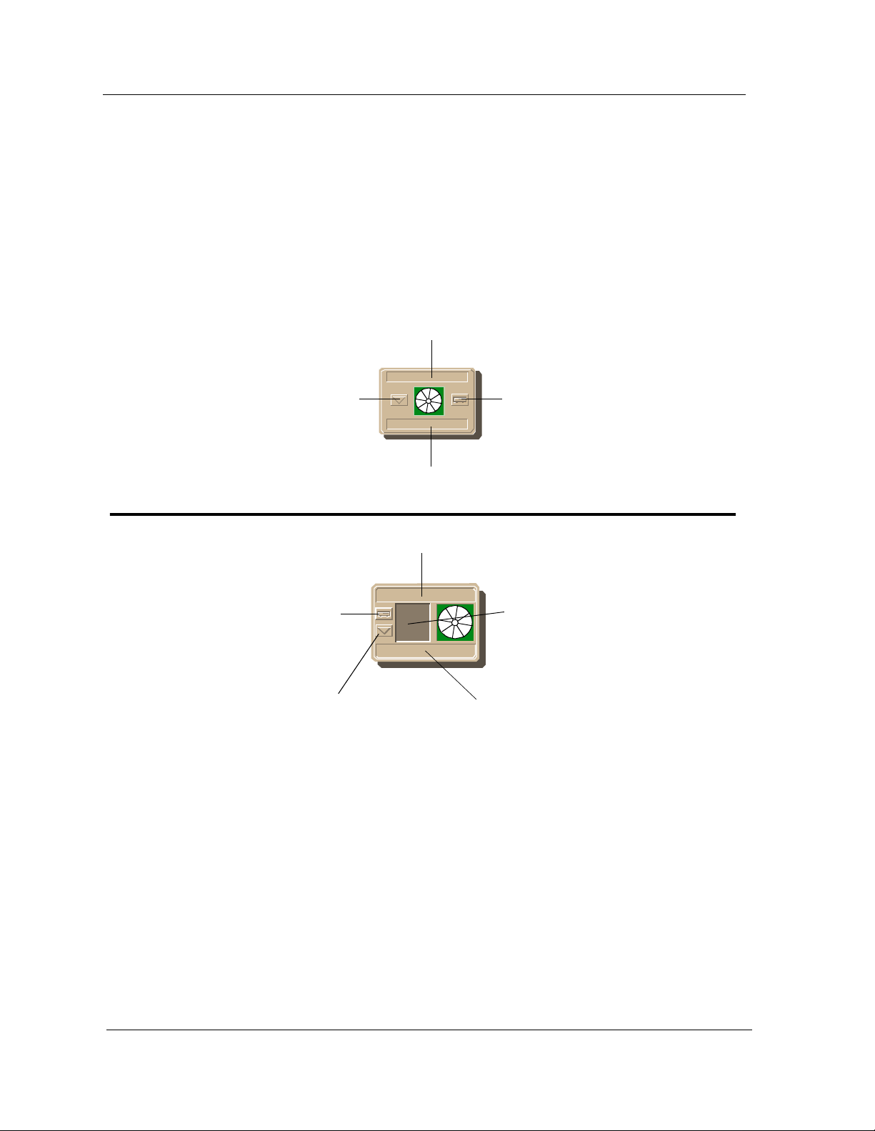
Figure 1-1. Using Double-Click Zones to Access SPECTRUM V iews
Accesses the Co nfiguration view; see
Chapter 3, Configuration Views.
Accesses the De vic e Topology view;
refer to SPECTRUM Views.
Accesses the Ap plication view; see
Chapter 5, Application View.
Accesses the Configuration view; see
Chapter 3, Configuration Views.
Accesses a Device view; see
Chapter 2, De vice View.
Accesses th e Dev ice Topology view;
refer to the SPECTR UM Views.
Model Name
Hub_SynSer3xxx
Model Name
Hub_SynSer3xxx
Accesses a Device view; see
Chapter 2, Device View.
Accesses the Performance view;
refer to the SPECTRUM Views.
Accesses the Application view; see
Chapter 5, Application View.
Introduction SynOptics Series 3000 Hub
1-6 Management Module Guide
Access i ng S P E C TR U M Views
To access the Icon Subviews menu as shown in Figure 1-2 and Figure 1-3, do
the following:
1. Highlight the icon or label.
2. From the View menu, select Icon Subviews, or click and hold the
applicable mouse button (middl e or rig ht) ove r the icon or label. Refer to
the Icons documentation for information on configuring your mouse.
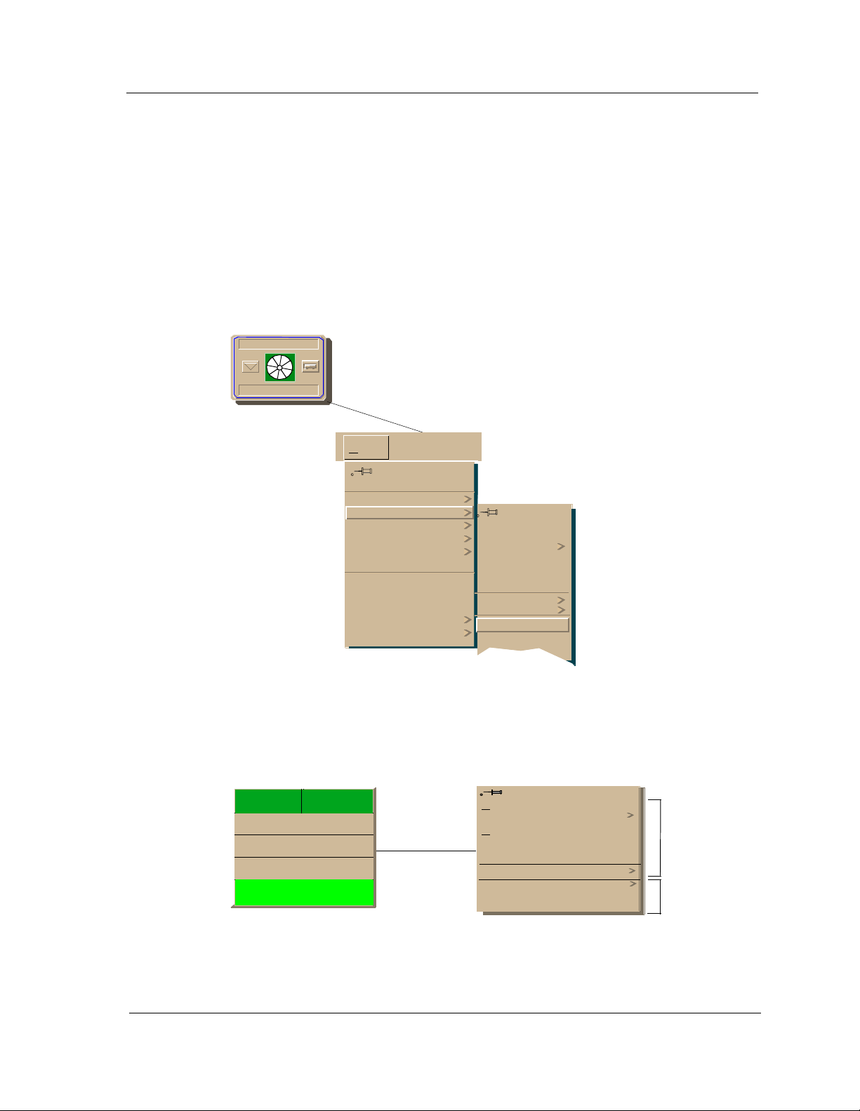
Figure 1-2. Accessing Icon Subviews Menus from the Device Icon
Model Name
Hub_SynSer3xxx
View
Go Back
Go Up
Icon Subviews
View Path
New View
Bookmarks
View Hist ory
Current View Info...
Notes...
Jump by name...
Zoom
Map Hierarchy
Ctrl+b
Close
Navigate
Alarms
Performance
Notes...
Utilities
Zoom
Device
DevTop
Ctrl+c
Figure 1-3. Accessing Icon Subviews Menus from Labels
t1
ISO88025
0:0:1D:52:CF:F2
ON
0
Close Ctrl + c
Navigate
A
larms
Performance
Notes...
Utilities
Configuration
Model Information
Common
Device-Specific
9030920 E6 Introduction
1-7
Roadmap of SPECTRUM Views
Roadmap of SPECTRUM Views
Figure 1-4 shows a “roadmap” of the SPECTRUM views for this dev i ce. These
views are accessible from double-click zones (Figure 1-1) and Icon Subviews
menus (Figure 1-2 and Figure 1-3).
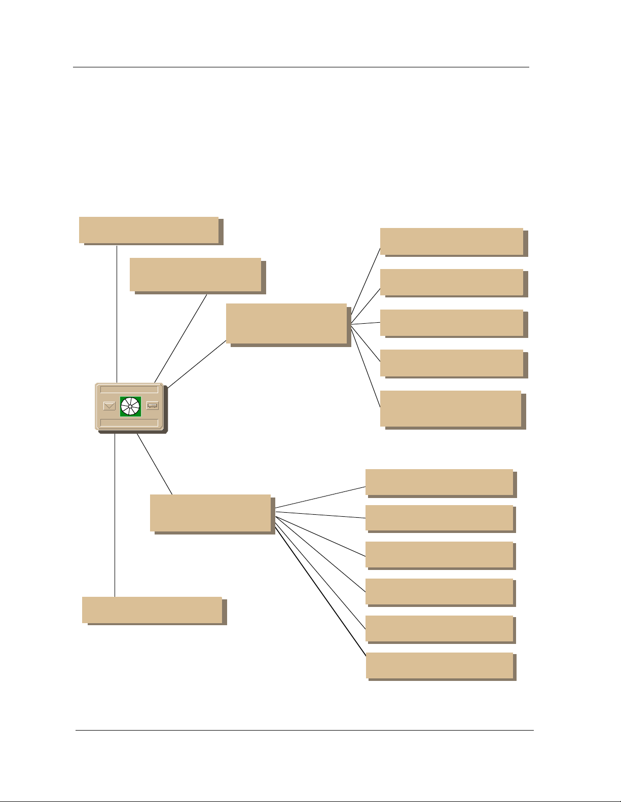
Figure 1-4. SPECTRUM Views Roadmap
Pe rformance vie w; refer to the
SPECTRUM Views.
Device view ; see Chapter 2,
Device View.
Configuration vie w; see
Chapter 3,
Confi gur ati on
Views.
Device Configu rat ion view
Ethernet Configuration view
TR Configuration view
Model Name
Hub_SynSer3xxx
Application view; see
Chapter 5,
DevTop view; refer to the
SPECTRUM Views.
Application
View.
FDDI Configuration view
Ethernet Bridge
Configur atio n vie w
SynOptics 3000 Common
Application
SynOptics 3000 FDDI
Application
SynOptics 3000 Ethernet
Bridge Application
SynOptics 3000 Token Ring
Application
SynOptics 3000 FDDI SMT
Application
SynOptics 3000 FDDI MAC
Application
Introduction SynOptics Series 3000 Hub
1-8 Management Module Guide

Device View
NOTE
What is in th is C h apter
This chapter desc ribes th e fo llowing Device views available for the S ynO p tic s
3000 Series Hubs management module:
• Logical Device View
• Physical Device View
• Bridge Device View
Chapter 2
See Chapter 1, Introduction, for information on Accessing SPECTRUM Views.
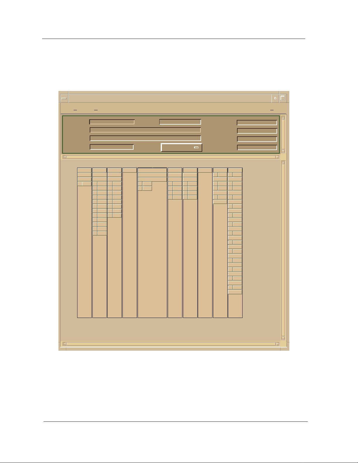
Logical Device View
This view displays a logical representation of the modules installed in the
hub. The logical module representation provides information about the
individual modules and its ports. Figure 2-1 show examples of a Logical
Device view with module for Ethernet, Token Ring, and FDDI hubs. I f the
configuration cha nges (for example, a module is pulled or added to the hub),
you see the corr e sp o nding change within this De vic e vie w afte r the ne xt
SPECTRUM polling cycle for the hub.
The SynOptics 332xS Ethernet Local Bridge will not have a Logical Device
View. The hub representation is not a true reflection of a Logical Device in
that the modules are of di fferent technologies (Ether net, FDDI, etc.). In your
view the hub will show on ly th os e mod ules for a technology-specific hu b.
9032209 E1
2-1
Logical Device View
Figure 2-1. Logical Device View
Example of type HubSyn3xxx of Landscape daedalus: P ri m ary
*
File View Help?
Model Name
Contact
Description
Locati on
33145
1
1 111098765432
ON
NLNK
10
11
12
3308
ON
NLNK
1
NLNK
2
NLNK
3
4 ON
NLNK
5
NLNK
6
NLNK
7
NLNK
8
NLNK
9
NLNK
NLNK
NLNK
3301
ON
1 ON
2 ON
3 ON
4 ON
5 ON
6 ON
7 ON
8 ON
Net Addr
Prime-App
5
3910S
Enable
1
Enable
2
Sys Up Time
Manufa ct ur er
Device Type
Serial Number
10 ON
39053902A
Enable
Enable
Enable
Enable
Enable
1
Enable
2
Enable
3
Enable
4
1
2
3
4
33145
R1 16M
1 Ring
BYP
2 Ring
BYP
11 ON
3301
R1 16M
1 Sta
ON
2 Sta
ON
3 Sta
ON
4 Sta
ON
5 Sta
ON
6 Sta
BYP
7 Sta
BYP
8 Sta
BYP
9 Sta
BYP
10 Sta
BYP
11 Sta
BYP
12 Sta
BYP
Token Ring Sma r tS wit ch M o dule
2-2 Management Module Guide
Ethernet Module Icon
This icon is a logical representation of the phy sica l mod ule. It shows the
location in the hub chassis and its front panel interfaces and ports. Figure 2-2
shows an example of an Ethernet Module icon.
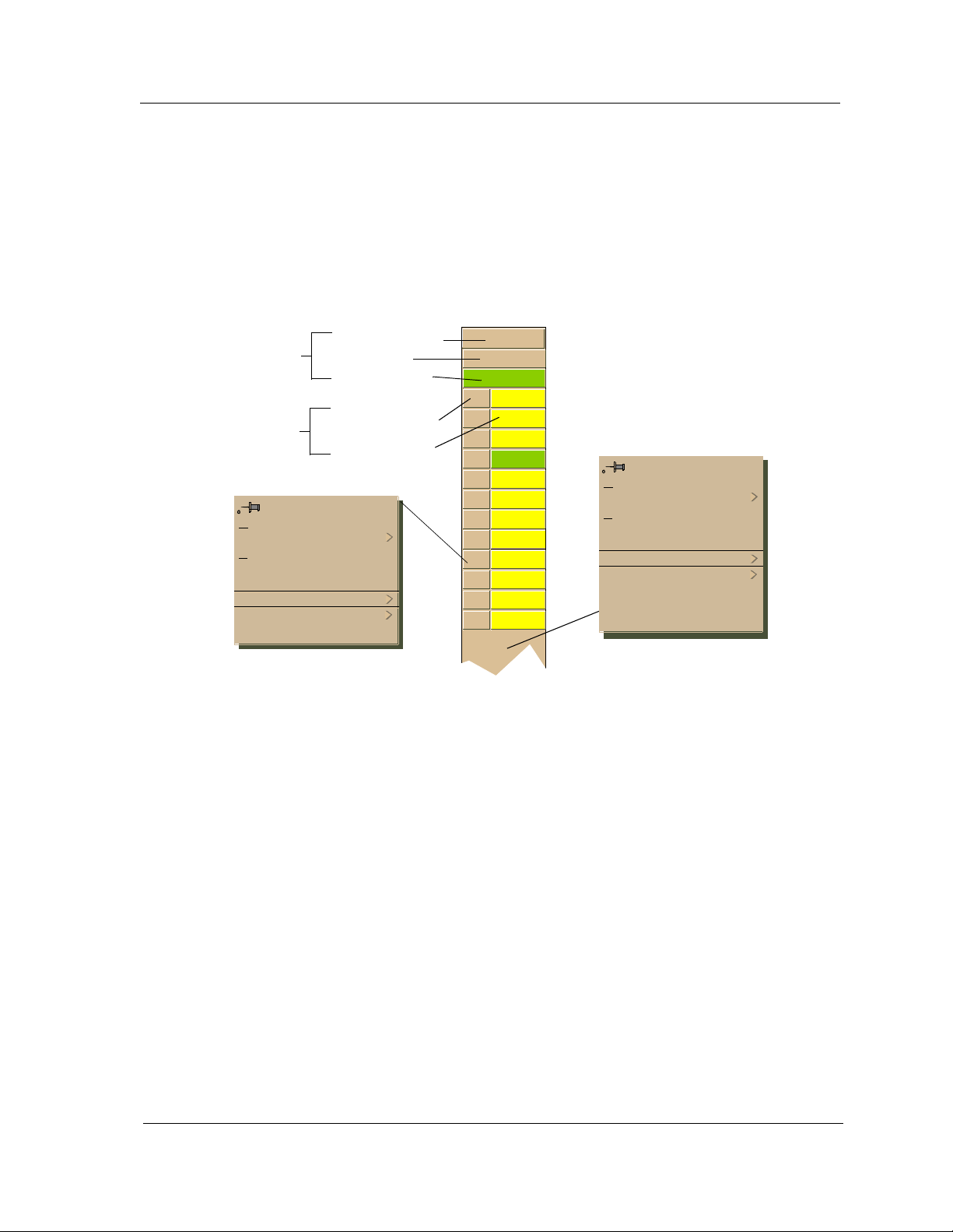
Figure 2-2. Ethernet Module Icon
Logical Device View
Module
Identification
Labels
Port Icons
Close Alt+F4
Navigate
A
larms
Perfor mance
Notes...
Utilities
Port Notes
Port Performance
Module Number
Model Type
Module Status
Port Number Label
Port Status Label
Module Identification Labels
2
3308
ON
1 NLNK
2 NLNK
3 NLNK
4 ON
5
NLNK
6 NLNK
7 NLNK
8 NLNK
9 NLNK
10 NLNK
11 NLNK
12 NLNK
Close Alt+F4
Navigate
A
larms
Performance
Notes...
Utilities
Module Notes
Module Port Table
Module Configuration
Module Performa nce
9032209 E1
These labels provide the following information:
Module Number
Identifies the number of the module in the hub. Double-click this label to
access the Mod ul e N ote s.
Module Type
Identifies the type o f mod ule that occupies this slot in the hub. Do uble- cl ick
this label to access the Model Information view described in the SPECTRUM
Views.
Module Status
Identifies the sta tus of the module. Double-click this labe l to access th e
performance view. Performance views are described in the SPECTRUM
Views. Module status cond itions are defined as follows:
• ON - Green
• PAR (Partitioned) - Yellow
2-3

Logical Device View
Module Icon Subviews Menu Selections
Table 2-1 lists each of the device-specific Icon Subviews menu selections
available for this device. See Chap ter 1, Introduction, for information on
Access in g S PEC TRUM Views.
T able 2-1. Module Ico n Subv i ew s Menu
Menu Select io n Description
Module Notes Opens the Module Notes view which allows you to keep
notes specific to this module .
Module Port Table Opens the Port Table view.
Module Configuration Opens the Ethernet Configuration view described in
Chapter 3, Configuration Views.
Module Performa nce Opens the Performance v i ew des cribed in the
SPECTRUM Views.
Port Icon
Port icons display the f ollo wing information for each p o rt on the d ev ice:
Port Type Label
Ide ntifi es whi c h por t this icon r e pres e nts. Double-cli ck th is label to access the
Port Notes view.
Port Status Label
Displays the status of the port. Double-click this label to open the Port
Performance view. Port status conditions are defined as follows:
• NLNK (No Link) - Yellow
• ON - Green
• OFF - Blue
Port Icon Subviews Menu Selections
Table 2-2 lists each of the port-specif ic Icon Subviews menu select io ns
available for this device. See Chap ter 1, Introduction, for information on
Access in g S PEC TRUM Views.
Token Ring Sma r tS wit ch M o dule
2-4 Management Module Guide
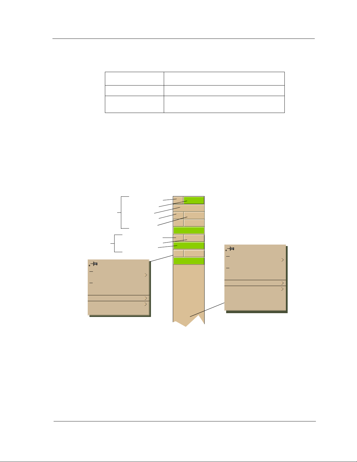
Table 2-2. Ethernet Port Menu Selections
Menu Selection Description
Port Notes Opens the Port Notes view.
Port Performance Opens the Port Performance view described in
the
SPECTRUM Views.
Token Ring Module Ico n
This icon is a logical representation of the phy sica l mod ule. It shows the
location in the hub chassis and its front panel interfaces and ports. Figure 2-3
shows an example of a Token Ring Module icon.
Figure 2-3. Token Ring Module Icon
Logical Device View
Module
Identification
Labels
Port Icons
Close Alt+F4
Navigate
A
larms
Performance
Notes...
Utilities
Port Notes
Port Performance
Module Number
Module Status
Model Ty pe
Ring Number
Module Speed
Port Number Label
Port Type Label
Port Status Label
3 ON
3505
R1 16M
1 Sta
ON
2 Sta
ON
3 Sta
ON
Close Alt+F4
Navigate
A
larms
Performance
Notes...
Utilities
Module Notes
Module Port Table
Module Configuration
Module Performa nce
9032209 E1
2-5

Logical Device View
Module Identification Labels
These labels provide the following information:
Module Number
Identifies the slot number of the module in the hub. Double-click this label to
access the Mod ul e N ote s.
Model Type
Identifies the mo d el typ e for this device.
Module Status
Identifies the operating status of the module. Double - c lick this label to access
the Module Performance view described in the SPECTRUM Views.
Ring Number
Identifies which ring this module is on.
Module Speed
Identifies the transmission speed setting of the module.
Module Icon Subviews Menu Selections
Table 2-3 lists each of the device-specific Icon Subviews menu selections
available for this device. See Chap ter 1, Introduction, for information on
Access in g S PEC TRUM Views.
T able 2-3. Module Ico n Subv i ew s Menu
Menu Select io n Description
Module Notes Opens the Module Notes view which allows you to keep
notes specific to this module .
Module Port Table Opens the Port Table view.
Module Token Ring
Configuration
Module Configuration Opens the SynOptics Module Configuration view
Module Performa nce Opens the Performance v i ew des cribed in the
Opens the SynOptics Module Token Ring Module
Configuratio n view descr i bed in Chapter 3, Config uration
Views.
described in Chapter 3, Configuration Views.
SPECTRUM Views.
Token Ring Sma r tS wit ch M o dule
2-6 Management Module Guide

Port Icons
Logical Device View
Port icons display the f ollo wing information for each p o rt on the d ev ice:
Port Number Label
Identifies the port on this device. Double-click this labe l to acces s the Por t
Notes view.
Port Type Label
Identifies the type o f port on th is dev ice . Possible types are Station (Sta) or
Ring In/Ring Out (Ring). Double-click this label to access the Token Ring
Configuration described on Page 3-11.
Port Status Label
Displays the operating status of this port. Double-click this label to access the
Port Performance view described in the SPECTRUM Views. Port status
conditions are as follo ws:
• ON - Green
• WRAP - Red
• BYP (Bypassed) - Yellow
Port Icon Subviews Menu Selections
Table 2-4 lists each of the port-specif ic Icon Subviews menu select io ns
available for this device. See Chap ter 1, Introduction, for information on
Access in g S PEC TRUM Views.
Table 2-4. Token Ring Port Menu Selections
Menu Select io n Description
Port Notes Opens the Port No t e s View.
Port Configuration Opens the SynOptics Token Ring Port Configuratio n vi ew
described in Chapter 3, Config uration Views.
Port Performance Opens the SynOptics Token Ring Port Performance view
descri b ed in the
SPECTRUM Views.
9032209 E1
2-7
 Loading...