

Cabletron Systems STS-PSU, STS-RPC, SmartStack STS-RPC, SmartStack STS-PSU Installation Manual
1 2 3
SmartStack STS-RPC Redundant
Power Center
SmartStack STS-PSU Redundant
Power Supply Unit
Introduction
The SmartStack STS-PSU Red undant PSU is an external
power supply unit for the SmartS tac k S TS16-20RM Token
Ring Switch, the Smar tStack STS16-20R Token Ring
Workgroup Switch, and the SmartStack STS16-20FRM
Token Ring Fiber Switch.
The STS-PSU can be table mounted or mounted in the STSRPC chassis unit, and is con n ected to the STS16-20RM/
STS16-20R/STS16-20FRM switch via a low voltage DC
cable. The STS-PSU i s used in i nstallati ons where redundancy
(increased reliability) is required.
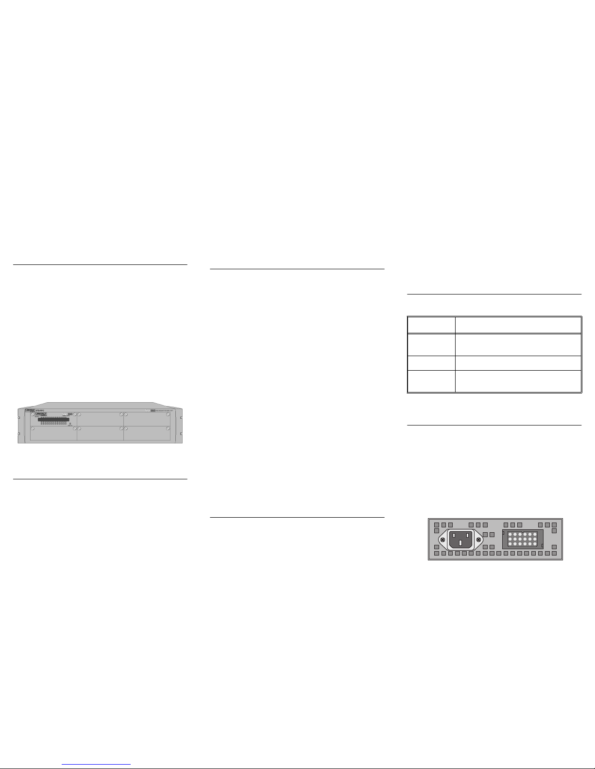
The SmartStack STS-RPC Redundant Power Center is a
chassis unit designed to hold from one to six STS-PSUs. The
STS-RPC unit can be table mounted or mounted in any
standard 19" rack.
Figure 1. STS-RPC Front Panel
Package Contents
Your STS-RPC package contains the following items:
•
One STS-RPC (with five blind panels)
•
One STS-PSU (mounted in the STS-RPC chassis)
•
One DC power cable
•
One plastic bag containing rubber pads, rack mounting
nuts and an Allen key
•
One STS-RPC/STS-PSU Installation Guide (this
document)
Your STS-PSU package contains the fol lowing items:
•
One STS-PSU Redundant Power Supply Unit
•
One DC power cable
•
One STS-RPC/STS-PSU Installation Guide (this
document)
Installing the STS-RPC Unit
Use the following steps when table-mounting the STS-RPC
Redundant Power Center:
1. Mount the four self-adhesive pads in the recesses on the
bottom of the unit.
2. Place the unit on any stable, flat surface. Leave enough
room around the unit for ventilation and access to cables.
Caution:
Place no more than three units (swit ches) direc tly on
top of any other unit. Doing so may cause damage to the lo wer
unit.
Use the following steps when rack-mounting the STS-RPC
Redundant Power Center:
1. Open the cap on the front of each bracket cover. Usin g the
Allen key supplied with the unit, remove the retaining
screws, keeping them for late r use. Push the bracket co vers
towards the back of the unit and lift them off.
2. Position the STS- RP C unit in the rack. Slide the unit up
and down until the bracket holes line up with the holes in
the rack. Using the screws from the bracket covers and the
nuts supplied with the unit, attach the unit to the rack.
Close the bracket cover caps again to conceal the screws.
Note:
Mount the STS-RPC unit in the middle of a stack of
switches so that the DC cable is able to reac h all switches.
Installing the STS-PSU Power Supply Unit
The STS-PSU unit can be table mounted or mounted in the
STS-RPC chassis.
If you are table mounting the STS-PSU uni t, simply place the
unit on any flat, stabl e surface. Leave enough room arou nd the
unit for ventilation and access to cables.
If you are mounting the STS-PSU uni t in the STS-RPC
chassis, use the following procedure:
1. Select a location for the STS-PSU unit in the STS-RPC
chassis. Any vacant slot can be used.
2. Remove the blind panel by loosening the tw o
thumbscrews.
3. Slide the STS-P SU unit into the slot and se cure the unit
with the tw o th umbscrews.
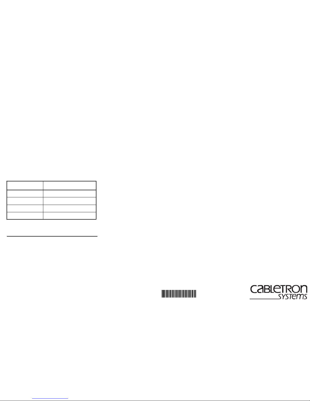
Connectors and LEDs
The STS-PSU connectors and LEDs are listed below:
Cabling and Applying P ower to the STS-PSU
Caution:
Both the SmartStack STS-PSU unit and the STS16-
20RM/STS16-20R/STS16-2 0FRM s wit ch
must be off
before
connecting or disconnecting the DC power cable.
Connect one end of the DC cable to th e DC outlet on the back
of the STS-PSU unit (either end of the cabl e can be used).
Connect the other end of the cable to the redundant power
supply connector on t he back of th e switch ( you need one STS PSU unit per switch).
Figure 2. SmartStack STS-PSU Back Panel
Name Description
DC Connector 18-pin connector for the proprietary
DC cable.
AC Connector Standard AC power rec eptacle.
Power LED The power LED is on when the
STS-PSU is receiving power.
Table 1. STS-PSU Connec tor s and LEDs
4
Using an AC power cable that meets nationa l regulations,
connect one end of the cable to the AC receptacl e on the back
of the STS-PSU unit. Connect th e other end of the cable to a
grounded power outlet or an uninterruptable power supply
(UPS). The front panel LED turns on when the unit is
receiving power.
Warning:
The STS-PSU unit does
not
have a n on/off switch.
Power is on when the unit is plugged into a power source.
Important:
The socket outlet shall be installed near the
equipment and shall be easily accessible.
To achieve redundanc y, both the switch a nd the STS- PSU unit
must be connected to a n AC outle t. Note als o that you i ncrea se
reliability by connecting the switch and the STS-PSU unit to
different power phases .
The electr i cal requiremen ts are as follows:
How the STS-PSU Works
The STS-PSU unit is connected in parallel with the internal
switch power supply via the DC cable. If the internal power
supply fails, power is provided from the STS-PSU unit, and
the switch continues to function correctly. The failure is
flagged by inte rnal logi c circui try and c an be de tected from the
management software.
❏
Trademarks
SmartStack is a trademark of Cabletron Systems, Inc. Other brand and product names are trademarks
and registered trademarks of their respective holders.
Copyrights
Cabletron reserves the right to modify th e information g iven in this publication without prior n otice. The
warranty terms and conditions applicable for your purchase of this equipment are given at the time of
purchase. Please consult them for details.
All rights reserved
. No part of this publication may be reproduced, stored in a retrieval system, or
transmitted, in any form or by any means, elec tronic, mechanica l, photocopying, re cording o r otherwise,
without the prior written permission of the publisher.
Publicat ion: OC-7061 v. 1.1, 710001741
Part Number: 9032973-01
©
April 1999 by Cabletr on Systems, Inc.
FCC Compliance
This equipment has been tested and fo und to comply with th e limits for a Class A d igital dev ice, p ursuant
to Part 15 of the FCC Rules. These limits are designed to provide reasonable protection against harmful
interference when the equipment is operated in a commercial environment. This equipment generates,
uses and can radiate radio frequency energy and, if not installed and used in accordance with the
instruction manual, may cause harmful interference to radio communications. Operation of this
equipment in a residential area is likely to cause harmful interference in which case the user will be
required to correct the interference at his own expense.
This device complies with part 15 of the FCC Rules. Operation is subject to the following two
conditions: (1) This device may not cause harmful interference, and (2) this device must accept any
interference received, including interference that may cause undesired operation.
Modifications
If the dev ice is changed or modified without the express approval of Cabletron, the user may void his or
her authority to operate the equipment.
Safety Notices
Caution:
The socket outlet shall be installed near the equipment and shall be easily accessible.
Danger:
To avoid sh ock hazard, do not connect or disconnect any cables or perfo rm installation,
maintenance, or reconfiguring of the SmartStack STS-PSU during an electrical storm.
Danger:
To avoid the possibility of electrical shock, switch powe r of f and unplug the power cord from
the outlet before detaching the power cord from the SmartStack STS-PSU.
Danger:
To avoid shock hazard the power cord must be connected to a properly wired and earthed
receptacle. Any equipment to which the SmartStack STS-PSU will be attached must also be connected
to properly wired and earthed receptacles.
Caution:
Observe the following power cable considerations before you begin installation of the SmartStack STSPSU.
1.
The socket outlet shall be installed near the equipment and shall be easily accessible.
2.
To prevent electrical shock, the power cord set used must comply with national regulations.
2a.
The female receptacle of the cord must meet CEE-22 requirements.
2b.
The cord must be UL listed, CSA labelled, and consist of three conductors with a maximum of 15
feet in length. Type SVT or SJT cord sets shall be used for units which stand on a desk or table. Type
SJT cord sets shall be used for units which stand on f loor.
2c.
The male plug for units operating at 115 VAC shall consist of a parallel blade, grounding type
attachment plug rated 15 A, 125 VAC. The male plug for units operating at 2 30 VAC shall consist of a
tandem blade, grounding type attachment plug rated 15 A, 250 VAC. The male plug for units operating
at 230 VAC (outside of the United States and Canada) shall consist of a grounding type attachment plug
rated 15 A, 250 VAC and have the appropriate safety approvals for the country in which the equipment
will be installed.
Specification Value
Voltage Range 100–240 VA C autosensing
AC Current Rating 3.2 A @ 110 V; 1.6 A @ 220 V
Thermal Dissipation 150 W
Frequency 50–60 Hz
Table 2. Electrical Requirements
* 710001741*
SmartStack STS-RPC
Redundant Power Center
SmartStack STS -PSU
Redundant Power Supply Unit
Installation Guide
 Loading...