

Page 1

STHI
INTELLIGENT
TOKEN RING STACKABLE HUB
USER’S GUIDE
CABLETRON SYSTEMS, P. O. Box 5005 Rochester, NH 03866-5005
Page 2

NOTICE
per
NOTICE
Cabletron Systems reserves the right to make changes in specifications and other
information contained in this document without prior notice. The reader should in
all cases consult Cabletron Systems to determine whether any such changes have
been made.
The hardware, firmware, or software described in this manual is subject to change
without notice.
IN NO EVENT SHALL CABLETRON SYSTEMS BE LIABLE FOR ANY
INCIDENTAL, INDIRECT, SPECIAL, OR CONSEQUENTIAL DAMAGES
WHATSOEVER (INCLUDING BUT NOT LIMITED TO LOST PROFITS)
ARISING OUT OF OR RELATED TO THIS MANUAL OR THE INFORMATION
CONTAINED IN IT, EVEN IF CABLETRON SYSTEMS HAS BEEN ADVISED OF,
KNOWN, OR SHOULD HAVE KNOWN, THE POSSIBILITY OF SUCH
DAMAGES.
© Copyright May, 1995 by:
Cabletron Systems, Inc.
P.O. Box 5005, Rochester, NH 038666-5005
All Rights Reserved
Printed in the United States of America
Order Number: 9031390 May, 1995
SPECTRUM, LANVIEW, Remote LANVIEW
trademarks of Cabletron Systems, Inc.
, and
HubSTACK
, STH, STHI, are
1
i960 is a registered trademark of Intel Corporation.
DEC and VT100
CompuServe
Windows
are trademarks of Digital Equipment Corporation.
is a registered trademark of CompuServe, Inc.
is a registered trademark of Microsoft Corporation.
Printed On
Recycled Pa
iii
Page 3

NOTICE
FCC NOTICE
This device complies with Part 15 of the FCC rules. Operation is subject to the
following two conditions: (1) this device may not cause harmful interference, and
(2) this device must accept any interference received, including interference that
may cause undesired operation.
NOTE: This equipment has been tested and found to comply with the limits for a
Class A digital device, pursuant to Part 15 of the FCC rules. These limits are
designed to provide reasonable protection against harmful interference when the
equipment is operated in a commercial environment. This equipment uses,
generates, and can radiate radio frequency energy and if not installed in
accordance with the operator’s manual, may cause harmful interference to radio
communications. Operation of this equipment in a residential area is likely to
cause interference in which case the user will be required to correct the interference
at his own expense.
WARNING: Changes or modifications made to this device which are not expressly
approved by the party responsible for compliance could void the user’s authority
to operate the equipment.
DOC NOTICE
This digital apparatus does not exceed the Class A limits for radio noise emissions
from digital apparatus set out in the Radio Interference Regulations of the
Canadian Department of Communications.
Le présent appareil numérique n’émet pas de bruits radioélectriques dépassant les
limites applicables aux appareils numériques de la class A prescrites dans le
Règlement sur le brouillage radioélectrique édicté par le ministère des
Communications du Canada.
2
3
CABLETRON SYSTEMS, INC.
PROGRAM LICENSE AGREEMENT
IMPORTANT: Before utilizing this product, carefully read this License
Agreement.
This document is an agreement between you, the end user, and Cabletron Systems,
Inc. (“Cabletron”) that sets forth your rights and obligations with respect to the
Cabletron software program (the “Program”) contained in this package. The
Program may be contained in firmware, chips or other media. BY UTILIZING THE
ENCLOSED PRODUCT, YOU ARE AGREEING TO BECOME BOUND BY THE
TERMS OF THIS AGREEMENT, WHICH INCLUDES THE LICENSE AND THE
LIMITATION OF WARRANTY AND DISCLAIMER OF LIABILITY. IF YOU DO
NOT AGREE TO THE TERMS OF THIS AGREEMENT, PROMPTLY RETURN
THE UNUSED PRODUCT TO THE PLACE OF PURCHASE FOR A FULL
REFUND.
iv
4
Page 4

NOTICE
CABLETRON SOFTWARE PROGRAM LICENSE
1. LICENSE. You have the right to use only the one (1) copy of the Program
provided in this package subject to the terms and conditions of this License
Agreement.
You may not copy, reproduce or transmit any part of the Program except as
permitted by the Copyright Act of the United States or as authorized in
writing by Cabletron.
2. OTHER RESTRICTIONS.
disassemble the Program.
3. APPLICABLE LAW. This License Agreement shall be interpreted and
governed under the laws and in the state and federal courts of New
Hampshire. You accept the personal jurisdiction and venue of the New
Hampshire courts.
You may not reverse engineer, decompile, or
EXCLUSION OF WARRANTY
AND DISCLAIMER OF LIABILITY
1. EXCLUSION OF WARRANTY.
Cabletron in writing, Cabletron makes no warranty, expressed or implied,
concerning the Program (including Its documentation and media).
CABLETRON DISCLAIMS ALL WARRANTIES, OTHER THAN THOSE
SUPPLIED TO YOU BY CABLETRON IN WRITING, EITHER EXPRESS OR
IMPLIED, INCLUDING BUT NOT LIMITED TO IMPLIED WARRANTIES
OF MERCHANTABLITY AND FITNESS FOR A PARTICULAR PURPOSE,
WITH RESPECT TO THE PROGRAM, THE ACCOMPANYING WRITTEN
MATERIALS, AND ANY ACCOMPANYING HARDWARE.
2. NO LIABILITY FOR CONSEQUENTIAL DAMAGES
SHALL CABLETRON OR ITS SUPPLIERS BE LIABLE FOR ANY DAMAGES
WHATSOEVER (INCLUDING, WITHOUT LIMITATION, DAMAGES FOR
LOSS OF BUSINESS, PROFITS, BUSINESS INTERRUPTION, LOSS OF
BUSINESS INFORMATION, SPECIAL, INCIDENTAL, CONSEQUENTIAL,
OR RELIANCE DAMAGES, OR OTHER LOSS) ARISING OUT OF THE USE
OR INABILITY TO USE THIS CABLETRON PRODUCT, EVEN IF
CABLETRON HAS BEEN ADVISED OF THE POSSIBILITY OF SUCH
DAMAGES. BECAUSE SOME STATES DO NOT ALLOW THE EXCLUSION
OR LIMITATION OF LIABILITY FOR CONSEQUENTIAL OR INCIDENTAL
DAMAGES, OR ON THE DURATION OR LIMITATION OF IMPLIED
WARRANTEES IN SOME INSTANCES THE ABOVE LIMITATIONS AND
EXCLUSIONS MAY NOT APPLY TO YOU.
Except as may be specifically provided by
. IN NO EVENT
5
6
v
Page 5

NOTICE
UNITED STATES GOVERNMENT
RESTRICTED RIGHTS
The enclosed product (a) was developed solely at private expense; (b) contains
“restricted computer software” submitted with restricted rights in accordance
with Section 52227-19 (a) through (d) of the Commercial Computer Software Restricted Rights Clause and its successors, and (c) in all respects is proprietary
data belonging to Cabletron and/or its suppliers.
For Department of Defense units, the product is licensed with “Restricted Rights”
as defined in the DoD Supplement to the Federal Acquisition Regulations, Section
52.227-7013 (c) (1) (ii) and its successors, and use, duplication, disclosure by the
Government is subject to restrictions as set forth in subparagraph (c) (1) (ii) of the
Rights in Technical Data and Computer Software clause at 252.227-7013. Cabletron
Systems, Inc., 35 Industrial Way. Rochester, New Hampshire 03866
7
vi
Page 6

CONTENTS
CHAPTER 1 Introduction
1.1 Contents of This Manual. . . . . . . . . . . . . . . . . . . . . . . . . . . 1-1
1.2 STHI Overview. . . . . . . . . . . . . . . . . . . . . . . . . . . . . . . . . .1-1
1.2.1 LANVIEW LEDs . . . . . . . . . . . . . . . . . . . . . . . . . .1-2
1.2.2 TCU Ports . . . . . . . . . . . . . . . . . . . . . . . . . . . . . . . .1-3
1.2.3 RI & RO Ports. . . . . . . . . . . . . . . . . . . . . . . . . . . . . 1-4
1.2.4 Hub-By-Hub Bypass Control . . . . . . . . . . . . . . . . . 1-5
1.2.5 Automatic Beacon Recovery Process. . . . . . . . . . .1-5
1.2.6 Support for Passive MAU Workgroups . . . . . . . . .1-5
1.2.7 Flash Downloads. . . . . . . . . . . . . . . . . . . . . . . . . . . 1-6
1.2.8 IP Address Discovery . . . . . . . . . . . . . . . . . . . . . . . 1-6
1.2.9 Local Management . . . . . . . . . . . . . . . . . . . . . . . . .1-8
1.2.10 Remote Network Management Capabilities. . . . . .1-8
1.3 Related Manuals . . . . . . . . . . . . . . . . . . . . . . . . . . . . . . . . .1-8
1.4 Getting Help . . . . . . . . . . . . . . . . . . . . . . . . . . . . . . . . . . . .1-8
CHAPTER 2 Requirements & Specifications
2.1 General Networking Considerations. . . . . . . . . . . . . . . . . .2-1
2.2 Operating Specifications. . . . . . . . . . . . . . . . . . . . . . . . . . .2-3
2.2.1 Hubstack Interconnect Cables. . . . . . . . . . . . . . . . .2-3
2.2.2 TCU and COM Ports . . . . . . . . . . . . . . . . . . . . . . . 2-3
2.2.3 Supported MIB Groups. . . . . . . . . . . . . . . . . . . . . .2-5
2.2.4 Ring Speed . . . . . . . . . . . . . . . . . . . . . . . . . . . . . . . 2-5
2.2.5 Ring Sequence . . . . . . . . . . . . . . . . . . . . . . . . . . . . 2-6
2.2.6 Safety . . . . . . . . . . . . . . . . . . . . . . . . . . . . . . . . . . .2-6
2.2.7 Computing Hardware . . . . . . . . . . . . . . . . . . . . . . .2-7
2.2.8 Environmental Requirements . . . . . . . . . . . . . . . . .2-7
2.2.9 Physical Specifications . . . . . . . . . . . . . . . . . . . . . .2-7
CHAPTER 3 Installation
3.1 Installing the STHI . . . . . . . . . . . . . . . . . . . . . . . . . . . . . . . 3-1
3.1.1 Unpacking the STHI. . . . . . . . . . . . . . . . . . . . . . . .3-1
3.1.2 Stacking the STHI. . . . . . . . . . . . . . . . . . . . . . . . . .3-2
3.1.3 Attaching the Strain Relief Bracket . . . . . . . . . . . .3-2
vii
Page 7

CONTENTS
3.1.4 Rack-Mounting the STHI . . . . . . . . . . . . . . . . . . . . 3-2
3.1.5 Wall-Mounting the STHI . . . . . . . . . . . . . . . . . . . .3-3
3.1.6 Free-Standing Installations . . . . . . . . . . . . . . . . . . .3-5
3.1.7 Connecting the STHI to the Power Source. . . . . . . 3-6
3.2 TPIM Installation . . . . . . . . . . . . . . . . . . . . . . . . . . . . . . . . 3-6
3.3 Finishing the Installation. . . . . . . . . . . . . . . . . . . . . . . . . . .3-6
CHAPTER 4 Troubleshooting
4.1 LANVIEW LED Signals . . . . . . . . . . . . . . . . . . . . . . . . . .4-1
4.2 Trouble Resolution . . . . . . . . . . . . . . . . . . . . . . . . . . . . . . .4-2
4.3 The Reset Button. . . . . . . . . . . . . . . . . . . . . . . . . . . . . . . . .4-3
4.4 NVRAM Reset Switch . . . . . . . . . . . . . . . . . . . . . . . . . . . . 4-4
CHAPTER 5 Local Management
5.1 Accessing LM. . . . . . . . . . . . . . . . . . . . . . . . . . . . . . . . . . . 5-1
5.1.1 Dumb Terminal Configuration . . . . . . . . . . . . . . . . 5-2
5.1.2 Console Cable Configuration . . . . . . . . . . . . . . . . . 5-3
5.1.3 Entering LM . . . . . . . . . . . . . . . . . . . . . . . . . . . . . .5-3
5.2 Using LM Screens. . . . . . . . . . . . . . . . . . . . . . . . . . . . . . . .5-4
5.2.1 Working with LM Screens . . . . . . . . . . . . . . . . . . .5-4
5.2.2 Screen Hierarchy. . . . . . . . . . . . . . . . . . . . . . . . . . . 5-6
5.2.3 Screen Introductions . . . . . . . . . . . . . . . . . . . . . . . .5-6
5.3 The System Level Screen . . . . . . . . . . . . . . . . . . . . . . . . . .5-8
5.3.1 System Date and System Time. . . . . . . . . . . . . . . .5-8
5.3.2 IP Address. . . . . . . . . . . . . . . . . . . . . . . . . . . . . . . .5-8
5.3.3 Subnet Mask . . . . . . . . . . . . . . . . . . . . . . . . . . . . . .5-9
5.3.4 Enable IP Address Discovery . . . . . . . . . . . . . . . . .5-9
5.3.5 Enable Beacon Recovery . . . . . . . . . . . . . . . . . . .5-10
5.3.6 MAC Address . . . . . . . . . . . . . . . . . . . . . . . . . . . .5-11
5.3.7 Locally Administered Address . . . . . . . . . . . . . . . 5-11
5.4 The SNMP Community Names Screen . . . . . . . . . . . . . .5-11
5.4.1 Community Name. . . . . . . . . . . . . . . . . . . . . . . . .5-12
5.4.2 Access Policy . . . . . . . . . . . . . . . . . . . . . . . . . . . . 5-12
5.5 The SNMP Traps Screen . . . . . . . . . . . . . . . . . . . . . . . . . 5-13
viii
Page 8

CONTENTS
5.5.1 Trap Destination . . . . . . . . . . . . . . . . . . . . . . . . . .5-13
5.5.2 Trap Community Name . . . . . . . . . . . . . . . . . . . .5-13
5.5.3 Enable Traps . . . . . . . . . . . . . . . . . . . . . . . . . . . . .5-13
5.6 The Chassis Status View Screen. . . . . . . . . . . . . . . . . . . .5-14
5.6.1 The Screen Mode Screen Command. . . . . . . . . . .5-14
5.6.2 Multiplexer Configuration Fields . . . . . . . . . . . . . 5-15
5.6.3 Port Configuration Fields . . . . . . . . . . . . . . . . . . . 5-16
5.6.4 NEXT and PREVIOUS. . . . . . . . . . . . . . . . . . . . .5-20
5.6.5 ENABLE ALL PORTS. . . . . . . . . . . . . . . . . . . . .5-20
5.6.6 REFRESH. . . . . . . . . . . . . . . . . . . . . . . . . . . . . . . 5-20
5.7 The Component Status Screen . . . . . . . . . . . . . . . . . . . . . 5-20
5.8 The Device Statistics Screen. . . . . . . . . . . . . . . . . . . . . . . 5-21
5.8.1 Screen Mode . . . . . . . . . . . . . . . . . . . . . . . . . . . . .5-22
5.8.2 REFRESH 3SEC. . . . . . . . . . . . . . . . . . . . . . . . . . 5-22
5.8.3 General Counter Fields (Group 1) . . . . . . . . . . . .5-23
5.8.4 Ring Information Fields (Group 2). . . . . . . . . . . . 5-23
5.8.5 Isolating Errors Fields (Group 3) . . . . . . . . . . . . .5-25
5.8.6 Non-Isolating Errors (Group 4) . . . . . . . . . . . . . . 5-26
5.9 The SNMP Tool Screen . . . . . . . . . . . . . . . . . . . . . . . . . . 5-27
5.9.1 Community Name. . . . . . . . . . . . . . . . . . . . . . . . .5-28
5.9.2 OID Prepend . . . . . . . . . . . . . . . . . . . . . . . . . . . . .5-28
5.9.3 GET. . . . . . . . . . . . . . . . . . . . . . . . . . . . . . . . . . . .5-28
5.9.4 GETNEXT . . . . . . . . . . . . . . . . . . . . . . . . . . . . . . 5-29
5.9.5 STEP. . . . . . . . . . . . . . . . . . . . . . . . . . . . . . . . . . .5-29
5.9.6 WALK. . . . . . . . . . . . . . . . . . . . . . . . . . . . . . . . . .5-30
5.9.7 CYCLES. . . . . . . . . . . . . . . . . . . . . . . . . . . . . . . .5-30
5.9.8 RECALL-OID. . . . . . . . . . . . . . . . . . . . . . . . . . . .5-30
5.9.9 SET . . . . . . . . . . . . . . . . . . . . . . . . . . . . . . . . . . . . 5-30
5.9.10 REPEAT . . . . . . . . . . . . . . . . . . . . . . . . . . . . . . . . 5-31
5.9.11 Firmware Image Downloads. . . . . . . . . . . . . . . . .5-31
Appendix A TPIM Specifications
A.1 Overview. . . . . . . . . . . . . . . . . . . . . . . . . . . . . . . . . . . . . . A-1
A.2 Twisted Pair TPIM Pinouts. . . . . . . . . . . . . . . . . . . . . . . . A-1
A.3 Fiber Optic TPIM Specifications . . . . . . . . . . . . . . . . . . . A-2
ix
Page 9

CONTENTS
A.3.1 TPIM-F2 for Multimode Fiber . . . . . . . . . . . . . . . A-3
A.3.2 TPIM-F3 for Single Mode Fiber. . . . . . . . . . . . . . A-4
Appendix B Media Specifications
B.1 Unshielded Twisted Pair (UTP) . . . . . . . . . . . . . . . . . . . . .B-1
B.1.1 UTP Cable Categories. . . . . . . . . . . . . . . . . . . . . . .B-1
B.1.2 UTP Lobe Lengths . . . . . . . . . . . . . . . . . . . . . . . . .B-2
B.2 Shielded Twisted Pair (STP). . . . . . . . . . . . . . . . . . . . . . . .B-3
B.2.1 STP Cable Categories. . . . . . . . . . . . . . . . . . . . . . .B-3
B.2.2 STP Lobe Lengths. . . . . . . . . . . . . . . . . . . . . . . . . .B-4
B.2.3 Mixed STP Cable Types. . . . . . . . . . . . . . . . . . . . .B-4
B.3 Single Mode and Multimode Fiber Optic Cabling . . . . . . .B-5
x
Page 10

CHAPTER 1
Introduction
Welcome to the Cabletron Systems
Ring Hub User’s Guide
understanding of the features and capabilities of the STHI. A general
knowledge of IEEE 802.5 Token Ring communications networks and their
physical layer components will be helpful.
. Please read through this manual to gain an
STHI Intelligent Stackable Token
1.1 Contents of This Manual
Chapter 1,
STHI features, and offers leads to further information.
Chapter 2,
requirements, network guidelines, and STHI operating specifications.
Chapter 3,
making network connections.
Chapter 4,
system to troubleshoot network problems.
Chapter 5,
Management application.
Introduction
Requirements & Specifications
Installation
Troubleshooting
Local Management
, outlines the contents of this manual, describes
, contains instructions for installing the STHI and
, describes how to use the LANVIEW LED
, describes how to use the Local
, describes installation
1.2 STHI Overview
The STHI is an SNMP compliant intelligent hub that provides basic
management functionality including port and station control, statistical
error and trap tracking, and enhanced beacon recovery for a Token Ring
LAN. Its front panel TCU (Trunk Connector Unit) ports allow for network
connections to either active stations or passive Multi-Station Access Units
(MAUs) while its TPIM (Token Ring Port Interface Module) ports allow
for ring expansions across a variety of media. Its rear panel HubSTACK
ports provide for ring expansion through connections to multiple STH
non-intelligent hubs. See Figure 1-1.
Page 1-1
Page 11

STHI Overview
WITH
WITH
LANVIEW®
LANVIEW
CPU
16 Mb/s
®
24X 23X 22X 21X 20X 19X
ACT
MGMT
RO
12X 11X 10X 9X 8X 7X
18X 17X 16X 15X 14X 13X
6X 5X 4X 3X 2X 1X
STACK 3STACK 2 STACK 5STACK 4
RI
HubSTACK
STHI-24
16M4M
SPEED
STHI-24
TOKEN RING HUB
SUPPORTING 100 OHM UTP CABLE
RESET
COM
TOKEN RING HUB
Figure 1-1. Front and Back Views of the STHI-24
The STHI may be installed as a fully managed stand-alone device, or it
may be stacked with up to four STH hubs, each of which adds 12 or 24
TCU ports to the LAN, bringing the total count to a maximum of 120
managed TCU ports in the stack. The STHI serves as the logical “top” of
the stack and provides full frame and error statistics for the managed ring.
The STHI fully conforms to IEEE 802.5 Token Ring specifications for
connectivity to Token Ring equipment and offers the following Token
Ring enhancement features:
• Local Management, a user interface for management control;
• Cabletron Systems’ Automatic Beacon Recovery Process (ABRP);
• Multiple Ring Out connectivity for Passive MAU workgroups;
• automatic speed fault protection;
• active filtering,
equalizing, and amplify
ing circuitry;
• and LANVIEW LEDs for “at-a-glance” diagnostic monitoring.
1.2.1 LANVIEW LEDs
Cabletron Systems’ LANVIEW status monitoring and diagnostics system
is an array of LEDs which helps users to diagnose power failures,
beaconing conditions, cable faults, and connection problems. Refer to
Section 4.1,
Page 1-2
LANVIEW LED Signals
, for more detail.
Page 12

STHI Overview
1.2.2 TCU Ports
The four STHI models are functionally identical with the exception of the
number and type of network ports they offer:
Table 1-1. TCUs and Media Types per Model
STHI-22 12 unshielded RJ45 ports
STHI-24 24 unshielded RJ45 ports
STHI-42 12 shielded RJ45 ports
STHI-44 24 shielded RJ45 ports
Each STHI is equipped with TCU ports fitted with female RJ45 modular
connector jacks to support the attachment of either STP (shielded twisted
pair) or UTP (unshielded twisted pair) cabling with RJ45 connector plugs.
Models that support STP cabling use RJ45 connectors that provide a
grounded connection for the cabling shield. See Section 2.2.2,
COM Ports
, for pinouts.
TCU and
Lobe Port and Multiple Ring Out Port Configurations
Each TCU port on the STHI is internally defaulted to operate as a lobe
interface to support the insertion of a Token Ring station into a ring.
However, each TCU port may also be reconfigured via the Local
Management (LM) application (see Section 5.6.3,
Fields
) to function as a Ring Out port which will support connections to
Port Configuration
non-intelligent, passive MAU (Multi-Station Access Unit) workgroups.
Refer also to Section 1.2.6,
Support for Passive MAU Workgroups
.
Ring Speed Fault Protection
STHI hubs also provide Ring Speed Fault Protection on each TCU port to
protect against beaconing conditions caused by stations inserting at the
wrong ring speed. If a ring speed mismatch is detected, the STHI blocks
the port to keep the misconfigured station isolated from the ring and
provides a simple visible LED signal (blinking red at the port’s LED) to
indicate that Ring Speed Fault Protection is blocking the port. The port
remains blocked until the ring speed mismatch condition is removed or
resolved.
Page 1-3
1
2
Page 13

STHI Overview
Active Circuitry
On each TCU port, STHI hubs provide active circuitry which filters,
equalizes, and amplifies all received signals before transmitting them to
the next point on the ring. The result is enhanced signal integrity and
extended maximum station lobe cable distances.
Daughter Board Upgrade Kit
The following daughter board upgrade kits may be used to expand STHI
hubs from 12 to 24 TCU ports:
• TR-UTP-UGKT for STHI-22.
• TR-STP-UGKT for STHI-42.
1.2.3 RI & RO Ports
The STHI incorporates a pair of RI/RO port sockets for Token Ring Port
Interface Modules (TPIMs). This Ring In / Ring Out port pair allows for
the expansion of the main ring to other hubs. Refer to Section 5.6.3,
Configuration Fields
, Subsection
RING OUT ENABLE Mode
Port
, for the
procedure to enable RI/RO ports.
Essentially, TPIMs are media adapters which enable their host modules to
expand their network connections to other media types. The TPIM models
listed in Table 1-2 are produced by Cabletron Systems and may be
installed in the RI/RO port sockets on the STHI. Refer to Section 3.1,
Installing the STHI
, for installation instructions.
3
4
Table 1-2. TPIMs, Supported Media, and Connectors
TPIM Media Type Connector
TPIM-T1 Shielded Twisted Pair DB9
TPIM-T2 Unshielded Twisted Pair RJ45
TPIM-T4 Shielded Twisted Pair RJ45
TPIM-F2 Multimode Fiber ST
TPIM-F3 Single Mode Fiber ST
Page 1-4
Page 14

STHI Overview
1.2.4 Hub-By-Hub Bypass Control
Unless otherwise configured by a user, all hubs in an STH/STHI stack are
interconnected to form a continuous Token Ring. Through Local
Management, however, each hub may be individually bypassed from the
continuous ring to form its own isolated ring which does not exchange
data with the other hubs.
If an STH is bypassed from the main ring, the STH module will not receive
data-dependent services such as statistical tracking and beacon recovery,
but other physical control functions such as port configuration remain
unaffected. If the STHI is bypassed, only its TCUs are actually bypassed
from the stack’s common ring: TPIM Ring ports and management systems
maintain their connection to the stack’s common ring.
Refer to Section 5.6.2,
Multiplexer Configuration Fields
, for instructions
regarding bypass control.
1.2.5 Automatic Beacon Recovery Process
To guard the network against operational interruptions due to beaconing
conditions, the STHI protects itself and its attached STH hubs with
Cabletron Systems’ advanced Automatic Beacon Recovery Process. ABRP
engages more quickly and is able to treat conditions beyond the scope of
the IEEE standard beacon recovery process. The STHI automatically
partitions problematic lobes from the ring, allowing the rest of the ring to
continue operating. The hub checks partitioned Ring In/Out ports
periodically and re-enables them automatically if they have recovered;
partitioned TCU ports remain disabled until re-enabled by a user.
1.2.6 Support for Passive MAU Workgroups
By default, each TCU port is configured to its STN (station) setting to
support lobe connections to stations. Whereas a station signals a TCU to
open its interface by providing phantom current down its lobe cable, a
passive Multi-Station Access Unit cannot provide phantom current. To
allow for MAU connections, the user may reconfigure TCU ports via Local
Management to function in Ring Out mode. A TCU port in Ring Out mode
looks for the presence of data bits, rather than phantom current, to
determine link status. Refer to Section 5.6.3,
Subsection
RING OUT ENABLE Mode
Port Configuration Fields
, for configuration instructions.
,
Page 1-5
Page 15

STHI Overview
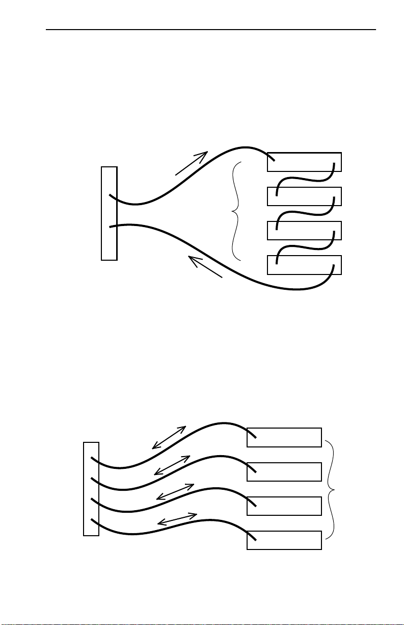
Improved Protection from Beaconing
By utilizing multiple Ring Out TCU ports, users can provide enhanced
reliability for existing networks which use passive MAUs because Ring
Out TCU ports allow for the separate attachment of each MAU. Rather
than daisy-chaining MAUs together as a single entity and risking their
collective isolation in case of beaconing, the user can now attach each
MAU individually, reducing the number of MAU ports that are at risk;
ABRP is able to bypass individual Ring Out-to-MAU connections on an
individual basis, leaving other workgroups unaffected. See Figure 1-2.
NOTE
The Ring Out TCU configuration does not provide for the
MAU’s redundant connection to the ring. To achieve dual
attachment to a MAU, use the Ring In and Ring Out TPIM
ports.
1.2.7 Flash Downloads
New and updated firmware may be downloaded into the STHI hub’s
Flash EPROMs. This process may be executed by Cabletron’s Remote
LANVIEW/Windows, version 3.0 or later, or by any device using BOOTP
or TFTP protocols. Refer to Section 5.9.11,
Firmware Image Downloads
for download instructions.
1.2.8 IP Address Discovery
1
,
The STHI supports IP Address Discovery. Through a BootP server (a
network device that holds a user-defined list of MAC addresses and
corresponding IP addresses), network managers may attribute an IP
address to any known MAC address. When the STHI is powered up
without an IP address and IP Address Discovery is enabled, it issues
BootP requests at user-set intervals, essentially asking “does anybody
know my name?” If the BootP server recognizes the MAC address, it tells
the STHI what IP address has been attributed to it. If no BootP sever
responds after 500 request cycles, the STHI automatically boots from its
own FLASH memory and remains without an IP address until a user
provides one through the Local Management interface.
Each STHI has on its backplate a sticker which indicates its MAC address.
Page 1-6
Page 16
STHI Overview
g
t
g
t
g
t
g
t
DAISY-CHAIN MAU CONFIGURATION
When MAUs are daisy-chained,
they are connected as single collective entity.
The entire chain must be bypassed
to isolate the hub from a single beaconing station.
All stations lose connection if beaconing occurs on any station.
Ring
Out
Ring
In
Hub with
Ring
Ring
Ring
Access Units
Multi-Station
Ring
In
In
In
In
(8 Stations)
(8 Stations)
(8 Stations)
(8 Stations)
Ring In / Ring Out
RING OUT TCU MAU CONFIGURATION
When each MAU is individually connected to the STHi hub,
only one MAU must be bypassed
to isolate the hub from a beaconing MAU station.
The stations on that MAU still go down,
but the remaining MAUs and their stations stay operational.
Ring
Out
Ring
Out
Ring
Out
Ring
Out
STHi TCUs
Ring
Ring
Ring
Ring
In
In
In
In
(8 Stations)
(8 Stations)
(8 Stations)
(8 Stations)
Rin
Ou
Rin
Ou
Rin
Ou
Rin
Ou
Access Units
Multi-Station
Figure 1-2. Improved Beacon Recovery Resolution for MAUs
Page 1-7
Page 17

Related Manuals
1.2.9 Local Management
The STHI hub’s Local Management application displays packet and error
statistics for the entire stack, for each individual device, or for individual
ports, and enables the user to provide management support for the STHI
and all its attached segments.
Users with actual or emulated VT100 dumb terminals may access Local
Management out-of-band via the RJ45 COM port. Refer to Section 5.1 for
connection instructions.
1.2.10 Remote Network Management Capabilities
The STHI may be managed remotely by a variety of SNMP network
management systems including the following from Cabletron Systems:
• Cabletron Systems SPECTRUM
• Cabletron Systems Remote LANVIEW/Windows
• Cabletron Systems Remote LANVIEW for SunNet Manager
1.3 Related Manuals
Use the Cabletron Systems
STH-22/24 /42/44 User’s Guide
to supplement
the procedures and other technical data provided in this manual. The
procedures contained therein are referenced where appropriate, but are
not repeated in this manual.
1.4 Getting Help
To present any questions, comments, or suggestions concerning this
manual or any Cabletron Systems Product, please contact Cabletron
Systems Technical Support:
By phone (603) 332-9400
Monday-Friday; 8am - 8pm EST
By CompuServe
By Internet mail support@ctron.com
Page 1-8
GO CTRON from any ! prompt
By Fax: (603) 337-3075
By BBS: (603) 337-3750
Page 18

By FTP ctron.com (134.141.197.25)
Login:
Password:
anonymous
your email address
By United States Cabletron Systems, Inc.
Postal Service P.O. Box 5005
Rochester, NH 03866-5005
Getting Help
Page 1-9
Page 19

CHAPTER 2
Requirements & Specifications
This chapter describes network guidelines, power requirements, and
operating specifications for the STHI. Before performing the installation,
read this chapter and confirm that the network meets the requirements
and conditions specified herein. Failure to follow these guidelines may
result in poor network performance.
Refer to Appendix A,
Refer to Appendix B,
TPIM Specifications
Media Specifications
, for TPIM specifications.
, for cable specifications.
2.1 General Networking Considerations
Take care in planning and preparing the cabling and connections for the
network. The susceptibility of the LAN’s cables to crosstalk and noise
determines the network’s error rate, and thus, the efficiency of data
propagation on the network. The quality of the connections, the length of
cables and other conditions of the installation are critical factors in
determining the quality of the network.
All devices connected to the STHI must meet IEEE 802.5 Token Ring
specifications.
Maximum Number of Stations on a Ring
The maximum stack composed of four 24-port STH hubs and one 24-port
STHI offers a total of 120 TCU ports, but the number of ports available on
the LAN may be increased by the use of passive Multi-Station Access
Units (see to Section 1.2.6,
TPIM Ring In / Ring Out connections to other devices (see Section 1.2.3,
RI & RO Ports).
Support for Passive MAU Workgroups) and
1
While there is no recommended limit to the number of TCU ports to be
made available in a stack, the recommended maximum number of stations
to be inserted simultaneously into a single ring is 255 when using STP lobe
cabling and 150 when using UTP cabling anywhere on the ring. If the ring
has been extended through RI/RO connections, consider the number of
ports on ring extensions as well as those in the stack itself.
Page 2-1
Page 20

General Networking Considerations
Crosstalk 2
Crosstalk is interference caused by signal coupling between different cable
pairs contained within a multi-pair cable bundle. Multi-pair cables should
not be used for UTP lobe cabling. Avoid mixing Token Ring signals with
other applications (voice, etc.) within the same cable.
Noise 3
Noise can be caused by either crosstalk or externally induced impulses.
Outside systems (motors, switching equipment, fluorescent lighting, high
amperage equipment) may produce electrical interference causing noise.
The number and quality of cable connections also contribute considerably
to noise levels. To reduce noise induced errors, it may be necessary to
re-route cabling away from potential noise sources, or to ensure that the
electrical wiring in the area is properly wired and grounded, or to replace
connectors along affected segments.
Temperature
Signal attenuation varies significantly with temperature when
PVC-insulated cable is used. In areas where temperatures exceed 40˚C, it
is strongly recommended that plenum-rated cables be used instead to
ensure that signal attenuation remains within specifications.
Installation Recommendations 5
In addition to complying with the cable specifications presented in
Appendix A, TPIM Specifications, the cabling installation should comply
with the following recommendations to obtain optimum performance
from the network:
• UTP cabling should be free of splices, stubs, or bridged taps.
• Metal troughs, ducts, etc. carrying Token Ring signals should be
properly grounded.
• Cables should be routed away from sources of electrical noise, such as
power lines, fluorescent lights, electric motors, radio interference, and
heavy machinery.
• Token Ring signals should not be routed through UTP cables that exit
a building or which are adjacent to cables either exiting a building or
exposed to lightning strikes and power surges.
4
Page 2-2
Page 21
Operating Specifications
• UTP cables that contain Token Ring signals should not be
simultaneously used for applications which may impress high
voltages (greater than 5 volts) with sharp rise or fall times, since the
noise coupling from such signals could directly cause errors on the
Token Ring network.
• Where practical, dedicated cable should be used for Token Ring
signals.
• Work area wall plates and outlets used for the Token Ring network
should be clearly labeled as Token Ring network lobe connections.
2.2 Operating Specifications
Cabletron Systems reserves the right to change these specifications
without notice.
2.2.1 Hubstack Interconnect Cables
Cabletron’s HubSTACK Interconnect cables (Part Number 9380141) must
be used when interconnecting STH devices with the STHI.
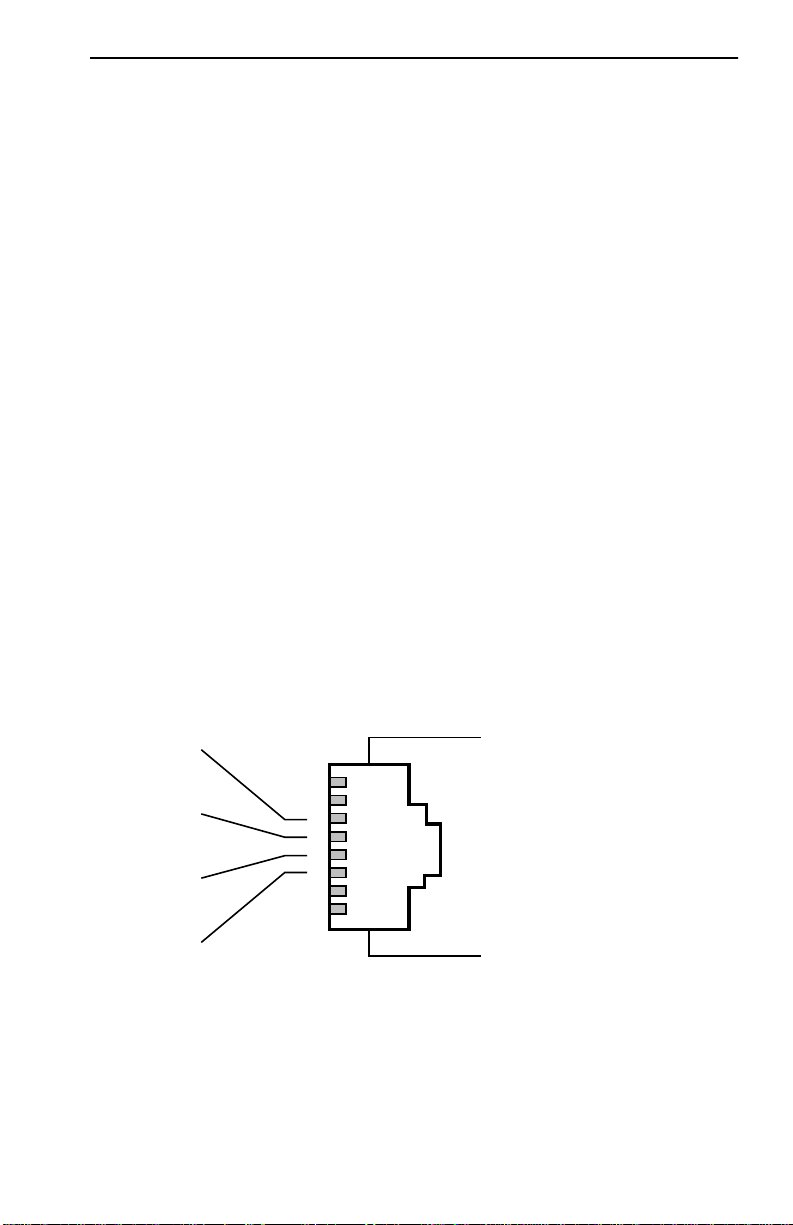
2.2.2 TCU and COM Ports
The STHI hub’s network ports are female RJ45 connectors. The pinouts
shown in Figure 2-1 are common to all STHI and STH TCU ports.
Cable Shield*
TX+
8
RX-
RX+
7
6
5
4
3
2
1
MALE
RJ45
*Cable Shield
not used
with UTP cabling
TX-
Cable Shield*
Figure 2-1. TCU pinouts
On STHI models -42/-44, each RJ45 connector is encased in a metallic
shield which provides a means of connection for the STP cable shield.
Page 2-3
Page 22
Operating Specifications
dy
Shield continuity is maintained by contacts within the female RJ45 that
contact the metallic casing of the male RJ45 on the STP lobe cable.
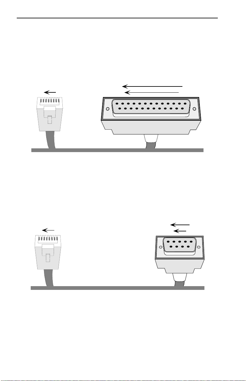
The COM port is a female RJ45 connector supporting EIA RS232C
connections via cables with pinout configurations as specified in Figure
2-2 or Figure 2-3.
RJ45 Plug
18
Female 25 Pin D-Shell
113
25 14
Transmit......Pin 1 .......to ......Pin 3 ......Receive
Receive......Pin 4....... to......Pin 2...... Transmit
Signal Ground......Pin 5....... to......Pin 7...... Signal Ground
Data Carrier Detect......Pin 2....... to......Pin 20......Data Terminal Rea
Data Terminal Ready......Pin 6....... to......Pin 5...... Clear to Send
Figure 2-2. RJ45 to DB25 Connector Pinout
RJ45 Plug
18
Female DB-9
15
96
Transmit..... Pin 1 .......to ......Pin 2 ........Receive
Receive..... Pin 4....... to......Pin 3........ Transmit
Signal Ground..... Pin 5....... to......Pin 5........ Signal Ground
Request to Send..... Pin 7....... to......Pin 7........Ready to Send
Clear to Send..... Pin 8....... to......Pin 8........Clear to Send
Figure 2-3. RJ45 to DB9 Connector Pinout
Page 2-4
Page 23

Operating Specifications
2.2.3 Supported MIB Groups
The STHI provides access to the following Management Information Base
groups and their respective functionality:
Standard MIBs 1
• MIB-2 (RFC 1231)
Cabletron Enterprise MIBs 2
• Download
• MIB-II Extensions
• Token Ring FNB (Flexible Network Bus)
• DOT 5 Physical & Logical
• Token Ring Station Assignment
• Device
• PIC MIB (Product Information Chip MIB)
• Chassis MIB
2.2.4 Ring Speed
The operating ring speed for the STHI may be set via the Ring Speed
Switch on the front face of the STHI or by MIB commands via the SNMP
Tool screen in Local Management.
The STHI hub’s Ring Speed switch setting is read only at power-up. In
order to change the ring speed via the Ring Speed switch, the user must
first change the switch setting and then reset the STHI (see Section 4.3, The
Reset Button).
MIB commands override the Ring Speed switch setting. Once the switch
setting has been overridden, the MIB command ring speed setting will
remain in effect at all subsequent power-ups as long as the switch setting
is not changed. MIB commands are accessible through the MIB Navigator
screen on the intelligent hub’s Local Management application and
through other SNMP network management software packages including
Cabletron Systems’ Remote LANVIEW
®
/Windows.
The user may cancel the MIB override and regain switch control over the
STHI hub’s ring speed by changing the current switch position and
resetting the STH by the reset button.
Page 2-5
Page 24

Operating Specifications
NOTE
When cancelling a MIB override, the user may have to reset
twice (as described in the steps below) to actually change
the STHI hub’s ring speed by the switch.
To return to switch control from a MIB-overridden Ring Speed setting:
1. Regain switch control. Regardless of the actual desired ring speed,
the user must toggle the switch out of its current position and then
reset the STHI to put a switch-position change into effect, cancelling
the MIB override.
2. Select the desired ring speed. If the Ring Speed switch setting is not
yet the desired setting (it may now be the same as the setting dictated
by the MIB command), the user must again change the switch setting
and reset the STH to complete the change from the MIB-commanded
speed setting to the desired switch-set speed setting,
2.2.5 Ring Sequence
The ring sequence for the stations on the ring (the order in which stations
are logically arranged on the ring) is determined by the physical location
of each TCU connection, progressing in ascending stack number and port
number order. The sequence is changed each time a station is inserted or
de-inserted from a ring.
To determine the ring sequence, consider only those ports inserted into the
ring. Beginning at the STHI hub’s lowest numbered inserted port, list in
ascending numerical order the number of each inserted port. If STH hubs
have been stacked to the STHI, then continue by listing those inserted in
the STH hub numbered lowest in the stack. Repeatedly move to each next
STH and list the inserted ports in numerical order until all ports inserted
into the ring have been listed. The order is continuous, wrapping directly
from the stack’s last inserted port to the first—from the bottom of the list,
right back to the top.
Hubs that are bypassed from the stack’s common ring must
TIP
not be counted in the common ring sequence; they comprise
their own separate rings with separate ring sequences.
2.2.6 Safety
This equipment is designed in accordance with UL478, UL910, NEC
725-2(b), CSA, IEC, TUV, VDE Class A, and meets FCC Part 15, Class A
limits.
Page 2-6
Page 25

Operating Specifications
2.2.7 Computing Hardware
Operating System Memory: 2.0 MB
Internal Processor: Intel i960 operating at 16 MHz
Non-Volatile RAM: 128 KB with battery back-up
EPROM: 128 KB
FLASH MEMORY: 1 MB
2.2.8 Environmental Requirements
Operating Temperature: +5° to +50° C
fluctuation ≤ 10° per hour
Non-operating Temperature: -30° to +90° C
Operating Humidity: 5 to 95% (non-condensing)
2.2.9 Physical Specifications
Dimensions: 2.8 H x 17.0 W x 8.0 D inches
(7.2 x 43.6 x 20.5 cm)
Predicted MTBF: STHI-22/42: 523,989 hours
(mean time between failure) STHI-24/44: 505,811 hours
Page 2-7
Page 26

CHAPTER 3
Installation
This chapter outlines the procedure for installing the STHI. Confirm that
the network meets the guidelines and requirements outlined in Chapter 2,
Requirements & Specifications, before installing the STHI.
3.1 Installing the STHI
The STHI may be installed as a stand-alone hub or as part of a stack.
Provided with the STHI is an accessory kit that includes rack-mount
brackets for installations into 19 inch racks, wall-mount brackets and
mounting screws for installations on walls, and a strain relief bracket to
direct the stresses inflicted by cables hanging from the TCU ports.
All installations must meet the following requirements:
• A single phase 120Vac, 15A, grounded power receptacle must be
located within 7 feet of the STHI.
• Shelving units must be able to support 30 pounds of static weight for
each device in the stack. This accounts for both hub and cable weight.
• The ambient temperature must be maintained between -30° and 90°C
at all times and between 5° and 50°C during operation.
3.1.1 Unpacking the STHI
Unpack the STHI as follows:
1. Carefully remove the STHI from the shipping box, preserving the
packaging materials for future transport.
2. Visually inspect the STHI. If there are any signs of damage, contact
Cabletron Systems Technical Support immediately.
3. Read any Release Notes or Addendums included in the shipping box.
The package includes a 3-1/2” floppy disk containing a
TIP
backup copy of the STHI’s Flash Firmware Image File
which may be downloaded to the STHI if the original image
becomes corrupted.
Page 3-1
Page 27

Installing the STHI
3.1.2 Stacking the STHI
The rear panel of the STHI has four STACK ports exclusively reserved for
connections to STH modules. Refer to the STH manual for stacking
instructions.
3.1.3 Attaching the Strain Relief Bracket
To reduce lateral stresses imposed on TCU ports and cable plugs by the
weight of cables hanging from the TCU ports of a horizontally mounted
STHI, the strain relief bracket ensures that cable forces pull nearly straight
out from the port, rather than prying sharply downward.
Attach the strain relief bracket to the front of the STHI as follows:
1. Locate the strain relief bracket and four 8-32 x 3/8” screws.
Use of longer screws may cause damage to the unit or
WARNING
electrical shock to the user.
2. Carefully turn the STHI upside down.
3. Attach the strain relief bracket to the bottom of the STHI as shown in
Figure 3-1.
RI
6X 5X 4X 3X 2X 1X
18X 17X 16X 15X 14X 13X
12X 11X 10X 9X 8X 7X
RO
24X 23X 22X 21X 20X 19X
COM
SPEED
RESET
16 Mb/s
MGMT
ACT
CPU
LANVIEW
®
16M4M
STHI-24
SUPPORTING 100 OHM UTP CABLE
TOKEN RING HUB
HubSTACK
WITH
Figure 3-1. Attaching the Strain Relief Bracket
3.1.4 Rack-Mounting the STHI
Perform these steps to install the STHI in a 19-inch rack:
1. Remove the four cover screws (two from each side) located near the
front-most edges of each side of the STHI.
2. Using the four screws removed in step 1, attach the rack-mounting
brackets to each side of the STHI as shown in Figure 3-2.
Page 3-2
Page 28

Installing the STHI
Rack Mounting Brackets (2)
®
TOKEN RING HUB
LANVIEW
HubSTACK
STHI-24
WITH
SUPPORTING 100 OHM UTP CABLE
18X 17X 16X 15X 14X 13X
6X 5X 4X 3X 2X 1X
RI
RO
24X 23X 22X 21X 20X 19X
12X 11X 10X 9X 8X 7X
CPU
16M4M
RESET
SPEED
ACT
MGMT
16 Mb/s
COM
Screws (4)
Figure 3-2. Installing the Rack-Mount Brackets
3. With the mounting brackets installed, position the STHI between the
vertical frame members of the 19-inch rack and fasten it securely with
the mounting screws as shown in Figure 3-3.
19-Inch Rack
®
TOKEN RING HUB
LANVIEW
HubSTACK
STHI-24
WITH
SUPPORTING 100 OHM UTP CABLE
18X 17X 16X 15X 14X 13X
6X 5X 4X 3X 2X 1X
RI
RO
24X 23X 22X 21X 20X 19X
12X 11X 10X 9X 8X 7X
CPU
16M4M
RESET
SPEED
ACT
MGMT
16 Mb/s
COM
Screws (4)
Figure 3-3. Installing the STHI in a Rack
3.1.5 Wall-Mounting the STHI
When an STHI is installed on a wall, it must face downward so that all
attached cables will hang straight out from the TCUs, rather than prying
at angles to the ports.
1. Use the provided 3/8” screws to attach the wall-mounting brackets to
the bottom of the STHI as shown in Figure 3-4. There are two brackets,
one for each side.
Page 3-3
Page 29

Installing the STHI
Figure 3-4. Installing the Wall-Mounting Brackets
2. Select a wall location for the STHI within 7 feet of a power outlet.
Potential SHOCK HAZARD: Select a wall location where
WARNING
pilot holes for screws will not intersect with electrical wiring
in the wall.
3. Get a pencil and refer to Figure 3-5. With the wall-mounting brackets
attached to the STHI, position the STHI against the wall where it will
be permanently mounted, with the network ports facing down, and
mark the screw holes’ positions on the wall.
4. Set the STHI aside and carefully drill four 1/4” pilot holes for the
screw anchors, one at each mark made in step 3.
5. Install the screw anchors. If installing on a hollow wall, use the
provided Molly bolt anchors (pictured in collapsed form as “Hollow
Wall Anchor” in Figure 3-5): insert the anchor into the hole, tighten the
screw to collapse the anchor’s bracing arms, and remove the screw. If
installing on a solid wall, a different type of anchor will be required.
6. Position the STHI on the wall, aligning the screw holes over the
anchors, and fasten the STHI to the anchors with the four anchor
screws. Tighten the screws.
Page 3-4
Page 30

Installing the STHI
Solid Wall Anchor
Wall-Mounting Bracket
attached to STHi
Mounting Screws
Pre-Drilled Holes
with Anchors
Hollow Wall Anchor
Figure 3-5. Wall-mounting the STHI
3.1.6 Free-Standing Installations
For a free-standing shelf of table-top installation, install the STHI on an
unrestricted free surface area 21 inches wide, 18 inched deep, and 6 inches
high, within 7 feet of its power source, as shown in Figure 3-6.
6 IN.
18 IN.
HubSTACK
STHI-24
®
TOKEN RING HUB
LANVIEW
WITH
SUPPORTING 100 OHM UTP CABLE
CPU
ACT
16M4M
MGMT
16 Mb/s
RESET
SPEED
COM
21 IN.
18X 17X 16X 15X 14X 13X
24X 23X 22X 21X 20X 19X
RO
12X 11X 10X 9X 8X 7X
6X 5X 4X 3X 2X 1X
RI
7 FT.
Figure 3-6. Shelf or Table-top Installation
Page 3-5
Page 31

TPIM Installation
3.1.7 Connecting the STHI to the Power Source
Plug one end of the power cord into the back panel of the STHI and
connect the other end into a grounded wall outlet. Verify that the PWR
LED is on, indicating that the STHI is receiving power.
3.2 TPIM Installation
TPIM use is an option, not a requirement, for STHI operation.
Electrostatic Discharge (ESD) can damage the TPIM.
!
CAUTION
Install a TPIM as follows:
1. Remove the TPIM port coverplate from the STHI hub’s faceplate.
2. Carefully insert the TPIM into the TPIM port with its edges in the
guide tracks. The TPIM seats firmly, snug against the face of the STHI
when the connector pins on the back of the TPIM are fully inserted
into their pin slots.
Observe all precautions to prevent electrostatic discharges
when handling the TPIM. Avoid touching the components
or surface of the board. Hold only the edges of the board or
the metal front panel.
3. Finger-tighten the mounting screw (upper right-hand corner of the
TPIM faceplate) to secure the TPIM in place.
3.3 Finishing the Installation
Before placing the network into service, test the installation thoroughly,
making sure that all stations can receive data and that the STHI and all
connected stations are indicating normal operation. Confirm that the
networking software is configured properly to match the installed
network. If problems emerge, proceed to Chapter 4, Troubleshooting.
Page 3-6
Page 32

CHAPTER 4
Troubleshooting
This chapter contains instructions for using LANVIEW LEDs to
troubleshoot physical layer network problems.
4.1 LANVIEW LED Signals
The STHI incorporates the Cabletron Systems LANVIEW Status
Monitoring and Diagnostics System. These LEDs can help in the diagnosis
of physical layer problems such as power failures or cable faults. Table 4-1
lists the LANVIEW LEDs and defines their messages:
Table 4-1. LANVIEW LED Signals
LED Color Condition
CPU blinking
Green
Red malfunction
ACT Green
flash
Red
flash
16 Mb Yellow Ring Speed set to 16 Mbps.
off Ring Speed set to 4 Mbps.
MGMT Green management operational
Red management failure
normal operations
normal frame received
Beacon Recovery running
Page 4-1
Page 33

Trouble Resolution
Table 4-1. LANVIEW LED Signals (Continued)
LED Color Condition
Ports off Port enabled but not linked.
Green Port enabled and linked.
Red Port disabled (or set to Ring Out) and not linked.
blinking
Ring Speed Fault -OR- Port linked but disabled.
Red
4.2 Trouble Resolution
If this section does not guide the user to a solution, please contact
Cabletron Systems Technical Support (see Section 1.4, Getting Help.)
Loss Of Power 1
If the STHI is having power problems, check the power delivery system
(power cable, power outlet, circuit breaker, fuse).
Failure to Link on Enabled Port
Check that the Token Ring devices at either end of the cable are
powered-up.
Verify that the network cable’s connectors have the proper pinouts. Refer
to Section 2.2.2, TCU and COM Ports.
Check the cable for continuity. A variety of tools are available for this test,
depending on the media being used.
Check that the cables meet specifications for dB loss as described in
Appendix A, TPIM Specifications.
2
Ring Speed Fault 3
The network device being linked at this port is operating at a ring speed
different from the STHI hub’s currently set ring speed. Set the two devices
to the same speed.
Page 4-2
Page 34

The Reset Button
Management Failure 4
If the MGMT LED is red, try resetting the STHI. If this does not resolve the
problem, contact Cabletron Systems Tech Support. Meanwhile, the STHI
will continue to operate, but will not provide Beacon Recovery or
statistical monitoring.
4.3 The Reset Button
The STHI incorporates a recessed Reset button (see Figure 4-1). Pressing
this button causes the STHI to clear all counters, run all startup
diagnostics, and reload the flash resident firmware into the CPU local
memory. It does NOT initialize Non-Volatile Random Access Memory
(NVRAM), the battery-backed random access memory where the STHI
stores network management parameters. (See also Section 4.4, NVRAM
Reset Switch.)
HubSTACK
STHI-24
16M4M
SPEED
Reset Button
NOTE
RESET
Management services will be suspended during the reset
process.
TOKEN RING HUB
SUPPORTING 100 OHM UTP CABLE
WITH
LANVIEW
CPU
16 Mb/s
COM
Figure 4-1. Reset Button
®
ACT
MGMT
RO
Page 4-3
Page 35

NVRAM Reset Switch
4.4 NVRAM Reset Switch
The STHI incorporates a recessed NVRAM Reset switch (see Figure 4-2)
which initializes NVRAM, the nonvolatile random access memory. To use
it, toggle the switch and then reset the STHI. This clears all user
configurations and settings and returns the STHI to its factory defaults.
HubSTACK
TOKEN RING HUB
STHI-24
SUPPORTING 100 OHM UTP CABLE
WITH
LANVIEW
®
16M4M
SPEED
RESET
CPU
COM
ACT
16 Mb/s
MGMT
RO
24X 23X 22X 21X 20X 19X
12X 11X 10X 9X 8X 7X
18X 17X 16X 15X 14X 13X
6X 5X 4X 3X 2X 1X
Figure 4-2. NVRAM Switch
RI
NVRAM
RESET SWITCH
IN HERE
Page 4-4
Page 36

CHAPTER 5
Local Management
This chapter explains how to set up a console to access the STHI’s Local
Management interface (LM) and explains how to use LM screens and
commands.
NOTE
LM enables the user to perform the following actions on the STHI and all
of its attached segments:
• assign an IP address and subnet mask to the STHI;
• select a default gateway for the transmission of SNMP traps;
• configure, enable, and disable ports throughout the stack;
• control access to the STHI through community names;
• designate which Network Management Stations (NMS) are to receive
trap messages from the device;
• access and manipulate the Management Information Base (MIB);
• and view statistics regarding errors, beacons, and traffic for the entire
stack, individual module, or individual port.
Users wishing to skip instructions for connecting a
management terminal to the STHI may proceed directly to
Section 5.2 for instructions regarding the use of LM.
5.1 Accessing LM
To access LM, the user needs the following equipment:
• an actual or emulated Digital Equipment Corporation VT series
terminal.
• a console cable to attach the management terminal to the STHI. Refer
to Section 2.2.2, TCU and COM Ports for pinout information.
NOTE
The STHI is shipped with a UTP console cable with RJ45
connectors on each end and adapters for DB9 or DB25
connections. The user must provide the terminal.
Page 5-1
Page 37

Accessing LM
5.1.1 Dumb Terminal Configuration
Configure the LM console according to the parameter settings defined in
Table 5-1. On VT100/200/300 series terminals, press F3 to access the Setup
Directory. For setup parameters not listed in the following table, any
selection should be acceptable. Refer to terminal’s manual for more
instructions if necessary.
Table 5-1. Setup Requirements for LM Console
Menu Parameter Setting
Display Setup: Columns 80 Columns
Controls Interpret controls
Auto wrap No Auto wrap
Text Cursor No Cursor
General Setup: Mode VT100, 7 bit control
Cursor keys Normal cursor keys
Communications
Setup:
Transmit (all values from 2400 to
19,200 accepted)
Receive Receive = transmit
Bits, parity 8 Bits, no parity
Stop Bit 1 Stop Bit
Local Echo No Local Echo
Port Data Leads Only
Auto Answerback No Auto Answerback
Keyboard Setup: Keys Typewriter keys
Margin bell Margin bell
Warning bell Warning bell
Auto Answerback No Auto Answerback
Page 5-2
Page 38

Accessing LM
5.1.2 Console Cable Configuration
Connect the console cable to the STHI as follows:
1. Attach the male RJ45 connector to the COM port of the STHI.
2. Attach the female end to the 25-pin or 9-pin COM port on the terminal.
5.1.3 Entering LM
After configuring the LM terminal and properly attaching the cable to the
STHI, the user may access the Local Management interface.
1. Activate the console: power up the terminal, or run the emulator
program. After the STHI is fully booted, the STHI Password screen
shown in Figure 5-1 appears on the console’s monitor.
STHI LOCAL MANAGEMENT
Cabletron Systems, Incorporated
P.O. Box 5005
Rochester, NH 03866-5005
(603) 332-9400
(c) Copyright Cabletron Systems, Inc. 1995
Flash Image Version: 1.00.00
Boot EPROM Version: 01.00.00
Board Revision: 112
Enter User Password:
Figure 5-1. Password Screen
2. Enter a password. (There are two factory default passwords for
super-user access: “public” and a blank entry.) Then press the Return
key.
Passwords are user-definable and may be accorded varying degrees
of access to the functions of LM. Refer to Section 5.4, The SNMP
Community Names Screen, for details.
If the password entry is invalid, the entry is cleared and the cursor returns
to the beginning of the password entry field. If the password is valid, the
associated access level in effect for the session is reported briefly on the
Page 5-3
Page 39

Using LM Screens
e
ds
e
bottom line of the screen, then the Main Menu screen shown in Figure 5-2
appears.
STHI LOCAL MANAGEMENT Flash Image Version: 1.00.00
Screen Title Line
MAIN MENU
DEVICE SETUP
DEVICE STATUS
DEVICE STATISTICS
SNMP TOOL
EXIT LM
Screen Commands Line
Event Message Lin
Menu Items or Fiel
Field Sensitive Help Lin
Figure 5-2. Main Menu with Screen Anatomy Labels
NOTE
As a precaution against unauthorized access, if LM detects
no keyboard activity for 15 minutes, it closes the current
session and returns to the Password screen.
5.2 Using LM Screens
5.2.1 Working with LM Screens
This section describes how to work with all LM screens. Refer to Figure 5-2
for screen anatomy.
Invoking Menu Options or Screen Commands 1
1. Use the Tab key or arrow keys to highlight the item.
2. Press the Return key.
Invoking a menu option opens the named screen.
Invoking a screen command executes the named action. The RETURN
screen command returns the user from the current screen to its parent
screen. The SAVE or EXECUTE screen commands record all entries set on
the screen and put them into effect.
Page 5-4
Page 40

Using LM Screens
Setting or Modifying Fields 2
The Field Sensitive Help Line offers help while certain fields are selected.
The Event Message Line reports the status of certain field-related actions
(e.g.: “Saved OK” or “Bad Value”).
1. Use the Tab key or arrow keys to highlight fields.
2. Set the new value:
With toggle fields (those that appear in square brackets), use the
Return key to scroll through to the desired option.
There are two edit methods available in each editable field. All
editable fields offer the same first method: replace the entire current
string simply by typing into the field. As for the second method, some
fields offer “return to default,” others offer “overstrike.” If a field has
a default value, the default may be restored simply by selecting the
field and pressing Return. If the field has no default, pressing Return
activates the overstrike mode whereby the user may use the arrow
keys to move through the current string and replace individually
selected characters by typing new ones in their place. Press Return
again to exit overstrike mode.
3. Invoke the SAVE command at the bottom of the screen to store all
settings currently shown on the screen, or skip this step to throw away
all recent screen edits since last save when exiting the screen.
If a user with an ineligible access level attempts to edit a restricted-access
field, a message of refusal appears on the Event Message line. Refer to
Section 5.4.2, Access Policy for details.
Exiting the Local Management Interface Session
1. Return to the Main Menu by invoking RETURN on each screen.
2. Invoke the Main Menu’s EXIT LM command to close the session and
return to the Password Screen. (Enter a password to regain entry.)
The user may leave the connection active, or simply disconnect the
terminal or stop the emulator program.
Page 5-5
3
Page 41

Using LM Screens
5.2.2 Screen Hierarchy
Figure 5-3 illustrates the organization of the entire LM screen system.
Password Screen
Main Menu
Device
Setup
System Level
SNMP Community Names
SNMP T r aps
Device
Status
Chassis Status
Component Status
SNMP T ool
Device Statistics
Figure 5-3. LM Screen Hierarchy
The Main Menu screen offers access to the Device Setup screen, the Device
Status screen, the Device Statistics screen, and the SNMP Tool screen.
5.2.3 Screen Introductions
System Level
The System Level screen (Section 5.3) is used to provide the STHI with
basic configuration settings including IP address, Locally Administered
physical address, subnet mask, Beacon Recovery options, and Runtime IP
Address Discovery.
1
SNMP Community Names 2
The SNMP Community Names screen (Section 5.4) is used to specify
SNMP community names and their respective levels of access to LM
(read-only, read-write, super-user).
Page 5-6
Page 42

Using LM Screens
SNMP Traps 3
The SNMP Traps screen (Section 5.5) is used to designate which Network
Management Workstations will receive SNMP traps from the STHI, and to
provide those stations with community names for access to various MIBs.
Chassis Status View 4
The Chassis Status View screen (Section 5.6) is used to monitor and
configure the modules in the stack, to set operational configurations for
TCU ports and RI/RO ports, and to execute port/module bypassing.
Component Status 5
The Component Status screen (Section 5.7) is used to view the operational
status of various functional entities within the STHI.
Device Statistics
The Device Statistics screen (Section 5.8) is used to view network
performance statistics and network configuration information.
SNMP Tool 7
The SNMP Tool screen (Section 5.9) is used to view and manipulate MIB
objects.
6
Page 5-7
Page 43

The System Level Screen
5.3 The System Level Screen
Access the System Level screen (Figure 5-4) from the Device Setup menu.
STHI LOCAL MANAGEMENT Flash Image Version: 1.00.00
SYSTEM LEVEL
System Date: 06/15/10 System Time: 13:08:00
IP Address Subnet Mask
SNMP Agent 134.141.143.141 255.255.0.0
Enable IP Address Discovery: [YES] State: [SEEKING ]
Retry Interval (0001-9999 Mins): 0015
Enable Beacon Recovery: [YES]
Number of Retries (000-100, 999=infinite): 004
Retry Interval (000-999 Secs): 021
FNB MAC Address - Physical: 00-00-B8-00-00-00
FNB MAC Address - Locally Administered: 00-00-B8-E8-A5-B1
SAVE RETURN
Figure 5-4. System Level Screen
5.3.1 System Date and System Time
Use these fields to set the correct date and time.
Type the date into the field in a MM/DD/YY format for the date, and
HH:MM:SS for the time. If the format entered is invalid, the message
“Invalid Date” or “Invalid Time” appears and the edit is rejected.
5.3.2 IP Address
Use this field to set the host Internet Protocol (IP) address for the STHI.
If the IP Address is changed, the STHI will execute a soft-reset after SAVE
is invoked to re-initialize all affected parameters.
Only a user with Super-User access can change the device’s
TIP
IP address. See Section 5.4 for information about
Super-User access.
Page 5-8
Page 44

The System Level Screen
5.3.3 Subnet Mask
The Subnet Mask determines how the STHI directs SNMP Trap messages
(discussed in Section 5.5). The mask defines the portion of the trap
destination’s IP address to be compared to the IP address of the STHI. If
the designated address portions match, the destination station is
determined to exist on the same subnet as the STHI; Network
Management Stations (NMS) within the STHI hub’s own subnet are
addressed directly. Traps destined for stations on other subnets are sent
through a router.
• Set a new value for the Subnet Mask when workstations designated to
receive traps reside on a different subnet. In most cases, 255.255.0.0
(the 8-bit subnet mask) is the appropriate mask.
• Use the Subnet Mask setting of 0.0.0.0 when all workstations
designated to receive trap messages exist within the same subnet as
the STHI.
If the Subnet Mask is changed, the STHI will execute a soft-reset after
SAVE is invoked to re-initialize all affected parameters.
5.3.4 Enable IP Address Discovery
This Yes/No toggle field is used to enable/disable IP Address Discovery.
(Refer to Section 1.2.8, IP Address Discovery.) Use the Return key to
toggle the field. When the toggle field set to YES and SAVE is invoked, the
accompanying State field indicates that the device is SEEKING an IP
Address. If it finds one, the State field indicates ACQUIRED. If it fails 500
times, it displays FAILED.
Retry Interval
The Retry Interval field determines the duration between automatic
attempts at IP Address Discovery. Each attempt takes about one
half-minute. The STHI then waits for as many minutes as specified in the
Retry Interval field before trying again. This cycle continues until the
address is acquired, the IP Address Discover feature is disabled, or the
process is attempted 500 times.
To force an immediate check, rather than waiting for the
TIP
next cycle, toggle Enable IP Address Discovery to NO
and then to YES again, and then invoke SAVE.
Page 5-9
1
Page 45

The System Level Screen
5.3.5 Enable Beacon Recovery
This field allows the user to enable or disable the STHI’s Advanced Beacon
Recovery Process (ABRP).
Beaconing is part of a standard IEEE 802.5 Token Ring process by which a
Token Ring LAN attempts to recover from cable or hardware problems by
automatically locating and bypassing the fault, thereby restoring network
communications without operator intervention. Networks that rely upon
the IEEE standard beaconing process are disabled when beaconing fails.
Cabletron’s ABRP protects against such network stoppages.
NOTE
ABRP is supported only by Cabletron products. To secure
the reliability of ABRP beaconing protection for the entire
network, use only Cabletron Systems devices.
If beacon recovery is enabled, ABRP is automatically invoked whenever
the STHI detects a beaconing condition on the ring. It is often able to
correct the problem before the standard IEEE process even begins. Once
ABRP locates the problem and corrects it, the STHI generates traps to
provide the network’s designated remote management station with the
following information regarding the incident:
• the beaconing device’s address;
• the address of the beaconing device’s Nearest Active Upstream
Neighbor (NAUN);
• the beacon type;
• the duration of the beaconing condition;
• and the port(s) and/or modules left in bypass to partition the
problematic ring segment.
Number of Retries
Use the Number of Retries field to determine how many times the STHI
will attempt to re-enable an RI or RO port which has been disabled by
ABRP. If the beaconing condition still exists when the port is checked, the
port is not allowed to re-enable.
1
The field accepts values from 000 to 100, and also accepts 999 to indicate
infinite retries. The default number of retries is 4.
Page 5-10
Page 46

The SNMP Community Names Screen
Retry Interval 2
The Retry Interval field determines the duration between automatic retries
of RI/RO ports disabled by ABRP. Intervals are selectable to a resolution
of 7 seconds between ring port retry attempts. The default setting is 21.
5.3.6 MAC Address
This read-only field displays the Media Access Control (MAC) address
which, by universal default, identifies the hub at the network’s physical
layer.
5.3.7 Locally Administered Address
Users may assign a locally administered address which is used instead of
the MAC address to identify the FNB interface at the network’s physical
layer. If enabled, the locally administered address takes effect after the
next reset of the STHI.
5.4 The SNMP Community Names Screen
Access the SNMP Community Names screen, shown in Figure 5-5, from
the Device Setup menu.
STHI LOCAL MANAGEMENT Flash Image Version: 1.00.00
SNMP COMMUNITY NAMES
Component Name Community Name Access
STHI Chassis MGR public READ-ONLY
STHI Chassis MGR public READ-WRITE
STHI Chassis MGR public SUPER-USER
SAVE RETURN
Figure 5-5. Community Name Table Screen
Page 5-11
Page 47

The SNMP Community Names Screen
The SNMP Community Names screen enables the user to establish or
modify the community names which serve as passwords to LM and to
determine the level of security access the LM user is accorded.
5.4.1 Community Name
Use these fields to define community name strings. Each name set in these
fields will be accorded the security access level named on the same line to
the right, in the Access Policy column.
5.4.2 Access Policy
The Access Policy column indicates the access status accorded to the
corresponding community name. Three pre-configured levels of LM
access are available:
Read-only
This level of access allows a user partial access to view LM screens. The
user will not be allowed to write to any field in LM, nor will the user be
allowed to view the super-user or read-write community names.
Read-write 2
This level of access allows a user to view LM screens and to change values
set in them, including the read-only community name. The user will not
be able to write to the IP Address, the Subnet Mask, or read-write
community name fields, nor will the user will be allowed to view the
super-user name.
Super-user 3
This level of access is absolute and will grant a user full LM access
privileges to read and edit any LM parameters, including community
names.
1
Page 5-12
Page 48

The SNMP Traps Screen
5.5 The SNMP Traps Screen
Access the System Level screen (Figure 5-6) from the Device Setup menu.
STHI LOCAL MANAGEMENT Flash Image Version: 1.00.00
SNMP TRAPS
Trap Destination Trap Community Name Enable Traps
0.0.0.0 <CR> N
0.0.0.0 <CR> N
0.0.0.0 <CR> N
0.0.0.0 <CR> N
0.0.0.0 <CR> N
0.0.0.0 <CR> N
0.0.0.0 <CR> N
0.0.0.0 <CR> N
SAVE RETURN
Figure 5-6. SNMP Traps Screen
The SNMP Traps screen is used to provide the STHI with the IP addresses
of remote management stations intended to receive SNMP traps, and to
provide those stations with the community names they will need to access
the STHI with SNMP requests.
5.5.1 Trap Destination
Use these fields to set an IP Address for each workstation designated to
receive trap alarms from the STHI.
5.5.2 Trap Community Name
SNMP protocol requires that all traps issued include an SNMP community
name. This field holds the community name to be sent to the
corresponding network device. Some network management systems
make use of this community name when polling the STHI.
5.5.3 Enable Traps
Setting the value in this toggle field to YES enables the STHI to send SNMP
trap messages to the corresponding device; NO disables the same.
Page 5-13
Page 49

The Chassis Status View Screen
5.6 The Chassis Status View Screen
Access the Chassis Status View screen (Figure 5-7) from the Device Status
menu.
STHI LOCAL MANAGEMENT Flash Image Version: 1.00.00
CHASSIS STATUS VIEW ( OPERATIONAL )
5 4 3 2 1
STH24 STH24 STH24 STH24 STHI24
Multiplexer Line
|---> <---> <-B-> <---> <---|
Ring Speed Line
16Mb/s 16Mb/s 16Mb/s 16Mb/s 16Mb/s
1 BYP 1 BYP 1 BYP 1 BYP 1 INS
2 INS 2 INS 2 LNK 2 BYP 2 INS
3 ENB 3 LNK 3 ENB 3 ENB 3 INS
4 INS 4 LNK 4 INS 4 LNK 4 INS
5 LNK 5 INS 5 INS 5 LNK 5 INS
Port Fields
6 INS 6 INS 6 ENB 6 LNK 6 ENB
7 ENB 7 ENB 7 ENB 7 ENB 7 ENB
8 ENB 8 ENB 8 ENB 8 ENB 8 ENB
9 INS 9 INS 9 ENB 9 INS 9 ENB
10 INS 10 INS 10 INS 10 INS 10 BYP
11 INS 11 INS 11 INS 11 INS 11 LNK
12 ENB 12 ENB 12 ENB 12 INS 12 ENB
NEXT [ OPERATIONAL ] [ REFRESH 3sec ] RETURN
Figure 5-7. Chassis Status View Screen with Anatomy Labels
Functions of the Chassis Status View Screen
Each column in the Chassis Status View screen displays current status
information about a module in the stack. Use the Chassis Status View
screen for the following functions:
• view/change the connection settings between modules throughout
the stack,
• view/change the current status of each port,
• view the ring speed setting,
• and configure each TCU port for station or Ring Out connections.
All hub devices are polled at user-defined intervals and the screen is
dynamically updated to show current settings and status readings.
5.6.1 The Screen Mode Screen Command
The Chassis Status View screen offers three different modes of operation,
each of which brings different functionality to the screen’s port and
multiplexer fields.
Page 5-14
1
Page 50

The Chassis Status View Screen
• OPERATIONAL (read-only) lists each port’s operational status.
• ADMINISTRATIVE allows the user to enable/disable ports and to
place entire hubs in bypass mode.
• RING OUT ENABLE allows the user to set TCU ports to station or Ring
Out operational configurations.
The roles of these modes are discussed further in the following sections
regarding port fields and multiplexer fields.
Use the toggling command field in the center of the screen command line
to select the screen mode.
5.6.2 Multiplexer Configuration Fields
All hubs in an STH/STHI stack are interconnected to form a single Token
Ring LAN, logically organized and represented on the LM screen
(Figure 5-7, page 5-14) as a string of left/right neighbors. The multiplexer
fields on the multiplexer line indicate the state of each hub’s connection to
the common Token Ring LAN that interconnects all hubs in the stack. In
OPERATIONAL and RING OUT ENABLE modes, the multiplexer fields are
read-only, but in ADMINISTRATIVE mode, all multiplexer fields become
toggle fields, allowing the user to manipulate the connections between
hubs in the stack.
The multiplexer field allows the user to bypass individual hubs from the
stack’s common ring. A bypassed hub operates as its own local ring,
providing interconnectability for all of its TCU ports, but not permitting
data contact with the stack’s common ring. If the STHI is bypassed, its
ring-monitoring functionality continues to serve the stack’s common ring,
rather than the STHI’s bypassed ring. Also, if the STHI is bypassed, its
TPIM ports continue to provide access to the stack’s common ring.
Multiplexer field symbols are defined below. Left/right connections are
not user-configurable through LM; they are determined by the physical
configuration of the interconnect cables between the STHI and any STH
hubs. Only the bypass setting is user-configurable. Toggle the multiplexer
field to select the bypass setting for each hub.
The following multiplexer status symbols may appear.
<–––> Attached left/right - This STH is connected to the stack’s
common ring. The ring connection is continued by neighbor
hubs in both directions.
Page 5-15
Page 51

The Chassis Status View Screen
<–B–> Attached left/right & Bypassed - This STH is bypassed from
the stack’s common ring. The ring connection is continued by
neighbor hubs in both directions.
|–––> Attached right - This STH is connected to the stack’s common
ring. The ring connection is continued by a neighbor hub to
the right.
|–B–> Attached right & Bypassed - This STH is bypassed from the
stack’s common ring. The ring connection is continued by a
neighbor hub to the right.
<–––| Attached left - The STHI is connected to the stack’s common
ring. The ring connection is continued by an STH to the left
and possibly extended through TPIM Ring In / Ring Out
ports as well.
<–B–| Attached left & Bypassed - The STHI is bypassed from the
stack’s common ring, but the common ring connection is
continued by an STH to the left and possibly extended
through TPIM Ring In / Ring Out ports as well.
|–––| Detached - The STHI is connected to the stack’s common ring.
There are no neighbor hubs, but the common ring may be
extended through TPIM Ring In / Ring Out ports.
|–B–| Detached & Bypassed - The STHI is bypassed from the stack’s
common ring. There are no neighbor hubs, but the common
ring may be extended through TPIM Ring In / Ring Out
ports.
5.6.3 Port Configuration Fields
The Chassis Status View screen lists all the ports from all the hubs in the
stack. TCU ports are shown in numbered ranges of 12 at a time, and TPIM
ports are listed last.
The function of each port field is determined by the screen mode currently
in effect.
ADMINISTRATIVE Mode
With the Chassis Status View screen in ADMINISTRATIVE mode
(Figure 5-8), all Port Status fields become toggle fields which allow the
user to change the current administrative state of each port.
Page 5-16
1
Page 52

The Chassis Status View Screen
Each port field (whether TPIM or TCU) may be set as follows:
ON The port is enabled and will allow insertion.
OFF The port is disabled.
STHI LOCAL MANAGEMENT Flash Image Version: 1.00.00
CHASSIS STATUS VIEW ( ADMINISTRATIVE )
5 4 3 2 1
STH24 STH24 STH24 STH24 STHI24
|---> <---> <-B-> <---> <---|
16Mb/s 16Mb/s 16Mb/s 16Mb/s 16Mb/s
1 [OFF] 1 [OFF] 1 [OFF] 1 [OFF] 1 [ON]
2 [ON] 2 [ON] 2 [OFF] 2 [OFF] 2 [ON]
3 [ON] 3 [OFF] 3 [ON] 3 [ON] 3 [ON]
4 [ON] 4 [OFF] 4 [ON] 4 [OFF] 4 [ON]
5 [OFF] 5 [ON] 5 [ON] 5 [OFF] 5 [ON]
6 [ON] 6 [ON] 6 [ON] 6 [OFF] 6 [ON]
7 [ON] 7 [ON] 7 [ON] 7 [ON] 7 [ON]
8 [ON] 8 [ON] 8 [ON] 8 [ON] 8 [ON]
9 [ON] 9 [ON] 9 [ON] 9 [ON] 9 [ON]
10 [ON] 10 [ON] 10 [ON] 10 [ON] 10 [OFF]
11 [ON] 11 [ON] 11 [ON] 11 [ON] 11 [OFF]
12 [ON] 12 [ON] 12 [ON] 12 [ON] 12 [ON]
NEXT [ ADMINISTRATIVE ] [ REFRESH 3sec ] RETURN
Figure 5-8. Chassis Status View Screen in ADMINISTRATIVE Mode
Page 5-17
Page 53

The Chassis Status View Screen
RING OUT ENABLE Mode 2
With the Chassis Status View screen in RING OUT ENABLE mode
(Figure 5-9), all Port Status fields become toggle fields which allow the
user to set the current configuration of each TCU port to either station or
Ring Out.
STHI LOCAL MANAGEMENT Flash Image Version: 1.00.00
CHASSIS STATUS VIEW ( RING OUT ENABLE )
5 4 3 2 1
STH24 STH24 STH24 STH24 STHI24
|---> <---> <-B-> <---> <---|
16Mb/s 16Mb/s 16Mb/s 16Mb/s 16Mb/s
1 [STN] 1 [RO] 1 [RO] 1 [STN] 1 [RO]
2 [RO] 2 [STN] 2 [STN] 2 [STN] 2 [STN]
3 [STN] 3 [STN] 3 [STN] 3 [STN] 3 [STN]
4 [STN] 4 [STN] 4 [STN] 4 [STN] 4 [STN]
5 [STN] 5 [STN] 5 [STN] 5 [STN] 5 [STN]
6 [RO] 6 [RO] 6 [STN] 6 [STN] 6 [STN]
7 [STN] 7 [STN] 7 [STN] 7 [STN] 7 [STN]
8 [STN] 8 [STN] 8 [STN] 8 [STN] 8 [STN]
9 [RO] 9 [RO] 9 [STN] 9 [STN] 9 [STN]
10 [RO] 10 [RO] 10 [STN] 10 [STN] 10 [STN]
11 [RO] 11 [RO] 11 [STN] 11 [STN] 11 [STN]
12 [STN] 12 [STN] 12 [STN] 12 [STN] 12 [STN]
NEXT [ RING OUT ENABLE ] [ REFRESH 3sec ] RETURN
Figure 5-9. Chassis Status View Screen in RING OUT ENABLE Mode
Each TCU port may be toggled to:
STN The port is configured to support connections by network
devices which are capable of generating phantom current.
RO The port is configured to support connections by passive
network devices (e.g. Multi-station Access Units) which are
not capable of generating phantom current.
Page 5-18
Page 54

The Chassis Status View Screen
OPERATIONAL Mode 3
In OPERATIONAL mode (Figure 5-7), the Chassis Status View screen is
read-only, displaying the operational status of all ports throughout the
stack. The possible states for Ring ports differ from those for STN TCUs.
STHI LOCAL MANAGEMENT Flash Image Version: 1.00.00
CHASSIS STATUS VIEW ( OPERATIONAL )
5 4 3 2 1
STH24 STH24 STH24 STH24 STHI24
|---> <---> <-B-> <---> <---|
16Mb/s 16Mb/s 16Mb/s 16Mb/s 16Mb/s
1 BYP 1 BYP 1 BYP 1 BYP 1 INS
2 INS 2 INS 2 LNK 2 BYP 2 INS
3 ENB 3 LNK 3 ENB 3 ENB 3 INS
4 INS 4 LNK 4 INS 4 LNK 4 INS
5 LNK 5 INS 5 INS 5 LNK 5 INS
6 INS 6 INS 6 ENB 6 LNK 6 ENB
7 ENB 7 ENB 7 ENB 7 ENB 7 ENB
8 ENB 8 ENB 8 ENB 8 ENB 8 ENB
9 INS 9 INS 9 ENB 9 INS 9 ENB
10 INS 10 INS 10 INS 10 INS 10 BYP
11 INS 11 INS 11 INS 11 INS 11 LNK
12 ENB 12 ENB 12 ENB 12 INS 12 ENB
NEXT [ OPERATIONAL ] [ REFRESH 3sec ] RETURN
Figure 5-10. Chassis Status View Screen in OPERATIONAL Mode
Each Ring port (TPIM port or Ring Out TCU) may be listed as:
ACT The enabled ring port has opened its connection, having
detected data on the line. The attached device is inserted into
a ring.
WRP The port is in the wrap state. Either the port is disabled, or is
not detecting data and is remaining closed.
Each station TCU port may be listed as:
INS The port is enabled and the attached device is applying
phantom current. The device is inserted into the ring.
ENB The port is enabled but no phantom current is present.
BYP The port is disabled (see ADMINISTRATIVE mode) and no
phantom current is present.
LNK An attached device is applying phantom current, but the port
is disabled, preventing insertion of the attached device into
the ring.
Page 5-19
Page 55

The Component Status Screen
5.6.4 NEXT and PREVIOUS
The Chassis Status View screen lists ports in ranges of 12 at a time. Use the
NEXT and PREVIOUS screen commands to view ports from the next or
previous range.
5.6.5 ENABLE ALL PORTS
Invoke this screen command to enable all ports in the stack. It is available
only in ADMINISTRATIVE mode.
5.6.6 REFRESH
The user may toggle this screen command to select screen refresh intervals
from 3 to 10 seconds.
5.7 The Component Status Screen
Access the Component Status screen (Figure 5-11) from the Device Status
menu.
STHI LOCAL MANAGEMENT Flash Image Version: 1.00.00
COMPONENT STATUS VIEW
COMPONENT NAME
STHI Chassis MGR
STHI LIM
STHI Protocol stack
STHI SNMP agent
Network 1
REFRESH 3sec RETURN
Figure 5-11. Component Status Screen
The Component Status View screen is a read-only screen which lists the
enabled/disabled status of the STHI hub’s operating system and
associated components. (Software applications, resources, and functions
registered in the STHI are known as components.) All compatible
Page 5-20
Page 56

The Device Statistics Screen
components, whether optionally available or included with the STHI, are
listed on the Component Status View screen. Components not yet
installed in the STHI are listed as disabled.
The Component Status View screen may list the following entities:
• Chassis Mgr - the entity that controls the interconnections between
the hubs in the stack managed by the STHI.
• Local Mgmt - the Local Management application.
• SNMP Agent - the entity for the SNMP management agent.
• Protocol Stack - the entity for the device driver protocol stack.
• Network - Numbered LANs (including both bypassed and common
rings) currently configured in the STHI.
The user can establish separate Community Name access for each
component and change its enabled/disabled status via the SNMP Tool
screen (Section 5.9), or through a remote management application such as
Remote LANVIEW/Windows’ MIB Tree utility.
5.8 The Device Statistics Screen
Access the Device Statistics screen (Figure 5-12) from the Main Menu.
STHI LOCAL MANAGEMENT Flash Image Version: 1.00.00
DEVICE STATISTICS (TOTAL)
INTERFACE: 1
RING INFORMATION
Frames Received: 2083 Active Monitor Addr: 00-00-B8-F0-13-40
KBytes Received: 194 Ring Status: Normal
Errors Received: 0 Ring Number: 0
Beacon States: 0 Stations on Ring: 2
Ring Purges: 0 Ports Enabled: 24
Active Monitor Changes: 0 Ring Speed (Mb/s): 16
ISOLATING ERRORS NON-ISOLATING ERRORS
Line Errors: 0 Lost Frame Errors: 0
Burst Errors: 0 Frame Copied Errors: 0
AC Errors: 0 Rcvr Congestion Errors: 0
Abort Transmit Errors: 0 Token Errors: 0
Internal Errors: 0 Frequency Errors: 0
ACCUMULATE DELTA REFRESH 3sec RETURN
Figure 5-12. Device Statistics Screen in TOTAL Mode
Page 5-21
Page 57

The Device Statistics Screen
This read only screen enables the user to monitor the performance of the
managed network. The error statistics provided here can be useful in the
diagnosis of LAN problems.
The counters are updated at each screen refresh.
5.8.1 Screen Mode
The screen operates under three different counting modes, described
below. The screen mode currently in effect is listed in parentheses on the
screen title line. The remaining two modes-in-waiting are listed on the
screen command line. To select another screen mode, invoke it from the
screen command line.
TOTAL 1
In this mode, the counters display totals since the STHI hub’s last reset.
DELTA 2
In this mode, the counters display totals since last screen refresh.
ACCUMULATE 3
In this mode, the screen provides a CLEAR screen command which clears
all counters, enabling the user to monitor network performance from a
user-determined moment. Clear Date and Clear Time fields are
provided to note the moment the counters were reset.
DEVICE STATISTICS (ACCUMULATE)
INTERFACE: 1
Clear Date: 01/01/89 Clear Time: 00:02:21
RING INFORMATION
Frames Received: 0 Active Monitor Addr: 00-00-B8-00-00-00
KBytes Received: 0 Ring Status: Normal
Figure 5-13. Device Statistics Screen in ACCUMULATE Mode
5.8.2 REFRESH 3SEC
The user may toggle this screen command to select counter update
intervals from 3 to 10 seconds.
Page 5-22
Page 58

The Device Statistics Screen
5.8.3 General Counter Fields (Group 1)
Frames Received 1
This displays the number of frames received by the STHI.
KBytes Received 2
This displays the amount of data (in kilobytes) received by the STHI.
Errors Received 3
This displays the number of Isolating and Non-Isolating Errors (described
below) detected on the ring.
Beacon States 4
This displays the number of beacon conditions detected on the ring.
Stations transmit beacons when they detect bit streaming or signal loss on
the ring.
Ring Purges
This displays the number of ring purge frames transmitted by the active
monitor.
Active Monitor Changes 6
This displays the number of times the role of active monitor has been
transferred between stations.
5.8.4 Ring Information Fields (Group 2)
Ring Information provides ring status information.
Active Monitor Addr 1
This displays the MAC address of the current active monitor. The active
monitor is the station designated (automatically by Token Ring protocol)
to initiate recovery procedures in response to various error conditions.
Page 5-23
5
Page 59

The Device Statistics Screen
Ring Status 2
This displays the status of the ring to which the STHI is currently
connected: if the STHI is bypassed, it refers only to the STHI hub’s internal
ring; otherwise, it refers to the stack’s common ring.
• Unknown — This reflects a transient state during which the
management agent is unable to determine the current ring status.
• Closed —The STHI has disconnected itself completely from other
hubs in the stack: it is not supporting the common ring and cannot
determine the ring state.
• Normal — The ring is operating trouble-free.
• Purge — The active monitor has issued a ring purge command to
clear all circulating transmissions. Communications will be restored
momentarily—when the active monitor releases a new token.
• Contention — The ring has entered into the active monitor
contention process to determine a new active monitor for the ring.
• Beaconing — The STHI has detected a beacon frame.
• Lobe Fail — A station failed the lobe self-test when attempting to
insert into the ring; soft-errors may have occurred.
Ring Number
This identifies the ring on which a bridge is available. Zero indicates that
there is no bridge on any ring in the stack.
Stations on a Ring 4
This displays the number of stations currently inserted into the ring. If the
STHI is bypassed, only the stations on the STHI’s self-supported ring are
counted.
Ports Enabled 5
This displays the number of TCU ports currently enabled.
Ring Speed 6
This displays the STHI hub’s currently set ring speed.
Page 5-24
3
Page 60

The Device Statistics Screen
5.8.5 Isolating Errors Fields (Group 3)
Frames reporting isolating errors provide information that can be used to
determine the physical domain of a fault. These errors are common soft
errors, meaning that they are to be expected and can be overcome by
normal Token Ring operations. While they will not completely halt a
network, excessive soft errors reduce a network’s efficiency.
Line Errors 1
Line Errors are corrupted frames normally caused by stations entering and
leaving the ring. Replacement frames are automatically generated.
This error can also indicate a problem with the receiver of the reporting
node, or the transmitter of its Nearest Active Upstream Neighbor
(NAUN), or the cabling and hub hardware between them.
Burst Errors
A burst error is an absence of clocking signals at a node’s receiver. This
error normally occurs when passive stations (those that do not generate
phantom current) enter or leave the ring.
This error can also indicate a problem with the receiver of the reporting
node, or the transmitter of its NAUN, or the cabling and hub hardware
between them.
AC Errors 3
These Address Recognized/Frame Copied errors may indicate that the
reporting station’s NAUN is faulty—unable to set the address recognized
indicator and/or frame copied indicator bits in the frame which it has
copied, leaving the downstream node with an incorrect NAUN address.
Abort Transmit Errors 4
This displays the number of abort delimiter frames transmitted by a
station. A frame of this type may indicate that either the reporting node
has detected an error on itself, or there is an error with its NAUN or the
cabling and wiring hubs between them.
2
Page 5-25
Page 61

The Device Statistics Screen
Internal Errors 5
Internal errors may be detected by the adapter’s hardware and/or
firmware. These errors cause the adapter to remove itself from the ring
and indicate a problem with the adapter hardware or firmware.
5.8.6 Non-Isolating Errors (Group 4)
Frames reporting non-isolating errors do not provide sufficient
information to determine the physical domain of a fault. These errors are
common soft errors, meaning that they are to be expected and can be
overcome by normal Token Ring operations. While they will not
completely halt a network, excessive non-isolating errors reduce a
network’s efficiency.
Lost Frame Errors
A Lost Frame Error may indicate that an adapter did not detect the return
of the end of a frame it transmitted; the frame was lost somewhere on the
ring. This can be caused by stations entering or leaving the ring.
Replacement frames are automatically generated.
Frame Copied Errors 2
A Frame Copied Error may indicate that a station received a frame with its
address as the destination, but the address recognized indicator bits were
not set to zero. This is primarily caused by stations having duplicate
physical addresses (at least one of which would be a Locally Administered
address). All MAC addresses are unique. Ensure that any Locally
administered addresses assigned do not duplicate another network
device’s physical address.
Rcvr Congestion Errors 3
A Rcvr Congestion Error may indicate that a station has
received/repeated a frame addressed to it, but had no buffer space
available to copy the frame. Replacement frames are automatically
generated, but an excessive amount of these errors may indicate a
hardware problem.
1
Page 5-26
Page 62

The SNMP Tool Screen
Token Errors 4
A Token Error may indicate that an active monitor either has detected a
recirculating frame or token, or has found that its Timer Valid
Transmission (TVX) time has expired before any token has been detected
circulating on the ring (i.e.: a lost frame error has occurred). The active
monitor is responsible for purging the ring and issuing new tokens in
response to these errors.
Frequency Errors 5
A Frequency Error may indicate that the frequency of the incoming signal
deviates excessively from that of the reporting station’s onboard crystal
oscillator. When frequency errors are detected, the ring enters the monitor
contention process to establish a new active monitor.
5.9 The SNMP Tool Screen
Access the SNMP Tool screen (Figure 5-14) from the Main Menu.
STHI LOCAL MANAGEMENT Flash Image Version: 1.00.00
SNMP TOOLS
COMMUNITY NAME: public
OID PREPEND: 1.3.6.1
GET SET GETNEXT WALK RECALL OID STEP CYCLES REPEAT
F6 F7 F8 F9
RETURN
F10
Figure 5-14. SNMP Tool Screen
Through the SNMP Tool screen, the user can access information stored in
the STHI hub’s Management Information Base (MIB). MIBs and their
objects are logically arranged as trees with subsequent branches and
leaves; each leaf is a MIB object. One leaf, for example, contains the hub’s
Page 5-27
Page 63

The SNMP Tool Screen
IP address; another contains the current operational status of TCU port
number 6. To access a specific bit of information, the user specifies an
object identifier (OID) which is a series of numbers separated by decimal
points that indicates the path through a MIB trunk and subsequent
branches to the specific leaf that contains the desired information,
effectively identifying the MIB object.
On the SNMP Tool screen, a row of MIB commands is presented. These
commands, which are described below, may be invoked in the same
manner as screen commands. Some of them may also be invoked through
function keys.
5.9.1 Community Name
The Community Name field lets the user input a password to access MIBs
that have been set up to refuse access to users without the proper
password.
5.9.2 OID Prepend
It is likely that many of the MIB leaves which the user will be accessing
will reside within the same family of branches in the MIB (e.g.: they all
begin with 1.3.6.1). The user may use the OID Prepend field to specify a
prefix (e.g.: 1.3.6.1) which will be applied automatically (unless otherwise
directed) to subsequent OIDs, allowing the user to leave out this OID
portion when accessing MIB leaves on a common family of branches.
5.9.3 GET
Use the GET command to view a single MIB leaf by specifying its OID. It
displays the following information for each MIB object:
• Specified OID - lists the OID for each object displayed.
• Size - lists the number of memory bytes occupied by the object.
• Type - lists the object’s variable type (e.g., int = integer).
• Data - lists the object’s current value.
1. Invoke GET on screen or press the F6 function key.
2. After “<GET> OID (=|F9)” appears, specify the desired OID by one of
the following methods:
• Enter the OID minus the OID’s prepend: if the prepend is 1.3.6.1,
and the user enters 4.1.3, OID 1.3.6.1.4.1.3 is requested.
Page 5-28
Page 64

The SNMP Tool Screen
• Enter an ‘=’ followed by the complete OID. This bypasses the OID
prepend specified above, enabling the user to digress from the
current MIB branch and access MIB leaves on other branches. If
the user enters =4.1.3, then OID 4.1.3 is requested.
• Press F9 to recall the last-specified OID, and then edit that OID as
desired.
3. Press the Return key.
If there is no instance of that OID, the message, “MIB NO INSTANCE”
will appear; otherwise, information about the corresponding MIB
leaf’s data type, length, and value appear.
5.9.4 GETNEXT
Use the GETNEXT command to view the MIB leaf numerically following a
specified OID.
1. Invoke GETNEXT by the on-screen selection method, or press the F8
key.
2. After “<GETNEXT> OID (=|F9)” appears, specify an OID by the same
methods used in the GET procedure:
• Enter an OID minus the OID’s prepend.
• Enter an ‘=’ to bypass the OID prepend, and follow with a
complete OID.
• Press F9 to recall the last-specified OID, and then edit that OID as
desired.
3. Press the Return key.
5.9.5 STEP
STEP functions like GETNEXT, scrolling through a MIB leaf by leaf, but it
does not ask the user to specify an OID. Instead, it simply recalls the
last-specified OID and gets the next one, allowing the user to display one
OID after another, simply by pressing Return to advance each step.
1. Invoke STEP by the on-screen selection method and press Return.
SNMP Tool gets the next object.
2. Repeatedly press Return to display subsequent objects. This can be
repeated until all sublayers of the MIB have been shown.
Page 5-29
Page 65

The SNMP Tool Screen
5.9.6 WALK
WALK functions like an automatically repeating STEP, rapidly scrolling
through a MIB leaf by leaf from a user-specified OID without requiring the
user to initiate each step. WALK steps continuously until either the user
stops the process or the list ends.
1. Invoke WALK by the on-screen selection method.
2. After “<INITIAL> OID (=|F9)” appears, specify an OID from which
to begin walking, and press the Return key.
The screen will begin walking through the MIB’s sublayers.
3. Press the Space Bar to stop the walk (or to resume if stopped), or wait
for “***MIB WALK COMPLETED***” to appear on the screen.
5.9.7 CYCLES
CYCLES functions like WALK except that the user specifies the number of
steps to be taken and the time to elapse between each step, allowing the
user to limit the speed and duration (content) of the display.
1. Invoke CYCLES by the on-screen selection method.
2. After “ENTER CYCLE COUNT:” appears, set the number of steps to
be taken, then press the Return key.
3. After “ENTER CYCLE DELAY (secs):” appears, set the delay (in
seconds) to occur between steps, then press the Return key.
4. After “<INITIAL> OID (=|F9)” appears, specify an OID from which
to begin walking, and press the Return key.
5.9.8 RECALL-OID
RECALL-OID is a tool of convenience used only when specifying an OID.
Rather than retyping the last-specified OID, the user presses F9 and the
OID appears. RECALL-OID may be invoked only by pressing F9.
5.9.9 SET
SET enables users with read-write and super-user access to change the
current values of modifiable MIB objects. For example, a super-user may
change the current community name protecting a certain MIB, or change
the STHI hub’s operating ring speed.
1. Invoke SET on screen, or press the F7 function key.
Page 5-30
Page 66

The SNMP Tool Screen
2. After “<SET> OID (=|F9)” appears, specify an OID by the same
methods used in the GET procedure:
3. Press the Return key.
If there is no instance of that OID, “MIB NO INSTANCE” will appear;
otherwise “DATA TYPE:” appears.
4. Designate a data type for the OID: integer, string, null, OID, IP
address, counter, gauge, timeticks, and opaque are the available
options. (Refer to the MIB for proper data type.) Press the Return key
to accept the designation.
5. After “DATA” appears, enter the MIB object’s new value and press
Return.
If accepted, “<SET> OPERATION CODE: xxxx <OK>” appears,
otherwise an error message appears.
5.9.10 REPEAT
The REPEAT command is the same as a GET command expect that it
re-executes itself continuously, scrolling updated values for the specified
OID on the screen and counting the number of times it has been shown,
until stopped by the user. In other words, by using REPEAT the user can
monitor an object’s changes over time.
5.9.11 Firmware Image Downloads
The SNMP Tool screen may be used to initiate a Flash file download. The
user will need to know the IP address of the TFTP server and the full path
name of the firmware image to be downloaded from that server.
Set the following OIDs as prescribed below in order to properly initiate
and complete the download.
• ctDLForceOnBoot - 1.3.6.1.4.1.52.4.1.5.8.1.1.0
Cabletron’s Download Force On Boot OID determines whether the
STHI will force a Flash image download at next reset or will boot from
its current Flash file. Set this integer value to 1 to force the download
(or 0 to disable).
• ctDLTFTPRequestHost - 1.3.6.1.4.1.52.4.1.5.8.1.4.0
Cabletron’s Download TFTP Request Host OID holds the IP address
of the designated TFTP server. Set it to the IP address of the TFTP
server which contains the image to be downloaded.
Page 5-31
Page 67

The SNMP Tool Screen
• ctDLCommitRAMtoFlash - 1.3.6.1.4.1.52.4.1.5.8.1.2.0
Cabletron’s Download Commit RAM to Flash OID determines
whether the downloaded image will be committed to Flash memory
after a successful download. Set this integer value to 1 to commit the
downloaded image to Flash (or 0 to disable). If not committed to Flash,
the downloaded file will be lost at power-down.
• ctDLTFTPRequest - 1.3.6.1.4.1.52.4.1.5.8.1.5.0
Cabletron’s Download TFTP Request OID holds the full pathname of
the file to be downloaded. Set it to the fully qualified path name of the
image file to be downloaded.
• ctDLInitiateColdBoot - 1.3.6.1.4.1.52.4.1.5.8.1.3.0
Cabletron’s Download Initiate Cold Boot OID is an integer value.
When set to 1, it forces the STHI to reset and reboot. This OID must be
set last, because the STHI will reset immediately after processing this
request.
Page 5-32
Page 68

APPENDIX A
TPIM Specifications
A.1 Overview
Token Ring Port Interface Modules (TPIMs) are media adapter cards
which extend network connections onto a variety of media. When
installed into Ring In and Ring Out ports, TPIMs support the expansion of
a Token Ring from the host module into other devices. Each TPIM has a
different type of cable port to support a different media connection. Table
A-1 lists each available Cabletron Systems TPIM and its respective
connector.
Table A-1. TPIMs and their Corresponding Media
TPIM Media Type Connector
TPIM-T1 Shielded Twisted P air DB9
TPIM-T2 Unshielded Twisted P air RJ45
TPIM-T4 Shielded Twisted P air RJ45
TPIM-F2 Multimode Fiber Optic ST
TPIM-F3 Single mode Fiber Optic ST
The LNK (Link) LED on the face of each TPIM indicates the following:
• Green - Inserting.
• Red (TPIM-T1/T2/T4 only) - No Link (Autowrapped)
• Off - No Link (Wrapped or Disabled)
All Cabletron TPIMs are interchangeable and hot-swappable.
A.2 Twisted Pair TPIM Pinouts
Each TPIM that supports Twisted Pair cabling has two operating modes:
Ring In / Ring Out and Station. For use with STHI, the TPIM is switched
to operate in Ring In/ Ring Out mode. The pinouts for TPIMs in station
applications are different from pinouts for Ring In / Ring Out
applications. Illustrations of the Ring In / Ring Out pinouts follow.
Page A-1
Page 69

Fiber Optic TPIM Specifications
TPIM-T1 TPIM-T2 and TPIM-T4
54321
9876
1. Receive +
2. Ground
3. +5V at 250 mA
4. Ground
5. Transmit -
6. Receive -
7. Ground
8. Ground
LNK
TPIM-T1
1 2 3 4 5 6 7 8
TPIM-T4
1. Not Used
2. Not Used
3. Transmit -
4. Receive +
5. Receive -
6. Transmit +
7. Not Used
8. Not Used
9. Transmit +
Figure A-1. TPIM-T1/T2/T4 Pinouts for Ring In.
TPIM-T1 TPIM-T2 and TPIM-T4
54321
9876
1. Transmit +
2. Ground
3. +5V at 250 mA
4. Ground
5. Receive -
6. Transmit -
7. Ground
8. Ground
LNK
TPIM-T1
1 2 3 4 5 6 7 8
TPIM-T4
1. Not Used
2. Not Used
3. Receive -
4. Transmit +
5. Transmit -
6. Receive +
7. Not Used
8. Not Used
9. Receive +
LNK
LNK
Figure A-2. TPIM-T1/T2/T4 Pinouts for Ring Out.
A.3 Fiber Optic TPIM Specifications
TPIM-F2 and TPIM-F3 support Multimode and Single Mode Fiber Optic
cabling respectively. Figure A-3 shows the face layout common to both
modules.
Page A-2
Page 70

Fiber Optic TPIM Specifications
RX
TX
LNK
TPIM-F2
Figure A-3. The TPIM-F2 Faceplate.
A.3.1 TPIM-F2 for Multimode Fiber
The TPIM-F2 connector supports Multimode Fiber Optic Cabling.
Table A-2. TPIM-F2 Specifications.
Parameter
Receive
Typical
Value
Worst Case
-30.5 dBm -28.0 dBm — —
Worst Case
Budget
Typical
Budget
Sensitivity
Peak Input
-7.6 dBm -8.2 dBm — —
Power
Transmitter Power:
50/125 µm -13.0 dBm -15.0 dBm 13.0 dB 17.5 dB
62.5/125 µm -10.0 dBm -12.0 dBm 16.0 dB 20.5 dB
100/140 µm -7.0 dBm -9.0 dBm 19.0 dB 23.5 dB
-10
Error Rate: Better than 10
The transmitter power and receive sensitivity levels given in Table A-2 are
Peak Power Levels after optical overshoot. A Peak Power Meter must be
used to correctly compare the given values to those measured on any
particular port. If Power Levels are being measured with an Average
Power Meter, then 3 dBm must be added to the measurement to correctly
compare those measured values to the values listed in Table A-2 (i.e. -30.5
dBm peak=-33.5 dBm average).
Page A-3
Page 71

Fiber Optic TPIM Specifications
C
A.3.2 TPIM-F3 for Single Mode Fiber
The TPIM-F3 connector supports Single Mode Fiber Optic cabling.
Transmitter Power decreases as temperatures rise. Use the Output Power
Coefficient (-0.15 dBm) to calculate increased or decreased power output
for the operating environment. For example, the typical power output at
25°C is -16.4 dBm. For a 4°C temperature increase, multiply the typical
coefficient (-0.15 dBm) by four and add the result to typical output power:
(4 x -0.15 dBm + -16.4 = -17.0).
Maximum Sensitivity (-36.0)
Receive
Sensitivity
Maximum
Receive
Input Power
Typical Sensitivity (-31.0)
Minimum Sensitivity (-30.0)
Minimum Receive Input (-9.72)
Typical Receive Input (-7.5)
Maximum Receive Input (-6.99)
Transmitter Power*
(At 25°C into
8.3/125µm fiber)
-40 -35 -30 -25 -20 -15 -10 -5 0
dBm
Less Power
* Transmit Power Typical Power Minimum Power Maximum Power
Coefficient
(See Note Below)-0.15dBm/ °C -0.12 dBm/ °C-0.18 dBm/ °
Maximum Transmit Power (-12.0)
Typical Transmit Power (-15.5)
Minimum Transmit Power (-21.0)
More Power
Figure A-4. Transmitter Power Levels
Table A-3. TPIM-F3 Specifications
Parameter Typical Minimum Maximum
Transmitter
1300 nm 1270 nm 1330 nm
Peak W a ve Length
Spectral Width 60 nm – 100 nm
Rise Time 3.0 nsec 2.7 nsec 5.0 nsec
Page A-4
Page 72

Fiber Optic TPIM Specifications
Table A-3. TPIM-F3 Specifications (Continued)
Parameter Typical Minimum Maximum
Fall Time 2.5 nsec 2.2 nsec 5.0 nsec
Duty Cycle 50.1% 49.6% 50.7%
Bit Error Rate: Better than 10
-10
The transmitter power levels given in Table A-3 are Peak Power Levels
after optical overshoot. A Peak Power Meter is required to correctly
compare the values given above to those measured on any particular port.
When measuring power levels with an Average Power Meter, add 3 dBm
to the average power measurement to correctly compare the average
power values measured to the values listed in Table A-3 (i.e., -33.5 dBm
average + 3 dB = -30.5 dBm peak).
Page A-5
Page 73

APPENDIX B
Media Specifications
Use of the STHI may involve a variety of cable types. The STHI hub’s
network ports support either Shielded Twisted Pair (STP) or Unshielded
Twisted Pair (UTP) cabling, depending on the STHI model, while Token
Ring Port Interface Modules (TPIMs) allow for network expansions onto
UTP, STP, Multimode Fiber Optic, and Single Mode Fiber Optic cabling.
The HubSTACK Interconnect cable (Part Number 9380141) which is
needed to interconnect an STH hub with an STHI is provided with each
STH.
Take care in planning and preparing the cabling and connections for the
network. The quality of the connections and the length of cables are critical
factors in determining the reliability of the network.
B.1 Unshielded Twisted Pair (UTP)
STHI models 22 and 24 and TPIM-T2 support D-inside wiring (DIW) voice
grade Unshielded Twisted Pair (UTP) cable as described below and in
EIA SP-1907B. All category 5, all category 4, and some (see Section 2.3.2 on
page 5) category 3 UTP cables meet Token Ring network performance
requirements.
B.1.1 UTP Cable Categories
Both UTP modules (STHI-22 / 24) support UTP cables classified as
category 3, 4, and 5.
UTP cable is categorized according to the following specifications:
Category 3 consists of (usually) four Unshielded Twisted Pairs of 24 AWG
solid wire for data or voice communication. (IBM Type 3 is coincidentally
the same as UTP Category 3.) It is typically used to wire cable runs within
the walls of buildings. In some installations, pre-existing UTP building
wiring can be used for Token Ring cabling.
At 16 Mbps ring speeds, some Category 3 cable does not meet
WARNING
the performance requirements of a Token Ring network.
This may impose lower limits on lobe cable distances and
ring node counts. See Table B-1.
Page B-1
Page 74

Unshielded Twisted Pair (UTP)
Table B-1. UTP Cable Category Specifications
UTP
Cat.
Operating
Frequency
Electrical
Impedance
Signal
Attenuation
per 100m
NEXT
loss
(@ ≥100m)
3 4 MHz ≤ 100Ω ±15% ≤ 5.6 dB ≥ 32 dB
16 MHz ≤ 100Ω ±15% ≤ 13.1 dB ≥ 23 dB*
4 4 MHz ≤ 100Ω ±15% ≤ 4.3 dB ≥ 47 dB
16 MHz ≤ 100Ω ±15% ≤ 8.9 dB ≥ 38 dB
5 4 MHz ≤ 100Ω ±15% ≤ 4.3 dB ≥ 63 dB
16 MHz ≤ 100Ω ±15% ≤ 8.2 dB ≥ 44 dB
*below Token Ring performance requirement of ≥ 30.5 dB.
Categories 4 and 5 are higher quality versions of category 3. They use the
same gauge of wire but demonstrate superior performance due to
improvements in material quality and assembly (e.g. more twists per foot).
Because Near-End Crosstalk (NEXT) contributes the
WARNING
majority of its detrimental effects near the end of a lobe
cable, the quality of jumper cables and patch cables is
critical. Seek the highest practical grade. The quality of
connectors and terminators is also critical.
DO NOT connect UTP cabling to any non-Token Ring
WARNING
network conductors (telephone, etc.) or ground. If in doubt,
test wiring before using. Telephone Battery and Ringing
voltages used in UTP telephone circuits may present a shock
hazard and may damage Token Ring equipment when
connected to Token Ring cabling.
B.1.2 UTP Lobe Lengths
The physical length of the cable connecting a station to a TCU port on the
STHI is referred to as the lobe length. The maximum lobe length
attainable under ideal conditions, is shown in Table B-2. Cable routing,
connector attenuation, noise, and crosstalk can adversely affect the
maximum lobe length.
Page B-2
Page 75

Shielded Twisted Pair (STP)
Table B-2. UTP Maximum Lobe Lengths.
@ 4 Mbps @ 16 Mbps
UTP
Category
meter
s
(feet)
meter
s
(feet)
3 200 (656) 100* (328)*
4 225 (738) 110 (360)
5 250 (820) 120 (393)
* for cable with NEXT loss ≥ 30.5 dB per 100m
Some UTP category 3 cables fail to meet the performance minimums
required to support a Token Ring network. Whereas category 3 allows for
near end crosstalk (NEXT) loss as low as 23 dB per 100 m at 16 Mbps,
Token Ring performance requirements demand a NEXT loss of at least
30.5 dB. To safeguard against worst case conditions (running at 16 Mbps
and using category 3 cable with the category’s lowest qualifying NEXT
loss—23 dB), the recommended maximum lobe length should be reduced
to keep crosstalk interference within acceptable levels.
B.2 Shielded Twisted Pair (STP)
STHI models 42 and 44 and TPIM models T1 and T4 support all STP cables
classified as IBM Types 1, 2, 6, and 9, all of which meet Token Ring
network performance requirements.
B.2.1 STP Cable Categories
The supported STP cable types meet the following specifications:
IBM Type 1 consists of two shielded twisted pairs (STP) of 22 AWG solid
wire for data. Used for the longest cable runs within the walls of buildings.
IBM Type 2 consists of six pairs of unshielded twisted pairs of 24 AWG
solid wire and a shield casing. The two pairs carried within the shield
casing are used to carry Token Ring data. The four pairs carried outside of
the shield casing are typically used for voice communication. Type 2 is
frequently used to wire cable runs within the walls of buildings.
Page B-3
Page 76

Shielded Twisted Pair (STP)
Table B-3. STP Cable Type Specifications.
IBM
Type
Operational
Frequency
Impedance
Attenuation per...
1000 m (1000 ft)
1 & 2 4 MHz ≤ 150Ω ±15% ≤ 22 dB (≤ 6.7 dB)
16 MHz ≤ 150Ω ±15% ≤ 45 dB (≤ 13.7 dB)
6 & 9 4 MHz ≤ 150Ω ±15% ≤ 33 dB (≤ 10.0 dB)
16 MHz ≤ 150Ω ±15% ≤ 66 dB (≤ 20.0 dB)
IBM Type 6 consists of two STP of 26 AWG stranded wire for data.
Because of its high attenuation, Type 6 is used only in patch panels or to
connect devices to/from wall jacks. Attenuation for Type 6 cable is 3/2 x
Type 1 cable (attenuation for 66 m of Type 6 = attenuation for 100 m of
Type 1).
IBM Type 9 is similar to Type 1, but uses 26 AWG solid wire. Like Type 6,
because of its high attenuation, Type 9 is used only in patch panels or to
connect devices to/from wall jacks. Attenuation for Type 9 cable is 3/2 x
Type 1 cable (66 m of Type 9 = 100 m of Type 1).
NOTE
IBM Types 6 & 9 are to be used only for lobe connections
from station to wall jack and patch panels.
B.2.2 STP Lobe Lengths
The maximum lobe length attainable under ideal conditions, is shown in
Table B-4. Cable routing, connector attenuation, noise and crosstalk can
adversely affect the maximum lobe length.
B.2.3 Mixed STP Cable Types
If cable types are to be mixed in the LAN, compensations must be made
for the different cable attenuations. For example, Type 6 & 9 cables can be
run for only 2/3 the distance of Type 1: 100 meters of Type 1 ≈ 66 meters
of Types 6 or 9)
Page B-4
Page 77

Single Mode and Multimode Fiber Optic Cabling
Table B-4. STP Maximum Lengths
IBM
Type
1 & 2 200 meters
6 & 9 30 meters
Max. Lobe Length Max. Drive Distance
4 Mbps 16 Mbps 4 Mbps 16 Mbps
(660 feet)
(99 feet)
100 meters
(300 feet)
30 meters
(99 feet)
770 meters
(2525 feet)
513 meters
(1683 feet)
346 meters
(1138 feet)
230 meters
(755 feet)
B.3 Single Mode and Multimode Fiber Optic Cabling
TPIM models F2 and F3 support multimode and singlemode fiber optic
cable respectively. Table B-5 below defines total signal attenuation
tolerances for fiber cabling. Both media have a typical constant attenuation
rate per km of fiber cable and each connector on the cable system
contributes significant additional attenuation. Maximum drive distances
define maximum allowable cable length.
Table B-5. Signal Tolerances for Fiber Optic Cable
Cable T ype
T otal
Allowable
Attenuation
Maximum
Drive Distance
50/125 µm 13.0 dB or less 2 km (2187.2 yards)
62.5/125 µm 16.0 dB or less
100/140 µm 19.0 dB or less
Multimode
Typical Signal Attenuation Rate: ≤ 2.5 dB/km.
8/125-12/125 µm 10.0 dB or less 10 km (10936.0 yards).
Single
NOTE
Typical Signal Attenuation Rate: ≤ 0.5 dB/km.
The attenuation values shown in Table B-5 include the
attenuation attributable to cables, connectors, patch panels,
and reflection losses due to impedance mismatches in the
segment.
Page B-5
 Loading...