

Cabletron Systems SSIM-T8-04 Installation Manual
1 2 3
SSIM-T8-04 Token Ring
SmartStack Interface Module
Introduction
The SmartStack SSIM-T8-04 provides four additional Token
Ring ports for the base SmartStack STS16-20RM or FRM
Token Ring Switch. These ports are IEEE 802.5J compliant.
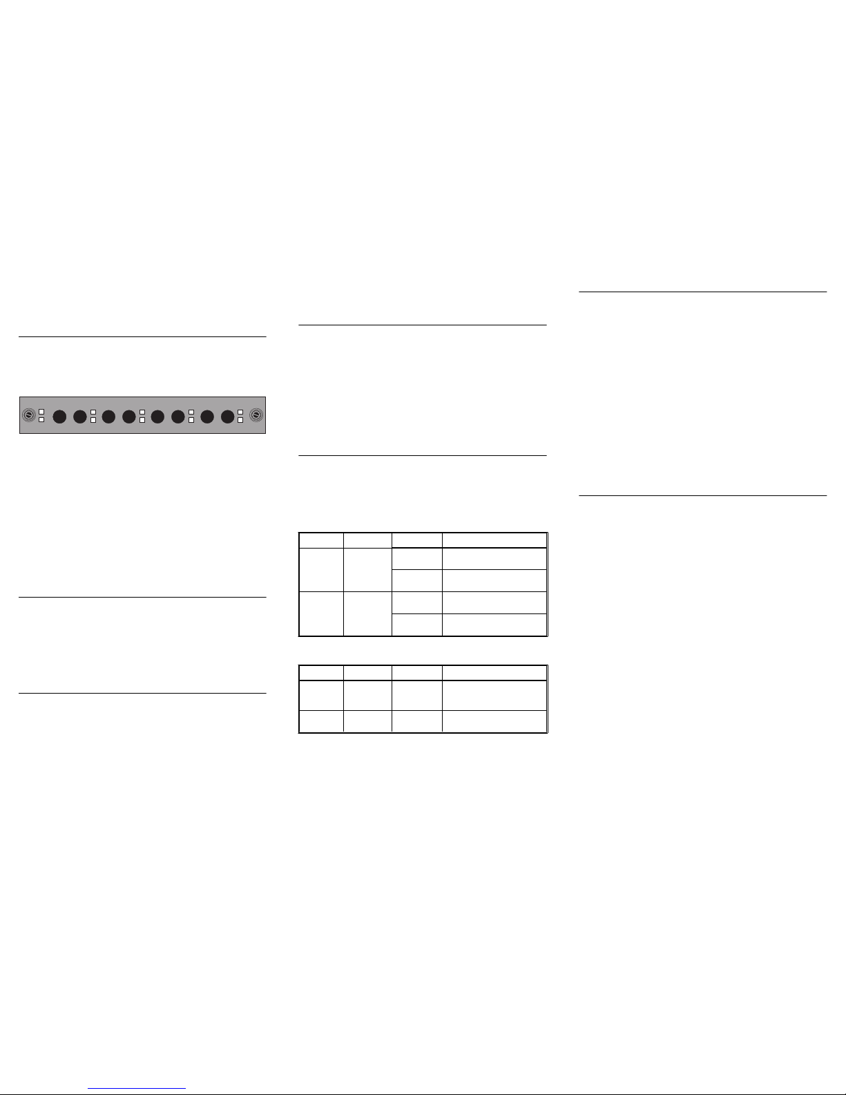
Figure 1. SmartStack SSIM-T8-04 Front Panel
The SSIM-T8-04 ports support Token Ring multimode fiber
media via dual ST-compatible optical receptacle s. Each port
provides either shared (half-duplex), 4 or 16 Mbps
connections to 802 .5j c omplia nt ports (like TRF OT-2), or fu llduplex 32 Mbps connections to another S martSta ck SSIM-T804 Interface Module. In addition to the Token-Ring
connectors , there are ten LEDs on the SSIM-T8-04 front
panel. These LEDs in dicate the operationa l stat us of the SSIMT8-04 and the ports.
SSIM-T8-04 Module Package Contents
Your interface module package contains the following items:
•
One SSIM- T8 - 0 4 Sm ar t Stack Interfac e M od u l e for th e
SmartStack Token Ring Switch
•
One SSIM- T8 -0 4 Sm ar t S ta ck Int er f ac e M od u l e
Installation Guide (this document)
Installation
1. Power off the base switch by unplugging it.
2. Remove the plate covering the expansion sl ot on the front
of the base switch by unscrewing the two retaining
thumbs c rew s. Keep th e pl at e f o r u se in th e even t th at the
interface module is ever removed.
3. Carefully insert the SSIM-T8-0 4 into the rails on ea ch side
of the expansion s lo t, s liding it back unt il the conne ctor on
the module is seated into the connector at the back of the
slot. When the SSIM-T8-04 is fully seated, its faceplate
will be flush with the fro nt of the base switch.
4. Secure the interface module with the two attached
thumbscrews.
Cabling
For backbone cabling, 62.5/125 micron, multimode optical
fiber cable that meets the ISO/IEC 11801 standard or the EIA/
TIA 568A standard, is recommended. The recommended
maximum cable length is 2000 m (1.2 mi). Eac h port is
terminated in an ST fiber connection. The correct cable
connection is Fiber Transmitter to Fiber Receiver.
The ST connectors marked TX/RX send/receive 850 nm
infrared light to an attached device.
LEDs
Table 1 lists the two status LEDs on the left front of the
interface module and their meanings. Table 2 lists the port
LEDs on the right of the interface module and their meanings.
Note:
Both status LEDs are on for several seconds after a
reset. The LEDs go off before the start of diagnostics.
Table 1. Status LEDs and their Meanings
Tab le 2. Port LEDs and their Meanings
Testing the Interface Module
1. Power on the base switch to start diagnostics. The
SmartStack Token Ring switch indicates that diagnostics
are in progress by turn ing on its DIA G L ED. After about a
minute, the interface module DIAG LED will also be
turned on.
2. Verify that the base switch diagnostics have been
completed successfully. On the SmartStack Token Ring
switch th is is indicated when its DIAG LE D is tu r ned off,
and the ERR LED stays turned of f. Diagnostics can take up
to four minutes to complete.
3. Verify that the ERR LED on the interface module is off. If
it is off, diagnosti cs ha ve bee n successf ully comp leted, and
the SSIM-T8-04 is ready for configuration.
Configuration
The SSIM-T8-04 ports can be config ured just like the base
switch ports. They wil l appear as additional ports on any
configuration panel where ports are listed. The port numbers
will begin where the numbers of the bas e switch stop.
If for example the base switch has 20 ports and an int erfa ce
module in the left front pane l slot, the module por ts will appear
after Port 20 on the various port configuration panels and be
designated 21, 22, 23 and 24. If the module is in the right front
panel slot, the ports will be designated 25, 26, 27 and 28.
Follow the instructions contained in the
SmartStack STS1620RM/STS16-20FRM Token Ring Swit ch, Installation and
User Guide
for configuring the interface module ports.
When connecting one STS16 -20RM switc h to anot her S TS1620RM switch using the SSIM-T8-04 Interface Module, one
end of the fiber connection must be manually configured as
“ADAPTER”, and the other end as “PORT”. Use the
SmartStack Token Ring Switch Port Configuration menu.
When connecting ports on the SmartStack SSIM-T8-04
Interface Module to non IEEE 802.5 j compliant devices, the
Interface Module fiber ports must be manually set to RI/RO
port mode to ensure that a connec tion can be established.
When connecting ports on the SmartStack SSIM-T8-04
Interface Module to other fiber equipment that supports FDX
(full-duplex) connections, the interface module fiber ports
1
2
TXTX RX TXRX
3
RX TX RX INS
4
ACTACTACTACT
ERR
INSINSINS
DIAG
LED Position State Meaning
DIAG
(green)
Top On Diagnostics are in
progress.
Off The interface module is
working co rrectly.
ERR
(yellow)
Bottom On A interface module
failure has occurred.
Off The interface module is
working co rrectly.
LED Position State Meaning
INS
(green)
Top On The attached de vice is
connected to th e inter face
module port.
ACT
(green)
Bottom On or
blinking
Data is being transmitted
or received by t he port.
4
must be manually set to FDX port mode to ensure t hat an FDX
connection can be established.
Note that if b o th the RI and RO of an attached device ar e
connected to a single SmartS tack Token Ring switch, or if a
series of dev ices are connected to a single SmartStack Token
Ring switch, spanning tree must be enabled.
Tr oubles hootin g
•
If you are install ing the i nterface module and the LEDs do
not come on when the base switch is powered on, verify
that the interface m odule is properly seated in the sl ot.
•
During diagnostics, the interface module DIAG LED is
on. If the ERR LED is on at any time, it indicates th at the
interface module is defe ctive and needs to be serviced.
•
Troublesho ot t he int erf ace modu le port s just l ik e the base
switch ports. Refer to the base switch documentation for
troubleshooting hi nts.
•
If you have been unable to get the interface module INS
LED to turn on after connecting a interface module port
to another device, check that you are using the correct
cable type.
Important:
Check that TX on the interfac e mo dule is
connected to RX on the remote device, and that RX is
connected to TX on the remote device.
❏
Getting in Touch With Technical Support
For additional su pport related to this device or doc ument,
contact Cabletron Sys tems using one of the following
methods
:
World Wide Web http://www.cabletron.com/
Phone (603) 332-9400
Internet mail support@cabl etron.com
FTP ftp://ftp.cabletron.com/
Login
anonymous
Password
your email address
To send comments or suggesti ons concerning this
document, contact the Cabletron Systems Technical
Writing Department via the following email
address: TechWriting@cabletron.com
Make sure to include t he document Part Number in the
email message.
SSIM-T8-04
Fiber Token Ring
SmartStack Interface Module
for
SmartStack
Token Ring Switch
Installation Guide
Trademarks
SmartStack is a trademarks of Cabletron Systems, Inc. All other brands or product names are trademarks
or registered trademarks of their respective holders.
Copyrights
Cabletron reserves the right to modify th e information g iven in this publication without prior notice. The
warranty terms and conditions applicable for your purchase of this equipment are given at the time of
purchase. Consult them for details.
All rights reserved
. No part of this publication may be reproduced, stored in a retrieval system, or
transmitted, in any form or by any means, electronic, mechanical, photocopying, recording or otherwise,
without the prior written permission of the publisher.
Publicat io n: O C- 70 56 v. 1.0, 710001 71 2
Part Number: 9032970
©
February 1999 by Cabletron Systems, Inc.
FCC Compliance
This equipment has been tested and found to comply with th e limits for a Class A d igital d evice, p ursuant
to Part 15 of the FCC Rules. These limits are designed to provide reasonable protection against harmful
interference when the equipment is operated in a commercial environment. This equipment generates,
uses and can radiate radio frequency energy and, if not installed and used in accordance with the
instruction manual, may cause harmful interference to radio communications. Operation of this
equipment in a residential area is likely to cause harmful interference in which case the user will be
required to correct the interference at his own expense.
This device complies with part 15 of the FCC Rules. Operation is subject to the following two
conditions: (1) This device may not cause harmful interference, and (2) this device must accept any
interference received, including interference that may cause undesired operation.
CLASS 1 LASER PRODUCT
*710001712*
 Loading...