

Page 1
SSIM-T5-04 Token Ring
SmartStack Interface Module
Introduction
The SmartStack SSIM-T5-04 provides four additional Token
Ring ports for the base SmartStack STS16-20RM or STS1620FRM Token Ring switc h. These ports can be configured just
like the 20 fi xed To ken Rin g port s on t he base s witch. Eac h or
all of the interface module ports can be configured (in
combination with an y of the fixe d port s on the bas e swit ch) to
be used in CrossLink connections, and configured to be
included in virtual LANs. The interface module ports support
address filters and BOOTP/TFTP, Telnet or SNMP sessions.
DIAG
ERR
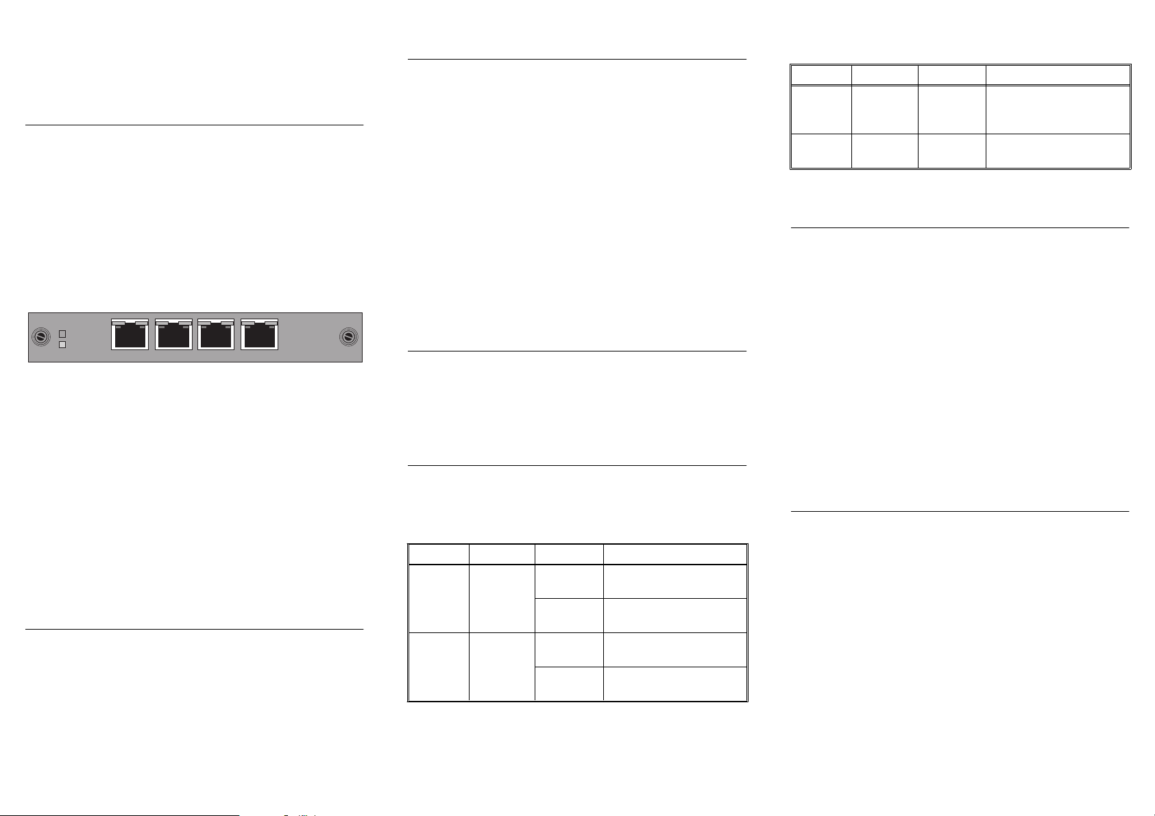
Figure 1. SSIM-T5-04 interface module Front Panel
The ports on the SSIM-T5-04 i nterface module support Toke n
Ring twisted-pa ir (UTP/STP) media via RJ-45 connectors.
The interface module ports can be confi gured j ust like th e base
switch ports to provide either shared (half-duplex) 4 or 16
Mbps Token Ring connections or dedicated (full-duplex) 32
Mbps connections.
In addition to the RJ-45 Token-Ring connectors, there are 10
LEDs on the faceplate of the in terface module (a set of two for
each port plus two for the interface module general status).
These LEDs indicate th e ope rational status of the interface
module and of the ports.
SSIM-T5-04 Module Package Contents
The interface module package contains the following items:
•
One SSI M -T5 - 0 4 Sm ar t S ta ck in t e rfa ce module fo r th e
Token Ring S w itch
•
One SSIM - T5 - 0 4 Sm art S ta ck In t erf ace Module
Installation Guide (this document)
1
234
Installation
1. Power off the base switch by unplugging it.
2. Remove the plate covering the expansion slot on the front
of the base swit ch by unscrewing the two retaining
thum b scr ew s. Keep the plat e f or use in the event th at the
interface modul e is removed.
3. Carefully insert the interface module into the rails on each
side of the expansion slot, sliding it back until the
connector on the interface module is seated into the
conne c t o r at th e ba ck of th e slot.Wh e n th e in t er f ac e
module is fully seated, the interface module faceplate will
be flush with the front of the base switch.
4. Secure the interf ac e m odule with the two attached
thumbscrews.
Cabling
For specifications and directions about cabling the UTP/STP
universal expansion modules, see Appendix B in
SmartStack
STS16-20RM/STS1 6-20FRM Token Ring Switches,
Installation and User Guide
.
LEDs
The interface module has 10 LEDs.
Table 1 lists the two status LEDs on the left front of the
interface module and their meanings.
LED Position State Meaning
DIAG
(green)
ERR
(yellow)
Table 1. Status LEDs and their meanings
Table 2 lists the port LEDs above each RJ-45 and their
meanings.
1 2 3
Top On Diagnostics are in
progress.
Off The interface module is
working correctly.
Bottom On An interface module
failur e has occurred.
Off The interface module is
working correctly.
LED Position State Meaning
INSRT
(green )
TX/RX
(green)
Table 2. Port LEDs and their Meanings
Left On The attached device is
connecte d to the in terface
module port.
Righ t O n or
blinking
Data is being transmitted
or received by the port.
Testing the interface module
1. Power on the base switch to start diagnostics. The STS1620RM Token Ring switch indicates that dia gnostics are in
progress by turning on its DIAG LED. After about a
minute, the interface module DIAG LED will also be
turned on.
2. Verify that the base switch diagnostics have been
completed su ccessfully. On the STS16-20RM, this is
indicated wh e n it s D IAG LE D is tu r ned off, and th e E R R
LED stays turned off. Diagnostics can take up to four
minutes to complete.
3. Verify that the ERR LED on the interface module is off. If
it is of f, dia gnostics h av e been succ essfully complete d, and
the interfac e module is ready for configuration.
Configuration
The interface module ports can be configured j ust lik e the base
switch ports . They will appear as additional por ts on any
configuration panel where ports are listed. The port numbers
will begin where the numb ers of the base switch stop.
If for example the base switch has 20 ports and an interface
module in the left front panel slot, the interface module ports
will appear after P ort 20 on the various port configuration
panels and be desi gnated 21, 22, 23 and 24. If t he modu le is in
the right front panel slot, the ports will be desi gnated 25, 26,
27 and 28.
Follow the instructions contained in the
20RM/STS16-20FRM Token Ring Switches, Installation and
User Guide
for configuring the interface module ports.
SmartStack STS16-
Page 2

Troubleshooting
•
If you are ins talling the inte rface modul e and the LEDs do
not come on when the base switch is powered on, verify
that the interface module is properly seate d in the slot.
•
During diagnostics, the interface module DIAG LED is
on. If the ERR LED is on at any time , it indicates that the
interface module is defective and needs to be serviced.
The individual inte rface modul e port s are like the base swit ch
ports for the purpo ses of troubleshooting. See the
STS16-20RM/STS16-20FRM Token Ring Switch, Installation
and User Guide
for troubleshooting hints.
SmartStack
Getting in Touch With Technic al Suppor t
For additi onal support related to this de vice or document,
contact Cabletron Systems using one of the following
methods
❏
:
World Wide W eb http://www.cabletron.c om/
Phone (603) 332-9400
Internet mail support@cabletron.com
FTP ftp://ftp.cabletron.com/
Login
Password
To send comments or suggestions concerning this
document, contact the Cabletron Systems Technical
Writing Department via the f ollowing email
address: TechWriting@cabletron.com
Make sure to include the document Part Number in the
email message.
anonymous
your email address
SSIM-T5-04
Token Ring
SmartStack Interface Module
for
Trademarks
SmartStack is a trademark of Cabletron Systems, Inc. All other product names are trademarks or
registered trademarks of their respective holders.
Copyrights
Cabletron reserves the right to modify th e information g iven in this publication witho ut prior notice. T he
warranty terms and conditions applicable for your purchase of this equipment are given at the time of
purchase. Please consult them for details.
All rights reserved
transmitted, in any form or by any means, electronic, mechanical, photocopying, recording or otherwise,
without the prior written permission of the publisher.
Publica t io n: OC-7055 v. 1.0, 71 00 01711
Part N umber: 9032969
Febr uary 1999 by Ca bletron Systems, Inc.
©
FCC Compliance
This equipment has been tested and found to c omply with th e limits for a Class A d igital d evice, pursu ant
to Part 15 of the FCC Rules. These limits are designed to p rovide reasonable protection against harmful
interference when the equipment is operated in a commercial environment. This equipment generates,
uses and can radiate radio frequency energy and, if not installed and used in accordance with the
instruction manual, may cause harmful interference to radio communications. Operation of this
equipment in a residential area is likely to cause harmful interference in which case the user will be
required to correct the interference at his own expense.
This device complies with part 15 of the FCC Rules. Operation is subject to the following two
conditions: (1) This device may not cause harmful interference, and (2) this device must accept any
interference received, including interference that may cause undesired operation.
Caution
The RJ-45 connectors may only be connected to SELV circuits (LAN communication).
4
. No part of this publication may be reproduced, stored in a retrieval system, or
CLASS 1 LASER PRODUCT
*710001711*
SmartStack
Token Ring Switch
Installation Guide
 Loading...