

Cabletron Systems SSIM-R2-02, SSIM-R8-02 Installation And User Manual

SSIM-R2-02/SSIM-R8-02
High Speed Token Ring
SmartStack Interface Modules
Installation
and
User Guide

Notice
Cabletron Systems reserves the right to make changes in specifications and other
information contained in this document without prior notice. The reader should in all
cases consult Cabletron Systems to d etermine whether any such chan ges have b een made.
The hardware, firmware, or software described in this manual is subject to change
without notice.
IN NO EVENT SHALL CABLETRON SYSTEMS BE LIABLE FOR ANY
INCIDENTAL, INDIRECT, SPECIAL, OR CONSEQUENTIAL DAMAGES
WHATSOEVER (INCLUDING BUT NOT LIMITED TO LOST PROFITS) ARISING
OUT OF OR RELATED TO THIS MANUAL OR THE INFORMATION CONTAINED
IN IT, EVEN IF CABLETRON SYSTEMS HAS BEEN ADVISED OF, KNOWN, OR
SHOULD HAVE KNOWN, THE POSSIBILITY OF SUCH DAMAGES.
i
© October 1999 by:
Cabletron Systems, Inc.
35 Industrial Way
Rochester, NH 03867
All Rights Reserved.
Order Number: 9032961-01
(DOC-7059 v. 1.1, 710001813)
SmartStack
CompuServe
i960 microprocessor
Ethernet
is a trademark of Cabletron Systems, Inc.
is a registered trademark of CompuServe, Inc.
is a registered trademark of Intel Corp.
is a trademark of Xerox Corporation.
Notice

ii
FCC Notice
This device complies with Part 15 of the FCC rules. Operation is subject to the following
two conditions: (1) this device may not cause harmful interference, and (2) this device
must accept any interference received, including interference that may cause undesired
operation.
NOTE:
digital device, pursuant to Part 15 of the FCC rules. These limits are designed to provide
reasonable protection against harmful interference when the equipment is operated in a
commercial environment. This equipment uses, generates, and can radiate radio
frequency ener gy and if not ins talled in accordan ce with the operator’s manual, may cause
harmful interference to radio communications. Operation of this equipment in a
residential area is likely to cause interference in which case the user will be required to
correct the interference at his own expense.
WARNING:
approved by the party responsible for compliance could void the user’s authority to
operate the equipment.
This equipment has been tested and found to comply with the limits for a Class A
Changes or modifications made to this device which are not expressly
VCCI Notice
This is a Class A product based on the standard of the Voluntary Control Council f or
Interference by Information T echnology Equipment (VCCI). If this equipment is used in a
domestic environment, radio disturbance may arise. When such trouble occurs, the user
may be required to take corrective actions.
Industry Canada Notice
This digital apparatus does not exceed the Class A limits for radio noise emissions from
digital apparatus set out in the Radio Interference Regulations of the Canadian
Department of Communications.
Le présent appareil numérique n'émet pas de bruits radioélectriques dépassant les limites
applicables aux appareils numériques de la class A prescrites dans le Règlement sur le
brouillage radioélectrique édicté par le ministère des Communications du Canada.
Notice

Declarati on of Co nformity
Addendum
iii
Application of Council Directive(s):
Manufacturer’s Name:
Manufacturer’s Address:
European Representati v e Name :
European Representative Address:
Conformance to Directive(s)/Product Standards:
Equipment Type/Environment:
89/336/EEC
73/23/EEC
Cabletron Systems, Inc.
35 Industrial Way
PO Box 5005
Rochester, NH 03867
Mr. J. Solari
Cabletron Systems Limited
Nexus House,
Newbury Business Park
London Road, Newbury
Berkshire RG13 2PZ, England
EC Directive 89/336/EEC
EC Directive 73/23/EEC
EN 55022
EN 50082-1
EN 60950
Networking Equipment, for use
in a Commercial or Light
Industrial Environment.
We the undersigned, hereby declare, under our sole responsibility, that the equipment
packaged with this notice conforms to the above directives.
Manufacturer Legal Representative in Europe
Mr . Ronald Fotino
Full Name Full Name
Principal Compliance Engineer
Title Title
Rochester, NH, USA
Location Location
Mr. J. Solari
Managing Director - E.M.E.A.
Newbu ry , Berkshire, England
Notice

iv
Notice

Table of Contents
1. Introduction 1
2. Installation 3
Package Contents . . . . . . . . . . . . . . . . . . . . . . . . . 3
Installation Procedure . . . . . . . . . . . . . . . . . . . . . . . 3
Hardware Installation . . . . . . . . . . . . . . . . . . . . . . . 4
Software Installation . . . . . . . . . . . . . . . . . . . . . . . . 6
TFTP Download . . . . . . . . . . . . . . . . . . . . . . . . 6
Serial Download . . . . . . . . . . . . . . . . . . . . . . . . 7
Cabling . . . . . . . . . . . . . . . . . . . . . . . . . . . . . . . 7
LEDs . . . . . . . . . . . . . . . . . . . . . . . . . . . . . . . . 8
Power-On Self Test . . . . . . . . . . . . . . . . . . . . . . . . 9
Configuration . . . . . . . . . . . . . . . . . . . . . . . . . . . 9
Default Configuration . . . . . . . . . . . . . . . . . . . . 10
v
3. Console Configuration 11
Introduction . . . . . . . . . . . . . . . . . . . . . . . . . . . 12
Ports, Port Groups and VLANs . . . . . . . . . . . . . . . 12
HSTR Virtual Ports and VLAN Tagging . . . . . . . . . . . 13
Virtual Port Restriction . . . . . . . . . . . . . . . . . . . . 13
Ring Number Restriction . . . . . . . . . . . . . . . . . . . 14
General Guidelines . . . . . . . . . . . . . . . . . . . . . . . 14
Navigating within the Menus . . . . . . . . . . . . . . . . . 15
Configuration Overview . . . . . . . . . . . . . . . . . . . . . 15
Port Configuration - HSTR Ports . . . . . . . . . . . . . . . . 16
Virtual Port Configuration . . . . . . . . . . . . . . . . . . . . 18
4. Statistics 21
Statistics Menu . . . . . . . . . . . . . . . . . . . . . . . . . 22
Port Status . . . . . . . . . . . . . . . . . . . . . . . . . . . . 23
Port Statistics . . . . . . . . . . . . . . . . . . . . . . . . . . 24
General Statistics . . . . . . . . . . . . . . . . . . . . . . 25
Virtual Port Statistics . . . . . . . . . . . . . . . . . . . . . 30
802.5 Statistics . . . . . . . . . . . . . . . . . . . . . . . 31
5. Getting in Touch with Technical Support 33
Problem Report Form . . . . . . . . . . . . . . . . . . . . . . 34
Appendix A. Abbreviations 37
SSIM-R2-02/SSIM-R8-02 HSTR SmartStack Interface Modules Installation and User Guide

vi
List of Figures
Figure 1. SSIM-R2-02 High-Speed Token Ring
SmartStack Interface Module . . . . . . . . . . . . . . . . . 1
Figure 2. Removing the Expansion Slot Cover . . . . . . . . . . . . . 5
Figure 3. Inserting the Module . . . . . . . . . . . . . . . . . . . . . . 5
List of Tables
Table 1. LEDs at the Left on the Front Panel . . . . . . . . . . . . . . 8
Table 2. LEDs at the Right of Every Port . . . . . . . . . . . . . . . . 9
Table 3. HSTR Port Configuration: Status Values. . . . . . . . . . . . 16
Table 4. Virtual Port Configuration: Status Values. . . . . . . . . . . . 18
Table 5. Virtual Port Configuration: Maximum Frame Size . . . . . . . 19
Table 6. Config Loss Values. . . . . . . . . . . . . . . . . . . . . . . 26
SSIM-R2-02/SSIM-R8-02 HSTR SmartStack Interface Modules Installation and User Guide
1. Introduction
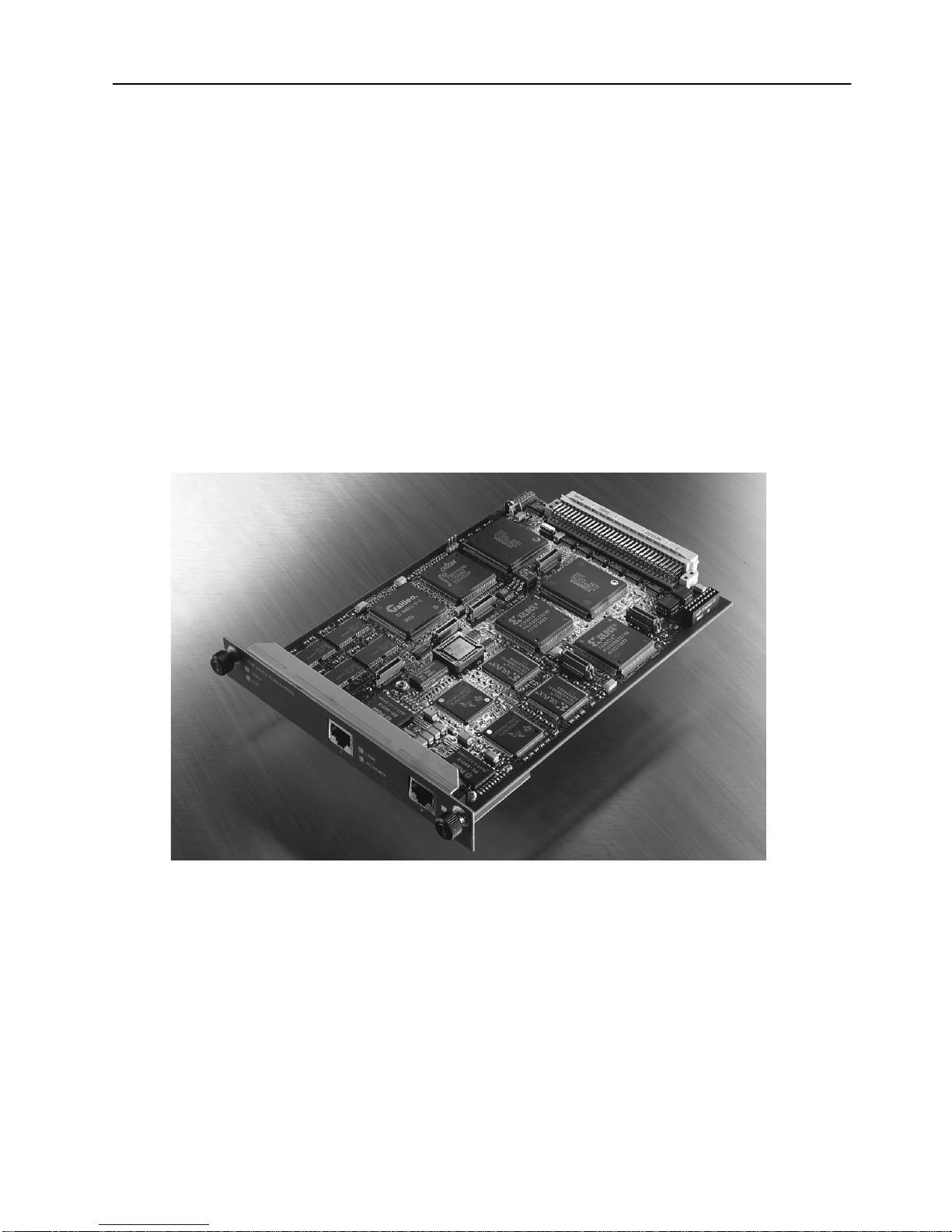
The SmartStack SSIM-R2-02 and SmartStack SSIM-R8-02 provide two ports of
100 Mbps High-Speed Token Ring for the SmartStack STS16-20RM Token Ring
switch. Designed for high performance and low latency, these modules provide
seamless integration between legacy Token Ring n etworks and HSTR servers or an
HSTR backbone.
1
➽
Note:
The SSIM-R2-02 offers UTP-5 copper connections with RJ-45 interface
connectors. The SSIM-R8-02 offers multimode optical fiber connections with
VF-45 interface connectors.You can mount either of them in one of the two frontpanel expansion slots on the STS16-20RM switch.
References to STS16-20RM are also applicable to STS16-20FRM.
Figure 1. SSIM-R2-02 High-Speed Token Ring
SmartStack Interface Module
Introduction SSIM-R2-02/SSIM-R8-02 HSTR SmartStack Interface Modules Installation and User Guide

2
The SSIM-R2-02 and SSIM-R8-02 conform to the IEEE 802.5t standard for 100
Mbps High-Speed Token Ring, and implement the standard DTR MAC protocol.
An HSTR port can connect to a standard HSTR adapter or it can act as a trunk port
and carry traffic from up to 63 VLANs configured in the switch. This is achieved
using standard IEEE 802.1Q VLAN frame tagging. For each VLAN a virtual port
is created that behaves much like an ordinary Token Ring port.
The module enables standard Token Ring source routing and supports all the
switching modes implemented in the switch.
Six LEDs on the front panel indicate the overall operational state of the module and
the two ports. Configuration and detailed status in f orm ation is available from the
switch console or from the graphical management application.
❏
SSIM-R2-02/SSIM-R8-02 HSTR SmartStack Interface Modules Installation and User Guide Introduction

2. Installation
This chapter describes how to install, connect, and start using the SSIM-R2-02 or
SSIM-R8-02. The following main topics are covered:
Package Contents
•
Installation Procedure
•
Hardware Installation
•
Software Installation
•
Cabling
•
LEDs
•
Power-On Self Test
•
Configuration
•
3
Package Cont e n t s
Your SSIM-Rx-02 package contains the following items:
One SmartStack SSIM-R2-02 High-Speed Token Ring SSIM (UTP)
•
OR
one SmartStack SSIM-R8-02 High-Speed Token Ring SSIM (MMF)
One
•
SSIM-R2-02/SSIM-R8-02 High-Speed Token Ring SmartStack Interface
Module Guide to Operations
Installation Procedure
The SSIM-R2-02 and SSIM-R8-02 are packaged with software for both the module
itself and the SmartStack Token Ring switch. The switch is also supplied with both
software images. To ensure compatibility between the module and the switch,
install the latest of the software versions.
The software for the switch and the module is also available via Cabletron ’s online
services (Internet, FTP).
.
(this manual).
Install the module, as follows:
1. Install the software in the SmartStack Token Ring switch. See the switch
manual for instructions on downloading the software.
2. Optional: Clear the NVRAM in the base switch. This will erase all
configuration in the switch.
Installation SSIM-R2-02/SSIM-R8-02 HSTR SmartStack Interface Modules Installation and User Guide

4
3. Reset the switch to activate the new software.
4. If you cleared NVRAM in step 2, re-establish the switch configuration. Verify
that the switch is operating correctly.
5. Power off the switch
➽
Warning:
Be sure to install a version of the base switch software that supports the
SSIM-Rx-02 (version 3 .00 or later)
Otherwise, the switch will not recognize it and this may in some cases corrupt the
configuration.
6. Physically install the SSIM-Rx-02 in one of the two expansion slots. See section
“Hardware Installation” on page 4 for detailed instructions.
7. Power on the switch.
8. Download the software for the SSIM-Rx-02. See section “Software
Installation” on page 6 for detailed instructions.
9. If you plan to use the graphical switch manager application, install it now.
10.If necessary, conf igure the module. F or details, see the section “Configuration”
on page 9 as well as Chapter 3
Hardware Installation
To install the SSIM-R2-02 and SSIM-R8-02 in a SmartStack STS16-20RM or
STS16-20FRM switch:
before ph y sically inserting the
Console Configuration”.
, “
SSIM-Rx-02.
1. Power o ff t he base swi tch b y unpluggi ng the po wer cord from the po wer ou tlet.
If the switch uses the optional SmartStack STS-PSU Redundant Power Supply
Unit, unplug the connector from the base switch as well.
2. Select an empty expansion module slot in which to instal l the SSIM-Rx-02 . You
can install the module in either or both of the slots.
3. Loosen the two screws on the expansion slot cover plate and remove the cover
See Figure 2. Keep the plate for use in the event that the expansion module is
later removed.
SSIM-R2-02/SSIM-R8-02 HSTR SmartStack Interface Modules Installation and User Guide Installation
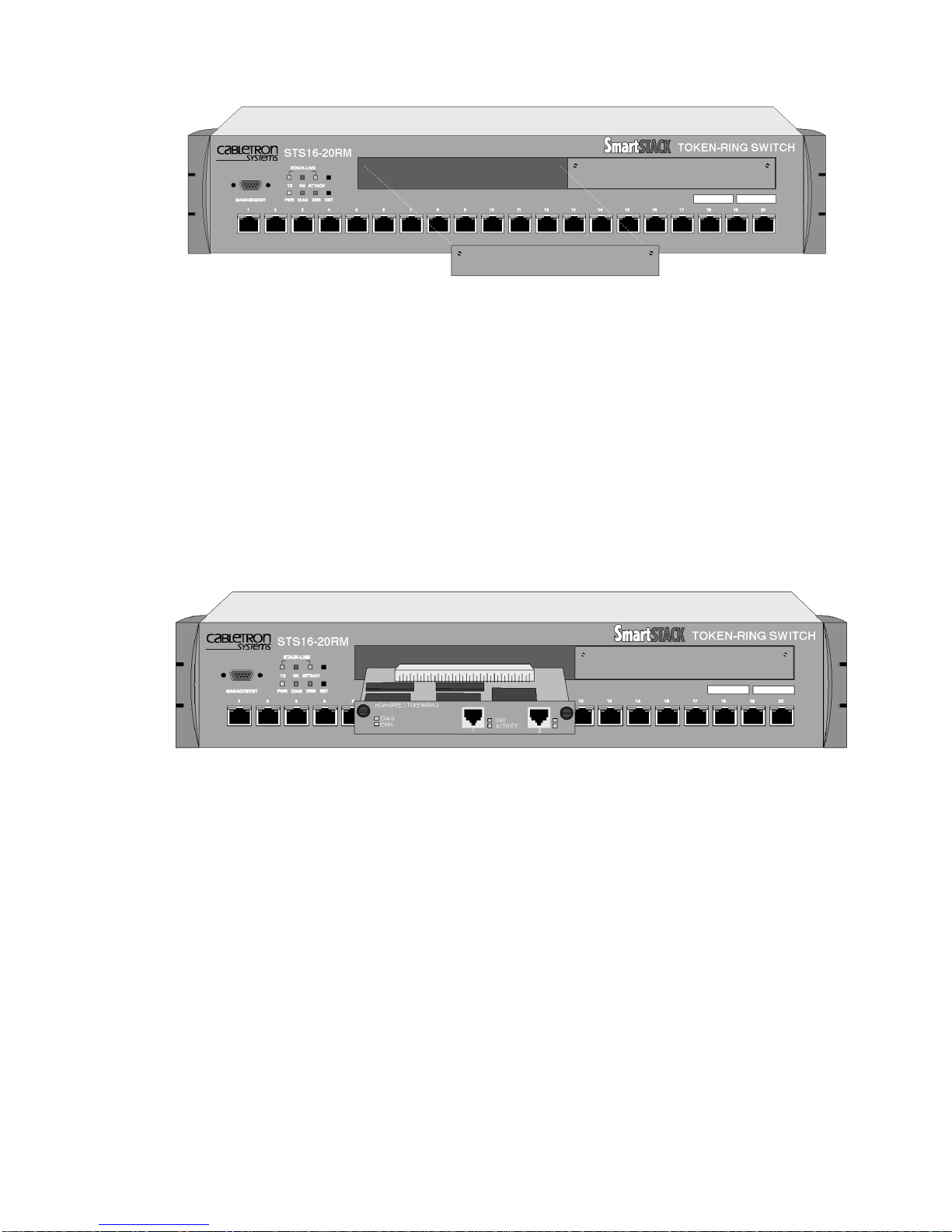
Figure 2. Removing the Expansion Slot Cover
5
➽
Warning:
Expansion modules are not hot-swappable. If you install or remove
expansion modules while the power to the switch is on, damage may occur to the
switch and to the module.
4. Carefully insert the SSIM-Rx-02 into the rails on each side of the expansion
slot, and slide the module back until the connector on the module is seated into
the connector at the back of the slot. See Figure 3. When the module is fully
seated, the module faceplate will be flush with the front of the base switch.
Figure 3. Inserting the Module
5. Secure the SSIM-Rx-02 with the two attached thumb screws.
6. Reapply power to the switch.
Installation SSIM-R2-02/SSIM-R8-02 HSTR SmartStack Interface Modules Installation and User Guide
6
Software Installation
Before you can use your SSIM-Rx-02, you must install the SSIM-Rx-02 software
image which you can download to the SSIM-Rx-02 via TFTP or via a serial line.
TFTP Download
1. On the disks supplied with the module, find the image file. The file name is of
the form
example
2. Copy the software image file to a directory on the TFTP server.
HSTRyyzz.BIN
HSTR400.BIN
where yyzz is the version number of the softw are. For
is version
of the software image.
4.00
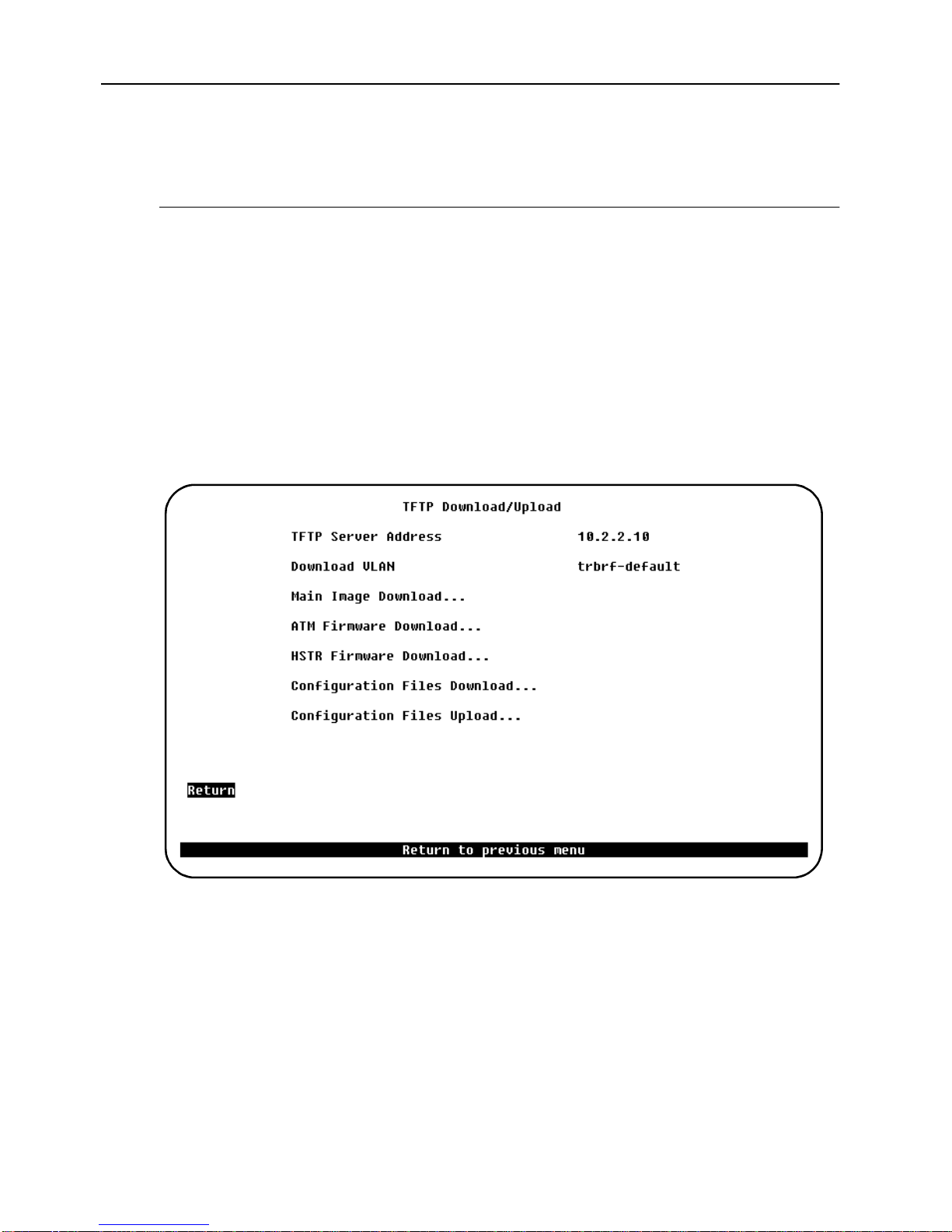
3. On the main menu in the console, select
Download/Upload
4. Select
Upload
TFTP Download/Upload
menu:
menu.
to display the
Download/Upload
TFTP Download/
to display th e
5. On this menu, set the IP address of the TFTP server. Also, set the download
VLAN (the BRF on which the TFTP server is located).
6. Select
HSTR Firmware Download
TFTP Download
7. Select
HSTR Firmware Download Filename
the software image to download.
8. Select
Execute HSTR Image Network Download
download.
While the software is transferred over the network, the console will d isp lay
SSIM-R2-02/SSIM-R8-02 HSTR SmartStack Interface Modules Installation and User Guide Installation
screen.
to display the
HSTR Firmware
and type the f ilenam e of
to start the

messages describing download activity. When the software has been transferred,
you will see the following messages:
Network download compl ete. Now transferrin g to HSTR
Module(s), please wait ...
Download of HSTR firmw are complete – HSTR m odule(s)
being reinitialized...
The software image is then programmed into the nonvolatile memory on the SSIMRx-02. When software installation is complete, the module starts for normal
operation, and the following message is displayed:
Press <RETURN> to cont inue...
Serial Download
1. On the discs supplied with the module, find the software image file. The file
name is of the form
software . For exampl e
HSTRyyzz.BIN
HSTR0310.BIN
Copy the software image file to a directory on the TFTP server.
where yyzz is the version number of the
is version
of the software image.
3.10
7
2. From the main menu, select
Upload
3. Select
is displayed.
4. Select
5. Using your terminal software, transfer the software image to the module with
the X-Modem protocol. The transfer will take some minutes depending on your
terminal emulator baud rate.
The software image is then programmed into the FLASH memory of the module,
and will remain there until it is replaced. When the software installation is
complete, the module is started for normal operation, and the following message is
displayed:
Cabling
Download/Upload
menu.
Serial Link Download
HSTR Firmware Download
. The
Serial Link Download
.
Press <RETURN> to cont inue...
to disp lay t he
Download/
screen
The cabling required depends on the v ersion of the SSIM-Rx- 02 you are ins talling.
SmartStack SSIM-R2-02 2-port High-Speed Token Ring SSIM (UTP5)
The UTP module uses standard UTP Category 5 copper cables. The maximum
cable length is 100 m (328 feet).
Installation SSIM-R2-02/SSIM-R8-02 HSTR SmartStack Interface Modules Installation and User Guide

8
1. Insert the modular RJ-45 jack from eithe r end o f a standard UTP-5 cable inton
one of the connectors on the SSIM-R2-02 front panel.
2. Connect the other end of the cable to either another HSTR switch port (for
example, another module) or an HSTR adapter.
3. If the defaul t
appropriate
Port
port mode is in effect, the port will automatically open in the
Auto
or
Station
mode. Refer to Chapter 3, “Console Configuratio n”
for details on port mode configuration.
The SSIM-R2-02 also supports IBM type 1 STP copper cables (150 Ohm), which
have a maximum length of 100m (328 feet). To use an STP cable, then balluns with
an RJ-45 connector are required.
SmartStack SSIM-R8-02 2-port High-Speed Token Ring SSIM (MMF)
The MMF module uses multimode 62.5/ 12 5 micron fi ber cables with a maxi mu m
cable length of 2000 m (6560 feet).
1. Connect a VF-45 optic fiber to the VF-45 connector on the front panel of the
SSIM-R2-02. To ensure a proper connection, it may be necessary to clean the
fiber connectors with a soft tissue dipped in alcohol.
2. Connect the other end of the cable to either another HSTR switch port (for
example, another SSIM-Rx-02) or an HSTR adapter.
3. If the defaul t
LEDs
There are six LEDs on the front panel of the SSIM-Rx-02. During normal
operation, the two LEDs on the left side of the front panel indicate the module
status:
port mode is in effect, the port will automatically open in the
Auto
appropriate
Port
or
Station
mode. Refer to Chapter 3, “Console Configuratio n”
for details on port mode configuration.
LED Position State Meaning
DIAG (green) Top On Diagnostics are in process.
Off No diagnostics are in process.
ERR (yellow) Botto m On A module failure has occurred.
Off The module is working correctly.
Table 1. LEDs at the Left on the Front Panel
SSIM-R2-02/SSIM-R8-02 HSTR SmartStack Interface Modules Installation and User Guide Installation
 Loading...