

Cabletron Systems SSIM-A2-01, SSIM-A8-01 Installation And User Manual

SSIM-A2-01/SSIM-A8-01
ATM 155
SmartStack Interface Modules
Installation
and
User Guide

NOTICE
Cabletron Systems reserves the righ t to ma ke ch anges in specifications and other informat ion contained in this
document without prior notice. The rea de r should in all cases consult Cab le tro n Systems to determine whet her
any such changes have been made .
The hardware, firmware, or software describe d in thi s ma nua l is sub je ct to c ha nge w ithout notice.
IN NO EVENT SHALL CABLETRON SYSTEMS BE LIABLE FOR ANY INCIDENTAL, INDIRECT,
SPECIAL, OR CONSEQUENTIAL DAMAGES WHATSOEVER (INCLUDING BUT NOT LIMITED TO
LOST PROFITS) ARISING OUT OF OR RELATED TO THIS MANUAL OR THE INFORMATION
CONTAINED IN IT, EVEN IF CABLETRON SYSTEMS HAS BEEN ADVISED OF, KNOWN, OR
SHOULD HAVE KNOWN, THE POSSIBILITY OF SUCH DAMAGES.
1999 by Cabletron Systems, Inc., P.O. Box 5005, Rochester, NH 03866-5005
All Rights Re served
Printed in the United States of America
Order Number: 9032990-01 October 1999
(OC-7062 v.1.1, 710001815)
i
Cabletron Systems, SPECTRUM, LANVIEW
SmartSwitch
All other product na m es m ent i oned in this manual may be trademarks or registered trademarks of their
respective companies.
SmartStack
and
are trademarks of Cabletron Sys tems, Inc.
MicroMMAC
, and
are regist ered trademarks and
FCC NOTICE
This device complies with Part 15 of the FCC rules. Operation is subject to the following two conditions: (1)
this device may not cause harmful interference, and (2) this device must accept any interference received,
including interference that may cause undesired operation.
NOTE:
pursuant to Part 15 of the FCC rules. These limits are designed to provide reasonable protection against harmful
interference when the equipmen t is operated in a commercial environment. This equipme nt uses, generates , and
can radiate radio fre quency energy and if not installed in a cc ordance with the operator’s manual , m ay cau s e
harmful interfe re nce to radio communic ations. Operation of th is equipment in a reside nti al area is likely to
cause interference in which case the user will be required to correct the interfer ence at his own expense.
WARNING:
responsib le f or compliance could void the user’s authority to operate the equipm ent.
This equipment has been tested and foun d to c omply with the limit s f or a Cl ass A digital device,
Changes or modifications made to this device whi ch are not expressly appr oved by the party
Notice

ii
INDUSTRY CANADA NOTICE
This digital a pparatu s does n ot e xcee d the C lass A li mits f or ra dio noi se e missions f rom d igital app aratus s et out
in the Radio Interfere nce Regulations of the Canadi an Department of Comm unications.
Le présent appareil num érique n’émet pas de bru its radi oélectriques dépassant les limit es ap plicables aux
appareils numériqu es de la class A pr esc rit es da ns le Rè gle m ent sur le brouillage radioélec tr ique édicté par le
ministère des Communications du Canad a.
VCCI NOTICE
This is a Class A product based on the standard of the Voluntary Control Council for Interference by
Information Technology Equipment (VCCI). If this equipment is used in a domestic environment, radio
disturbance may arise. When such trouble occurs, the user may be required to take corrective actions.
CABLETRON SYSTEMS, INC. PROGRAM LICENSE AGREEMENT
IMPORTANT:
This document is an agreement betwe en yo u, the end user, and Cabletron Systems, Inc. (“Ca ble tron”) that sets
forth your rights and obli gat i ons w it h re spect to the Cabletron software program (the “Program” ) contained in
this package. The Program may be contained in firmware, chip s or ot her media. BY UTIL IZ IN G TH E
ENCLOSED PRODUCT, YOU ARE AGREEING TO BECOME BOUND BY THE TERMS OF THIS
AGREEMENT, WHICH INCLUDES THE LICENSE AND THE LIMITATION OF WARRANTY AND
DISCLA I M ER OF LIABI LITY. IF YOU D O NOT AGREE TO THE TERMS O F TH IS AGREEMENT,
PROMPTLY RETURN THE UNUSED PRODUCT TO THE PLACE OF PURCHASE FOR A FULL
REFUND.
Before utilizing this product, careful ly re a d thi s Li ce nse Agreement.
Notice

iii
CABLETRON SOFTWARE PROGRAM LICENSE
1. LICENSE. You have the right to use only the one (1) copy of the Program provided in this package subject
to the terms and con ditions of th is License Ag r eement.
You may not copy , reproduce or transmit any part of the Program except as permitted by the Copyright Act
of the United States or as authorized in writing by Cabletron.
2. OTHER RESTRICTION S
3. APPLICABLE LAW
state and federal courts of New Hampshire . Yo u ac c ept the personal jurisdiction and venu e of the New
Hampshire courts.
. You may not reverse engineer, decompile, or disassem ble the Program.
. This License Agreement shall be interpreted and governed under the laws and in the
EXCLUSION OF WARRANTY AND DISCLAIMER OF LIABILITY
1. EXCLUSION OF WARRANTY. Except as may be specifically provided by Cabletron in wr it in g,
Cabletron makes no warranty, expressed or implied, concerning the Program (including its documentation
and media).
CABLETRON DISCLAIMS ALL WARRANTIES, OTHER THAN THOSE SUPPLIED TO YOU BY
CABLETRON I N WRITING, EI THER EXPRESSED OR IM PLIED, INCLUDING B UT NO T LIMI TED
TO IMPLIED WARRANTIES OF MERCHANTABILITY AND FITNESS FOR A PARTICULAR
PURPOSE, WITH RESPECT TO THE PROGRAM, THE ACCOMPANYING WRITTEN MA T ERIALS,
AND ANY ACCOMPANYING HARDWARE.
2. NO LIABILITY FOR CONSEQUENTIAL DAMA GES
SUPPLIERS BE LIABLE FOR ANY DAMAGES WHATSOEVER (INCLUDING, WITHOUT
LIMITATION, DAMAGES FOR LOSS OF BUSINESS, PROFITS, BUSINESS INTERRUPTION, LOSS
OF BUSINESS INFORMATION, SPECIAL, INCIDENTAL, CONSEQUENTIAL, OR RELIANCE
DAMAGES, OR OTHER LOSS) ARISING OUT OF THE USE OR INABILITY TO USE THIS
CABLETRON PRODUCT, EVEN IF CABLETRON HAS BEEN ADVISED OF THE POSSIBILITY OF
SUCH DAMAGES. BECAUSE SOME STATES DO NOT ALLOW THE EXCLUSION OR
LIMITATION OF LIABILITY FOR CONSEQUENTIAL OR INCIDENTAL DAMAGES, OR ON THE
DURATION OR LIMITATION OF IMPLIED WARRANTIES, IN SOME INSTANCES THE ABOVE
LIMITATIONS AND EXCLUSIONS MAY NOT APPLY TO YOU.
. IN NO EVENT SHALL CABLETRON OR ITS
UNITED STATES GOVERNMENT RESTRICTED RIGHTS
The enclosed product (a) was developed sol ely at private expense; (b) cont ai ns “restricted computer software ”
submitted with restrict ed rights in accordance wit h Sec tion 52227-19 (a) through (d) of the Commercial
Computer Software - Restricted Rights Clause and its successors, and (c) in all respects is proprietary data
belonging to Cabletron and/or its suppliers.
For Department of Defense uni ts, the product is licensed with “Restri ct e d Ri ghts” as defined in the DoD
Supplement to the Federal Acquisition Regulations, Section 52.227-7013 (c) (1) (ii) and its successors, and use,
duplication, disclosure by the Government is subject to restrictions as set forth in subparagraph (c) (1) (ii) of the
Rights in Technical Data and Computer Software clause at 252.227-7013. Cabletron Systems, Inc., 35 Industrial
Way, Rochester, New Hampshire 03 867-0505.
Notice

iv
DECLARATION OF CONFORMITY
Application of Council Dire ctive(s):
Manufacturer’s Name:
Manufacturer’s Address:
European Representative Name:
European Representative Address:
Conformance to Directive(s)/Product Standards:
Equipment Type/Environment:
89/336/EEC
73/23/EEC
Cabletron Systems, Inc.
35 Industrial Way
PO Box 5005
Rochester, NH 03867
Mr. J. Solari
Cabletron Systems Limi ted
Nexus House, Newbury Business Park
London Road, Newbury
Berkshire RG13 2PZ, England
EC Directive 89/336/EE C
EC Directive 73/23/EEC
EN 55022
EN 50082-1
EN 60950
Networking Equipment, for use in a Commercial
or Light Industrial Environment.
We the undersigned, hereby declare, under our sole responsibili ty, that the equi pment packaged w i th t his
notice conforms to the above direct ives.
Manufacturer Legal Representative in Europe
Mr. Ronald Fotino Mr. J. Solari
___________________________________ ___________________________________
Full Name Full Name
Principal Compliance Engineer Managing Director - E.M.E.A.
___________________________________ ___________________________________
Title Title
Rochester, NH, USA Newbury, Berkshire, England
___________________________________ ___________________________________
Location Location
Notice

Table of Contents
1. Introduction 1
2. Installation 3
Package Contents . . . . . . . . . . . . . . . . . . . . . . . . . 3
Rules to Remember . . . . . . . . . . . . . . . . . . . . . . . . 4
Frame Length Limit. . . . . . . . . . . . . . . . . . . . . . . 4
One VAP per Uplink per VLAN. . . . . . . . . . . . . . . . . 5
Spanning Tree . . . . . . . . . . . . . . . . . . . . . . . . . 6
Configuration Data . . . . . . . . . . . . . . . . . . . . . . . 6
Installation Procedure . . . . . . . . . . . . . . . . . . . . . . . 7
Hardware Installation. . . . . . . . . . . . . . . . . . . . . . . . 8
Software Installation . . . . . . . . . . . . . . . . . . . . . . . . 9
TFTP Download . . . . . . . . . . . . . . . . . . . . . . . . 9
Serial Download . . . . . . . . . . . . . . . . . . . . . . . 10
Cabling . . . . . . . . . . . . . . . . . . . . . . . . . . . . . . 11
LEDs . . . . . . . . . . . . . . . . . . . . . . . . . . . . . . . 12
Testing the Module . . . . . . . . . . . . . . . . . . . . . . . . 13
Configuration . . . . . . . . . . . . . . . . . . . . . . . . . . . 14
Default Configuration. . . . . . . . . . . . . . . . . . . . . 14
v
3. Console Configuration 15
Introduction. . . . . . . . . . . . . . . . . . . . . . . . . . . . 16
General Guidelines. . . . . . . . . . . . . . . . . . . . . . . . 16
Navigating within the Menus . . . . . . . . . . . . . . . . . 17
ATM Configuration - Port Menu . . . . . . . . . . . . . . . . . 18
ATM Network Configuration . . . . . . . . . . . . . . . . . 19
ATM Network Advanced Parameters . . . . . . . . . . . . 22
ATM LEC Main Configuration Screen . . . . . . . . . . . . 26
Traffic Profiles . . . . . . . . . . . . . . . . . . . . . . . . . . 29
Traffic Profile Mapping Configuration . . . . . . . . . . . . 31
ATM LANE Parameters Configuration . . . . . . . . . . . . 32
ATM LEC PVC Configuration . . . . . . . . . . . . . . . . 37
ATM Traffic Profile Configuration. . . . . . . . . . . . . . . 38
4. Statistics 41
Statistics Menu . . . . . . . . . . . . . . . . . . . . . . . . 42
Port Status . . . . . . . . . . . . . . . . . . . . . . . . . . 43
Port Statistics. . . . . . . . . . . . . . . . . . . . . . . . . 44
General ATM Statistics. . . . . . . . . . . . . . . . . . . . 45
LEC Statistics . . . . . . . . . . . . . . . . . . . . . . . . 47
SmartStack SSIM-A2-01/SSIM-A8-01

vi
Frame-Forwarding Statistics. . . . . . . . . . . . . . . . . .48
LANE Status . . . . . . . . . . . . . . . . . . . . . . . . . . 52
Server VCC Table . . . . . . . . . . . . . . . . . . . . . . . 55
LE-ARP Table . . . . . . . . . . . . . . . . . . . . . . . . . 56
Route Descriptor Table . . . . . . . . . . . . . . . . . . . . 57
LEC VCC Statistics . . . . . . . . . . . . . . . . . . . . . . 58
VCC Statistics . . . . . . . . . . . . . . . . . . . . . . . . . 59
5. Getting in Touch with Technical Support 61
Appendix A. Abbreviations 63
Appendix B. Log Messages 65
SmartStack SSIM-A2-01/SSIM-A8-01

List of Figures
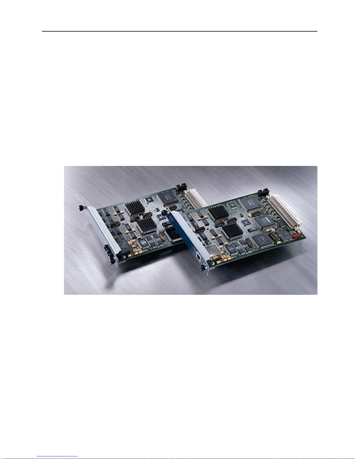
Figure 1. SSIM-A2-01 Uplink (right) and SSIM-A8-01 Uplink (left). . . . 1
Figure 2. Unsupported Configuration . . . . . . . . . . . . . . . . . . 5
Figure 3. Connecting One Switch to Two VAPs . . . . . . . . . . . . . 5
Figure 4. Connecting VLANs to ATM. . . . . . . . . . . . . . . . . . . 6
Figure 5. Removing the Expansion Slot Cover. . . . . . . . . . . . . . 8
Figure 6. Installing the SSIM-Ax-01 Module . . . . . . . . . . . . . . . 8
Figure 7. Contacting LAN Emulation Services . . . . . . . . . . . . . 33
List of Tables
Table 1. Maximum Frame Sizes . . . . . . . . . . . . . . . . . . . . . 4
Table 2. Status LEDs and their Meanings . . . . . . . . . . . . . . . 12
Table 3. ATM Interface LEDs and their Meanings . . . . . . . . . . . 12
Table 4. Normal LED State. . . . . . . . . . . . . . . . . . . . . . . 13
vii
SmartStack SSIM-A2-01/SSIM-A8-01

viii
Summary of Contents
Following is a s hort description of th e content of the chapters an d appendixes in this
publication:
Chapter 1, “Introduction”
155 Uplink UTP5 module and the SSIM-A8-01 ATM 155 Uplink MMF module.
Chapter 2, “Installation”
explains module installati on and cabli ng, des cri bes the fron t panel LEDs, and
explains configuration and testing of the module.
Chapter 3, “Console Configuration”
SSIM-Ax-01 module using a direct console connection.
Chapter 4, “Statistics”
SSIM-Ax-01 module.
Chapter 5, “Getting in Touch wit h Technical Support”
Systems’s support services such as hotline support, fax support and the support
web, as well as other services such as the bulletin board service, FTP server and
e-mail.
Appendix A, “Abbreviations”
publication.
Appendix B, “Log Messages”
SSIM-Ax-01 module.
, is a general introduction to the SSIM-A2-01 ATM
, lists the SSIM-Ax-01 module package contents,
, deals with setting up and configuring the
, lists and explains the statistics that are available for the
, lists Cabletron
contains a list of the abbreviations used in this
lists possible error messages for the
❏
SmartStack SSIM-A2-01/SSIM-A8-01
1. Introduction
The SmartStack SSIM-A2-01 and SmartStack SSIM-A8-01 ATM 155 Uplink
Modules from Cabletron Systems provide high-speed connections to the ATM
backbone for the STS16-20RM Token-Ring Switch. Designed for high
performance and low latency, these modules provide connectivity between ex isting
legacy Token Ring networks and ATM networks.
Note: References to STS16-20RM are also applicable to STS16-20FRM.
The SSIM-Ax-01 module mou nt s in one of the two fron t- panel expansion module
slots on the switch. The SmartStack SSIM-A2-01 has a UTP-5 copper shielded
RJ-45 connector interface. The SmartStack SSIM-A8-01 is available for
multimode optical fiber with duplex SC connector.
1
Figure 1.
The modules support Token Ring LAN Emulation (LANE) 1.0, UNI 3.0/3.1/4.0
and Integrated Local Management Interface (ILMI) 4.0.
A single ATM interface can emulate up to 63 Virtual ATM Ports (VAPs), each
implementing a separate LANE bridge (LANE proxy client). Virtual ATM ports
support nearly all of the features of standard Token Ring ports, and are co nfigured
just like any other Token Ring port. Extra configuration options are available for
configuring the LAN emulation and ATM interface options.
The bandwidth of the ATM interface is shared among multiple VAPs.
Additionally, advanced traffic configuration facilities eliminate transmit overloads
and permit the optimization of bandwidth usage.
SmartStack SSIM-A2-01/SSIM-A8-01 Introduction
SSIM-A2-01
Uplink (right) and
SSIM-A8-01
Uplink (left)
❏

2
SmartStack SSIM-A2-01/SSIM-A8-01 Introduction

2. Installation
This chapter contains instructions for installing, connecting and testing the SSIMAx-01 m odule.
This chapter contains the following information:
Package Contents
•
Rules to Remember
•
Installation Procedure
•
Hardware Installation
•
Software Installation
•
Cabling
•
LEDs
•
3
Tes tin g the Module
•
Configuration
•
Package Cont e n t s
Your SSIM-Ax-01 package contains the following items:
One SSIM-A2-01 ATM 155 Uplink UTP5
•
One SSIM-A8-01 ATM 155 Uplink MMF
One CD-ROM containing the Token Ring switch programs and the Switch
•
Manager for Windows and HP OpenView for Windows as well as user
documentation in pdf format.
One
•
SSIM-A2-01/SSIM -A8-01 A TM 155 Uplin k—Installati on and User Guide
(this document)
or
SmartStack SSIM-A2-01/SSIM-A8-01 Installation

4
Rules to Remember
This section will help you understand the configuration restrictions for the SSIMAx-01 ATM 155 Uplink Module. In brief, y ou mus t rememb er the fol lowing r ules
when planning to install the uplink:
Only one VAP per uplink per VLAN
•
If you create parallel paths directly between switches, spanning tree must be
•
enabled
Configuration data follows the switch slot, not the uplink module
•
Frame Length Limit
When attaching to an ATM network with LANE, possible ATM frame sizes are
1516, 4544, 9234 and 18190 bytes.
The LANE frame size (
LANE overhead, but without the 4 bytes Token Ring CRC. This gives the
following relationship to the size of frames any “real” Token Ring station should
be usin g.
TR-LANE Max
Data Frame Size
1516 1514
4544 4542
Table 1. Maximum Frame Sizes
You must configure yo ur To ken R i ng st at ions to a maxi mu m frame s ize as ab ove,
or to a lower value. Some protocols will negotiate frame sizes end-to - e nd, so me
will only recognize frame size settings between end-stations, and yet others will
only use the frame size of the transmitting interface. If you configure the frame size
of all Token-Ring stations, all protocols will work.
ATM Forum: C3
T oken-Ring Max
Frame Size
) is defined as including the two byte ATM
SmartStack SSIM-A2-01/SSIM-A8-01 Installation
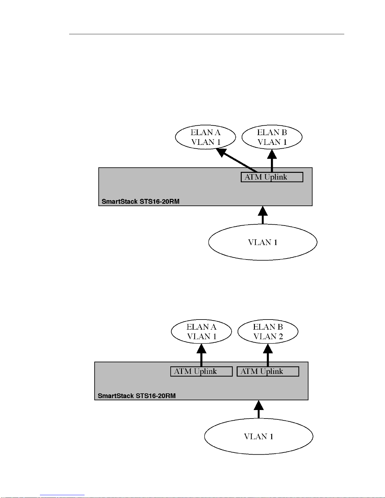
One VAP per Uplink per VLAN
The SSIM-Ax-01 module does not allow configurations in which the following
frame operations take place within a single uplink module:
Bridging from ATM back to ATM.
•
Broadcasting a frame from Token Ring to more than one ATM ELAN.
•
These operations would occur if the uplink module provided more than one VAP
per VLAN. Therefore, the configuration shown in Figure 2 is
supported.
not
5
Figure 2. Unsupported Configuration
If you want to connect the same STS16-20RM Token Ring Switch to ATM via
more than one VAP, the VAPs must reside on different ATM uplink modules, as
shown in Figure 3.
Figure 3. Connecting One Switch to Two VAPs
SmartStack SSIM-A2-01/SSIM-A8-01 Installation
6
If you connect to the same ATM ELAN more than once from the same VLAN, you
are using parallel bridges. When doing so, you must always enable the Spanning
Tree function for all the CRFs that have parallel pat hs.
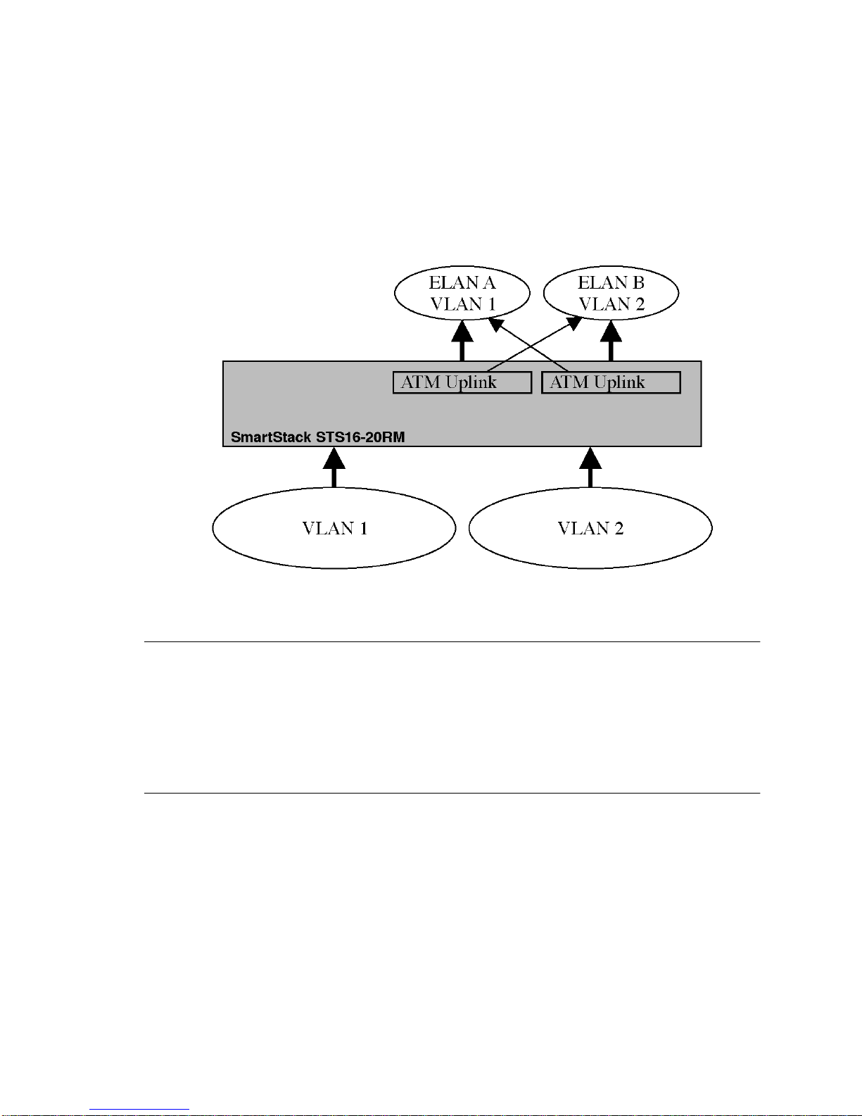
With more than one uplink, you can connect more VLANs to ATM while at that
same time creating back up connections. Figure 4 s hows two uplink modules, each
connected to two ATM ELANs. The lighter arrow shows the parallel path in the
spanning tree “blocked” state (the path is on “standby”).
Figure 4. Connecting VLANs to ATM
Spanning Tree
If you create parallel paths in your network topology, but fail to enable the spanning
tree protocol, you risk “b road cast sto rms” th at can d isrupt you r en tire n etwork . To
enable spanning tree, see section “Spanning Tree Menu” in the STS16-20RM
switch manual. The default setting for spanning tree is disabled.
Configuration Data
When you configure an uplink module in a switch, the configuration data is applied
to any uplink in that particular switch slot. This means that the config uration data
does not move with the uplink module if the module is moved to another slot or
another switch. Conversely, configuration data is retained if one uplink is replaced
with another.
Note, however, that the SSIM-Ax-01 module software image is stored in the
module itself and will follow the module when it is moved to another switch.
SmartStack SSIM-A2-01/SSIM-A8-01 Installation

Installation Procedure
The SSIM-Ax-01 module is packaged with software for both the module and the
base STS16-20R M Token Ring Switch. The switch is also packaged with soft ware
for both the module and the switch. To ensure compatibility between the module
and the switch, you must install the later of the two software revisions. The switch
and module software is also available via Cabletron’s online services, such as the
Internet.
When installing the module, follow the procedure lis ted below:
1. Install the software in the switch. See the switch manual for instructions on
downloading software.
2. Optional: clear NVRAM in the base switch. This will erase all configuration in
the switch.
3. Reset the switch to activate the new software.
7
4. If you cleared NVRAM in step 2, re-establish the switch configuration. Verify
that the switch is operating correctly.
5. Turn off the switch.
6. Physically install the module in one of the two expansion slots. See section
“Hardware Installation” on page 8.
7. Turn on the switch.
8. Download the software for the module. See section “Software Installation” on
page 9.
9. If you plan to use the graphical switch manager, install it now.
10.If necessary, configure the module. F o r deta il s , see sect i on “Configuration” on
page 14 as well as Chapter 3, “Console Configuration”.
SmartStack SSIM-A2-01/SSIM-A8-01 Installation

8
Hardware Installation
Use the following steps to install the SSIM-Ax-01 module in a STS16-20RM
Token Ri ng Switch:
1. Power o ff t he base swi tch b y unpluggi ng the po wer cord from the po wer ou tlet.
If the switch uses the optional SmartStack STS-PSU Redundant Power Supply
Unit, unplug the connector from the base switch as well.
2. Select an empty expansion module slot in which to install the module. You can
install the module in either or both of the slots.
3. Remove the blind plate covering the expansion module slot on the front of the
STS16-20RM b y loosening the two retai ning thumbscre ws (Figure 5). Keep the
plate for use in the event that the expansion module is removed.
➽
Figure 5. Removing the Expansion Slot Cover
Warning:
Expansion modules are
hot-swappable. If you install or remove
not
expansion modules while the power to the switch is on, damage may occur to the
switch and to the module.
4. Carefully insert the module into the rails on each side of the expansion slot,
sliding it back until the connector on the module is seated into the connector at
the back of the slot (Figure 6). When the module is fully seated, the module
faceplate will be flush with the front of the base switch.
Figure 6. Installing the SSIM-Ax-01 Module
5. Secure the module with the two attached thumbscrews.
6. Reapply power to the switch.
SmartStack SSIM-A2-01/SSIM-A8-01 Installation
Software Installation
Before you can use your SSI M-Ax-01 mo dule, y ou must install t he upli nk modu le
software. The module software can be downloaded via TFTP or via a serial line.
Search the disks supplied with the module for a file named ATMyzv.bin. The letters
yzv in the file name represent the version number of the software. For example,
ATM400.bin is version 4.00 of the module software.
TFTP Download
1. Copy the software image to a suitable directory on the TFTP server.
9
2. From the Main menu in the console, select
Download
3. Select
Uploa d
→→→→
TFTP Download
menu will be displayed.
Upload
→→→→
. The
will be displayed.
Download
Upload
→→→→
TFTP Download
Upload
→→→→
. The
menu
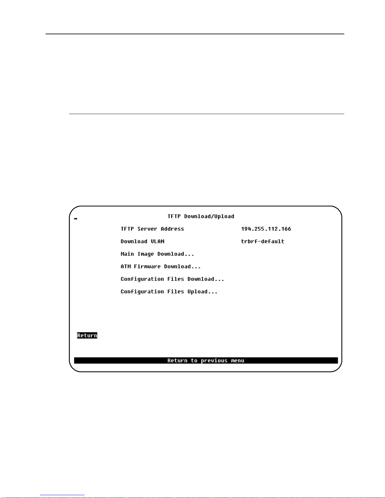
4. On this menu, set the IP address of the TFTP server. Also, set the download
VLAN (the BRF on which the TFTP server is located).
5. Select
ATM Firmware Download
screen is displayed.
6. Select
ATM Firmware Download Filename
software image to download.
7. Select
SmartStack SSIM-A2-01/SSIM-A8-01 Installation
Execute ATM Image Network Download
. The
ATM Firmware TFTP Download
and type the filename of the
to start the download.

10
The console will display the download activity while the sof twar e is transferred
over the network. When the software has been transferred, you will see the
following messages:
Network download complete. Now transferring to ATM
Module(s), please wait...
Download of ATM firmware complete - ATM module(s) being
reinitialized...
The software is then burned into the module FLASH memory. The software
remains in memory until replaced by a newer image. When the software installation
is complete, the module is started for normal operation, and the following message
is displayed:
Press <RETURN> to continue ...
Serial Download
1. From the main menu , sel ect
Download
Upload
→→→→
. The
Download
Upload
→→→→
menu is di splayed .
2. Select
3. Select
Serial Link Download
ATM Firmware Download
. The
Serial Link Download
.
screen is displa yed.
4. Using your terminal software, transfer the software image (ATMyzv.bi n) to the
module using the Xmodem protocol. The transfer will take some minutes,
depending on your terminal settings and speed.
The software is then burned into the module FLASH memory. The software
remains in memory until replaced by a newer image. When the software installation
is complete, the module is started for normal operation, and the following message
is displayed:
Press <RETURN> to continue ...
SmartStack SSIM-A2-01/SSIM-A8-01 Installation

Cabling
The cabling used depends on which version of the module you are installing.
SSIM-A2-01 ATM 155 Uplink UTP5
The SSM-A2-01 module uses standard copp er UTP5 cabling. Th e maximum cable
length is 100 m (328 feet).
1. Insert the modular jack from either end of an RJ45 UTP-5 cable into the
connector on the SSM-A2-01 front panel.
2. Connect the other end of the cable to an ATM switch in the network.
SSIM-A8-01 ATM 155 Uplink MMF
The SSIM-A8-01 module uses multimode 62.5/125 micron fiber cabling. The
maximum cable length is 2000 m (6560 feet).
1. Connect an SC-type optic fiber to the pair of SC-type connectors on the front
panel of the module. T o ensure pro per connection, it may be necessary to clean
the fiber connectors with a soft tissue dipped in alcohol.
11
➽
2. Connect the other end of the cable to an ATM switch in the network using the
following guidelines:
— Connect the module RX connector to the ATM switch TX port.
— Connect the module TX connector to the ATM switch RX port.
Note:
If there is no connection between the ATM switch and the SSIM-A8-01
module (the RXSYNC LED is of f), try swap ping the TX and RX connectors at one
end of the cable.
SmartStack SSIM-A2-01/SSIM-A8-01 Installation

12
LEDs
There are four LEDs on the front panel of the SSIM-Ax-01 module. The LEDs
show the module status and activity. Table 2 ex plains the status LEDs on the left of
the module front panel, and Table 3 explains the ATM interface LEDs o n the right
of the module front panel.
LED Position State Meaning
DIA G (green) Top On Diagnostics are in progress
Off No diagnostics are in process
ERR (yellow) Bottom On A module failure has
occurred
Off The m odule is wor king
correctly
Table 2. Status LEDs and their Meanings
LED Position State Meaning
RXSYNC (green) Top On The ATM interface is
receiving a signal
Off The ATM interface is not
attached to a live transmitter
SIGLOSS
(yellow)
Bottom On The ATM receive signal is
below an acceptable level
Off The AT M receive signal is
acceptable
Table 3. ATM Interface LEDs and their Meanings
Table 4 shows the LED status for the SSIM-Ax-01 modu le under normal operating
conditions.
SmartStack SSIM-A2-01/SSIM-A8-01 Installation

LED State
DIAG Off
ERR Off
RXSYNC On (green)
SIGLOSS Off
Table 4. Normal LED State
Testing the Module
1. Powe r on the base sw itch to st art diagnostic s. Diagnost ics are in pr ogress when
the STS16-20RM DIAG LED is on. After about a minute, the SSIM-Ax-01
DIAG LED will turn on, indicating that the expansion module diagnostic s are
in progress.
13
2. Verify that the base switch diagnostics have been completed successfully. You
can see that diagnostics have been completed successfully when the switch
DIAG LED turns off and the ERR LED stays off. Diagnostics can take up to
four minutes to complete.
3. Verify that the SSIM-Ax-01 ERR LED is of f. If th e ERR LED is of f, diagno stics
have been successfully completed, and the module is ready for configuration.
SmartStack SSIM-A2-01/SSIM-A8-01 Installation

14
Configuration
The SSIM-Ax-01 module can be configured using the RS-232-based console
configuration, Telnet, or the SNMP-based management application. (The SNMPbased management application is described in the online help).
Default Configuration
When the module is inserted for the first time, the module will be configured with
the default configuration, as described below:
One VAP in the default CRF.
•
LANE services using the LECS address con figured in the switch, subs equently
•
LECS at the LANE well-known address.
The ELAN name will be empty.
•
The maximum data frame size is 4544 (and the LAN type is Token Ring).
•
The signaling version is UNI 3.1.
•
The framing type is SONET.
•
You will need to reconfigure the module in the following cases:
If you want to change any of the defaults listed above.
•
If you want to change any of the more advanced parameters not listed above.
•
If you want to connect other CRFs than the default CRF to ATM.
•
❏
SmartStack SSIM-A2-01/SSIM-A8-01 Installation

3. Console Configuration
This chapter explains how to view and edit the configuration of the SSIM-Ax-01
ATM 155 Uplink Module using a VT100 console attached directly to the STS1620RM Token Ring Switch. The module config uration can also be modified from a
remote VT100 console via a telnet session. Connecting a network management
console is explained in the manual supplied with the switch.
The following topics are explained in this chapter:
Introduction
•
General Guidelines
•
ATM Configuration - Port Menu
•
— ATM Net work Configuration
— ATM Network Advanced Parameters
15
— ATM LEC Main Configuration Screen
Traffic Profiles
•
— Traffic Profile Mapping Configuration
— ATM LANE Parameters Configuration
— ATM LEC PVC Configuration
— ATM Traffic Profile Configuration
SmartStack SSIM-A2-01/SSIM-A8-01 Console Configuration

16
Introduction
In the console configuration, port numbers are used to refer to ports, with the
ordinary Token Ring ports being numbered 1 to 20. Using the console, the ATM
port will appear as port 21 when located in the left hand slot, and as port 25 when
located in the right hand slot. The ATM ports can be configured just like the
ordinary switch ports. They will appear as additional ports on any configuration
panel where ports are listed.
As a significant difference from the ordinary Token Ring ports, the ATM ports can
work as trunk ports, which means that they can carry traffic belonging to all
possible 63 VLANs over the same physical cable connection. That is, each ATM
port is divided into vi rtual ATM ports (VAPs). In the defaul t configuration an ATM
port will have one VAP in the default CRF. Assigning an ATM por t to se veral
CRFs will create new VAPs, but there can be only one VAP per BRF/VLAN.
After a VAP has been established as described above, you can configure the VAP
from the Port Configuration menu. Manually added VAPs will have the sam e
settings as the default VAP, except that the ELAN name will be set to the name of
the CRF. Note that a BRF (VLAN) can only be connected to any ATM ELAN once
on the same ATM module. This means that if more than one CRF is attached to
ATM by the same ATM module, the CRFs must connect to different ELANs.
General Guide l ine s
To work within the console menus, follow these guidelines:
To select a menu item, use the arrow keys to move the “highlight” over the
•
selection, then press
If you need to specify additional information for any item—for example,
•
selecting
you want to exit the prompt without changing the value, press
In most cases, new values are saved when you select
•
The term “More” means there is more infor mation than currently displayed on
•
that screen. Selecting
information. If the screen is a one-screen display, selecting
the screen.
The term “Port” refers to the number of a specific port on a switch.
•
“Index” refers to the numerical order of a list.
•
To return to the main menu from any screen within the menus, press
•
Note that any changes made to the s creen you were in are not s a v ed. To return
to the greeting screen, press
or No or supplying a value—a prompt appears on the screen. If
Yes
ENTER
More
.
and pressing
CTRL-B
from any screen.
ENTER
.
ESC
Return
displays the next screen of
.
More
will update
CTRL-P.
SmartStack SSIM-A2-01/SSIM-A8-01 Console Configuration

17
To refresh the console panel at any time, press
•
If you are administering switches in a stack, man y o f the conso le screens will
•
prompt for a bo x number. Enter the number of the box yo u w ant to adminis ter
to continue. The box that you are physically connected to is highlighted.
The console automatically returns to the greeting screen after five minutes of
•
inactivity. Five minutes is the default value. The time can be changed at the
Console Configuration
the
Configuration
For protection against inadvertent or unauthorized access to configuration
•
screens, you can set a password that us ers must enter at the greeting screen. If
no password is configured, just press
menu. The
menu, under the main menu.
Consol e Configur a t i o n
ENTER
CTRL-L
and the main menu is presented.
.
menu is within
Navigating within the Menus
Use the arrow keys (also referred to as cursor keys) to move the highlight over a
selection. If the select ion is a menu , press ing th e
of information; if the selection is a command, such as
key initiates that function.
ENTER
key displays a new s creen
Reset
, pressing the
ENTER
A heading with three “dots” after it means that when that heading is selected, a
submenu or screen is displayed.
Unless specified differently, all screens or menus are accessed in the same way.
SmartStack SSIM-A2-01/SSIM-A8-01 Console Configuration

18
ATM Configuration - Port Menu
To change the configuration of the SS IM-Ax -01 ATM 155 Uplink Module, select
Port Configuration
prompted. The following menu is displayed.
from the
Configuration
menu and type the p ort number when
The following items are available:
Enabled
Sets the administrative state of the port. Setting Enabled to Yes turn s the module
on. Setting Enabled to No turns the port off. Possible values are Y es and No.
Status
Shows the operative status of t he port. Up is disp layed when the port is running as
configured by the user. Down indicates that the port is not running—either because
Enabled was set to No or because an error has occurred. The information in this
field cannot be edited. Possible values are Up and Down.
Apply Changes
Configuration parameters for the module port can be changed from a console
session or remote telnet session. However, any changes to th e port configuration
will not take effect until the port is restarted. Selecting Apply Changes will restart
the port using the new configuration in for mation.
Note that traffic through the port will be disrupted while the port restarts.
SmartStack SSIM-A2-01/SSIM-A8-01 Console Configuration
 Loading...