

Cabletron Systems SmartSwitch Router 520, SmartSwitch Router 510 Installation And Configuration Manual

SmartSwitch Router
510 and 520
Installation and Configuration Guide
9032869


Notice
Only qualified personnel should perform installation procedures.
NOTICE
Cabletron Systems reserves the right to make changes in specifications and other information
contained in this document without prior notice. The reader should in all cases consult Cabletron
Systems to determine whether any such changes have been made.
The hardware, firmware, or software described in this manual is subject to change without notice.
IN NO EVENT SHALL CABLETRON SYSTEMS BE LIABLE FOR ANY INCIDENTAL,
INDIRECT, SPECIAL, OR CONSEQUENTIAL DAMAGES WHATSOEVER (INCLUDING
BUT NOT LIMITED TO LOST PROFITS) ARISING OUT OF OR RELATED TO THIS
MANUAL OR THE INFORMATION CO NTAINED IN IT, EVEN IF CABLETRON SYSTEMS
HAS BEEN ADVISED OF, KNOWN, OR SHOULD HAVE KNOWN, THE POSSIBILITY OF
SUCH DAMAGES.
1999 by Cabletron Systems, Inc.
All Rights Reserved. Printed in the United States of America.
Cabletron Systems, Inc.
35 Industrial Way
Rochester, NH 03867-0505
Order Number: 9032869 February 1999
Cabletron Systems and SPECTRUM are registered trademarks, and SmartSwitch is a trademark
of Cabletron Systems, Inc.
IPX is a registered trademark of Novell, Inc .
DEC, DIGITAL, and the DIGITAL logo are trademarks of Compaq Compu ter Corporation.
All other trademarks and registered trad emarks are the property of their respective holders.
i

Notice
FCC NOTICE
This device complies with Part 15 of the FCC rules. Operatio n is subject to the following two
conditions: (1) this device may not cause harmful interference, and (2) this device must accept any
interference received, including interference that may cause undesired operation.
NOTE: This equipment has been tested and found to comply with the limits for a Class A digital
device, pursuant to Part 15 of the FCC rules. These limits are designed to provide reasonable
protection against harmful interference when the equipment is operated in a commercial
environment. This equipment uses, generates, and can radiate radio frequency energy and if not
installed in accordance with the operator’s manual, may cause harmful interference to radio
communications. Operation of this equipment in a residential area is likely to cause interference in
which case the user will be required to correct the interference at his own expense.
WARNING: Changes or modifications made to this device which are not expressly approved by
the party responsible for compliance could void the user’s authority to operate the equipment.
VCCI NOTICE
This is a Class A product based on the standard of the Voluntary Control Council for Interference
by Information Technology Equipment (VCCI). If this equipment is used in a domestic
environment, radio disturbance may arise. When such trouble occurs, the user may be required to
take corrective actions.
INDUSTRY CANADA NOTICE
This digital apparatus does not exceed the Class A limits for radio noise emissions from digital
apparatus set out in the Radio Interference Regulations of the Canadian Department of
Communications.
Le présent appareil numérique n'émet pas de bruits radioélectriques dépassant les limites
applicables aux appareils numériques de la class A prescrites dans le Règlement sur le brouillage
radioélectrique édicté par le ministère des Communications du Canada.
ii

Notice
TAIWANESE NOTICE — CLASS A COMPUTING DEVICE
CE NOTICE — CLASS A COMPUTING DEVICE
Warning!
This is a Class A product. In a domestic environment, this product may cause radio interference, in
which case the user may be requir ed to take adequate measures.
Achtung!
Dieses ist ein Gerät der Funkstörgrenzwertklasse A. In Wohnbereichen können bei Betrieb dieses Geräte s
Rundfunkstörungen auftreten, in welchen Fällen der Benutzer für entsprechende Gegenma
verantwortlich ist.
Avertissement!
Cet appareil est un appareil de Classe A. Dans un environnement résidentiel cet appareil peut provoquer des
brouillages radioélectriques. Dans ce cas, il peut être demandé à l'utilisateur de prendre les mesures
appropriées.
ßnahmen
CABLETRON SYSTEMS, INC. PROGRAM LICENSE AGREEMENT
IMPORTANT: Before utilizing this product, carefully read thi s Lic ense Agreement.
This document is an a greement between you, the end user, and Cabletron Systems, Inc . (“ Cabletron”) that set s forth your
rights and obliga tions with respect to the Cabletron software program (the “Program”) contai ned in this package. The
Program may be contained in firmware, chips or other media. BY UTILIZING THE ENCLOSED PRODUCT, YOU ARE
AGREEING TO BECOME BOUND BY THE TERMS OF THIS AGREEMENT, WHICH INCLUDES THE LICENSE
AND THE LIMITATION OF WARRANTY AND DISCLAIMER OF LIABILITY. IF YOU DO NOT AGREE TO THE
TERMS OF THIS AGREEMENT, PROMPTLY RETURN THE UNUSED PRODUCT TO THE PLACE OF PURCHASE
FOR A FULL REFUND.
CABLETRON SOFTWARE PROGRAM LICENSE
1. LICENSE. You have the right to use only the one (1) copy of the Program provided in this package subject to the terms
and conditions of t hi s L ic ense Agreement.
You may not copy, reproduce or transmit any part of the Program except as permitted by the Copyright Act of the
United States or as auth orized in writing by Ca bletron.
2. OTHER RESTRICTIONS
3. APPLICABLE LAW
federal courts of New Hampshire. You accept the per s ona l j uri sd ic tion and venue of the New Ham pshire courts.
. You may not reverse engineer, dec om pi le , or disassemble the Program.
. This License Agreement shall be interpreted and governe d under the laws and in the state and
iii

Notice
EXCLUSION OF WARRANTY AND DISCLAIMER OF LIABILITY
1. EXCLUSION OF WARRANTY. Except as may be specifically provided by Cabletron in writing, Cabletron makes
no warranty, expresse d or im plied, concernin g the Program (includ ing its do cumentation an d me dia).
CABLETRON DISCLAIMS ALL WARRANTIES, OTHER THAN THOSE SUPPLIED TO YOU BY
CABLETRON IN WRITING, EITHER EXPRESSED OR IMPLIED, INCLUDING BUT NOT LIMITED TO
IMPLIED WARRANTIES OF MERCHANTABILITY AND FITNESS FOR A PARTICULAR PURPOSE, WITH
RESPECT TO THE PROGRAM, THE ACCOMPANYING WRITTEN MATERIALS, AND ANY
ACCOMPANYING HARDWARE.
2. NO LIABILITY FOR CONSEQUENTIAL DAMAGES
SUPPLIERS BE LIABLE FOR ANY DAMAGES WHATSOEVER (INCLUDING, WITHOUT LIMITATION,
DAMAGES FOR LOSS OF BUSINESS, PROFITS, BUSINESS INTERRUPTION, LOSS OF BUSINESS
INFORMATION, SPECIAL, INCIDENTAL, CONSEQUENTIAL, OR RELIANCE DAMAGES, OR OTHER LOSS)
ARISING OUT OF THE USE OR INABILITY TO USE THIS CABLETRON PRODUCT, EVEN IF CABLETRON
HAS BEEN ADVISED OF THE POSSIBILITY OF SUCH DAMAGES. BECAUSE SOME STATES DO NOT
ALLOW THE EXCLUSION OR LIMITATION OF LIABILITY FOR CONSEQUENTIAL OR INCIDENTAL
DAMAGES, OR ON THE DURATION OR LIMITATION OF IMPLIED WARRANTIES, IN SOME INSTANCES
THE ABOVE LIMITATIONS AND EXCLUSIONS MAY NOT APPLY TO YOU.
. IN NO EVENT SHALL CABLETRON OR ITS
UNITED STATES GOVERNMENT RESTRICTED RIGHTS
The enclosed product (a) was developed sole ly at private expense ; (b) c ontains “restricted computer software” submitted
with restricted rig ht s in ac cordance with Section 52227-19 (a) through (d) of the Commerc ia l Computer Software Restricted Rights Cla use and its successors, and (c) in al l respects is proprieta ry data belonging to Cabletron and/or its
suppliers.
For Department of Defense uni ts, the product is licensed with “Restricted Rights” as defin ed in the DoD Supplement to the
Federal Acquisiti on Re gulations, Section 52.227-7013 (c) (1) (ii ) and its successors, and use, dup lication, disclosur e by t he
Government is subject to restrictions as set fort h in subparagraph (c) (1) (ii) of the Rights in Technical Data and Com put er
Software clause at 252.227 -7013. Cabletron Systems, Inc. , 35 Ind ustrial Way, Rochester, New Hampshire 03867-0505.
iv

Declaration of Conformity
Addendum
Application of Council Directive(s): 89/336/EEC
73/23/EEC
Manufacturer’s Name: Cabletron Systems, Inc.
Manufacturer’s Address: 35 Industrial Way
PO Box 5005
Rochester, NH 03867
European Representative Name: Mr. J. Solari
European Representative Address: Cabletron Systems Limited
Nexus House, Newbury Business Park
London Road, Newbury
Berkshire RG13 2PZ, England
Conformance to Directive(s)/Product Standards: EC Directive 89/336/EEC
EC Directive 73/23/EEC
EN 55022
EN 50082-1
EN 60950
Equipment Type/Environment: Networking Equipment, for use in a
Commercial or Light
Industrial Environment.
Notice
We the undersigned, hereby declare, under our sole responsibility, that the equipment
packaged with this notice conforms to the above directives.
Manufacturer Legal Representative in Europe
Mr. Ronald Fotino Mr. J. Solari
____________________________________________________ ____________________________________
Full Name Full Name
Principal Compliance Engineer Managing Director - E.M.E.A.
____________________________________________________ ____________________________________
Title Title
Rochester, NH, USA Newbury, Berkshire, England
____________________________________________________ ____________________________________
Location Location
v


Preface
Overview.......................................................................................................xi
Using This Guide..........................................................................................xi
Intended Audience .......................................................................................xi
Structure of This Guide................................................................................xii
Related Documentation............................................................................. xiii
Document Convention .................................................................................xv
Glossary ......................................................................................................xvi
Getting Help...............................................................................................xvii
Chapter 1 Product Introduction
Overview....................................................................................................1-1
Chapter Contents........................................................................................ 1-1
What Are the SmartSwitch Router 510 and SmartSwitch Router 520? .... 1-2
SSR-510 Router................ ..... ...... ....................................................... 1-2
SSR-520 Router................ ..... ...... ....................................................... 1-2
Features................... ..... ...... .................................. .................................. .... 1-3
Performance and Memory .................................................................. 1-3
Configuration and Management......................................................... 1-3
EasyStart............................................................................................. 1-4
Front and Back Panel Components............................................................ 1-5
Front Panel Components..................................................................... 1-5
Back Panel Components..................................................................... 1-8
Contents
Chapter 2 Installing and Cabling
Overview....................................................................................................2-1
Chapter Contents........................................................................................ 2-1
Installing the Router in the Rack Mounting Shelf..................................... 2-2
Assembling the Rack Mount Shelf..................................................... 2-3
Attaching Adhesive Strips.................................................................. 2-4
Cabling the Routers........................................ ...... ...... ................................ 2-6
Cabling the SSR-510 .............................. ...... ...................................... 2-6
Cabling the SSR-520 .............................. ...... ...................................... 2-8
vii

Removing the Cables.......................................................................................2-10
Removing the SSR-510 Cables.................................................................2-10
Removing the SSR-520 Cables.................................................................2-11
Chapter 3 Connecting the Console Port Cable
Overview............................................................................................................3-1
Chapter Contents................................................................................................3-1
Signaling Standards............................................................................................3-2
Console Port Device Cabling.............................................................................3-2
Connecting the Console Port..............................................................................3-3
Chapter 4 Configuring the Router
Overview............................................................................................................4-1
Chapter Contents................................................................................................4-1
Using the Router Configurator to Configure the Router....................................4-2
Console Screens..........................................................................................4-4
Using the CLI to Manually Configure the Router .............................................4-6
Preconfigured Router Screen.................................................... ..................4-9
Using Menus to Setup the Router....................................................................4-10
[1] Restart with Factory Defaults..............................................................4-11
[2] Restart with Current Settings..............................................................4-12
[3] Show Current Settings.........................................................................4-13
[4] IP Configuration..................................................................................4-14
[1] Set SNMP Read/Write Community.............................................4-15
[2] Set In-Band Interface IP Address ................................................4-16
[3] Set Default Gateway ....................................................................4-17
Go to Local Console.................................................................................4-18
[5] Go To Local Console...........................................................................4-19
Contents
Chapter 5 Supporting ISDN for the SSR-510
Overview............................................................................................................5-1
Chapter Contents................................................................................................5-1
Ordering Your ISDN Line..................................................................................5-2
Obtaining a Network Termination Device ........................................................5-3
viii

Contents
Appendix A Problem Solving
Overview....................................................................................................A-1
Appendix Contents.....................................................................................A-1
Normal Powerup ........................................................................................A-2
Self-Test Progress States............................................................................A-3
LED Descriptions.................................................................. .....................A-5
Problem Solving Using the LEDs..............................................................A-7
Appendix B Connectors, Adapters and Cable Connections
Overview....................................................................................................B-1
Appendix Contents.....................................................................................B-1
Connector Assignments............................. ..... ............................................B-2
10BaseT Port (8-pin MJ) Connector..........................................................B-4
Adapters .....................................................................................................B-5
H8571-J Adapter................................................. ..... ...........................B-5
H8575-A Adapter................................................................................B-5
Cable Connections...................................................................................... B-6
Appendix C Product Specifications
Overview....................................................................................................C-1
Appendix Contents.....................................................................................C-1
Product Specifications................................................................................C-2
Acoustical Specifications...........................................................................C-3
Connectors..................................................................................................C-4
Parts List.....................................................................................................C-5
Appendix D Installation Information – United Kingdom
Overview....................................................................................................D-1
Appendix Contents.....................................................................................D-1
Service Categories......................................................................................D-2
Power Rating, Router Isolation and Safety Status .....................................D-3
Host Power Rating..............................................................................D-3
Router Isolation...................................................................................D-3
Safety Status........................................................................................D-3
ix

Contents
Cable Approval..........................................................................................D-4
Supported Cables................................................................................D-4
Equipment Between the Approved Router and a Digital Circuit (PTT)....D-5
x

Preface
Preface
Preface
Overview
This manual describes how to install the SmartSwitch Router 510 and SmartSwitch
Router 520 (also referred to in this manual as SSR-510 and SSR-520). It also provides
problem solving information, connector pin assignments, and other general information.
Using This Guide
Read through this guide completely to understand the router features, capabilities, and
Local Management functions. A general working knowledge of Ethernet and IEEE 802.3
type data communications networks and their physical layer components is helpful when
using these devices.
Intended Audience
This manual is intended for the hardware installer. The installer is responsible for ensuring
that the h ardware is installed and teste d. It shows how to inst all when th e site is ve rified
and the cables and devices are in place. This guide shows how to verify the site, install
cables and devices and troubleshoot problems. The person installing software can then
verify the system inst allation.
xi

Preface
Structure of This Guide
This guide is organized as follows:
Chapter/
Appendix
Title Description
Chapter 1 Product Introduction
Chapter 2 Installing and Cabling
Chapter 3 Connecting the
Console Port Cable
Chapter 4 Configuring the
Router
Chapter 5 Supporting ISDN for
the SSR-510
Appendix A
Appendix B
Problem Solving
Connectors, Adapters
and Cable
Connections
Describes the SS R-510 and SS R-520 rout ers and thei r
features.
Provides instructions for installing the router in a Rack
Mounting Shelf and cabling the routers.
Provides instructions for connecting the rou ter to th e
console port.
Describes how to configure the routers using menus.
Describes ordering an ISDN line and obtaining a
network terminator device.
Provides installation-specific problem solving
information using the LEDs.
Describes connectors and pin assignments, adapters,
and cable connections.
Appendix C
Product
Specifications
Appendix D
Installati on
Informati on - United
Kingdom
xii
Provides product specifications and a parts list.
Contains installation information requ ired for the
United Kingdom.

Preface
Related Documentation
The following documents may help the user to configure and manage the SmartSwitch
Router SSR-510 and SSR-520:
Part Number Title Description
SmartSwitch Router 500 Series
Bridging Configuration Guide
SmartSwitch Router 500 Series
Event Logging System
Messages Guide
SmartSwitch Router 500 Series
Network Interface Operations
Guide
SmartSwitch Router 500 Series
Routing Protocols Reference
Guide
Describes bridging methods,
operational features of bridging,
configuration methods, basic
configurations, and monitoring the
bridging functional ity.
Describes messages logged by the
Event Logging System (ELS).
Describes the configuration and
monitoring th e supported network
interfaces.
Provides detailed reference
information about protocols and
interfaces supported by the router.
SmartSwitch Router 500 Series
Routing Protocols Users Guide
SmartSwitch Router 500 Series
Router Configurator User’s
Guide
SmartSwitch Router 500 Series
System Software Guide
Explains how to configure and monitor
the routing protocols supported by the
router.
Explains how to install the Router
Configurator software, and use it to
create and load configurations into the
6PDUW6ZLWFK5RXWHU6HULHV
routers.
Provides information about installing,
configuring, and operating the router
system software.
xiii

Preface
Part Number Title Description
SmartSwitch Router 500 Series
System Quick Reference Guide
SmartSwitch Router 500 Series
Systems Network Architecture
Guide
SmartSwitch Router 500 Series
DTF (Digital Trace Facility)
User Guide
Provides quick r eference informati on
about configuring the
5RXWHU6HULHV
Describes how to use SDLC Relay to
route SNA traffic across a WAN.
6PDUW6ZLWFK
system software.
How to install and use the trace
facility which enables you to trace
packets within the protocol layers
of the 6PDUW6ZLWFK5RXWHU.
The manuals referenced above can be obtained on the World Wide Web (refer to the
section titled Getting Help).
xiv

Preface
Document Conventions
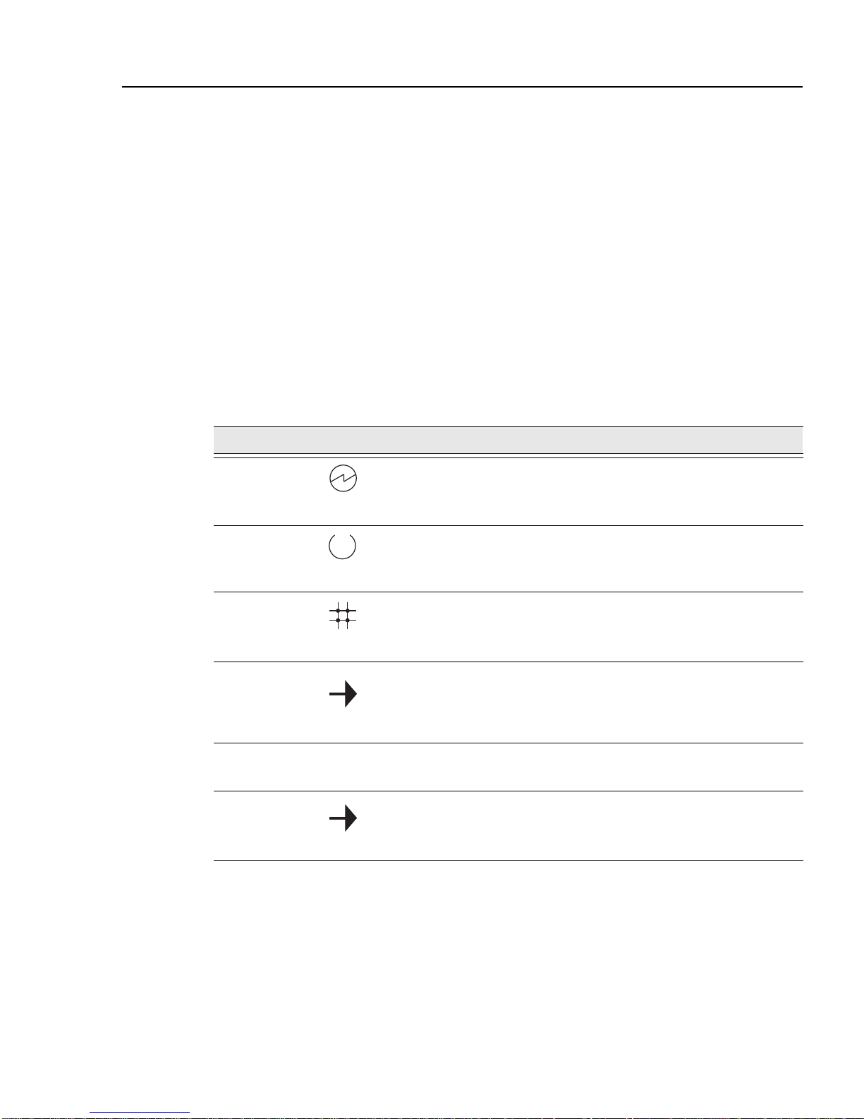
Throughout this guide, the following symbols are used to call attention to important
information.
Note symbol. Calls the reader’s attention to any item of information that may be of
special importance.
Caution symbol. Contains information essential to avoid damage to the equipment.
!
Electrical Hazard W arning symbol. Warns against an action that could result in the
presence of an electrical hazard.
xv

Preface
Glossary
This book uses the following terms:
Term Definition
Basic Rate A specific ISDN offering providing users with two
64Kb/s data channels (e.g. “B” channels) and one
16Kb/s signalling channel (e.g. “D” channel).
CLI Command Line Interface
Dedicated
Ethernet cable
DRS Distributed Routing Software
Ethernet A term used for product compatibility with ISO 8802-3/
SNMP Simple Network Management Protocol, an industry
SSR SmartSwitch Router
WAN Wide Area Network. A generic term used to identify
IEEE 10Base2 coaxial cable that carries Ethernet signals.
ANSI/IEEE 802.3 standards and the Ethernet standards
for CSMA/CD local area networks (LANs).
standard protocol for network management.
serial links which traverse large geographic areas.
xvi

Getting Help
For additional support related to this device or document, contact the
Cabletron Systems using one of the following methods:
World Wide Web http://www.cabletro n.com/
Phone (603) 332-9400
Internet mail support@cabletron.com
FTP ftp://ftp.cabletron.com/
Login
Password
To send comment s or sug ge stions con cernin g this do cumen t, cont act th e Cabl etron
Systems Technical Writing Department via the following
email address: TechWriting@cabletron.com
Make sure to include the document Part Number in the email message.
Preface
anonymous
your email address
Before calling Cabletron Systems, have the following information ready:
• Your Cabletron Systems service contract number
• A description of the failure
• A description of any action(s) already taken to resolve the problem (e.g.,
changing mode switches, rebooting the unit, etc.)
• The serial and revision numbers of all involved Cabletron Systems
products in the network
• A description of your network environment (layout, cable type, etc.)
• Network load and frame size at the time of trouble (if known)
• The device history (i.e., have you returned the device before, is this a
recurring problem, etc.)
• Any previous Return Material Authorization (RMA) numbers
xvii


Product Introduction
Overview
This chapter provides a description of the SmartSwitch Router 510 and
SmartSwitch Router 520 (also referred to in this manual as SSR-510 and
SSR-520) and their features.
Chapter Contents
Chapter 1
Topic Page
What Are the SmartSwitch Router 510 and SmartSwitch Router
520?
SSR-510 Router 1-2
SSR-520 Router 1-2
Features 1-3
Performance and Memory 1-3
Configuration and Management 1-3
EasyStart 1-4
Front and Back Panel Components 1-5
Front Panel Componen ts 1-5
Back Panel Components 1-8
1-2
1-1

Product Introduction
What Are the SmartSwitch Router 510 and
SmartSwitch Router 520?
The SmartSwitch Router SSR-510 and SmartSwitch Router SSR-520 (also
referred to in this manual as the SSR-510 and SSR-520 routers) provide
multiprotocol rou ting for linking Ethernet LANs to corporate Wide Area
Networks (WAN).
The routers off er fle xi ble sof twa re s uppo rt tha t ca n be tai lo re d to t he n eeds of
specific remote environments.
The SSR-510 and SSR-520 router s are available wi th Multiprotocol Sof tware.
Protocol support, for your package, is described in the Cabletron Distributed
Routing Software Release Notes.
The SSR-510 and SSR-520 standards-compliant technology ensures
interoperability in multivendor networks.
SSR-510 Router
The SSR-510 router has the following port connections:
• One Ethernet interface, in either dedicated Ethernet (10Base2) or twisted
pair (10BaseT)
• One synchronous serial WAN port capable of T1/EI data rates
• One ISDN basic rate interface (BRI) S/T-interfa ce
SSR-520 Router
The SSR-520 router has the following port connections:
• One Ethernet interface, in either dedicated Ethernet (10Base2) or twisted
pair (10BaseT)
• Two synchronous WAN ports capable of T1/EI rates
1-2

Features
The SSR-510 and SSR-520 routers include the following features.
Performance and Memory
The SSR-510 and SSR-520 routers conta in the followin g performance and
memory features:
• Industry-standard processors operating at 22.5 MHz clock rates, and
utilizes 32-bit address and data buses for maximum bus bandwidth.
• 4 MB of system flash memory.
• 4 MB of system memory using PC compatible memory DSIMMS.
• Memory accesses are parity protected on a byte wide basis.
Product Introduction
Configuration and Management
The following configuration and management options are available:
• Support for the following configuration options:
–– EasyStart configuration loader
–– Graphical User Interface (GUI) using the clearVISN Router
Configurator tool
–– Command Line Interface (CLI) using the console port
–– CLI using Telnet
• Upgradeable device firmware (in nonvolatile Flash memory) using
Trivial File Transfer Protocol (TFTP).
• Simple Network Management Protocol (SNMP) for monitoring.
1-3

Product Introduction
EasyStart
EasyStart is a featur e that allo ws you to downlin e load configur ation files
that are stored on a server via BOOTP/TFTP.
Using EasyStart and t he clearVISN Router Configurator eliminates the
need for configuring the router using the Command Line Interface (CLI).
When the router is booted, it autoconfigures all interfaces and sends out
requests to load its configuration file. Once the file is received, the router
automatically r estart s so that the confi guratio n paramet ers spec ified i n the
file take effect.
Refer to the SmartSwitch Router 500 Series System Software Guide for
information about using the EasyStart feature.
1-4
Front and Back Panel Components
The following sections describe the front and back panel components for the
SSR-510 or SSR-520 routers.
Front Panel Components
Table 1-1 describes the front panel components, including LEDs, that are
illustrated in Figure 1-1.
For problem-solving information using the LEDs, refer to Appendix A.
Table 1-1. Front Panel LEDs and Connectors
Item Icon Name Description
1 Power LED Lights when the router has power.
Product Introduction
2 Module OK LED Lights when the router passes self-
test.
3 Network OK LED Indicates network connection or port
state.
4 Network Activity
LED
5 Port 1 Serial Line
OK LED
6 Port 1 Serial Line
Activity Indicator
Indicates network traffic connection.
Blinks faster as traffic becomes
heavier.
Indicates self-test pass or failure.
Indicates operation mode on port 1.
Continued on next page ...
1-5

Product Introduction
Item Icon Name Des cription
Table 1-1. Front Panel LEDs and Connectors
7 Port 2 Serial Line
OK LED (for
SSR-520)
ISDN Port OK
(for SSR-510)
8
Port 2 Serial Line
Activity Indicator
(for SSR-520)
ISDN Activity
Indicator (for
SSR-510)
9 Twisted Pair
(10BaseT)
Connector
10 Synchronous
Serial Port
Connectors
(labeled 1 and 2
for SSR-520)
Indicates self-test pass or failure.
Indicates self-test pass or failure.
Indicates operation mode on port 2.
Indicates operation mode on ISDN
port.
Connects the router to a 10BaseT
network.
These ports support the EIA53 0A,
RS232/V.28, RS422/V.11, V.35, X.21
Leased Lines (LL), RS423/V.10
11 Console Port
Connection
Connects a console terminal that is
used to manage the console. Uses an
8-pin MJ connector.
12 Dump Button Forces a dump of router memory.
Refer to the Distributed Router
Software System Software Guide for
more information.
13 Ethernet Network
Connector (BNC)
Connects the router to the dedicated
Ethernet segment. Not used when the
router is connected through the
twisted pair (10BaseT) connector.
14 Ethernet Label Lists the Ethernet address of the
module.
15 ISDN Connection
(labeled 2 for
Connects the module to an ISDN
segment. Uses an 8-pin MJ connector.
SSR-510)
1-6
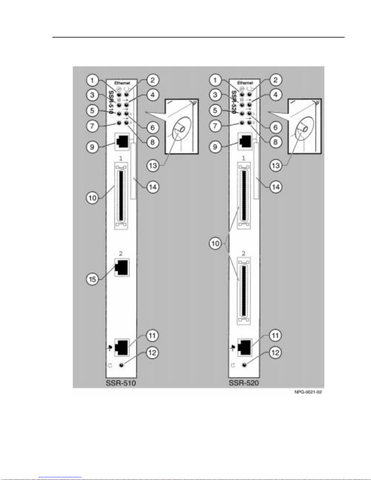
Figure 1-1. Front Panel LEDs and Connectors
Product Introduction
1-7

Product Introduction
Back Panel Components
Table 1-2 describes the back panel components that are illustrated in
Figure 1-2.
Table 1-2. Back Panel Feature Components
Item Name Description
1 Power Connector Receives dc current from the power supply.
1-8
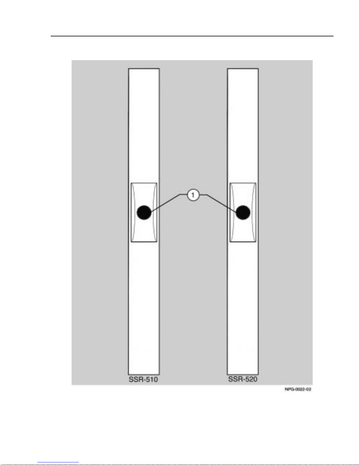
Figure 1-2. Back Panel Layout
Product Introduction
1-9

 Loading...