

Cabletron Systems SmartStack STS-8SU, STS-SM, SmartStack STS-SM Installation And User Manual
Page 1

SmartStack
STS-8SU External Stacker Unit
&
STS-SM Switch Matrix
Installation
and
User Guide
Page 2

Notice
Cabletron Systems reserves the right to make changes in specifications and other
information contained in this document without prior notice. The reader should in all
cases consult Cabletron Systems to d etermine whether any such chan ges have b een made.
The hardware, firmware, or software described in this manual is subject to change
without notice.
IN NO EVENT SHALL CABLETRON SYSTEMS BE LIABLE FOR ANY
INCIDENTAL, INDIRECT, SPECIAL, OR CONSEQUENTIAL DAMAGES
WHATSOEVER (INCLUDING BUT NOT LIMITED TO LOST PROFITS) ARISING
OUT OF OR RELATED TO THIS MANUAL OR THE INFORMATION CONTAINED
IN IT, EVEN IF CABLETRON SYSTEMS HAS BEEN ADVISED OF, KNOWN, OR
SHOULD HAVE KNOWN, THE POSSIBILITY OF SUCH DAMAGES.
i
© October 1999 by:
Cabletron Systems, Inc.
35 Industrial Way
Rochester, NH 03867
All Rights Reserved.
Order Number: 9032968-01
(OC-7060 v. 1.1, 710001814)
SmartStack
CompuServe
i960 microprocessor
Ethernet
is a trademark of Cabletron Systems, Inc.
is a registered trademark of CompuServe, Inc.
is a registered trademark of Intel Corp.
is a trademark of Xerox Corporation.
Notice
Page 3
ii
FCC Notice
This device complies with Part 15 of the FCC rules. Operation is subject to the following
two conditions: (1) this device may not cause harmful interference, and (2) this device
must accept any interference received, including interference that may cause undesired
operation.
NOTE:
digital device, pursuant to Part 15 of the FCC rules. These limits are designed to provide
reasonable protection against harmful interference when the equipment is operated in a
commercial environment. This equipment uses, generates, and can radiate radio
frequency energy and if not installed in accordance with the operator’s manual, may
cause harmful interference to radio communications. Operation of this equipment in a
residential area is likely to cause interference in which case the user will be required to
correct the interference at his own expense.
WARNING:
approved by the party responsible for compliance could void the user’s authority to
operate the equipment.
This equipment has been tested and found to comply with the limits for a Class A
Changes or modifications made to this device which are not expressly
VCCI Notice
This is a Class A product based on the standard of the Voluntary Control Council f or
Interference by Information Technology Equipment (VCC I). If this eq ui pmen t is used in
a domestic environment, radio dis turban ce may arise. When s uch troub le occur s, the us er
may be required to take corrective actions.
Industry Canada Notice
This digital apparatus does not exceed the Class A limits for radio noise emissions from
digital apparatus set out in the Radio Interference Regulations of the Canadian
Department of Communications.
Le présent appareil numérique n'émet pas de bruits radioélectriques dépassant les limites
applicables aux appareils numériques de la class A prescrites dans le Règlement sur le
brouillage radioélectrique édicté par le ministère des Communications du Canada.
Notice
Page 4

Declarati on of Co nformity
Addendum
iii
Application of Council Directive(s):
Manufacturer’s Name:
Manufacturer’s Address:
European Representati v e Name :
European Representative Address:
Conformance to Directive(s)/Product Standards:
Equipment Type/Environment:
89/336/EEC
73/23/EEC
Cabletron Systems, Inc.
35 Industrial Way
PO Box 5005
Rochester, NH 03867
Mr. J. Solari
Cabletron Systems Limited
Nexus House,
Newbury Business Park
London Road, Newbury
Berkshire RG13 2PZ, England
EC Directive 89/336/EEC
EC Directive 73/23/EEC
EN 55022
EN 50082-1
EN 60950
Networking Equipment, for use
in a Commercial or Light
Industrial Environment.
We the undersigned, hereby declare, under our sole responsibility, that the equipment
packaged with this notice conforms to the above directives.
Manufacturer Legal Representative in Europe
Mr . Ronald Fotino
Full Name Full Name
Principal Compliance Engineer
Title Title
Rochester, NH, USA
Location Location
Mr. J. Solari
Managing Director - E.M.E.A.
Newbu ry , Berkshire, England
Notice
Page 5

iv
Notice
Page 6

Table of Contents
1. Overview and Specifications 1
Overview . . . . . . . . . . . . . . . . . . . . . . . . . . . . . . 1
SmartStack STS-SM Switch Matrix . . . . . . . . . . . . . . 2
Features and Specifications . . . . . . . . . . . . . . . . . . . . 3
Features . . . . . . . . . . . . . . . . . . . . . . . . . . . . 3
Specifications. . . . . . . . . . . . . . . . . . . . . . . . . . 4
2. Switch Stacker Theory of Operation 5
Switch Stacker: A Unique Concept. . . . . . . . . . . . . . . . . 5
Stack Features . . . . . . . . . . . . . . . . . . . . . . . . . . . 6
Creating a Switch Stack . . . . . . . . . . . . . . . . . . . . . . 7
SmartStack STS-8SU Stacker Unit Description . . . . . . . . 7
Forming a Multi-Unit Switch Stack . . . . . . . . . . . . . . . 7
Inter-box Parameters. . . . . . . . . . . . . . . . . . . . . . . . 9
Provider of Inter-box Parameters. . . . . . . . . . . . . . . 11
v
3. Preparing for Installation 13
Safety Recommendations . . . . . . . . . . . . . . . . . . . . 13
Safety with Electricity. . . . . . . . . . . . . . . . . . . . . 13
Preventing Electrostatic Discharge Damage. . . . . . . . . 14
Site Requirements . . . . . . . . . . . . . . . . . . . . . . . . 15
Environment . . . . . . . . . . . . . . . . . . . . . . . . . 15
Chassis Accessibility . . . . . . . . . . . . . . . . . . . . . 15
Cooling and Airflow. . . . . . . . . . . . . . . . . . . . . . 15
Power. . . . . . . . . . . . . . . . . . . . . . . . . . . . . 16
Package Contents . . . . . . . . . . . . . . . . . . . . . . . . 17
4. Installation 19
Mounting the Chassis . . . . . . . . . . . . . . . . . . . . . . 19
Rack or Cabinet Mounting . . . . . . . . . . . . . . . . . . 19
Table-Mounting. . . . . . . . . . . . . . . . . . . . . . . . 21
Cabling a Stack. . . . . . . . . . . . . . . . . . . . . . . . . . 22
Connecting Switches to the Switch Stacker . . . . . . . . . 22
Checking the Installation . . . . . . . . . . . . . . . . . . . . . 25
Applying Power. . . . . . . . . . . . . . . . . . . . . . . . 25
STS-8SU External Stacker Unit Control Panels . . . . . . . . . 27
Front Panel. . . . . . . . . . . . . . . . . . . . . . . . . . 27
Back Panel . . . . . . . . . . . . . . . . . . . . . . . . . . 28
STS-8SU External Stacker Unit Chassis Description . . . . 28
STS-SM Switch Matrix . . . . . . . . . . . . . . . . . . . . . . 29
SmartStack STS-8SU & STS-SM Installation and User Guide
Page 7

vi
SmartStack STS-SM Switch Matrix Unit Installation. . . . . . 29
STS-SM Switch Matrix Unit Operation. . . . . . . . . . . . . . . 30
Automatic Switch-Over from a SmartStack STS16-20RM. . . 31
Manual Switch-Overs . . . . . . . . . . . . . . . . . . . . . 31
Switch-Over Impact on Traffic . . . . . . . . . . . . . . . . . 31
Installing a SmartStack STS-LM Link Module . . . . . . . . . . . 33
Installing the STS-LM Link Module . . . . . . . . . . . . . . 33
SmartStack STS-LM Link Module Module Cables. . . . . . . 34
5. Accessing Switch Management 35
Overview. . . . . . . . . . . . . . . . . . . . . . . . . . . . . . 35
Connecting the Console . . . . . . . . . . . . . . . . . . . . . .36
Communication Problems . . . . . . . . . . . . . . . . . . . . .38
Diagnostic Screen . . . . . . . . . . . . . . . . . . . . . . . . . 39
6. Switch Configuration 41
General Guidelines . . . . . . . . . . . . . . . . . . . . . . . .41
Navigating within the Menus. . . . . . . . . . . . . . . . . . 42
Main Menu Screen. . . . . . . . . . . . . . . . . . . . . . . . .43
Configuration... . . . . . . . . . . . . . . . . . . . . . . . . 43
Statistics... . . . . . . . . . . . . . . . . . . . . . . . . . . . 43
Download/Upload... . . . . . . . . . . . . . . . . . . . . . . 43
Reset... . . . . . . . . . . . . . . . . . . . . . . . . . . . . 43
Exit Console . . . . . . . . . . . . . . . . . . . . . . . . . . 43
Configuration Menu . . . . . . . . . . . . . . . . . . . . . . . . 44
Switch Configuration Screen. . . . . . . . . . . . . . . . . . . . 45
Stack Configuration Screen . . . . . . . . . . . . . . . . . . 48
7. Getting in Touch With Technical Support 51
Problem Report Form . . . . . . . . . . . . . . . . . . . . . . . 52
Appendix A. Abbreviations 55
SmartStack STS-8SU & STS-SM Installation and User Guide
Page 8

List of Figures
Figure 1. Front View of the SmartStack STS-8SU Stacker . . . . . . 1
Figure 2. Exposing the Rack Mounting Brackets . . . . . . . . . . . 20
Figure 3. Mounting the Switch Stacker in a Rack or Cabinet . . . . . 21
Figure 4. Connecting the Stack Port Cable to Port 1
on the Switch Stacker . . . . . . . . . . . . . . . . . . . . 22
Figure 5. Connecting the Stack Port Cable to the Stack Link
Module on a Switch . . . . . . . . . . . . . . . . . . . . . 23
Figure 6. Back View of the Switch Stacker Cabled to Eight Switches . 24
Figure 7. The AC Connector for the Primary Power Supply Unit
is on the Right of the STS-8SU Stacker unit Back Panel . . 25
Figure 8. The AC Connector is in the Middle of the SmartStack
Token Ring Switch Back Panel . . . . . . . . . . . . . . . 26
Figure 9. View of the STS-8SU Stacker Unit Chassis with a
SmartStack STS-SM Switch Matrix Module
in the Left (primary) Position . . . . . . . . . . . . . . . . 29
Figure 10. Inserting a Secondary Module into the
STS-8SU Stacker unit Chassis . . . . . . . . . . . . . . . 30
Figure 11. Inserting an SmartStack STS-LM Link Module . . . . . . . 33
Figure 12. View of the Management Console Connection . . . . . . . 36
vii
SmartStack STS-8SU & STS-SM Installation and User Guide
Page 9

viii
List of Tables
Table 1. SmartStack STS-8SU Stacker Unit Specifications . . . . . . 4
Table 2. Front Panel Switch . . . . . . . . . . . . . . . . . . . . . .27
Table 3. Front Panel LEDs . . . . . . . . . . . . . . . . . . . . . . . 27
Table 4. Back Panel Connectors . . . . . . . . . . . . . . . . . . . . 28
Table 5. Back Panel LEDs . . . . . . . . . . . . . . . . . . . . . . . 28
Table 6. Default Console Configuration Settings . . . . . . . . . . .37
SmartStack STS-8SU & STS-SM Installation and User Guide
Page 10
1. Overview and Specifications
This chapter provides an overview of the SmartStack STS-8SU External Stacker
Unit and related Cabletron equipment. You will also find a list of specifications for
the STS-8SU External Stacker Unit.
Overview
To take full advantage of the network switching architecture, the switched network
must be scalable. In a scalable network y ou can increase the number of switch po rts
on demand. Moreover, each switch must be extendable through the backplane in
order to maintain the high aggregate bandwidth between all switch ports. Switches
meeting these demands are
The stackable network equipment in the Cabletron product family provides the
basis for flexible and scalable network solutions. The Cabletron products include
equipment for stacking two to eight switch es, as well as a wide range of ex pansion
modules that provi de ext ra p orts or at tachment s to existing networ king equi p ment .
stackable
switches.
1
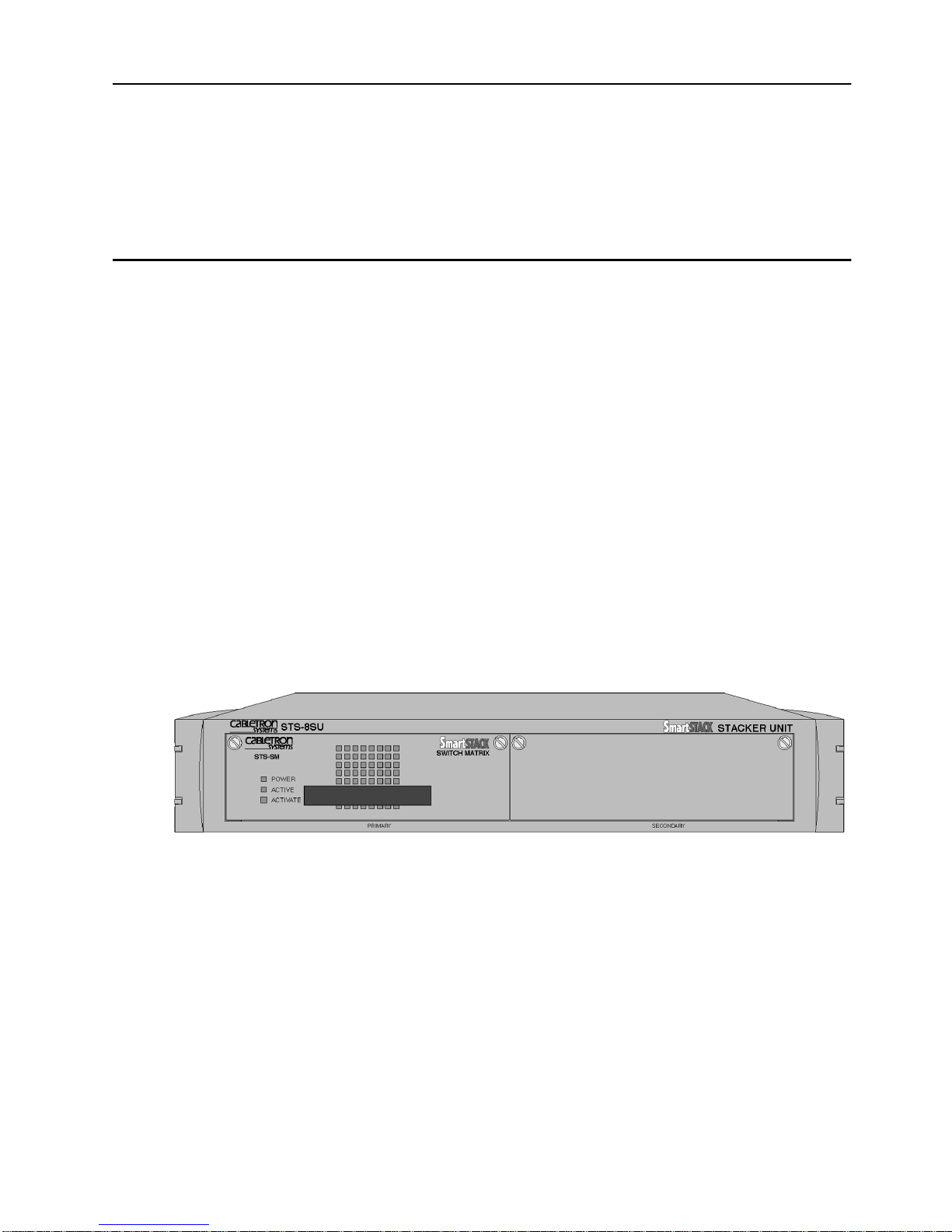
This guide describes how to install and use the STS-8SU External Stacker Unit, a
dedicated switch stacker unit that allows you to connect up to eight switches. Also
described is the SmartStack STS-SM Switch Matrix , that can be install ed in the
STS-8SU Stacker to providing increased network reliability.
Figure 1. Front View of the SmartStack STS-8SU Stacker
SmartStack STS-8SU & STS-SM Installation and User Guide Overview and Specif ic ations
Page 11

2
Smar tStack STS-SM Switch Matrix
The standard configuration of the STS-8SU External Stacker Unit consists of the
STS-8SU chassis itself and one SmartStack STS-SM switch matrix.
The SmartStack STS-SM Switch Matrix includes a fan, power supply, control
LEDs, and complete logic circuitry. The SmartStack STS-8SU Stacker needs only
one SmartStack STS-SM to operate, but has another slot available for a s econd unit.
If two units are used, the SmartStack STS-8SU Stacker runs with an online
(primary) unit installed in the left slot and an offline (secondary) unit in stalled in
the right slot. If the primary unit should fail, operation is switched to the secondary
unit by automatic logic control. The units can be also be switched manually using
the ACTIVATE push button on the front panel.
SmartStack STS-8SU & STS-SM Installation and User Guide Overview and Specifications
Page 12

Features and Specifications
This section lists the features and specifications for th e STS-8SU External Stacker
Unit.
Features
The SmartStack STS-8SU Stacker has the following features:
Eight I/O stack ports using 50-pin SCSI-2 type connectors (one per port)
•
280 Mbps per port (full-duplex)
•
1.12 Gbps total capacity
•
The ability to route packets between switches
•
Round-robin output port arbitration
•
Each port operates independently and in parallel (except for multicast)
•
3
Replicates multicast packets
•
No processor. Managed by the attached CrossFire 8600 Series Switches or
•
CrossFire 8730 Switches.
Optional redundant hot-swappable units
•
Front access to field-replaceable units
•
SmartStack STS-8SU & STS-SM Installation and User Guide Overview and Specif ic ations
Page 13

4
Specifications
See the following table for the SmartStack STS-8SU Stacker specification.
Specification Value
Rack mount 19 in. rack mount (hardware included) 2 U
Dimensions Width: 43 cm (17”)
Rack mounted width: 48.4 cm (19”)
Depth: 40 cm (15.74”)
Height: 8.76 cm (3.45”)
Power 100 to 240 VAC autosensing.
Frequency 50 to 60 Hz
AC current rating 1.3 A @ 100 VAC; 0.6 A @ 240 VAC
Operating Temperature
Non-operating Temperature
Operating Humidity
Non-operating Humidity
Electromagnetic compatibility
immunity
10 to 40°C (50 to 104°F)
–10 to 70°C (13 to 158°F)
8 to 80% (noncondensing)
8 to 95% (noncondensing)
EN 50082-1
EN 61000-3-2
EN 61000-3-3
Electromagnetic compatibility
emission
FCC part 15, subpart B, Class A
EN55022 Class A
CISPR 22 Class A
Safety IEC 950
UL1950
CSA C22.2 No. 950
EN60950
Table 1. SmartStack STS-8SU Stacker Unit Specifications
SmartStack STS-8SU & STS-SM Installation and User Guide Overview and Specifications
❏
Page 14

2. Switch Stacker Theory of Operation
This chapter explains how SmartStack Switch Stacker equipment improves
network performance.
Switch Stacker: A Unique Concept
Any of the Token Ring switches can be stacked together. The switches in the stack
combine to form a single unit. You can stack two to eight switches and manage
them as a single entity. All of the switches in th e stack must, however, run the same
switch software version.
There are two ways of config uring the switch—as a single stand-alone unit or as a
logical combination of up to eight units. This logical combination of units is called
a
switch stack
.
5
A switch stack can be created in three di fferent ways. The simplest configu ration is
a back-to-back stack, in which two switches are connected directly using the
SmartStack STS-LM Link Module and a stacker link cable.
You can also connect up to five switches by using the SmartStack STS-5SU
Internal Stacker Module. You install this module in one of the switches in the stack,
and then you connect the other switches to it using the SmartStack STS-LM Link
Module and cables.
A stack can also consist of up to eigh t switches, con nected by the SmartStack STS8SU Stacker Unit. In this case, you connect each switch in the stack to the switch
stacker using SmartStack STS-LM Link Module and cables.
When a switch is turned on, it runs a set of self-test diagnostics. After the
diagnostics, the sw itch runs a
sense if the switch is cabled to other switches or to the Sm art Stack ST S- 8S U
Stacker Unit. If the switch discovers other switches, a stack is formed
automatically. If no other switches are detected during the stack discovery mode,
the switch starts operating as a stand-alone unit.
You will not need any special tools, extra software, or expensive equipment to form
a stack of switches. See Chapter 4, “Installation” fo r d etails on how to co nnect the
stack equipment.
stack discovery mode
. The discovery mode is used to
SmartStack STS-8SU & STS-SM Installation and User Guide Switch Stacker Theory of Operation
Page 15

6
Stack Features
Single image management for the entire stack (less devices to manage)
•
Management applications represent the stack as a single device
•
— Simple GUI management
Single SNMP image for the entire stack
•
— Eas ier to customize SNMP applications
Distributed intelligence between the units of the stack
•
— Shared learning
— Shared management information
Hot-swappi ng of stack units
•
— If a unit should fail, the other units continue operating as a stack.
— Switches form or reform into the stack.
SmartStack STS-8SU & STS-SM Installation and User Guide Switch Stacker Theory of Operation
Page 16

Creating a Switch Stack
You can create a stack of up to eight switches using the SmartStack STS-8SU
Stacker Unit. The following sections describe how this stack is formed.
SmartStack STS-8SU Stacker Unit Description
The STS-8SU Stacker unit is an eight -port switch matrix interface, that can con nect
up to eight SmartStack Token Ring switches. Each SmartStack Token Ring switch
will discover whether it is connected to a switch stacker unit and whether there are
other SmartStack Token Ring switches connected to the switch stacker. The
connected switches and the switch stacker unit will combine logically to form a
stack.
The stacker itself, as well as any of the stacked switches, can be either on or off
when you connect or disconnect a switch in the stack. A proprietary shielded ca ble,
one meter in length, with 50-pin SCSI-2 type connector s is used to connect the
stacker equipment. The cable has
switch stacker or to the SmartStack Token Ring switches. The cable is plugged
directly into a stack port I/O connector on the back of the STS-8SU External
Stacker Unit. The other end is plugged into the SmartStack STS-LM Link Module
interface card that is installed in the expansion slot on the back panel of the switch.
crossover
7
wiring—either end can connect to the
For a description of the features and physical specifications of the STS-8SU
External Stacker Unit, see Chapter 1, “Overview and Specifications”. For details
on the installation of the STS-8SU External Stacker Unit, see Chapter 4,
“Installation”.
Forming a Multi-Unit Switch Stack
When you turn on the switches, they run a set of self-diagnostics. After the
diagnostics, the switches run a stack discovery mode. During this mode, if two or
more switches are co nnected to a SmartStack STS-8SU Stacker Unit, the switches
will sense the connection and combine logically to create a stack configuration.
As soon as stack discovery mode has finished, two things happen:
1. Each switch is assigned a
The box number is determined by the port number on the switch stacker. For
example, the switch that is plugged into port 3 on the SmartStack STS-8SU
Stacker Unit receiv es th e box number 3. The box nu mber remains the same for
the switch as long as it is plugged into the same port. If a switch is connected to
another port, the box number for that switch will change to correspond to the
new port numb er.
box number
.
SmartStack STS-8SU & STS-SM Installation and User Guide Switch Stacker Theory of Operation
Page 17

8
2. All of the switches in the stack are set to
The parameters that must share v alues on all of the switches in the s tack are the
inter-box parameters
assigned as the source or
switch is selected as follows:
If all of the switches in the stack have the same configuration information
•
(the switches use only default values or have been configured to use the
same values), the switch that is plugged into the
the stacker is selected as the provider of the inter-box parameters.
If the switches in the stack have different settings for the inter-box
•
parameters, the configuration must be changed so that the settings are the
same on all of the switches. To do this, you have to select which of the
switches in the stack should provide the inter-box parameters for the entire
stack. See “Pro vider of Inter-b ox Parameters” on page 11 for information on
how to do this.
(listed on page 9). One of the boxes in the stack is
provider
of these shared parameters. The provider
some configu ration informat ion.
share
lowest numbered port
on
SmartStack STS-8SU & STS-SM Installation and User Guide Switch Stacker Theory of Operation
Page 18

Inter- box Parameters
When a stack is formed, some configuration information of the different switches
in the stack must start using the same settings. These settings are the inter-box
parameters. The stack operates as a single entity when all of the switches in it use
the same inter-box parameters.
The following is a list of the inter-box parameters. These parameters are accessed
from the console configuration menus and screens. The screens and menus are
described in the user documentation supplied with the SmartStack Token Rin g
switches.
9
Switch Configuration
•
— System Name
— System Location
—System Contact
VLAN Parameter Configuration for BRF
•
— VLA N Nam e
— State
—MTU
— Brid ge Nu mber
— 802.1Q VLAN ID
— LAA VLAN MAC Address
VLAN Parameter Configuration for CRF
•
— VLA N Nam e
screen
screen
screen
— Parent VLAN
— State
—Ring Number
—Bridging Mode
— Max ARE Bridge Hop Count
— Ma x STE Bridge Hop Count
— TS Connection
SmartStack STS-8SU & STS-SM Installation and User Guide Switch Stacker Theory of Operation
Page 19

10
IP Configuration
•
— IP Address
—Default Gateway
— Subnet Mask
—IP State
SNMP Configuration
•
— All parameters on this screen.
Spanning Tree for BRF
•
— All parameters on this screen.
Spanning Tree for CRF
•
— All parameters on this screen.
Password
•
— All parameters on this menu.
menu
screen
screen
screen
screen
Console Configuration
•
— All parameters on this menu.
Syslog Daemon
•
— All parameters on this screen.
screen
menu
SmartStack STS-8SU & STS-SM Installation and User Guide Switch Stacker Theory of Operation
Page 20

11
Provider of Inter-box Parameters
In order for a stack to operate as a single entity, the stack must use a set of inter-box
parameters. If all of the switches in the stack contain the same configuration
information, the s witch t hat ha s the l owest box nu mber (i s pl ugged in to the l owe stnumbered stacker link port on the STS-8SU External Stacker Unit) becomes the
provider of the inter-box parameters. If the parameters are different in any of the
switches trying to form the stack, the provider of inter-box parameters is
determined as described below:
If you connected switches before you turned them of, a message will be
•
displayed on the console screen as the s tack tries to form. At this point, because
there will be different configuration information in at least two of the boxes, a
temporary split-stack (two logical stacks) is formed. The units stay in a splitstack configuration until the warning message is cleared.
The message is as follows:
WARNING: The units trying to form a Stack have different
configurations. Please select a unit as the Stack's
configuration provider by briefly pushing the SysReq (System
Request) button on that unit. (This feature gives you the
option of selecting which unit you want to use as a base for
the Stack parameters).
Once the system request button is pushed on one of the switches, that unit
becomes the stack provider and the other switches will replace their stack
related configuration parameters with the parameters of the provider . Note that
the system request button is unlabeled.
The following applies to a back-to- back stack, co nsisting of two s witches that
•
each has a SmartStack STS-LM Link Module installed:
If you turn on two switches in a back-to-b ack st ack before yo u conn ect them,
they will continue to perform their stand-alone internal switching functions.
While the normal internal switching functions are still operating, a split-stack
will be formed. Once the split-stack is formed, the console displays the
warning message requiring a system request. Pushing the system request
button on one of the switches will give the stack the inter-box parameters of
that switch and allow the stack forming to continue.
If you add switches to an existing stack, the inter-box parameters in the
•
existing stack will be used.
SmartStack STS-8SU & STS-SM Installation and User Guide Switch Stacker Theory of Operation
❏
Page 21

12
SmartStack STS-8SU & STS-SM Installation and User Guide Switch Stacker Theory of Operation
Page 22

3. Preparing for Installation
Before installing the SmartStack STS-8SU External Stacker Unit, read this chapter
carefully.
Safety Recommendatio ns
Follow these guidelin es to ensure gener al saf ety during and aft er the inst al la ti on:
Keep the chassis area clear and dust-free during and after installation.
•
Keep tools away from walk areas where you and others could trip over them.
•
Do not perform any action that creates a potential hazard to people or makes
•
the equipment unsafe.
13
➽
➽
Safety with Electricity
Follow these guidelines when working on equipment powered by electricity.
Warning:
jewelry (including rings , necklaces, bracelets and watches). Metal objects will heat
up when connected to power and ground and can cause serious burns or weld the
metal object to the terminals.
Warning:
periods of lightning activity. Read the installation instructions before you connect
the system to its power source.
To turn
cord. There is no ON/OFF switch.
•
Before working on equipment that is connected to power lines, remove
Do not work on the system or connect or disconnect cables during
the STS-8SU External Stacker Unit, you must disconnect the power
off
Locate the emergency power-off switch for the room in which you are
working. Then, if an electrical acciden t occurs, you can act quickly to tur n of f
the power.
Before working on the system, unplug the power cord.
•
Disconnect all power before doing the following:
•
— Installing or removing a chassis
— Working near power supplies
— Performing a hardware upgrade
Do not work alone if potentially hazardous conditions exist.
•
SmartStack STS-8SU & STS-SM Installation and User Guide Preparing for Installation
Page 23

14
Never assume that power is disconnected from a circuit. Always check.
•
Look carefully for possible hazards in your work area, such as moist floors,
•
ungrounded power extension cables, and missing safety grounds.
If an electrical accident occurs, proceed as follows:
•
— U se caution; do not become a victim yourself.
— Unplug the power cord(s).
— If possible, send another person to get medical aid. Otherwise, assess the
condition of the victim and then call for help.
— Determine if the person needs rescue breathing or external cardiac
compressions; then take appropriate action.
Preventing Electrostatic Discharge Damage
Electrostatic discharge (ESD) can damage equipment and impair electrical
circuitry. It occurs when electronic components are improperly handled and can
result in complete or intermittent failures. Always follo w ESD-prevention
procedures when removing and replacing components. Ensure that the chassis is
electrically connected to earth ground using an ESD mat or a ground wire. Wear an
ESD-preventive wrist strap, ensuring that it makes goo d s kin co ntact. To safely
channel unwanted ESD voltages to ground, connect the clip to an unpainted surface
of the chassis frame. To properly g uard against ESD damage an d shocks , the wrist
strap and cord must operate effectively. If no wrist strap is available, ground
yourself by touching the metal part of the chassis.
➽
SmartStack STS-8SU & STS-SM Installation and User Guide Preparing for Installation
Caution:
which should be between 1 and 10 MΩ.
For safety, periodically check the resistance value of the antistatic strap,
Page 24

Site Requirements
Following are the site requirements for installation.
Environment
Choose a clean, dust-free, preferably air-conditioned location. Avoid direct
sunlight, heat sources, or areas with high levels of EMI (Electromagnetic
Interference).
Chassis Accessibility
Make sure the front and rear panel of the equipment is accessible so that you can
monitor the LED indicators and access the control switches. Leaving enough
clearance at the front and rear will also allow easier cabling and service.
Cooling and Airflow
15
➽
Two fans, which are located at the rear of the switch, cool the interior by drawing
air through vents on the sides and forcing heated air out through holes in the rear.
If the internal temperature exceeds 50°C (1 12°F), a temperature error is repor ted to
the console.
Caution:
that exceeds the maximum recommended ambient temper ature of 40°C (104°F). T o
preven t airflo w rest riction, yo u must allo w at least 7.6 cm (3 ”) of clearan ce around
chassis openings for proper airflow.
To protect the equipment from overheating, do not operate it in an area
SmartStack STS-8SU & STS-SM Installation and User Guide Preparing for Installation
Page 25

16
Power
The source electrical outlet should be installed near the switch, be easily accessible,
and be properly grounded.
➽
➽
➽
Warning:
systems with a power switch, line voltages are present within the power supply even
when the po wer switch is of f an d the po wer cord is co nnected. F or systems without
a power switch, line voltages are present within the power supply when the power
cord is connected.
Warning:
(overcurrent) protection. Ensure that a fuse or circuit breaker no larger than
120 VAC , 15 A U.S. (240 VAC , 10 A international) is used on the phase conduct ors
(all current-carrying conductors).
Warning:
hazard. If the voltage indicated on the label is different from the power outlet
voltage,
Do not touch the power supply when the power cord is connected. For
This product relies on the building’s installation for short-circuit
A voltage mismatch can cause equipment damage and may pose a fire
do not connect the chassis to that receptacle
.
SmartStack STS-8SU & STS-SM Installation and User Guide Preparing for Installation
Page 26

Pac ka ge Co nte nts
Immediately after receiving the equipment, examine all shipping containers and
contents for damage. If any damage has occurred, notify the shipping carrier.
Unpack the unit by removing the packing material and lifting it from its protective
enclosures. Visually examine the equipment and check the container for related
parts and accessories. You should have the following items:
One SmartStack STS-8SU External Stacker Unit with one SmartStack STS-
•
SM Switch Matrix installed.
17
➽
One
•
•
Report any missing parts and any d amage not relate d to sh ipping to yo ur cus tomer
service representative.
Note:
warranty should be shipped in their original packing materials
If you have received your equipment before your site is fully prepared, after
inspection, you should keep all of the components in the original shipping
containers and store them in a physically and environmentally safe place.
When you are ready to begin the installation, please refer to Chapter 4,
“Installation”, for important instructions and directions.
SmartStac k STS-8SU External Stac ker Unit—Ins tallation and User Guid e
(this publication)
One CD-ROM containing the switch software as well as user documentation
in PDF format
Keep the packing materials for future use.
All components returned under
.
❏
SmartStack STS-8SU & STS-SM Installation and User Guide Preparing for Installation
Page 27

18
SmartStack STS-8SU & STS-SM Installation and User Guide Preparing for Installation
Page 28

4. Installation
This chapter contains step-by-step instructions for installing, connecting, and
verifying the operation of the SmartStack STS-8SU External Stacker Unit.
Mounting the Chassis
The STS-8SU External Stacker Unit can be mounted in any st and ard 1 9-inch rack
or cabinet. The installation area should be near a power source and should have
enough room around the front and back panels for cabling and access to controls.
19
➽
➽
➽
Warning:
replace this equipment.
Only trained and qualified personnel should be allowed to install or
Rack or Cabinet Mounting
When mounting the equipment in a closed or multi-unit rack, observe the
environmental guidelines in Chapter 3, “Preparing for Installation”.
Note:
above the switch stacker for three switch units, and enough space below for five
switch units. In order for the stacker link cable to reach all units, the switches must
be cabled in a particular order, as shown in Figure 5 on page 23.
Caution:
that the STS-8SU External Stacker Unit and any other equipment are mechanica lly
stable.
To accommodate a stack of the full eight switch units, leave enough space
The following rack mounting instr uctions need to be ob ser v ed to ensure
SmartStack STS-8SU & STS-SM Installation and User Guide Installation
Page 29

20
The following step s des cri be how to mount the ST S-8S U Ex ter nal St acker U nit in
a rack or cabinet:
1. Remove the brack et co ver s on each side of the STS-8SU Extern al Stacker Unit
to expose the rack mounting brackets. Access the retaining screws by opening
the cap on the front of each bracket cover. Use the Allen key supplied with the
switch stacker to r emo ve the t wo 6 mm Allen scr e ws. When y ou ha v e remo v ed
the screws, push the bracket cover towards the back of the switch and lift the
cover off. Keep the screws for later use.
➽
Figure 2. Exposing the Rack Mounting Brackets
Before continuing with the next step, be sure you have the proper hardware for
mounting the chassis with the exposed brackets to your cabinet or rack.
2. Position the STS-8SU External Stacker Unit, with the exposed mounting
brackets, in the rack or cabinet and slide it up or down until the bracket holes
line up with the rack holes. Attach the chassis brackets to the rack using the
Allen screws you removed above and the nuts supplied with the switch. Close
the cap again to conceal the screws.
Note:
Only fixed brackets are supplied with these units. If you want to install a
sliding pullout mount, you will need to provide the extra mounting hardware.
SmartStack STS-8SU & STS-SM Installation and User Guide Installation
Page 30

Figure 3. Mounting the Switch Stacker in a Rack or Cabinet
21
➽
Table-Mounting
The STS-8SU External Stacker Unit operates at a low noise level, which makes it
suitable for a work area or almost anywhere with a large enough flat surface such
as a table or desktop.
Four self-adhesive pads are supplied with the switch stacker. The pads must be
mounted in the four recesses on the bottom of the unit. When the pads are mounted,
simply place the switch stacker on a clear, level location. Leave enough room
around the switch stacker for ventilation and access to the controls and cable
connectors.
Caution:
equiv alent weight of o ther equipment) directl y on top of another chas sis. More than
three un its on top o f another un it may cause damage to the lower unit.
Due to weight constraints, place no more than three units (or the
SmartStack STS-8SU & STS-SM Installation and User Guide Installation
Page 31

22
Cabling a Stack
The next sections describe how to connect switches to the STS-8SU External
Stacker Unit to form a stack.
➽
Warning:
software to the switch
If you plan to download software to a switch in the stack, download the
before
connecting it to the stack. If the switch is already part
of a stack, disconnect the stack port cable before downloading. Downloading
software (such as changing firmware levels) to an indi vidual switch while it is part
of a stack may cause conflicts within the stack.
Connecting Switches to the Switch Stacker
Up to eight switches can be connected to a single STS-8SU External Stacker Unit.
This configuration requires a stacker link cable and a SmartStack STS-LM Link
Module for each switch. The connection is made through one of the eight I/O stack
ports on the back panel of the STS-8SU External Stacker Unit to the I/O s tack port
on the SmartStack STS-LM installed in the back panel of each SmartStack Token
Ring switch.
All of the I/O ports feature SCSI-2 ty pe connectors. A proprietary cable, the Stacker
Link Cable, is used to connect each switch to the switch stacker. Note that the
switches must be cabled to the switch stacker in a particular order for the switch
stack cable to reach all switches in the stack. Figure 4 shows how to cable the stack.
For selection of power cord
set please refer to the manual
Guide to Oper ations
Figure 4. Connecting the Stack Port Cable to Port 1
on the Switch Stacker
After mounting the switches and the switch stacker in a rack or cabinet, use the
following instructions to cable the units together:
1. Attach one end of the stack port cable to a port the STS-8SU External Stacker
Unit (see Figure 4). Either end of the cable can be used, and yo u do n ot need to
turn off the equip ment. Th e port y ou ch oos e det erm in es the b ox n umb er of t h e
switch in the stack.
SmartStack STS-8SU & STS-SM Installation and User Guide Installation
P2 P4 P6 P8
P1 P3 P5 P7
IG VOLTAGES
TOP COVER MA ONL
BE REMOVED B
AUTORIED PERSONNEL
TE CASSIS MA A VET O POER
SUPPL UNITS . TO REDUCETE RIS OF
ELECTRIC SOC, DISCONNECT TE T O
POER CORDS BEFORE AN SER VICING
CAUTIONARNING
DO NOT CONNECTTE PO ER CORD
UNLESS ALL OPENINGS ARE CLOSED
B BLIND P ANELS
This device complies with Part 15 of the FCC
Rules.Operation is subect to the f ollowing two
conditions.(1) This device may not cause
harmful interference, and (2) this device must
accept any interference received, including
interference that may cause undesired operation.
LISTED
U
U
I.T. E.
R
R
L
L
3C04
C
For selection of power cord
set please refer to the manual
Guide to Oper ations
Page 32

23
➽
Caution:
To avoid bending pins, do not install the stack port cable connector at an
angle. Use extra care to insert the cable connector straight into the socket.
T
T
R
R
LIN
ATTAC
Figure 5. Connecting the Stack Port Cable to the Stack Link
Module on a Switch
2. Attach the other end of the cable to the port connector on the
SmartStack STS-LM Module (see Figure 5).
➽
Note:
You cannot use the SmartStack STS-5SU Stacker Unit instead of the
SmartStack STS-LM Module to form a stack with the STS-8SU External Stacker
Unit.
3. Repeat these steps for each switch in the stack.
Figure 4 shows the switch stacker cabled to eight switches. Three switches have
been mounted above th e switch stacker and five below. The lowest switch has been
connected to port one on the switch stacker and is defined as Box 1. The highest
switch has been connected to port eight and is defined as Box 8.
SmartStack STS-8SU & STS-SM Installation and User Guide Installation
Page 33

24
Box 8
Box 7
Box 6
Box 5
For selection of power cord
set please refer to the manual
Guide to Oper ations
T
T
R
R
LIN
ATTAC
T
T
R
R
LIN
ATTAC
T
T
R
R
LIN
ATTAC
T
T
R
R
LIN
ATTAC
P2 P4 P6 P8
P1 P3 P5 P7
IG VOLTAGES
TE CASSIS MA A VET O POER
TOP COVER MA ONL
SUPPL UNITS .TO REDUCE TE RIS OF
BE REMOVED B
ELECTRIC SOC, DISCONNECT TE T O
AUTORIED PERSONNEL
POER CORDS BEFORE AN SER VICING
CAUTIONARNING
DO NOT CONNECTTE PO ER CORD
UNLESS ALL OPENINGS ARE CLOSED
B BLIND P ANELS
This device complies with Part 15 of the FCC
Rules.Operation is subect to the f ollowing two
conditions.(1) This device may not cause
harmful interference, and (2) this device must
accept any interference received, including
interference that may cause undesired operation.
LISTED
U
U
I.T.E.
R
R
L
L
3C04
C
For selection of power cord
set please refer to the manual
Guide to Oper ations
Box 4
Box 3
Box 2
Box 1
T
T
R
R
LIN
ATTAC
T
T
R
R
LIN
ATTAC
T
T
R
R
LIN
ATTAC
T
T
R
R
LIN
ATTAC
Figure 6. Back View of the Switch Stacker Cabled to Eight Switches
SmartStack STS-8SU & STS-SM Installation and User Guide Installation
Page 34

Checking the Installation
Before you turn on the SmartStack stack equipment, inspect the equipment
thoroughly. Verify that all cables are installed correctly. Check cable routing to
make sure no cable will be damaged or create a safety hazard. Be sure all equipment
is mounted properly and securely.
Applying Power
25
➽
➽
➽
Warning:
Power is on when the unit is plugged into a power source
Important:
There are no ON/OFF switches on the STS-8SU External Stacker Unit.
.
All switches in a stack must use the same software version. If any
switch uses a different software version, a warning message will appear on the
switch console, and the switch will not join the stack.
There are no user serviceable parts inside the STS-8SU External Stacker Unit or the
SmartStack Token Ring switch. Any internal upgrades or service should be
performed by qualified personnel
Warning:
Do not touch the power supply when the power cord is connected. Line
only
.
voltages are present within the power supply when the power cord is connected.
P2 P4 P6 P8
P1 P3 P5 P7
For selection of power cord
set please refer to the manual
Guide to Oper ations
Figure 7. The AC connector for the Primary Power Supply Unit
is on the right of the STS-8SU Stacker unit back panel
Use the following steps to power on your equipment.
1. Make sure that you are using the correct power source.
2. Using the supplied power cables, plug the female end of the cable into the AC
receptacle on the STS-8SU External Stacker Unit switch stacker or the switch.
On the STS-8SU External Stacker Unit, the A C connector fo r the primary unit
•
is at the right on the back panel. The AC connector for the secondary
(redundant) unit is at the left on the back panel (see Figure 7).
SmartStack STS-8SU & STS-SM Installation and User Guide Installation
IG VOLTAGES
TOP COVER MA ONL
BE REMOVED B
AUTORIED PERSONNEL
TE CASSIS MA A VET O POER
SUPPL UNITS . TO REDUCETE RIS OF
ELECTRIC SOC, DISCONNECT TE T O
POER CORDS BEFORE AN SER VICING
CAUTIONARNING
DO NOT CONNECTTE PO ER CORD
UNLESS ALL OPENINGS ARE CLOSED
B BLIND P ANELS
This device complies with Part 15 of the FCC
Rules.Operation is subect to the f ollowing two
conditions.(1) This device may not cause
harmful interference, and (2) this device must
accept any interference received, including
interference that may cause undesired operation.
LISTED
U
U
I.T. E.
R
R
L
L
For selection of power cord
3C04
C
set please refer to the manual
Guide to Oper ations
Page 35

26
T
T
R
R
LIN
ATTAC
Figure 8. The A C Connecto r for the Primary P ow er Supply Unit at the Right on
the SmartStackToken Ring Switch Back Panel
3. Plug the male end of the power cord(s) into a properly grounded electrical
outlet.
4. On the STS-8SU External Stacker Unit, verify that the POWER LED is on. If
the LED does not turn on, check that the power outlet is functioning correctly.
➽
➽
5. On the switch, check that the PWR LED is on. If the LED does not turn on,
check that the power outlet is function ing correctly. The switch runs a series of
self-test diagnostics during the power-up c ycle. The DIA G LED is on during the
diagnostics and turns off when the self-test is complete.
6. At the completion of diagnostics, the front panel LEDs should turn on
indicating the status of the configuration. The LEDs and their meanings are
described in the documentation supplied with the switch.
Note:
If the switch f ails to po wer up correctly or if it encounters an y unreco verable
error, the ERR LED will be on or flashing. If the ERR LED is on, refer to the
documentation supplied with the switch for troubleshooting hints.
Note:
STS-8SU External Stacker Unit or SmartStack STS-SM Switch Matrix
modules do not run power-on diagnostics and have neither DIAG nor ERR LEDs.
When the STS-8SU External Stacker Unit chassis is turned on, the POWER LED
and the fan should also turn on. If they do not turn on, this indicates a fault.
SmartStack STS-8SU & STS-SM Installation and User Guide Installation
Page 36

STS-8SU External Stacker Unit Control Panels
The following tabl es list and provide a d escription of the con nectors, switches, push
buttons, and status LEDs on the STS-8SU External Stacker Unit.
Front Panel
Table 2 and Table 3 list the front panel controls on the STS- 8S U Ex ter nal Stacker
Unit.
Push Buttons
Name Description
ACTIVATE When the ACTIVATE push bu tton i s pr essed o n an off line
module, it will go online and the ACTIVE LED will turn
on. The second module will go offline and its ACTIVE
LED will turn off. There is no effect if it is pressed on an
online m odule.
The ACTIVATE push button is recessed, and you will need
a pencil or other pointed device to activate the switch.
27
Table 2. Front Panel Switch
Status LEDs
Name Color Description
POWER Green Indicates that the unit is receiving power.
ACTIVE Green The LED is lit on the active unit and off on
the inactive unit.
Table 3. Front Panel LEDs
SmartStack STS-8SU & STS-SM Installation and User Guide Installation
Page 37

28
Back Panel
Table 4 and Table 5 list the back panel controls on the STS-8SU External Stacker
Unit.
Connectors
Name Description
P1 to P8 SCSI-2 type connectors for connecting sw itches to the
switch stacker.
AC power
connector
Standard AC power connectors. The power receptacle on
the right of the stacker back panel is for the primary power
supply.
Table 4. Back Panel Connectors
Status LEDs
Name Description
P1 to P8
(unlabeled)
Ta ble 5. Back Panel LEDs
The port LED turns on to indicate that a connection to the
attached switch has been established.
STS-8SU External Stacker Unit Chassis Description
You can install two SmartStack STS-SM Switch Matrix Modules in a SmartStack
STS-8SU secondary unit for redundancy. Each unit contains complete packet
switch circuitry, power supply and a cooling fan. The units are front accessible and
field replaceable.
The SmartStack STS-8SU Stacker Unit has an I/O backplane and connectors for
two SmartStack STS-SM Switch Matrix Units. On the outside panels I/O
connectors and indicators (one per port) are available for connecting switches.
The chassis is 2 RU (Rack Units) in height. The width is 19 inches (48.4 cm) for
rack mounting. The chassis depth is approximately 14 inches (35.5 cm).
SmartStack STS-8SU & STS-SM Installation and User Guide Installation
Page 38

STS-SM Switch Matrix
This section explains how to install a SmartStack STS-SM Switch Matrix Unit in
the STS-8SU External Stacker Unit. For a detailed explanation of the SmartStack
STS-SM Switch Matrix Unit, see section “STS-SM Switch Matrix Unit Operation”
later in this chapter.
29
➽
Figure 9. View of the STS-8SU Sta cker Unit wit h a SmartStack STS-SM Switch
Matrix Module in the Left (Primary) Position
SmartStack STS-SM Switch Matrix Unit Installation
A SmartStack STS-SM Switch Matrix Unit can be inst alled in either or both slots
of the STS-8SU External Stacker Unit. If a unit fails, it can be easily replaced by
the user. The following describes the procedure for adding or replacing a
SmartStack STS-SM Switch Matrix Unit.
Note:
swapped while power is on and while it is online. However , if possible, try to avoid
swapping an online unit during very heavy traffic. The switching time from an
online to an offline unit is very short, but during extremely heavy traffic it could
cause an interruption of data. When it is necessary to remove an online module, if
possible, switch it offline when there is little or no traffic.
Use the following steps for installing or replacing a SmartStack STS-SM Switch
Matrix Unit. If you are installing a module into an open slot proceed to step 5.
SmartStack STS-SM Switch Matrix Units are hot-swappable. A unit can be
1. If the slot is covered with a blank plate, remove the screw located at the top
center and then remove the plate. (Reverse the procedure to install a cover
plate).
2. If removing a unit, switch it offline and turn off the unit. (See the note on this
page concerning pow er).
3. Remove the screw located at the top center on the front of the unit.
SmartStack STS-8SU & STS-SM Installation and User Guide Installation
Page 39

30
4. Using the handle on the front of the unit, pull the unit straight out from the
chassis.
➽
Warning:
The unit may be firmly seated in the chassis; if so, you may need to ex ert
some reasonable force to disengage the unit.
5. Insert the unit into the open slot. Place the bottom of the unit against the bottom
of the slot and slide the unit into the slot. You should feel some resistance as the
unit connector mates with the chassis connector . If you feel solid resistance, pull
the unit back a little and try again while moving the unit slightly to the left or
right until you feel the two connectors engage. After the connectors start to
engage you should be able to i n sert t he u nit approximat ely half an inch further
and then you should f eel hard resistance. The connector s should be seated at that
point.
6. Connect the power cord to the unit.
7. To switch the unit online, press the ACTIVATE push button.
Figure 10. Inserting a Secondary Unit into the STS-8SU Stacker unit Chassis
STS-SM Swi t ch Mat rix Unit Op e ra t ion
There are two slots for the SmartStack STS-SM Switch Matrix Units in the STS8SU External Stacker: a primary slot (usually online) , and a secondary slot (usually
offline). The units are hot-swappable. When a secondary unit is installed, it
functions as a redundant unit that can be switched o nl ine if the primary unit fails.
The primary slot is at left seen from the front of the stacker.
The units can switch over automatically or manually. Automatic switch-over
occurs if power fails on the active unit or if a primary to secondary switch-over is
initiated through any attached switch. Switch-overs can also be initiated manually
using the ACTIV AT E fro nt p anel pu sh button on t h e Sm art S tack S TS-SM Switch
SmartStack STS-8SU & STS-SM Installation and User Guide Installation
Page 40

31
Matrix Unit. Pressing the push button on the offline unit forces it online while the
other unit switches offline. The newly activated unit assumes the switching
functions. The following sections contain detailed descriptions of unit switchovers.
Automatic Switch-Over from a SmartStack STS16-20RM
Automatic switch-over is initiated when a switch senses th at the primary unit has
failed. When a failure is detected, any switch can request the STS-8SU External
Stacker Unit to switch from the primary unit to the secondary unit. When the
secondary unit is online, no further switch-over requests are generated by the
switches (switches cannot initiate switch-over from the secon dary unit to the
primary unit). This one-time switch-over prevents unit swap oscillations.
Each SmartStack switch periodically sends a packet to itself (self-ping). As long as
the packet returns, the online SmartStack STS-SM Switch Matrix Unit is
considered functional. If the self-ping packets do not arrive after a time-out, the
online unit is considered faulty and the SmartStack Token Ring switch requests a
unit switch-over. The request is via a software controlled request line in the stack
port link. If a switch-o ver is requested and t he primary un it is online, the S TS-8SU
External Stacker Unit will switch to the secondary unit (if present).
Manual Switch-Ove rs
A manual switch-over is one that is initiated by the operator. Each unit has an
ACTIVATE push butt on on the front panel . Pressing this push button on the offline
unit turns it online (active) while the unit that was online is forced offline. Pressing
the push button on the online unit has no effect.
Switch-Over Impact on Traffic
During a controlled s witch-over, data transf er management helps prevent ing errors.
A controlled swit ch-over is one activ ated by a swit ch (automatic) or by pressing the
push button (manually by the operator).
An uncontrolled switch-over occurs when the online unit is removed or turned off.
Several packets could get corrupted during this time.
If the STS-8SU External Stacker Unit ports are idle during unit switch-over, no
packets will be corrupted.
Turning a unit on or off, or moving a unit will have the following effects:
Simultaneous power-up
time, the primary unit will go online. The secondar y unit has a power-up delay that
allows the primary unit to go online first.
—When both units are installed and turned o n at the same
SmartStack STS-8SU & STS-SM Installation and User Guide Installation
Page 41

32
Hot insertion
—If a second unit (primary or secondary) is inserted and turned on
after the other unit has gone online, nothing will happen; the new unit will stay
offline and the other will stay online.
Online unit turned off or removed
—Whether primary or secondary, the
remaining unit will detect the other's absence and go online. (Packet errors may
occur with this type of switch-over).
Both ACTIVATE push buttons pressed simultaneous ly
—Whichever push
button is pressed first will cause the unit to go online and force the other offline. In
the unlikely case of a tie, the primary unit will go online.
SmartStack STS-8SU & STS-SM Installation and User Guide Installation
Page 42

Installing a SmartStack STS-LM Link Module
The following sections explain the installation and use of the SmartStack STS-LM
Link Module Module, t hat yo u can us e to co nnect tw o or m ore s wi tc hes in a stack.
The SmartStack STS-LM is a single-port interface module that is installed into the
back panel of the switch. When two switches are connected together by the
SmartStack STS-LM Module and the STS-8SU External Stacker Unit, the switches
combine to form a stack.
Installing the STS-LM Link Module
The module is inserted in its expansion slot as shown in Figure 11.
33
➽
➽
➽
Figure 11. Inserting an SmartStack STS-LM Link Module
Caution:
that the power is off before installing or removing a SmartStack STS-LM Mo dule.
If the power is on, the equipment may be damaged.
Caution:
Module. Do not touch cable connector pins when the other end is plugged in.
Damage from static electricity may result.
Caution:
must line up evenly with the connector inside the expansion slot. Misalignment may
bend the connector pins. When ins erting the SmartStack STS-LM Mod ule into the
expansion slot, be sure that the board is level and that the left and right sides slide
evenly into the slot.
SmartStack STS-LM Modules are
Do not touch the components or connectors on the SmartStack STS-LM
During installation, the connector on the SmartStack STS-LM Module
hot-swappable. Always be sure
not
SmartStack STS-8SU & STS-SM Installation and User Guide Installation
Page 43

34
Use the following steps when installing an SmartStack STS-LM Link Module
module into the expansion slot on the back panel of a switch.
1. Turn off power to the switch.
2. If a blank plate covers the back panel slot, remove it by unscrewing its two
attachment screws.
3. To prevent possible static damage to the module, hold it by its edges only. Be
careful not to touch the top or bottom.
4. Slide the module into the slot evenly, taking care to line up the edges with the
guides.
5. Seat the module by pressing the front of the module with your thumbs.
6. Secure the module to the chassis by tightening the thumb (panel) screws at the
left and right edges on the expansion module. Do not overtighten the screws.
7. Turn on the switch.
➽
SmartStack STS-LM Link Module Module Cables
The SmartStack STS-LM Module has a 50-pin SCSI-2 connector designed to
accept the Stacker Link Cable. Note that the Stacker Link Cable is designed
specially for use with SmartStack stacks. You cannot use a standard SCSI cable.
Caution:
an angle. Use extra care to insert the cable connector straight into the SmartStack
STS-LM connector.
To avoid bending pins, do not install the stacker link cable connector at
❏
SmartStack STS-8SU & STS-SM Installation and User Guide Installation
Page 44

5. Accessing Switch Management
The switches can be configured in two ways:
35
1.
Using the switch console
You can access the switch console interface
— directly, by connecting a VT100 terminal emulator to the RS-232 port
— remotely, via Telnet.
2.
Using SNMP based gra phical management applications
— The SmartS tack Token Ring Sw i tch Manage r
— Other Simple Network Mana gemen t Pr ot oco l (S N MP) bas e d app licat ion s
Overview
This chapter describes how to access the switch console via the MANAGEMENT
port.
Network management app lications (in-band management) are b eyond th e scope of
this guide. However, note that to be able to manage the switch by the network
management applicati on via SN MP, you w ill have to configure a few set tings fi rst
in the switch console. These are typically the IP Address, SNMP Community, and
Trap Receiver.
.
labelled MANAGEMENT.
OR
:
Refer to the information on console and Telnet sessions in the documentation
supplied with the SmartStack Token Ring Switche s.
SmartStack STS-8SU & STS-SM Installation and User Guide Accessing Switch Management
Page 45

36
Connecting the Console
The two following subs ectio ns explai n h ow to conn ect to the switch console. You
can connect directly or via a modem. For detailed information on cabling and pins,
see the user documentation supplied with the switch.
Connecting a Terminal Directly to the MANAGEMENT Port
1. Connect one end of a crosso ver TIA/EIA- 232 cable (commonly kn own as a RS-
232 cable) to the MANAGEMENT port. This is a male DB-9 connector
configured as a DTE (Data Terminal Equipment) device.
2. Connect the other end of the cable to a PC or another DTE device.
OR
1. Attach a null-modem adapter to the MANAGEMENT port.
2. Attach a straight-through modem cable to the null-modem adapter.
Connecting to the MANAGEMENT Port Using a Modem
1. Connect one end of a straight-through TIA/EIA-232 modem cable to the
MANAGEMENT port. This is a male DB-9 connector configured as a DTE
device.
2. Connect the other end of the cable to a modem.
See Figure 12 for a view of the cable connection to the front panel of the switch.
Figure 12. View of the Management Console Connection
3. Use these default v alues to set the conf igurati on parameters on your co nsole for
interfacing to the switch.
4. At power on (cold boot), the switch performs a series of self-test diagnostics
verifying that hardware comp onents are functioning. An example of the self-test
diagnostic screen is shown later in this chapter.
SmartStack STS-8SU & STS-SM Installation and User Guide Accessing Switch Management
Page 46

Specification Value
Baud rate 2400, 4800, 9600 (default), 19200,
38400, 57600
Parity None
Data bits 8
Stop bits 1
Handshaking None
Terminal emulation VT100
Duplex Full
37
Soft flow control (XON/XOFF) Off (input and output)
Hard flow control (RTS/CTS) Off
Autobaud upon break On
Line wrap On
Screen scroll On
CR translation CR
Backspace (BS) translation Destructive
Break length (milliseconds) 350
Enquiry (ENQ) Off
EGA/VGA true underline Off
Terminal width 80
ANSI 7 or 8 bit commands 7
Microsoft Windows™ terminal
emulation
Table 6. Default Console Configuration Settings
SmartStack STS-8SU & STS-SM Installation and User Guide Accessing Switch Management
Disable the “Use Function, Arrow , and
Ctrl Keys for Windows” option
located in the Terminal Preference
menu
Page 47

38
Communication Problems
If the diagnostic list does not appear, or is garbled, try adjusting the baud rates
between the console and the switch by using the Autobaud routine within the
switch. To do this, press the reset button on the front of the switch and wait for the
internal diagnosti cs to fi nish (t he DIAG LED turns o ff). The reas on for th e reset i s
that in case the switch’s Autobaud routine is disabled, resetting it will set it to its
default mode,
Autobaud enabled
Depending on the type of th e console, there are several cons ole command keys that
will potentially initiate the Autobaud routine in the swi tch. Fou r of these keys are
RETURN
, the combination keys
After the DIAG LED turns off, try one of the command keys at the console, and
press it repeatedly. If there is no res pon se, wait several secon ds and ag ain, pr ess it
repeatedly. If necessary, perform the same routine using the other command keys.
If this does not work, and there is a garbled output on the screen, try push ing the
unlabeled system request button on the switch. As soon as garbled characters
appear, press the console’s
other command keys as necessary.)
.
ALT-B
RETURN
, the
BREAK
key, and
ESC
.
key twice in rapid succession. (Again, try the
If the problem remains, try the following step s:
1. Check all of the cable connections.
2. Check the baud rate at the console’s set up screen; if it is not set to 9600, try this
setting.
3. Try setting the console baud rate to different values up or down, and pressing
RETURN
for each selection.
4. If you are using a terminal emulation program, try exiting the program and
restarting.
5. If you still can not get the connection to work, see Chapter 7, “Getting in Touch
With Technical Support”.
SmartStack STS-8SU & STS-SM Installation and User Guide Accessing Switch Management
Page 48

Diagnostic Screen
The dia gnostic self-test dis plays two different screens, depending on whether you
perform a cold boot ( power-on cycl e with full diagnostics ), or a warm bo ot (a reset
without full diagnostics). The warm boot contains por tions of the complete cold
boot lis t .
39
The following is an
example
of a diagnostic screen during a boot process. The
actual screen may vary depending on, for example, hardware, options , and software
version levels:
BootStrap Firmware v2.3, Copyright 1996-1998
- Initiating bootstrapping sequence.
- Boot image integrity check...Passed.
- Control transferred to boot process.
Boot Firmware (Phase II) v2.3
- Program memory test........Passed.
- Relocating main image to
DRAM.......................................Done.
- Main image integrity check...succeeded.
- Control transferred to main process.
- Starting Power On Self Test Diagnostics.
- Network memory test 32-bits........Passed.
- Network memory test 16-bits........Passed.
- Network memory test 8-bits........Passed.
- Port register and memory test.....................Passed.
- Single port loopback test.....................Passed.
- All ports linked loopback test.....................Passed.
- Port MAC test.....Passed.
- Completed Power On Self Test Diagnostics.
System Software Version 4.0.0, Copyright 1994-1999.
System started on Mon. June 21, 1999 14:30:03
8 Megabytes System memory
2 Megabytes Network memory
- Initialization started
- File system initialized
- System temperature is within safe operating levels
- Checking file system integrity
- Warmboot initialization started
- LAN ports detected:
- RJ-45 Token Ring: 1 2 3 4 5 6 7 8 9 10 11 12 13 14 15 16 17 18 19 20
- StkPort : 29
- Initializing Ports: 1 2 3 4 5 6 7 8 9 10 11 12 13 14 15 16 17 18 19
20 29
- Initializing system address table
SmartStack STS-8SU & STS-SM Installation and User Guide Accessing Switch Management
Page 49

40
- System entering stand-alone mode
- System initialization complete
- Enabling port: 1 2 3 4 5 6 7 8 9 10 11 12 13 14 15 16 17 18 19 20 29
Press RETURN key to activate console...
Depending upon which tests have run, verify that all diagnostics have passed and
that the ERR LED is off. If the ERR LED is on, read the screen to determine which
test failed. Also see Chapter 7, “Getting in Touch With Technical Support”, to help
determine the cause.
At the end of the boot messa ges, you shou ld be prompted t o press
RETURN (ENTER)
The following greeting screen of the switch console manager should appear:
.
At the top level screen, press
contents of the main menu, the submenus and screens are described in subs equ ent
chapters. The information in these chapters includes configuring, monitoring, and
viewing statistics on the switch.
➽
Note:
If you have forgotten the password, you can delete it by pressing the
unlabeled system request button on the front panel of the switch for one second.
Then release it and select
the
Read-Only
SmartStack STS-8SU & STS-SM Installation and User Guide Accessing Switch Management
and the
ENTER (RETURN
) to enter the main menu. The
Point 4. Clear the system passwo rd
Read/Write
password.
. This will clear both
❏
Page 50

6. Switch Configuration
This chapter explains how to set up and modify the stack configuration of the
switches using a VT100 console attached to the switch directly or via a modem
connection. The switch configuration can also be modified from a remote VT100
console via a telnet session.
For information on how to connect the console, see Chapter 5, “Acces sing Switch
Management”.
General Guidelines
To work within the console menus and screens, follow these guidelines:
To select an item on a screen or a menu, highlight it by using the arrow keys
•
and then press
item—for example, selecting
appears on the screen.
. If you need to specify additional information for that
ENTER
or No or supp l ying a value—a prompt
Yes
41
In most cases, new values are saved when you select
•
The
•
•
•
•
•
•
•
•
More
screen. Selecting
information.
Port
Index
To return to the main menu from any screen, press
changes made to the screen you were in will not be saved when you do this. T o
return to the greeting screen, press
To refresh the console screen, press
If you are administering switches in a stack, man y o f the conso le screens will
prompt for a box numb er. Enter the number of the box you w ant to adminis ter.
The “VLAN” term in connection with CRF is discussed in the user
documentation supplied with the switch.
The terms “Virtual LAN” and “domain” are interchangeable.
item means there is more information than what is displayed on that
More
refers to the number of a specific port on a switch.
refers to the numerical order of a list.
and pressing
CTRL-B
CTRL-L
displays the next screen of
ENTER
.
.
Return
CTRL-P
.
. Note that any
The console automatically returns to the greeting screen after five minutes of
•
inactivity. Five minutes is the default value. The time can be changed at the
Console Configuration
To open the
Configuration →→→→ Console Configuration
SmartStack STS-8SU & STS-SM Installation and User Guide Switch Configuration
Console Configuration
menu as explained later in this chapter.
menu from the main menu, select
.
Page 51

42
For protection against inadvertent or unauthorized access to configuration
•
screens, you may establish a password that users must enter at the greeting
screen. In release 4.0 (and later) two types of users can be defined:
Read-only
users:
These users cannot modify any of the configuration parameters.
They can read everything, including the SNMP communities.
Read-write
users:
These users have full access to all configuration parameters.
If no password is configured, just press
ENTER
and the main menu is presented.
To establish a password, see the user documentation supplied with the switch.
To open the
Password
menu, select
Configuration →→→→ Password
.
For more explanation on the greeting screen, see Chapter , “Connecting the
Console”.
Navigating within the Menus
Use the arrow keys (cursor keys) to highlight an item on the screen or menu.
Items that end with three dots, opens another screen or menu. Pressing the
key on such an item will display the new screen or menu.
ENTER
If the item on the screen is a command, such as
Reset
, pressing the
ENTER
key will
execute the command.
Unless specified differently, all the screens and menus are accessed in the same
way.
The following section describes the items on the main menu.
SmartStack STS-8SU & STS-SM Installation and User Guide Switch Configuration
Page 52

Main Menu Screen
43
Configuration...
Displays the
configuration parameters. See page 45 and page 48.
Configuration
menu, which enables you to view and set the switch
Statistics...
Displays the
operation. See the user documentation supplied with the switch.
Statistics
menu, which provides detailed statistics of the switch
Download/Upload...
Displays the
software to the switch. See the user documentation supplied with the s witch.
Download/Upload
menu, which allows you to download or upload
Reset...
Displays the
switch. See the user documentation supplied with the switch.
Reset
screen that provides reset statistics and allows you to reset the
Exit Console
Highlighting this command and pressing
greeting screen (on a Telnet session, this will cause the session to close).
SmartStack STS-8SU & STS-SM Installation and User Guide Switch Configuration
will return the console to the
ENTER
Page 53

44
Configuration Menu
Open this menu by selecting
Configuration
menu you can view and set the switch configuration parameters.
Configuration
in the main menu. From the
Switch Configuration...
Displays the
Switch Configuration
screen. See the following pages for details.
For a description of the other menu items, see the documen tation supplied with the
switch.
SmartStack STS-8SU & STS-SM Installation and User Guide Switch Configuration
Page 54

Switch Configuration Screen
45
To open this screen from the main menu, select
Configuration
Use the
Switch Configuration
.
screen to view system information and to view or
Configuration →→→→ Switch
change the system name, location, contact, and time of day. To add or change the
system name, location, contact or time of day, use the arrow keys to move the
highlight the filed and press the
screen for entering text for that field. Pressing
key. A prompt appears n ear the bottom of the
ENTER
again enters that text.
ENTER
The following explains the fields in the
System Description
Name and model of the switch , or, in the case of a stack, the generic stack nam e. In
addition to this, the firmware release is displayed. Information in this field cannot
be changed.
Build Description
Describes when the firmware running in the switch was built. Information in this
field cannot be changed.
DRAM Installed
Amount (in KB) of dynamic memory installed. Information in this field cannot be
changed.
SmartStack STS-8SU & STS-SM Installation and User Guide Switch Configuration
Switch Configuration
screen.
Page 55

46
Flash Memory Installed
Amount (in KB) of flash memory installed. Informati on in this field cannot be
changed.
Burned-in MAC Address
The factory-assigned base MAC address of the switch. Information in this field
cannot be changed.
Configured MAC Address
The MAC address that is currently in use, or, if a new MAC address has been
configured, the MAC address that will be used after the next boot. If a locally
administered address is assigned to the switch, this field displays that address.
Otherwise, the field displays
address, select this field, and enter the new address. Note that the switch occupies
this address, the base MAC address, and possibly the next 96 addresses.
000000:000000
. To assign a locally administered
To configure a LAA ad dress, use the
session or an SNMP based management tool. Note that a restart is necessary when
changing the base MAC address.
The greeting screen on the console will always show the current active Switch Base
Address.
The switch reserves 31 addresses for ports.
The Token Ring ports on a switch will be assigned MAC addr esses using the
following scheme:
BASE Module port 1–20 Will be assigned Switch Base Address + port
•
LEFT UEM port 1–4 Will be assigned Switch Base Address + 20 + port
•
RIGHT UEM port 1–4 Will be assigned Switch Base Address + 24 + port
•
OR:
Switch Configuration
number
number
number
screen from a console
A Token Ring port will be assigned a MAC address, which is Switch Base Address
+ the port number displayed on the port configu ration screen (or interface table for
SNMP).
This MAC address is us ed for the T oken Ring MAC protoc ol, and for the sp anning
tree protocol.
The switch reserves 63 addresses for BRF (VLAN).
SmartStack STS-8SU & STS-SM Installation and User Guide Switch Configuration
Page 56

47
Each VLAN has an attached bridge relay function (BRF) and a management entity
(IP-protocol stack), and co nsequently it needs a MAC Add ress. In the switch, these
two logical units use the same address, but this address must be unique in the
network. This is ensured by as signing MAC address to BRFs from the Switch Base
Address + 32 (0x20) and upwards. The s witch is designed to operate with 6 3 active
or preferred VLANs, so 63 MAC addresses must be reserved for BRF.
Summarizing each switch reserve: Switch Base Address + 3 1 Addresses fo r Token
Ring ports + 63 MAC Addresses for BRFs = 95, which is rounded up to 96 or
hexadecimal 0x60.
The MAC address of the default BRF (trnet-default) will always be th e switch base
address + 32. If the switch operates in a stack, only one of the switches will operate
the bridge relay function. H ence the MAC addr ess of the def ault BRF will be based
on the address of the stackmaster. Th e stackmaster is determined by software, when
the stack consists of two switches back to back and by the port numbers in
SmartStack STS-8SU Stacker Unit stack configurations.
➽
There is no simple rule to find the default MAC address of other B RFs , but it is
always in the range as described in the following:
Stack Master Base Address + 32 < BRF MAC Address < Stack Master Base
Address + 95. And a BRF ( VLAN) MAC addres s is as signed wh en the VLAN
becomes preferred (that is, it has an assigned port in the actual switch or stack
of switches) by selecting the lowest available MAC address above Stack Master
Base Address + 32.
If management (SNMP or TELNET) contact with the switch is lost (because, for
example, ports are moved from one BRF to another) connect a terminal to the OBM
port of the switch stack and enter the IP Configuration menu. From here, it is
possible to read the MAC address of the management entity (BRF).
In version 3.10.0 (and later) it is possible to assign an individual, locally
administered MAC address to each VLAN.
Note:
A reboot of the switch is necessary af ter as signing th e VLAN L AA. See th e
user documentation supplied with the switch.
Address Format
Display format used for MAC addresses (canonical or non-canonical). Canonical
format is typically used in Ethernet networks and is also known as least significant
bit first. Non-can onical is typically us ed in Token Ring networks and is also known
as most significant bit first.
SmartStack STS-8SU & STS-SM Installation and User Guide Switch Configuration
Page 57

48
System Name
Any name you choos e to assign to the s witch (on a TCP/IP netwo rk, it cou ld be the
IP host name).
System Location
Any text string of up to 64 characters that you have assigned for the switch.
System Contact
Any text string of up to 64 characters that you have assigned for the switch.
Time of Day
An internal clock is used to calculate total time of operation and time of day. To
adjust the time, select this item, press Enter, then enter the month, day, hour, or
minute.
➽
Note:
If you cannot set the T ime of Day, the lithium battery may need replacing. If
this is the case, contact your local reseller.
Stack Configuration Screen
To open this screen from the main menu, select
Configuration →
→ Stack Configuration
→ →
.
Configuration →→→→ Switch
SmartStack STS-8SU & STS-SM Installation and User Guide Switch Configuration
Page 58

49
The following information is display e d on this screen:
Number of Boxes
Number of switches currently participating in st ack. Dis play only .
Local Box Number
Number assigned to the currently selected switch. Th e local box is also the source
of the information displayed on this screen. Display only.
Remote Box Number(s)
Number of switches (in addition to this one) in the stack. Display only.
Stack Time-out
If a switch goes off line, the len gth of time (i n seconds) dur ing which the stack tries
to reestablish communication with the switch. The default is 16 seco nds.
Stack State
Whether the switch stacker is operational. Display only.
Stack Connection
Whether the SmartStack STS-8SU Stacker Unit is connected. Display only.
❏
SmartStack STS-8SU & STS-SM Installation and User Guide Switch Configuration
Page 59

50
SmartStack STS-8SU & STS-SM Installation and User Guide Switch Configuration
Page 60

51
7. Getting in T ouc h With T ec hnical Support
For additional support related to this device or document, contact Cabletron
Systems using one of the following methods:
World Wide Web http://www.cabletron.com/
Phone (603) 332-9400
Internet mail support@cabletron.com
FTP ftp://ftp.cabletron.com/
Login
Password
To send comments or suggestions concerning this document, contact the
Cabletron Systems Technical Writing Department via the following
email address:
Make sure to include the document Part Number in the email message.
Before calling Cabletron Systems, have the following information ready:
Your Cabletron Systems service contract number
•
A description of the failure
•
A description of any action(s) already taken to resolve the problem (e.g.,
•
changing mode switches, rebooting the unit, etc.)
The serial and rev ision numbers of all in volv ed Cabletron Sy stems products in
•
the network
A description of your network environment (layout, cable type, etc.)
•
TechWriting@cabletron.com
anonymous
your email address
Network load and frame size at the time of trouble (if known)
•
The devi ce history (i.e., ha ve you retur ned the de vice before, is this a recurr ing
•
problem, etc.)
Any previous Return Material Authorization (RMA) numbers
•
SmartStack STS-8SU & STS-SM Installation and User Guide Getting in Touch With Technical Support
Page 61

52
Problem Report Form
Fill in both sides of this Probl e m R e port Form, print out the relevant system
configuration files and fax or mail to Cabletron Technical Support.
Switch type:
Hardware revision:
Software version:
Port uCODE:
Port configuration:
LAN Emulation:
LECS Ad dress
Switch Information
Switch Configuration
Adapter Information
Adapter type:
Operating system:
Network OS:
Driver name:
Driver version:
Company: ____________________________ Name: ______________________
Address: __________________________________________________________
Country: _______________________ Phone/Fax: ________________________
E-mail: _____________________
SmartStack STS-8SU & STS-SM Installation and User Guide Getting in Touch With Technical Support
Page 62

Problem Description
53
Network Installation Sketch
SmartStack STS-8SU & STS-SM Installation and User Guide Getting in Touch With Technical Support
❏
Page 63

54
SmartStack STS-8SU & STS-SM Installation and User Guide Getting in Touch With Technical Support
Page 64

Appendix A. Abbreviations
55
ARP
ATM
BLK
BPDU
BRF
CRF
DMM
DSAP
DSB
DTE
EIA
Address Resolution Protocol
Asynchronous Transfer Mode
Blocked
Bridge Protocol Data Unit
Bridge Relay Function
Concentrator Relay Function
Digital Multimeter
Destination Source Access Point
Disabled
Data Terminal Equipment
Electronic Industries Association
EPROM
ESD
FDDI
FDX
FWD
HDX
LAN
LED
LLC
LRN
Erasable Programmable Read Only Memory
Electrostatic Discharge
Fiber Distributed Data Interface
Full-duplex
Forwarding
Half-duplex
Local Area Network
Light Emitting Diode
Logical Link Control
Learning
LSN
MAC
SmartStack STS-8SU & STS-SM Installation and User Guide
Listening
Media Access Control
Page 65

56
Mbps
MIB
NMS
NSR
PROM
RMON
SNAP
SNMP
SPAN
SRB
Megabits per second
Management Information Base
Network Management System
Non Source-Routed Frames
Programmable Read Only Memory
Remote Monitoring
Subnet Access Protocol
Simple Network Management Protocol
Switched Port Analyzer
Source Route Bridging
SRS
SRT
STP
TCP/IP
TFTP
TKP
TXI
UTP
VLAN
Source Route Switching
Source Route Transparent Bridging
Shielded Twisted Pair
or
Spanning Tree Protocol
Transmission Control Protocol/Internet Protocol
Trivial File Transfer Protocol
Token Passing
Transmit Immediate
Unshielded Twisted Pair
Virtual LAN
VTP
WAN
SmartStack STS-8SU & STS-SM Installation and User Guide
Virtual Trunk Proto col
Wide Area Network
❏
Page 66

Index
index-1
A
abbreviations
ACTIVATE button
Address Format parameter
airflow recommendations
applying power
55
2, 30, 31, 32
47
15
25
B
back panel deta ils
back-to-back stack
box number
Burned-in MAC Address par am e ter
28
5
7, 23
C
cabling instructio ns
chassis overheat caution
clock par a meter
communication problems
configuration menu
Configured MA C Address parameter
connecting switches to the stacker
console
exit
cooling recommendations
43
22, 34
15
48
38
44
15
22
46
46
I
installation
SmartStack STS-SM Switch Matrix
installation preparation
installationSTS- 8 S U External Stacker Uni t
inter-box parameter s
inter-box parameters, pr ovi de r of
internal cloc k
48
13
8
11
L
LEDs
Local Box Num ber parameter
27, 28
49
M
MAC address
factory-assigned
format
main menu screen
MANAGEMENT port
connectin g to
menu navigation
modem se ttings
mounting instruc tions
47
46
43
36
42
37
19
29
19
D
diagnostic screen
diagnostics
39
26, 38
E
electrical safety guidelines
electrostatic discharge
environmen ta l recommendations
ESD (Electro-Sta tic Discharge) prevent ion
ESD wrist-strap safety
13
14
15
14
F
features
flash memory installed
front pa nel deta i ls
3
46
27
H
hot-swap
6, 29, 30, 33
14
N
Number of Boxes parameter
number of switches
participating in stack
P
package contents
parameters
Address Format
Burned in MAC Address
Configured MAC Addres s
Local Box Number
Number of Boxes
Remote Box Number(s)
Stack Connection
Stack State
Stack Tim e-out
System Contact
System Description
System Location
System Name
Time of Day
17
47
49
49
48
48
48
48
49
49
46
46
49
49
49
49
45
SmartStack STS-8SU & STS-SM Installation and User Guide Index
Page 67

index-2
power LEDs
power, applyin g
problem report form
26
25
52
R
rack mounting
Remote Box Number(s) parameter
19
S
safety
electricity
ESD
general guidelines
site requirements
SNMP
software download
specifications
split-stack
stack
stack cable
Stack Configuration screen
Stack Connectio n parameter
stack discovery mode
Stack State parameter
Stack Time-out parameter
stacker link modules
static electricity prevention
status LEDs
switch
switch configuration screen
switches
switching over CrossFire 8301 U ni ts
System Contact param e te r
System Location parameter
System N ame parame ter
system request button
35
number of participating switches
guidelines for using
number of in
13
14
13
15
22
4
11
7, 22, 34
48
49
5, 7
49
49
33
14
27, 28
41
45
49
48
48
48
11
49
49
31
T
table mountin g
terminal settings
Time of Day paramete r
21
37
48
W
warning
electricity
SmartStack STS-8SU & STS-SM Installation and User Guide Index
13
Page 68

*710001814*
 Loading...