

Page 1
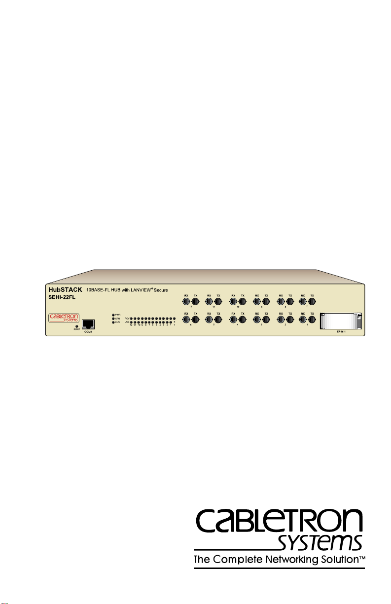
SEHI-22FL
INTELLIGENT STACKABLE HUB
USER’S GUIDE
Page 2

NOTICE
Cabletron Systems reserves the right to make changes in specifications and other information
contained in this document without prior notice. The reader should in all cases consult Cabletron
Systems to determine whether any such changes have been made.
The hardware, firmware, or software described in this manual is subject to change without notice.
IN NO EVENT SHALL CABLETRON SYSTEMS BE LIABLE FOR ANY INCIDENTAL,
INDIRECT, SPECIAL, OR CONSEQUENTIAL DAMAGES WHATSOEVER (INCLUDING BUT
NOT LIMITED TO LOST PROFITS) ARISING OUT OF OR RELATED TO THIS MANUAL OR
THE INFORMATION CONTAINED IN IT, EVEN IF CABLETRON SYSTEMS HAS BEEN
ADVISED OF, KNOWN, OR SHOULD HAVE KNOWN, THE POSSIBILITY OF SUCH
DAMAGES.
Copyright 1996 by Cabletron Systems, Inc., P.O. Box 5005, Rochester, NH 03866-5005
All Rights Reserved
Printed in the United States of America
Order Number: 9031652-01 April 1996
SPECTRUM, LANVIEW, MicroMMAC
Manager, EPIM, EPIM-A, EPIM-F1, EPIM-F2, EPIM-F3, EPIM-T, EPIM-X, FOT-F, FOT-F3
HubSTACK, SEH, SEHI
All other product names mentioned in this manual may be trademarks or registered trademarks of
their respective companies.
, and
TMS-3
Printed on Recycled Paper
, and
BRIM
are registered trademarks and
are trademarks of Cabletron Systems, Inc.
Element
,
SEHI User’s Guide i
Page 3

Notice
FCC NOTICE
This device complies with Part 15 of the FCC rules. Operation is subject to the following two
conditions: (1) this device may not cause harmful interference, and (2) this device must accept any
interference received, including interference that may cause undesired operation.
NOTE:
This equipment has been tested and found to comply with the limits for a Class A digital
device, pursuant to Part 15 of the FCC rules. These limits are designed to provide reasonable
protection against harmful interference when the equipment is operated in a commercial environment.
This equipment uses, generates, and can radiate radio frequency energy and if not installed in
accordance with the operator’s manual, may cause harmful interference to radio communications.
Operation of this equipment in a residential area is likely to cause interference in which case the user
will be required to correct the interference at his own expense.
WARNING:
party responsible for compliance could void the user’s authority to operate the equipment.
Changes or modifications made to this device which are not e xpressly appro v ed by the
DOC NOTICE
This digital apparatus does not exceed the Class A limits for radio noise emissions from digital
apparatus set out in the Radio Interference Regulations of the Canadian Department of
Communications.
Le présent appareil numérique n’émet pas de bruits radioélectriques dépassant les limites applicables
aux appareils numériques de la class A prescrites dans le Règlement sur le brouillage radioélectrique
édicté par le ministère des Communications du Canada.
VCCI NOTICE
This equipment is in the 1st Class Category (information equipment to be used in commercial and/or
industrial areas) and conforms to the standards set by the Voluntary Control Council for Interference
by Information T echnology Equipment (VCCI) aimed at preventing radio interference in commercial
and/or industrial areas.
Consequently, when used in a residential area or in an adjacent area thereto, radio interference may be
caused to radios and TV receivers, etc.
Read the instructions for correct handling.
ii SEHI User’s Guide
Page 4

Notice
CABLETRON SYSTEMS, INC. PROGRAM LICENSE AGREEMENT
IMPORTANT:
This document is an agreement between you, the end user, and Cabletron Systems, Inc. (“Cabletron”)
that sets forth your rights and obligations with respect to the Cabletron software program (the
“Program”) contained in this package. The Program may be contained in firmware, chips or other
media. BY UTILIZING THE ENCLOSED PRODUCT, YOU ARE AGREEING TO BECOME
BOUND BY THE TERMS OF THIS AGREEMENT, WHICH INCLUDES THE LICENSE AND
THE LIMITATION OF WARRANTY AND DISCLAIMER OF LIABILITY. IF YOU DO NOT
AGREE TO THE TERMS OF THIS AGREEMENT, PROMPTLY RETURN THE UNUSED
PRODUCT TO THE PLACE OF PURCHASE FOR A FULL REFUND.
Before utilizing this product, carefully read this License Agreement.
CABLETRON SOFTWARE PROGRAM LICENSE
1. LICENSE
package subject to the terms and conditions of this License Agreement.
You may not copy, reproduce or transmit any part of the Program except as permitted by the
Copyright Act of the United States or as authorized in writing by Cabletron.
2. OTHER RESTRICTIONS. You may not reverse engineer, decompile, or disassemble the
Program.
3. APPLICABLE LA W. This License Agreement shall be interpreted and governed under the laws
and in the state and federal courts of New Hampshire. You accept the personal jurisdiction and
venue of the New Hampshire courts.
. You have the right to use only the one (1) copy of the Program provided in this
EXCLUSION OF WARRANTY AND DISCLAIMER OF LIABILITY
1. EXCLUSION OF
writing, Cabletron makes no warranty, expressed or implied, concerning the Program (including
its documentation and media).
CABLETRON DISCLAIMS ALL WARRANTIES, OTHER THAN THOSE SUPPLIED TO
YOU BY CABLETRON IN WRITING, EITHER EXPRESSED OR IMPLIED, INCLUDING
BUT NOT LIMITED TO IMPLIED WARRANTIES OF MERCHANTABILITY AND
FITNESS FOR A PARTICULAR PURPOSE, WITH RESPECT TO THE PROGRAM, THE
ACCOMP ANYING WRITTEN MA TERIALS, AND ANY A CCOMP ANYING HARDWARE.
2. NO LIABILITY FOR CONSEQUENTIAL DAMAGES. IN NO EVENT SHALL
CABLETRON OR ITS SUPPLIERS BE LIABLE FOR ANY DAMAGES WHATSOEVER
(INCLUDING, WITHOUT LIMITATION, DAMAGES FOR LOSS OF BUSINESS,
PROFITS, BUSINESS INTERRUPTION, LOSS OF BUSINESS INFORMATION, SPECIAL,
INCIDENTAL, CONSEQUENTIAL, OR RELIANCE DAMAGES, OR OTHER LOSS)
ARISING OUT OF THE USE OR INABILITY TO USE THIS CABLETRON PRODUCT,
EVEN IF CABLETRON HAS BEEN ADVISED OF THE POSSIBILITY OF SUCH
DAMAGES. BECAUSE SOME STATES DO NOT ALLOW THE EXCLUSION OR
LIMITATION OF LIABILITY FOR CONSEQUENTIAL OR INCIDENTAL DAMAGES, OR
ON THE DURATION OR LIMITATION OF IMPLIED WARRANTIES, IN SOME
INSTANCES THE ABOVE LIMITATIONS AND EXCLUSIONS MAY NOT APPLY TO
YOU.
WARRANTY. Except as may be specifically provided by Cabletron in
SEHI User’s Guide iii
Page 5

Notice
UNITED STATES GOVERNMENT RESTRICTED RIGHTS
The enclosed product (a) was developed solely at private expense; (b) contains “restricted computer
software” submitted with restricted rights in accordance with Section 52227-19 (a) through (d) of the
Commercial Computer Software - Restricted Rights Clause and its successors, and (c) in all respects
is proprietary data belonging to Cabletron and/or its suppliers.
For Department of Defense units, the product is licensed with “Restricted Rights” as defined in the
DoD Supplement to the Federal Acquisition Regulations, Section 52.227-7013 (c) (1) (ii) and its
successors, and use, duplication, disclosure by the Government is subject to restrictions as set forth in
subparagraph (c) (1) (ii) of the Rights in Technical Data and Computer Software clause at
252.227-7013. Cabletron Systems, Inc., 35 Industrial Way, Rochester, New Hampshire 03867-0505.
iv SEHI User’s Guide
Page 6

CONTENTS
CHAPTER 1 INTRODUCTION
1.1 Using This Manual.......................................................................1-1
1.2 Document Conventions...............................................................1-2
1.3 Getting Help.................................................................................1-3
1.4 Related Manuals..........................................................................1-3
CHAPTER 2 SEHI FEATURES AND OPTIONS
2.1 SEHI Overview............................................................................2-2
2.2 SEHI Features............................................................................. 2-2
2.3 Stackable Capabilities.................................................................2-3
2.4 Remote Network Management Capabilities................................2-3
2.5 Optional Features........................................................................ 2-4
CHAPTER 3 INSTALLATION REQUIREMENTS AND
SPECIFICATIONS
3.1 Cable Specifications.................................................................... 3-1
3.1.1 HubSTACK Interconnect Cable Requirements............... 3-2
3.1.2 10BASE-FL Fiber Optic Network Requirements............. 3-2
3.1.3 10BASE-T UTP and STP Cable Specifications..............3-3
3.2 Network Port Specifications.........................................................3-4
3.3 COM Port Requirements.............................................................3-5
3.4 Transceiver Requirements ..........................................................3-5
3.5 Operating Specifications..............................................................3-6
3.6 Power Supply Requirements....................................................... 3-7
3.7 Environmental Requirements......................................................3-8
3.8 Agency Approvals........................................................................3-8
3.8.1 Safety.............................................................................. 3-8
3.8.2 Immunity ......................................................................... 3-8
3.8.3 Emission ......................................................................... 3-8
3.9 Physical Specifications................................................................ 3-8
SEHI User’s Guide v
Page 7

Contents
CHAPTER 4 INSTALLATION
4.1 Unpacking the SEHI.....................................................................4-1
4.2 Pre-installation Test .....................................................................4-2
4.3 Installing the SEHI .......................................................................4-2
4.3.1 Tabletop or Shelf Installation...........................................4-3
4.3.2 Rackmount Installation....................................................4-4
4.3.3 Stacking the SEHI...........................................................4-6
4.4 Connecting the SEHI to the Power Source..................................4-8
4.5 Adding/Replacing EPIMs .............................................................4-9
CHAPTER 5 CONNECTING TO THE NETWORK
5.1 Connecting the SEHI to the Network ...........................................5-1
5.1.1 Connecting Network Ports...............................................5-1
5.1.2 Connecting a UTP Segment to an EPIM-T .....................5-4
5.1.3 Connecting a Fiber Segment to an EPIM-F1/F2/F3........5-5
5.1.4 Connecting a Thin Coaxial Segment to an EPIM-C........5-8
5.1.5 Connecting an AUI Cable to an EPIM-A .........................5-9
5.1.6 Connecting an AUI Cable to an EPIM-X .......................5-11
5.2 FInishing the Installation ............................................................5-12
CHAPTER 6 TROUBLESHOOTING
6.1 Installation CheckOut...................................................................6-1
6.2 Using LANVIEW...........................................................................6-2
6.3 Using the RESET Button .............................................................6-4
6.4 Setting the NVRAM Switch ..........................................................6-5
CHAPTER 7 LOCAL MANAGEMENT
7.1 Local Management Keyboard Conventions.................................7-2
7.2 Management Terminal Setup.......................................................7-3
7.3 Accessing Local Management.....................................................7-6
7.4 The Feature Selection Screen .....................................................7-7
7.5 The Community Name Table Screen...........................................7-8
7.6 The Configuration Screen..........................................................7-10
7.7 The Trap Table Screen..............................................................7-14
7.8 The SNMP Tools Screen ...........................................................7-16
7.9 The Device Statistics Screen.....................................................7-20
vi SEHI User’s Guide
Page 8

Contents
APPENDIX A EPIM INFORMATION
A.1 EPIM Specifications.....................................................................A-1
A.1.1 EPIM-T............................................................................A-1
A.1.2 EPIM-F1 and EPIM-F2....................................................A-2
A.1.3 EPIM-F3..........................................................................A-3
A.1.4 EPIM-C............................................................................A-4
A.1.5 EPIM-A and EPIM-X (AUI Port) ......................................A-5
APPENDIX B IMAGE FILE DOWNLOAD USING OIDs
B.1 Setting up a UNIX Workstation as a TFTP Server ......................B-2
B.2 Standard TFTP Download...........................................................B-3
INDEX
SEHI User’s Guide vii
Page 9

CHAPTER 1
INTRODUCTION
Welcome to the Cabletron Systems
Hub User’s Guide
reference information for the SEHI-22FL.
NOTE
The term SEHI (Stackable Ethernet Hub with Intelligence) is
used throughout this manual when describing the features and
functions of the SEHI-22FL.
. This manual provides installation instructions and
SEHI-22FL Intelligent Stackable
1.1 USING THIS MANUAL
Read through this manual to gain an understanding of the features and
capabilities of the SEHI. A general knowledge of Ethernet and IEEE
802.3 type data communications networks and their physical layer
components is helpful when installing the SEHI.
Chapter 1,
document conventions, provides getting help information and concludes
with a list of related manuals.
Chapter 2,
and provides information about available options including EPIMs
(Ethernet Port Interface Modules) and HubSTACK interconnect cables.
Chapter 3,
installation requirements, network guidelines, and SEHI operating
specifications.
Introduction
SEHI Features and Options
Installation Requirements and Specifications
, outlines the contents of this manual, describes
, details the features of the SEHI
, describes
Chapter 4,
stackable or standalone hub.
Chapter 5,
SEHI to the network using the various media types.
Chapter 6,
to troubleshoot network problems.
SEHI User’s Guide 1-1
Installation
Connecting to the Network
Troubleshooting
, contains instructions for installing the SEHI as a
, explains how to connect the
, describes how to use the LANVIEW LEDs
Page 10

Chapter 1:
Introduction
Chapter 7,
Local Management
, describes how to use SEHI Local
Management screens and the available commands.
Appendix A,
EPIM Information
, provides specifications, cabling
information, and switch settings for the Ethernet Port Interface Modules.
Appendix B,
Image File Download Using OIDs
, provides instructions
for setting up a TFTP server and downloading image files to the SEHI by
setting specific MIB OID strings.
1.2 DOCUMENT CONVENTIONS
The following conventions are used throughout this document:
Note
NOTE
TIP
symbol. Calls the reader’s attention to any item of
information that may be of special importance.
Tip
symbol. Conveys helpful hints concerning procedures or
actions.
Caution
damage to the equipment.
!
CAUTION
Warning
equipment damage, personal injury or death.
1-2 SEHI User’s Guide
symbol. Contains information essential to avoid
symbol. Warns against an action that could result in
Page 11

Getting Help
1.3 GETTING HELP
If you need additional support related to this device, or if you have any
questions, comments, or suggestions concerning this manual, contact
Cabletron Systems Technical Support:
By phone (603) 332-9400
A.M
Monday – Friday; 8
By CompuServe GO CTRON from any ! prompt
By Internet mail [email protected]
By FTP ctron.com (134.141.197.25)
Login
Password
anonymous
your email address
Before calling Cabletron Systems Technical Support, have the following
information ready:
• A description of the failure
• A description of any action(s) already taken to resolve the problem
(e.g., changing mode switches, rebooting the unit, etc.)
• A description of your network environment (layout, cable type, etc.)
. – 8 P.M. Eastern Time
• Network load and frame size at the time of trouble (if known)
• The serial and revision numbers of all Cabletron Systems products in
the network
• The device history (i.e., have you returned the device before, is this a
recurring problem, etc.)
• Any previous Return Material Authorization (RMA) numbers
1.4 RELATED MANUALS
Use the Cabletron Systems
supplement the procedures and other technical data provided in this
manual. The procedures contained in the
User’s Guide
are referenced where appropriate, but not repeated in this
manual.
SEHI User’s Guide 1-3
SEH-22FL Stackable Hub User’s Guide
SEH-22FL Stackable Hub
to
Page 12
CHAPTER 2
SEHI FEATURES AND OPTIONS
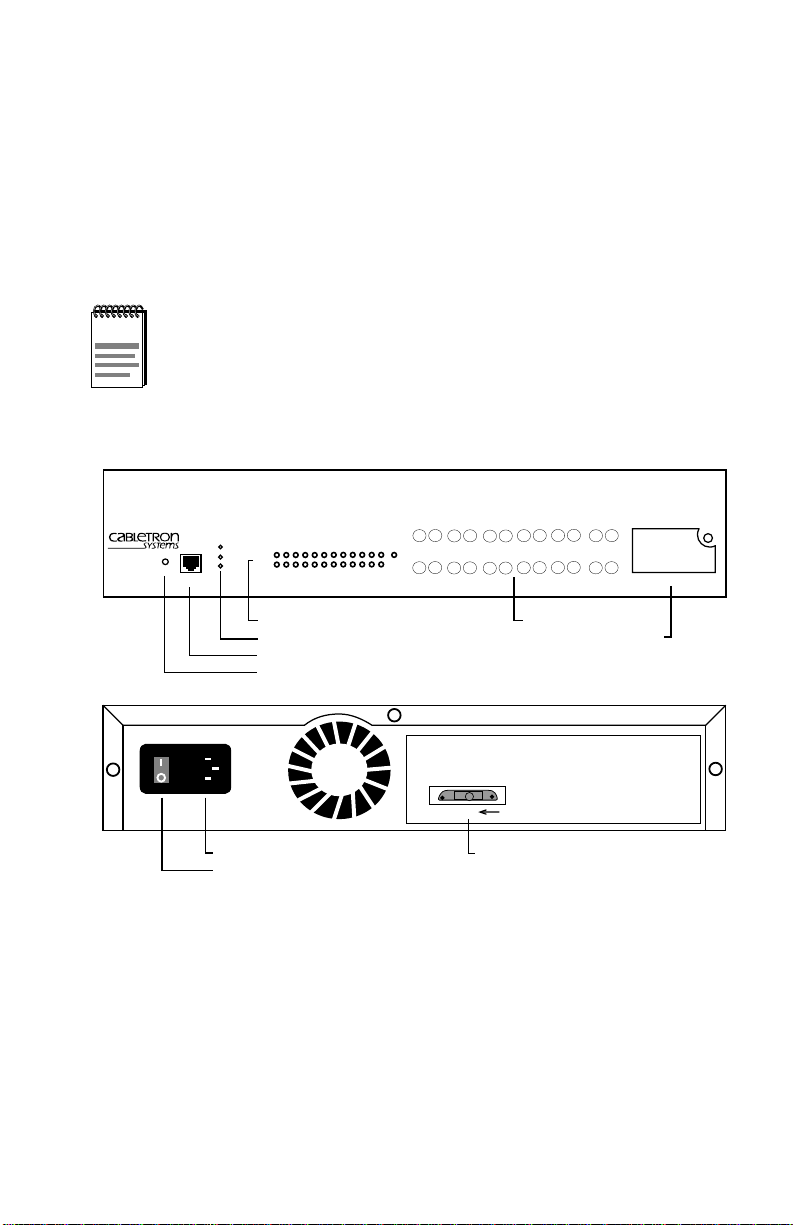
This chapter provides an overview of the SEHI-22FL and contains
sections detailing features and available options.
NOTE
HubSTACK
SEHI-22FL
The term SEHI (Stackable Ethernet Hub with Intelligence) is
used throughout this manual when describing features and
functions of the SEHI-22FL.
FRONT VIEW
10BASE-FL HUB WITH LANVIEW
PWR
CPU
RCV
LNK
COM
CLN
12 11 10 9 8 7 6 5 4 3 2 1
RESET
Port Status LEDs
System LEDs
COM Port
RESET Button
Power Supply
ON/OFF Switch
®
SECURE
REAR VIEW
RX
RX
TX
1112
RX
RX
TX
E
1
56
RX
TX
RX
TX
TX
10
9
RX
TX
RX
TX
TX
4
3
Network Ports 1-12
SEHI-22FL 100BASE-FL HUB WITH LANVIEW®
SEH INTERCONNECT
OUT
Interconnect Bus "OUT" Port
RX
RX
TX
TX
8
7
RX
RX
TX
TX
2
1
EPIM Slot
EPIM 1
165212
Figure 2-1 Front and Rear Views of the SEHI-22FL
SEHI User’s Guide 2-1
Page 13

Chapter 2:
SEHI Features and Options
2.1 SEHI OVERVIEW
The SEHI-22FL is an intelligent repeating hub providing front panel ports
for network connections and a rear panel HubSTACK Interconnect Bus
port for stackable connections. The SEHI is designed to manage the
Cabletron Systems SEH series of non-intelligent stackable hubs.
The SEHI-22FL provides twelve 10BASE-FL ST-type fiber optic ports
and one EPIM (Ethernet Port Interface Module) port.
2.2 SEHI FEATURES
This section provides detailed information about SEHI features and
capabilities.
Repeater Functionality
The SEHI fully conforms to the IEEE 802.3 10BASE-FL specifications,
and provides the flexibility to connect networks using IEEE 802.3,
Ethernet Version 1 or Version 2 equipment. The SEHI transmits retimed
data packets, regenerates the preamble, extends fragments, and arbitrates
collisions.
The SEHI automatically partitions problem segments, and reconnects
repaired segments to the network. This feature minimizes the impact on
network operation resulting from a problem on one segment by isolating
the problem segment. Only devices on the problem segment are affected.
When the problem is solved, the SEHI automatically reconnects the
isolated segment to the network.
FLASH EEPROMs
The SEHI uses FLASH EEPROMs that allow the downloading of new
and updated firmware using Cabletron Systems SPECTRUM Element
Manager/Windows or any device using BOOTP or TFTP protocols.
LANVIEW LEDs
Cabletron Systems LANVIEW Status Monitoring and Diagnostics
System is a troubleshooting tool that helps in diagnosing power failures,
collisions, cable faults, and link problems. The LANVIEW LEDs are
conveniently located on the SEHI front panel.
2-2 SEHI User’s Guide
Page 14

Stackable Capabilities
RESET Button
Resetting the hub with the front panel RESET button reboots the SEHI
and initializes the processor.
Local Management
Manage the SEHI and attached segments through Local Management on
the SEHI. Local Management provides full packet and error statistics for
the entire stack, individual device, or individual port. Access Local
Management by attaching a DEC VT320 terminal or a PC using VT320
emulation software to the SEHI RJ45 COM port.
2.3 STACKABLE CAPABILITIES
The SEHI intelligent hub is designed to manage the Cabletron Systems
series of SEH non-intelligent hubs. The SEHI serves as the logical “top”
of the stack. It manages all SEH hubs in the stack providing full packet
and error statistics for the entire stack, individual device, or individual
port.
Stack up to four SEH non-intelligent hubs with one SEHI using Cabletron
Systems external HubSTACK Interconnect cables. Stackable
configurations make it possible to maintain only one IEEE repeater hop
while providing up to 130 10BASE-T Ethernet ports. Add or remove hubs
from the stack without powering down.
2.4 REMOTE NETWORK MANAGEMENT
CAPABILITIES
Manage the SEHI remotely with any SNMP network management
system. Cabletron Systems offers the following remote management
packages:
• Cabletron Systems SPECTRUM
• Cabletron Systems SPECTRUM Element Manager/Windows
• Cabletron Systems Remote SPECTRUM Portable Management
Applications
• Third Party SNMP compliant Network Management Packages
SEHI User’s Guide 2-3
Page 15

Chapter 2:
SEHI Features and Options
2.5 OPTIONAL FEATURES
The following features are not included with the SEHI, but are purchased
separately from Cabletron Systems.
Ethernet Port Interface Modules (EPIMs)
EPIMs enable the expansion of the network through a variety of media.
Cabletron Systems offers the EPIMs shown in Table 2-1.
Table 2-1 EPIMs
EPIM Media Type Connector
EPIM-A AUI DB15 (Female)
EPIM-C 10BASE2 Thin Coaxial BNC
EPIM-T
EPIM-X Standard T r ansceiver DB15 (Male)
EPIM-F1 Multimode Fiber SMA
EPIM-F2 Multimode Fiber ST
EPIM-F3 Single Mode Fiber ST
10BASE-T Unshielded Twisted
Pair
RJ45
HubSTACK Interconnect Cables
Stack hubs together with Cabletron Systems HubSTACK Interconnect
cables. Table 2-2 lists the part number and the application for each cable.
Table 2-2 HubSTACK Interconnect Cables
P/N Description Application
9380110
9380111
12" HubSTACK
Interconnect Cable
18" HubSTACK
Interconnect Cable
SEH to SEH connections.
SEHI to SEH connections.
Rack Mount Hardware
The SEHI can be installed in a 19-inch rack. Cabletron offers an
accessory package that includes brackets and mounting screws. The part
number for the accessory package is SEHI-ACCY-KIT.
2-4 SEHI User’s Guide
Page 16

CHAPTER 3
INSTALLATION REQUIREMENTS AND
SPECIFICATIONS
This chapter describes cabling requirements, network guidelines, and
operating specifications for the SEHI.
The network must meet the requirements and conditions
specified in this chapter to obtain satisfactory performance from
!
CAUTION
The network must meet the requirements and conditions specified in this
chapter to obtain satisfactory performance from this equipment. Failure to
follow these guidelines can result in poor network performance.
3.1 CABLE SPECIFICATIONS
The SEHI-22FL network ports support 10BASE-FL Multimode Fiber
Optic cabling.
this equipment. Failure to follow these guidelines can result in
poor network performance.
Ethernet Port Interface Modules (EPIMs) expand a network using
Unshielded Twisted Pair (UTP), Shielded Twisted Pair (STP), Multimode
Fiber Optic, Single Mode Fiber Optic, or Thin Coaxial cabling. For
information concerning EPIMs, refer to Appendix A.
The rear panel Interconnect Bus port supports Cabletron Systems
HubSTACK Interconnect cables for stackable applications.
T ak e care in planning and preparing the network cabling and connections.
The quality of the connections and the length of cables are critical factors
in determining the reliability of the network. The following sections
provide the specifications for each media type.
SEHI User’s Guide 3-1
Page 17

Chapter 3: Installation Requirements and Specifications
3.1.1 HubSTACK Interconnect Cable Requirements
Attach the SEHI to modules in the stack with the SEHI HubSTACK
Interconnect cable available only from Cabletron Systems. Refer to
Chapter 1 for cable part numbers. The cable attaches to the SEHI rear
panel bus port.
The rear panel of the SEHI has an Interconnect Bus Out port (male
connector) to stack SEH non-intelligent hubs together. Stack up to four
SEH hubs together with one SEHI.
3.1.2 10BASE-FL Fiber Optic Network Requirements
Table 3-1 shows Multimode Fiber Optic Cable specifications for the
SEHI-22FL.
Table 3-1 Multimode Fiber Optic Cable Specifications
Cable Type Attenuation Maximum Cable Length
50/125 µm 13.0 dB or less Maximum fiber optic cable length is 2
62.5/125 µm 16.0 dB or less
100/140 µm 19.0 dB or less
km (2187.2 yds). However, IEEE 802.3
specifications allow for a maximum of 1
km (1093.6 yds).
Attenuation
T est the fiber optic cable with a fiber optic attenuation test set adjusted for
an 850 nm wavelength. This test verifies that the signal loss in a cable is
within an acceptable level. Table 3-1 shows the attenuation for each
Multimode cable type.
Fiber Optic Budget and Propagation Delay
Determine the maximum fiber optic cable length by calculating the fiber
optic budget delay and total network propagation before the fiber optic
cable runs are incorporated into a network design.
Fiber optic budget is the combination of the optical loss due to the fiber
optic cable, in-line splices, and fiber optic connectors.
Propagation delay is the amount of time it takes data to travel from the
sending device to the receiving device. Total propagation delay allowed
for the network is 25.6 µs (51.2 µs roundtrip). If the total propagation
delay between any two nodes on the network exceeds 25.6 µs, then use
bridges.
3-2 SEHI User’s Guide
Page 18

Cable Specifications
3.1.3 10BASE-T UTP and STP Cable Specifications
The devices and 10BASE-T Twisted Pair Segments connected to an SEHI
EPIM-T module must meet the IEEE 802.3 10BASE-T specifications
shown below:
Length
The IEEE 802.3 10BASE-T standard requires that 10BASE-T devices
transmit over a 100 meter (328 foot) link using 22-24 AWG Unshielded
Twisted Pair (UTP) wire. However, cable quality largely determines the
maximum link length. With high quality, low attenuation cable, link
lengths of up to 200 meters are achievable. Cable delay limits the
maximum link length to 200 meters, regardless of the cable type.
Insertion Loss
The maximum insertion loss allowed for a 10BASE-T link is 11.5 dB at
all frequencies between 5.0 and 10 MHz. This includes the attenuation of
the cables, connectors, patch panels, and reflection losses due to
impedance mismatches in the link segment.
Impedance
Cabletron Systems 10BASE-T Twisted Pair products work on twisted pair
cable with 75 to 165 ohms impedance. UTP cables typically have an
impedance of 85 to 110 ohms.
Shielded Twisted Pair (STP) cables, such as IBM Type 1 cable, are also
used. The impedance of IBM Type 1 cable is typically 150 ohms. Higher
impedance increases signal reflection, but because the cable is shielded,
signal reflection has little effect on the quality of the received signal due
to the lack of crosstalk between the shielded cable pairs.
Jitter
Intersymbol interference and reflections cause jitter in the bit cell timing,
resulting in data errors. A 10BASE-T link must not generate more than
5.0 ns of jitter. If the cable meets the impedance requirements for a
10BASE-T link, jitter should not be a concern.
Delay
The maximum propagation delay of a 10BASE-T link segment must not
exceed 1000 ns. This 1000 ns maximum delay limits the maximum link
segment length to no greater than 200 meters.
SEHI User’s Guide 3-3
Page 19

Chapter 3: Installation Requirements and Specifications
Crosstalk
Crosstalk is caused by signal coupling between the different cable pairs
contained within a multi-pair cable bundle. 10BASE-T transceivers are
designed so that the user does not need to be concerned about cable
crosstalk, provided the cable meets all other requirements.
Noise
Noise is caused by either crosstalk or externally induced impulses.
Impulse noise may cause data errors if the impulses occur at very specific
times during data transmission. Generally , the user need not be concerned
about noise. If noise-related data errors are suspected, it may be necessary
to either reroute the cable or eliminate the source of the impulse noise.
Temperature
Multi-pair PVC 24 AWG cables typically have an attenuation of
8 dB to 10 dB/100 meters at 20°C (68°F). The attenuation of PVC
insulated cable varies significantly with temperature. At temperatures
greater than 40°C (104°F), Cabletron Systems recommends the use of
plenum-rated cables to ensure that cable attenuation remains within
specification.
3.2 NETWORK PORT SPECIFICATIONS
The SEHI-22FL provides ST-type ports for 10BASE-FL Multimode Fiber
Optic cabling. Figure 3-1 shows the network ports.
RX
RX
RX
TX
TX
1112
RX
RX
TX
TX
56
Figure 3-1 SEHI-22FL Network Ports
3-4 SEHI User’s Guide
RX
RX
RX
TX
TX
10
9
RX
TX
TX
4
3
RX
TX
TX
8
7
RX
RX
TX
TX
2
1
09162_04
Page 20

COM Port Requirements
3.3 COM PORT REQUIREMENTS
The RJ45 COM port supports access to a Local Management Console.
The Console port supports a Digital Equipment Corporation, VT320
terminal or PC emulation of the VT320 terminal. Figure 3-2 shows the
pinouts for the RJ45 COM port.
1 2 3 4 5 6 7 8
COM
1. Transmit Data
2. Data Carrier Detect
3. Data Set Ready
4. Receive Data
Figure 3-2 COM Port Pinouts
5. Signal Ground
6. Data Terminal Ready
7. Request To Send
8. Clear To Send
165201
3.4 TRANSCEIVER REQUIREMENTS
When connecting an external network segment through a transceiver to
the SEHI with an EPIM-A, the following requirements must be met:
• The transceiver or Ethernet device to which the module is connected
must meet IEEE 802.3 standards, and/or Ethernet Version 1.0 or
Version 2.0 standards.
• The Signal Quality Error (SQE) test function on the transceiver must
be disabled when it is connected to a repeater or to an Ethernet Version
1.0 device. In addition, some Version 2.0 equipment does not support
the SQE test. Devices that do not support the SQE test interpret the
SQE test pulse as a collision.
SEHI User’s Guide 3-5
Page 21

Chapter 3: Installation Requirements and Specifications
3.5 OPERATING SPECIFICATIONS
The operating specifications for the SEHI are described in this section.
Cabletron Systems reserves the right to change these specifications at any
time without notice.
System Specifications
Operating System Memory: 1.5 MB
Internal Processor: Intel i960 operating at 16 MHz
Ethernet Controller: National Semiconductor DP83916
Non-Volatile RAM: 32 KB with battery back-up
EPROM: 64 KB
FLASH MEMORY: 1 MB
Delay Time (Start of Packets) Specifications
Twisted Pair to EPIM-A: 1.10 ms
Twisted Pair to Twisted Pair: 1.00 ms
EPIM-A to Twisted Pair: 1.00 ms
Delay Times (JAM) Specifications
Twisted Pair to EPIM-A: 960 ns
Preamble Specifications
Input: Minimum of 40 bits required
Output: 64 bits min. (last 2 bits are 1,1)
3-6 SEHI User’s Guide
Page 22

Power Supply Requirements
JAM Output Specifications
Collisions are propagated through the network using the J AM signal of an
alternating pattern of 1’s and 0’s in accordance with 802.3 specifications
for a repeater unit.
Fragment Extension Specifications
Fragments are extended to a minimum of 96 bits using the JAM [1,0].
Fault Protection Specifications
Each segment disconnects itself from the other segments if 32 consecutiv e
collisions occur, or if the collision detector of a segment is on for longer
than approximately 110 µs. This fault protection resets automatically after
one packet is transmitted/received onto the fault protected segment
without causing a collision.
3.6 POWER SUPPLY REQUIREMENTS
The SEHI has a universal power supply. The input power requirements
are listed in Table 3-2.
Table 3-2 Power Requirements
Model Voltage Range Frequency Range
SEHI-22FL
100–125 Vac
or 200–250 Vac
50/60 Hz
The power supply has two outputs of +5 Vdc and +12 Vdc. The maximum
output power is 40 W and the minimum efficiency is 65% under all
conditions of the line at full load. The minimum and maximum load
currents from each output are listed in Table 3-3.
Table 3-3 Power Supply Output Specifications
Output Min. Load Max. Load Max Power
+5 Vdc 0.75 A 4 A 20 W
+12 Vdc 0.00 A 2 A 24 W
SEHI User’s Guide 3-7
Page 23

Chapter 3: Installation Requirements and Specifications
3.7 ENVIRONMENTAL REQUIREMENTS
The environmental requirements for the SEHI are detailed in this section.
Operating T emperature: 5°C to 40°C (41°F to 104°F)
Storage T emperature: -30°C to 90°C (-22°F to 194°F)
Operating Humidity: 5% to 95% (non-condensing)
3.8 AGENCY APPROVALS
The Safety, Immunity, and Emission approvals for the SEHI are detailed
in this section.
3.8.1 Safety
This unit meets the safety requirements of UL 1950, CSA C22.2 No. 950,
IEC 950, and EN 60950.
3.8.2 Immunity
This unit meets the immunity requirements of EN 50082-1 including
IEC 801-2 (ESD), IEC 801-3 (Radiated Susceptibility),
and IEC 801-4 (EFT/B).
3.8.3 Emission
This unit meets the emission requirements of FCC Part 15 Class A,
EN 55022 Class A, and VCCI Class I.
3.9 PHYSICAL SPECIFICATIONS
This section details the physical specifications for the SEHI.
Dimensions (H x W x D): (7.2 cm x 43.6 cm x 34.6 cm)
(2.8 in x 17.0 in x 13.5 in)
Weight (Unit): 3 kg (6.5 lb)
3-8 SEHI User’s Guide
Page 24

CHAPTER 4
INSTALLATION
This chapter outlines the procedure for attaching the SEHI to the network
as a stackable or standalone device. Ensure that the network meets the
guidelines and requirements outlined in Chapter 3, Installation
Requirements and Specifications, before installing the SEHI.
Failure to follow installation instructions may result in an
electrical shock hazard.
4.1 UNPACKING THE SEHI
Unpack the SEHI as follows:
1. Remove the shipping material covering the SEHI in the shipping box.
2. Carefully remove the SEHI from the shipping box and set it aside to
prevent damage.
3. Visually inspect the SEHI. If there are any signs of damage, contact
Cabletron Systems Technical Support immediately.
4. Read the SEHI Release Notes included in the shipping box.
NOTE
SEHI User’s Guide 4-1
Cabletron Systems includes a 3-1/2" disk with the SEHI that
contains a backup copy of the SEHI Flash Firmware Image
File. Download the file to the SEHI if the existing image
becomes corrupted.
Page 25
Chapter 4: Installation
4.2 PRE-INSTALLATION TEST
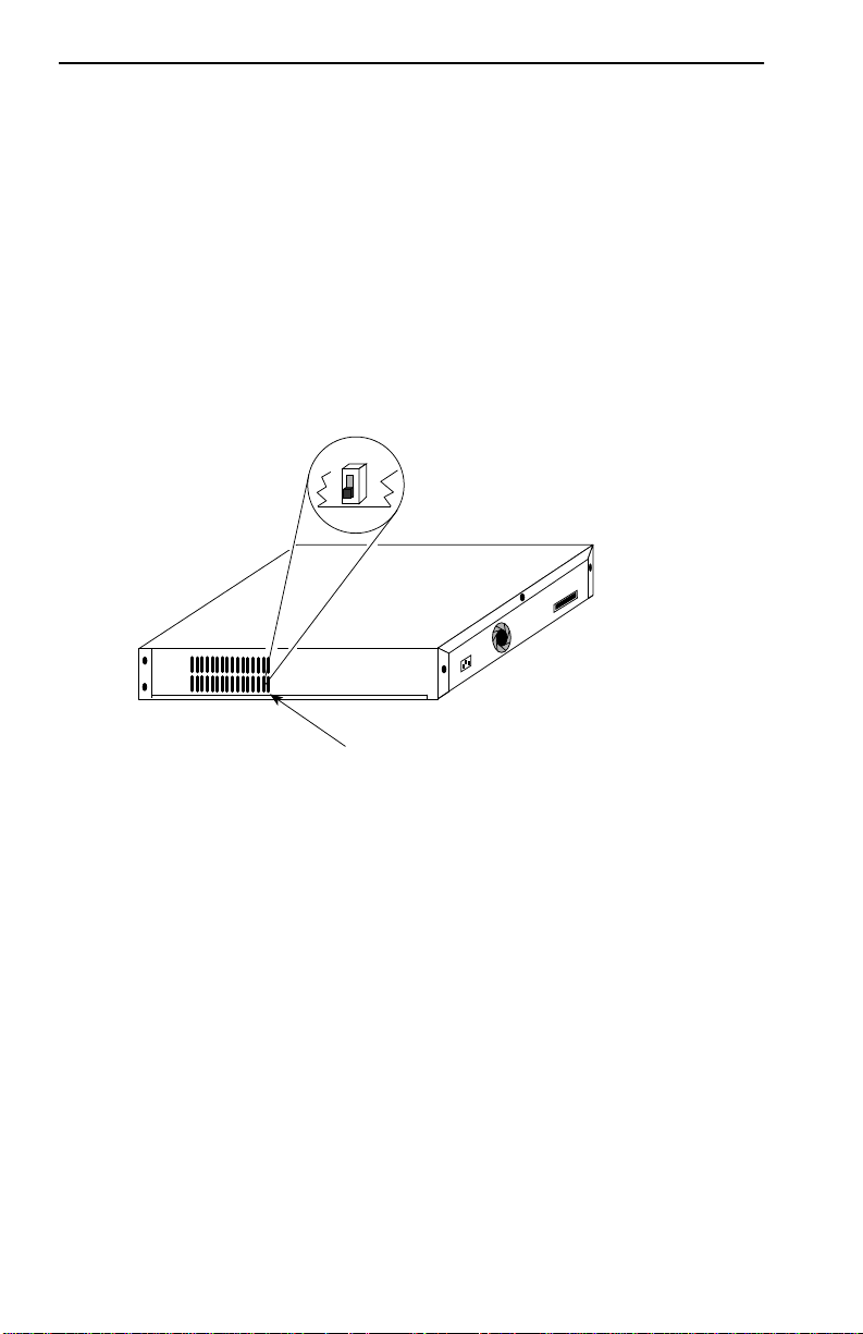
The SEHI is equipped with an NVRAM reset switch (Figure 4-1) located
behind the grillwork on the side of the hub. Ensure that this switch is in
the DOWN position by looking in through the grillwork on the right side
of the hub. If the switch is UP, move it into the DOWN position with a
non-metallic tool. Do not remove the chassis cover to perform this
operation. Leaving the switch in the UP position results in user-installed
parameters such as IP address and Community Names being cleared from
NVRAM whenever the SEHI loses power and/or is reset. See Chapter 6,
Section 6.4, for detailed instructions on setting the NVRAM switch.
Rear of Chassis
NVRAM Switch located behind grating
09162_05
Figure 4-1 NVRAM Switch Location
4.3 INSTALLING THE SEHI
The SEHI may be installed on a tabletop or shelf, or in a 19-inch rack, and
configured as a standalone or stacked hub.
Refer to Section 4.3.1 for information concerning a tabletop or shelf
installation. Section 4.3.2 describes the rackmount installation.
4-2 SEHI User’s Guide
Page 26
Installing the SEHI
4.3.1 Tabletop or Shelf Installation
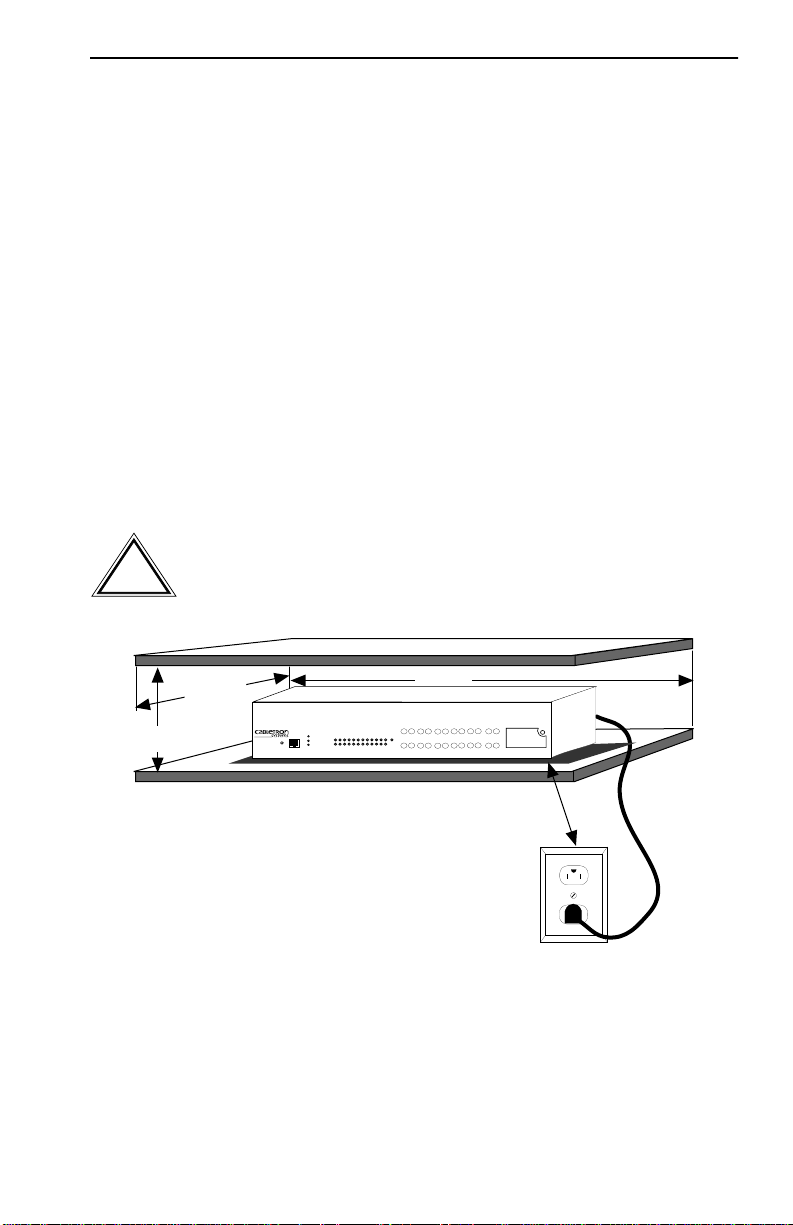
This section provides guidelines for installation on a tabletop or shelf.
Tabletop and shelf installations must be within reach of the network
cabling and meet the requirements listed below:
• A single phase grounded power receptacle that meets the power supply
requirements listed in Chapter 3 under Power Supply Requirements
must be located within seven feet of the location.
• In a shelf installation, the shelf must be able to support 30 pounds of
static weight for each device in the stack.
• Maintain a temperature of between 5°C (41°F) and 40°C (104°F) at
the site with fluctuations of less than 10°C (18°F) per hour.
For a tabletop or shelf installation, locate the SEHI within seven feet of its
power source and with an unrestricted free surface area as shown in
Figure 4-2.
In order to allow for proper cooling, there must be a two-inch
clearance on either side and the back of the unit.
!
CAUTION
21 IN.
®
SECURE
RX
RX
E
1
RX
RX
RX
TX
RX
TX
TX
TX
RX
TX
TX
1112
10
789
RX
RX
RX
TX
RX
TX
TX
TX
RX
TX
TX
56
4
EPIM 1
123
6 IN.
18 IN.
HubSTACK
SEHI-22FL
RESET
10BASE-FL HUB
PWR
CPU
CLN
COM
WITH
LANVIEW
RCV
LNK
12 11 10 9 8 7 6 5 4 3 2 1
7 FT
0165203
Figure 4-2 Tabletop or Shelf Installation
If the installation requires that the SEHI is to be stacked, proceed to
Section 4.3.3. Otherwise, continue by connecting power as described in
Section 4.4.
SEHI User’s Guide 4-3
Page 27
Chapter 4: Installation
4.3.2 Rackmount Installation
To install the SEHI in a 19-inch rack, Cabletron Systems offers an
accessory kit that includes rackmount brackets, mounting screws, and a
strain-relief bracket for cable management. The accessory kit is not
included with the SEHI, but can be purchased separately from Cabletron
Systems using the part number SEHI-ACCY-KIT.
Rack mounting the SEHI involves the following:
• Attaching the strain-relief bracket
• Rack mounting the SEHI
• Stacking the SEHI when applicable
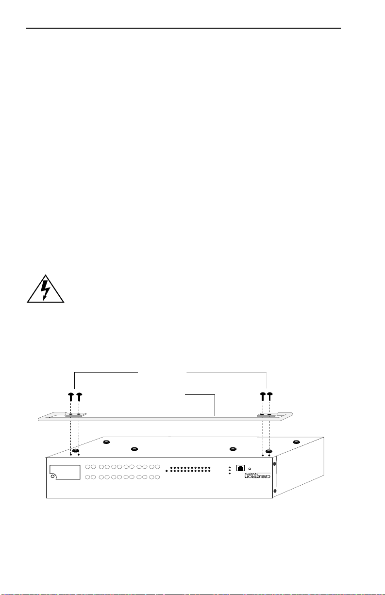
Attaching the Strain-Relief Bracket
Attach the strain-relief bracket to the front of the SEHI as follows:
1. Locate the strain-relief bracket and four 8-32 x 3/8 inch screws from
the SEHI-ACCY-KIT package.
Do NOT attempt to attach the strain-relief with screws other
than the 8-32 x 3/8-inch screws included with the SEHI
accessory kit. Use of longer screws may damage the unit or
cause electrical shock.
2. Attach the strain-relief bracket to the bottom of the SEHI (Figure 4-3).
Screws (4)
Strain-Relief Bracket
1
3
EPIM 1
2
4
56
1
TX
RX
1112
TX
RX
E
TX
RX
TX
RX
SECURE
®
TX
TX
TX
RX
7
TX
TX
RX
RX
TX
RX
RX
9
8
10
TX
RX
TX
RX
RX
WITH
LANVIEW
12 11 10 9 8 7 6 5 4 3 2 1
Figure 4-3 Attaching the Strain-Relief Bracket
4-4 SEHI User’s Guide
COM
RESET
CLN
LNK
RCV
CPU
PWR
SEHI-22FL
HubSTACK
10BASE-FL HUB
0165204
Page 28
Installing the SEHI
Rack Mounting the SEHI
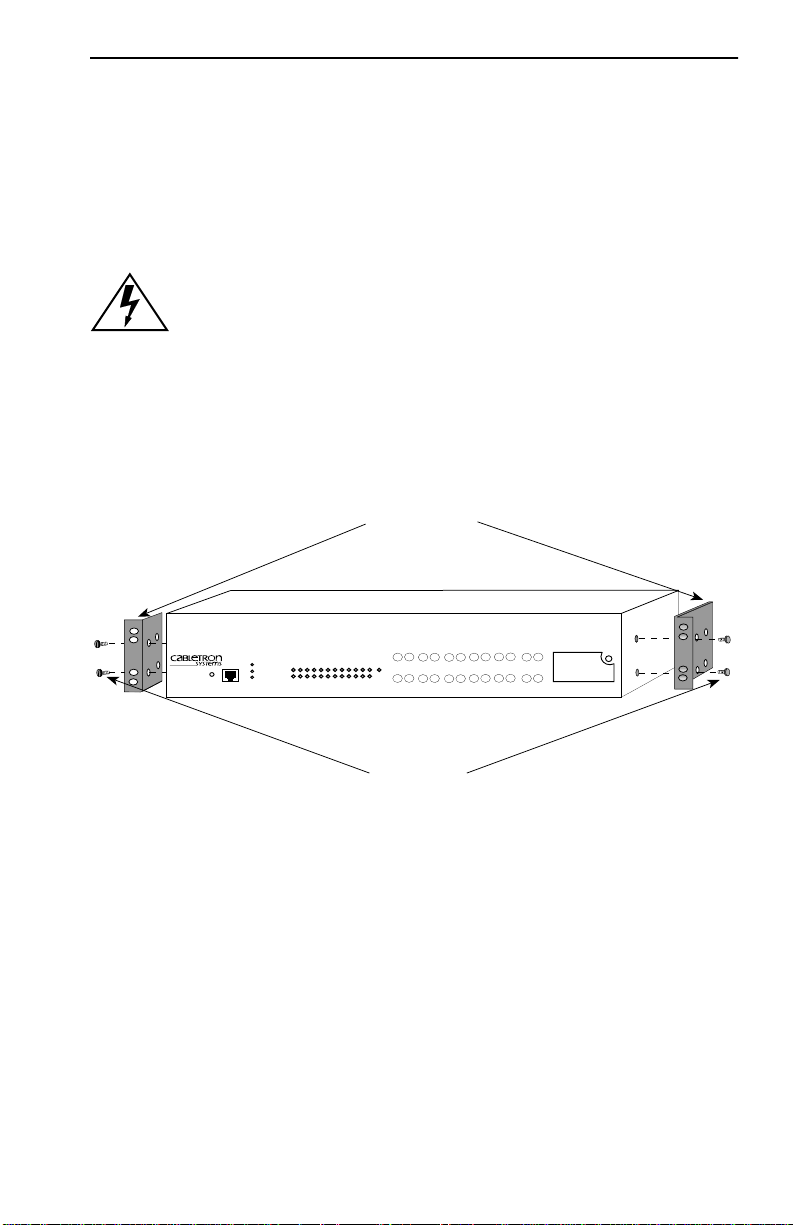
Refer to Figure 4-4 and proceed as follows to install the SEHI into a
19-inch rack.
1. Remove four cover screws (two from each side) located along the
front edges of each side of the SEHI.
Do not remove the cover from the SEHI. Do not remove any
other screws from the unit.
2. Using the four 6-32 x 3/8-inch replacement flathead cover screws
provided in the SEHI-ACCY-KIT, attach the rack mounting brackets
to each side of the SEHI.
Rack Mounting
Brackets (2)
HubSTACK
SEHI-22FL
RESET
10BASE-FL HUB
PWR
CPU
CLN
COM
RCV
LNK
12 11 10 9 8 7 6 5 4 3 2 1
WITH
LANVIEW
®
SECURE
RX
RX
E
1
Screws (4)
RX
RX
RX
RX
TX
RX
TX
1112
RX
TX
RX
TX
56
TX
TX
TX
10
RX
TX
4
TX
8
7
9
RX
RX
TX
TX
TX
2
3
EPIM 1
1
0165205
Figure 4-4 Installing the Rack Mounting Brackets
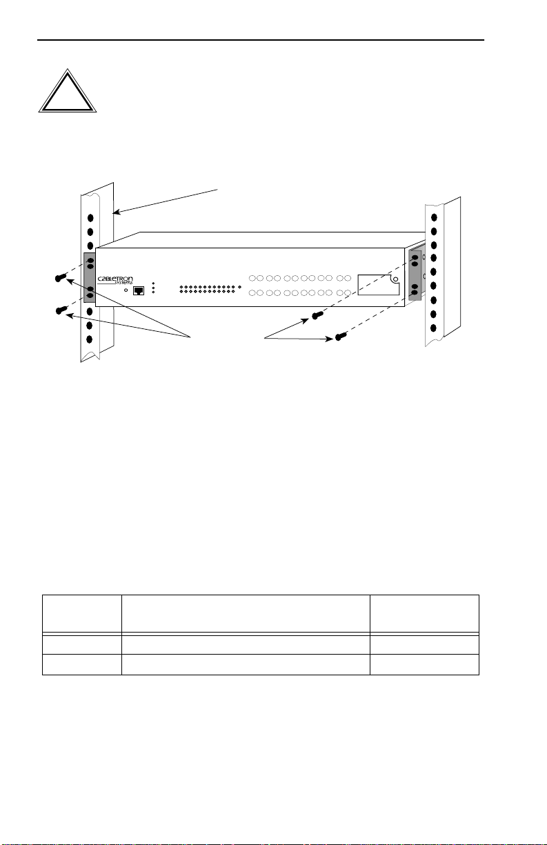
3. Ensure that the rack used will support the unit and that the rack will
remain stable with the unit installed in it. Support the SEH securely
from underneath and align the brackets of the SEH chassis with the
screw holes in the equipment rack as shown in Figure 4-5. Fasten the
SEH to the equipment rack securely.
SEHI User’s Guide 4-5
Page 29
Chapter 4: Installation
The cooling fans at the rear panel of the SEHI must have
adequate clearance (two inches on either side and in the rear)
!
CAUTION
for unrestricted air flow. The temperature for the selected
location must be maintained between 5°C and 40°C, and
fluctuate less than 10°C per hour.
19-Inch Rack
HubSTACK
SEHI-22FL
RESET
10BASE-FL HUB
PWR
CPU
CLN
COM
RCV
LNK
12 11 10 9 8 7 6 5 4 3 2 1
WITH
LANVIEW
®
SECURE
RX
RX
TX
TX
1112
RX
RX
TX
TX
E
1
56
RX
RX
RX
TX
TX
RX
TX
10
RX
RX
TX
4
TX
8
7
9
RX
RX
TX
TX
TX
2
3
EPIM 1
1
Screws (4)
0165206
Figure 4-5 Installing the SEHI in the Rack
If the installation requires stacking the SEHI, proceed to Section 4.3.3.
Otherwise, continue by connecting power as described in Section 4.4.
4.3.3 Stacking the SEHI
The rear panel of the SEHI has an Interconnect Bus Out Port (male
connector). Daisy chain units together using Cabletron Systems
HubSTACK Interconnect cables. Table 4-1 describes each cable.
Table 4-1 HubSTACK Interconnect Cables
Part
Number
9380110 12" HubSTACK Interconnect Cable SEH to SEH
9380111 18" HubSTACK Interconnect Cable SEHI to SEH
Description Application
4-6 SEHI User’s Guide
Page 30
Installing the SEHI
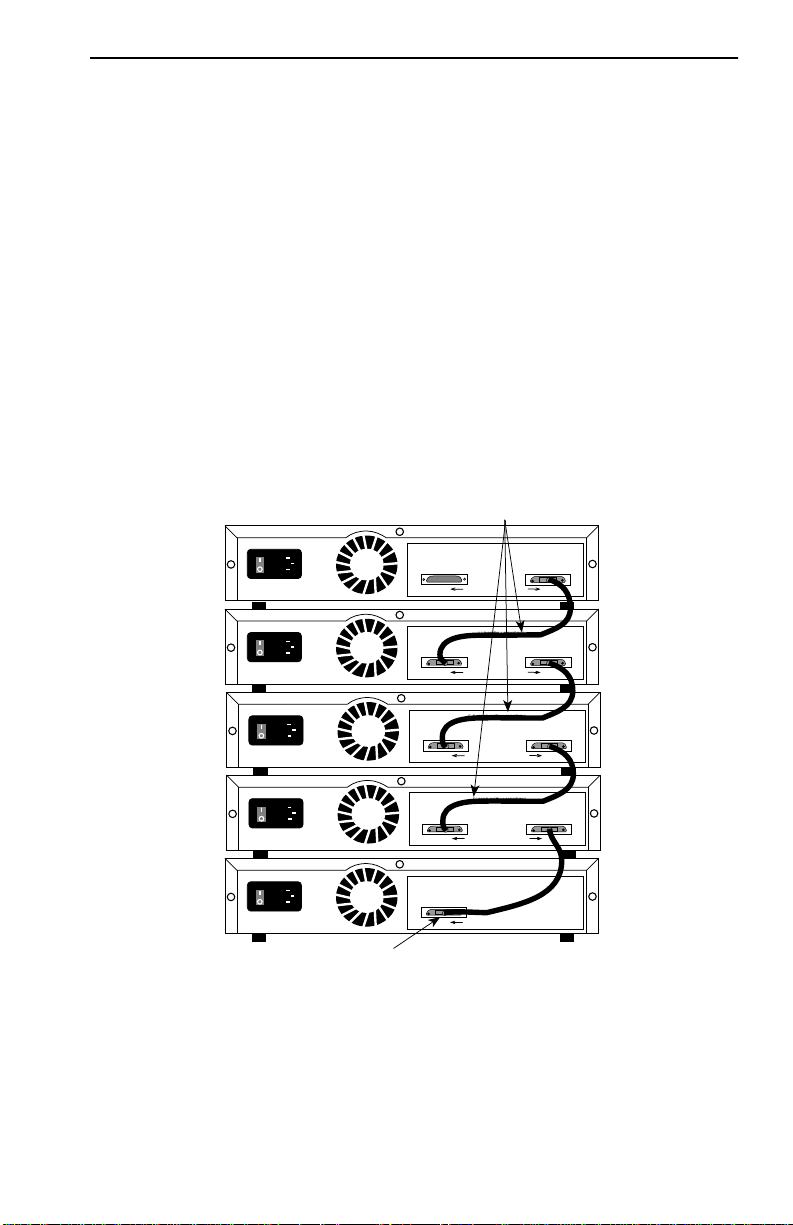
To stack the SEHI together with an SEH non-intelligent hub, proceed as
follows:
1. Attach the SEHI HubSTACK Interconnect cable to the “OUT” port on
the rear panel of the SEHI as shown in Figure 4-6.
2. Attach the other end of the SEHI HubSTACK Interconnect cable to
the “IN” port on the rear panel of the SEH.
To stack SEH non-intelligent hubs together, proceed as follows:
1. Attach the SEH HubSTACK Interconnect cable to the “OUT” port on
the rear panel of the SEH as shown in Figure 4-6.
2. Attach the other end of the SEH HubSTACK Interconnect cable to the
“IN” port on the rear panel of the SEH next in the stack.
SEH HubSTACK
Interconnect Cables
SEH-22FL 100BASE-FL HUB WITH LANVIEW®
SEH INTERCONNECT
OUT
IN
SEH-22FL 100BASE-FL HUB WITH LANVIEW®
SEH INTERCONNECT
SEHI HubSTACK
Interconnect Cable
OUT
SEH-22FL 100BASE-FL HUB WITH LANVIEW®
SEH INTERCONNECT
OUT
SEH-22FL 100BASE-FL HUB WITH LANVIEW®
SEH INTERCONNECT
OUT
SEHI-22FL 100BASE-FL HUB WITH LANVIEW®
SEH INTERCONNECT
OUT
IN
IN
IN
165210
Figure 4-6 Stacking the SEHI
SEHI User’s Guide 4-7
Page 31
Chapter 4: Installation
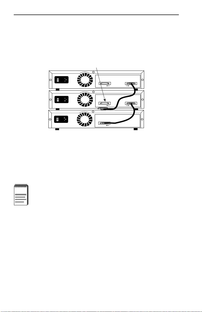
If one end of a HubSTACK Interconnect cable is disconnected without
disconnecting the other end attached to the hub, disconnect the cable from
the OUT port as shown in Figure 4-7 to ensure that the HubSTACK
Interconnect cable is terminated properly.
Disconnect SEH and SEHI
Interconnect Cables at the "OUT" Port
SEH-22FL
100BASE-FL HUB WITH LANVIEW®
SEH INTERCONNECT
SEH-22FL
SEHI-22FL
OUT
100BASE-FL HUB WITH LANVIEW®
SEH INTERCONNECT
OUT
100BASE-FL HUB WITH LANVIEW®
SEH INTERCONNECT
OUT
IN
IN
165211
Figure 4-7 Disconnecting the HubSTACK Interconnect Cable
Proceed to Section 4.4 to connect power.
4.4 CONNECTING THE SEHI TO THE POWER SOURCE
NOTE
Connect the SEHI to the power source as follows:
1. Plug the power cord into the back panel of the SEHI.
2. Plug the other end of the power cord into a grounded wall outlet.
3. Verify that the PWR LED is on, indicating that the SEHI is receiving
4-8 SEHI User’s Guide
The SEHI uses a universal power supply that operates
between 100–125 Vac or 200–250 Vac, 50/60 Hz.
power. After the SEHI runs a self test, the CPU LED blinks green
indicating normal operation. If the LED remains red, the processor is
faulty, contact Cabletron Systems Technical Support.
Page 32
Adding/Replacing EPIMs
4.5 ADDING/REPLACING EPIMS
This section contains procedures on how to add or replace an Ethernet
Port Interface Module (EPIM) to upgrade or change the capabilities of
your SEHI. After installing a new EPIM, refer to the appropriate EPIM
section in Appendix A to verify proper operation.
Observe all static precautions while handling EPIMs.
!
CAUTION
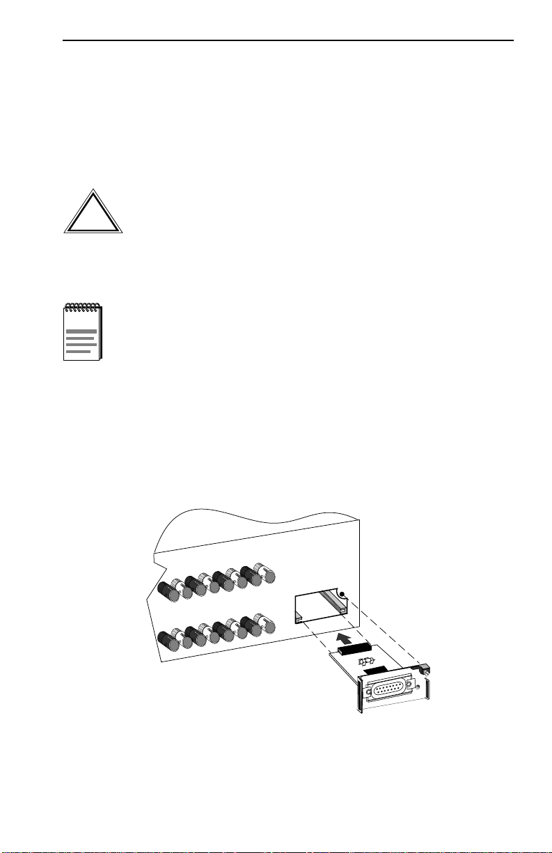
Perform the following steps to install an EPIM:
NOTE
prevent damage to the connector.
1. Remove the coverplate or the EPIM (whichever applies).
2. Slide the new EPIM into place, making sure that the connectors on the
rear of the EPIM align correctly and firmly with the connector inside
the SEHI. See Figure 4-8.
3. Tighten the mounting screw.
TX
RX
TX
RX
TX
RX
TX
7
8
9
When removing an EPIM, pull the module out straight to
10
TX
RX
TX
RX
3
4
165202
TX
RX
TX
RX
1
2
EPIM-1
PWR
EPIM-A
Figure 4-8 Installing an EPIM
SEHI User’s Guide 4-9
Page 33

CHAPTER 5
CONNECTING TO THE NETWORK
This chapter outlines the procedure for connecting the SEHI to a network.
Ensure that the network meets the guidelines and requirements outlined in
Chapter 3, Installation Requirements and Specifications, before
installing the SEHI.
5.1 CONNECTING THE SEHI TO THE NETWORK
The procedure for connecting network segments to the SEHI varies
depending on the media and ports being connected. Refer to the following
list and perform the procedure described in the subsections that apply to
connecting the SEHI to a network:
• Connecting Network Ports Section 5.1.1
• Connecting a UTP segment to an EPIM-T Section 5.1.2
• Connecting a fiber segment to an EPIM-F1/F2/F3 Section 5.1.3
• Connecting a Thin Coaxial Segment to an EPIM-C Section 5.1.4
• Connecting an AUI cable to an EPIM-A Section 5.1.5
• Connecting an AUI Cable to an EPIM-X Section 5.1.6
5.1.1 Connecting Network Ports
The SEHI-22FL has ST style network ports. Read the following
guidelines before connecting a fiber optic link segment to the SEHI:
• Insert the connector into the port with the alignment key on the
connector inserted into the alignment slot on the port. The connector
is then turned clockwise to lock it down.
• The physical communication link consists of two strands of fiber optic
cabling: the Transmit (TX) and the Receive (RX). Connect the TX
strand from the applicable port on the module to the receive port of a
fiber optic Ethernet device at the other end of the segment. The RX
strand of the applicable port on the module connects to the transmit
port of the fiber optic Ethernet device.
SEHI User’s Guide 5-1
Page 34
Chapter 5: Connecting to the Network
• Label the fiber optic cable to indicate which fiber is receive and which
is transmit. Cabletron Systems fiber optic cable is labeled so that one
fiber is labeled 1, and the other fiber is labeled 2 at both ends of the
cable. If the cable was not purchased from Cabletron Systems, label
the cable as described above.
Do not touch the ends of the fiber optic strands, and do not let
the ends come in contact with dust, dirt, or other contaminants.
!
CAUTION
Contamination of the ends causes problems in data
transmissions. If the ends become contaminated, clean them
with alcohol using a soft, clean, lint-free cloth.
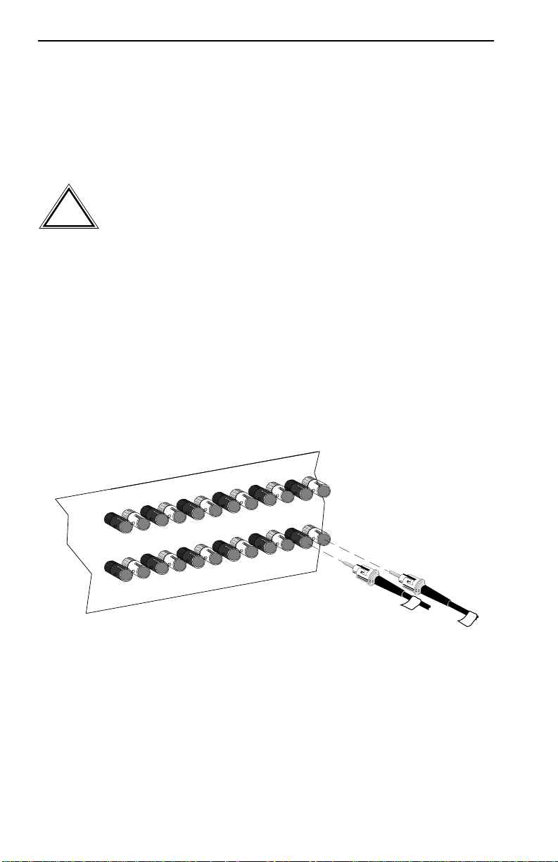
Use the following steps to connect a fiber optic link segment to the SEHI:
1. Remove the protective plastic covers from the fiber optic ports on the
applicable port on the module and from the ends of the connectors on
each fiber strand.
2. Attach the fiber labeled 1 to the applicable RX port, on the SEHI. See
Figure 5-1.
TX
RX
TX
RX
TX
RX
TX
RX
TX
RX
TX
RX
11
12
RX
TX
RX
6
TX
RX
TX
5
9
10
RX
4
TX
RX
TX
3
8
RX
2
7
TX
1
09032_09
1
2
Figure 5-1 SEHI-22FL Network Ports
5-2 SEHI User’s Guide
Page 35

Connecting the SEHI to the Network
3. Attach the fiber labeled 2 to the applicable TX port, on the SEHI.
4. At the other end of the fiber optic cable, attach the fiber labeled 1 to
the transmit port of the device.
5. Attach the fiber labeled 2 to the receive port.
6. Check that the LNK LED for the appropriate port is on. If the LED is
off, perform the following steps until it is on:
a. Check that the power is turned on for the device at the other end of
the link.
b. Verify proper crossover of fiber strands between the applicable
port on the SEHI and the fiber optic device at the other end of the
fiber optic link segment.
c. Verify that the fiber connection meets the dB loss specifications
outlined in Chapter 3.
If a link is not established, contact Cabletron Systems Technical Support.
SEHI User’s Guide 5-3
Page 36
Chapter 5: Connecting to the Network
5.1.2 Connecting a UTP Segment to an EPIM-T
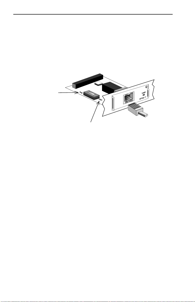
Before connecting a segment to the EPIM-T, check each end of the
segment to determine if the wires cross over for proper connection. If the
wires do not cross over, use the switch on the EPIM-T to internally cross
over the RJ45 port. Figure 5-2 shows the pin assignment of the port
according to the switch position.
Position X
(crossed over)
1. RX+
2. RX-
3. TX+
4. NC
5. NC
6. TX-
7. NC
8. NC
Position =
(not crossed over)
1. TX+
2. TX-
3. RX+
4. NC
Figure 5-2 EPIM-T Crossover Switch
5. NC
6. RX-
7. NC
8. NC
1490_14
To connect an EPIM-T to a twisted pair segment:
1. Connect the segment to the module by inserting the RJ45 connector on
the segment into the RJ45 port on the module. See Figure 5-2.
2. Check that the EPIM LNK LED is on. If the LED is off, perform each
of the following steps until it is on:
a. Check that the device at the end of the segment is powered up.
b. Verify that the RJ45 connector on the twisted pair segment has the
proper pinouts.
c. Check the cable for continuity.
d. Check that the twisted pair connection meets dB loss and cable
specifications outlined in Chapter 3, Section 3.1.3.
e. Check that the crossover switch is in the correct position.
5-4 SEHI User’s Guide
Page 37

Connecting the SEHI to the Network
If a link is not established, contact Cabletron Systems Technical Support.
5.1.3 Connecting a Fiber Segment to an EPIM-F1/F2/F3
When connecting a fiber optic link segment to an EPIM-F1, F2, or F3
keep the following in mind:
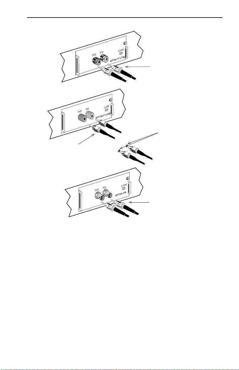
• When connecting a fiber optic link segment with SMA 906 connectors
to an EPIM-F1 with SMA ports, ensure that the half alignment sleeves
(shown in Figure 5-3) are in place on each connector. A full alignment
sleeve will damage the recei ve port. SMA 905 connectors do not need
alignment sleeves.
• Connect a segment with ST connectors to an EPIM-F2 or EPIM-F3 by
inserting the connector into the port with the alignment key on the
connector inserted into the alignment slot on the port. Turn the
connector clockwise to lock it down.
• The physical communication link consists of two strands of fiber optic
cabling: the Transmit (TX) and the Recei ve (RX). The TX strand from
the applicable port on the module connects to the receive port of a fiber
optic Ethernet device at the other end of the segment. The RX strand
of the applicable port on the module connects to the transmit port of
the fiber optic Ethernet device.
• Label the fiber optic cable to indicate which fiber is receive and which
is transmit. Fiber optic cable purchased from Cabletron Systems is
labeled so that one fiber is labeled 1, and the other fiber is labeled 2 at
both ends of the cable. For cable not purchased from Cabletron
Systems, label the cable as described above.
Do not touch the ends of the fiber optic strands, and do not let
the ends come in contact with dust, dirt, or other contaminants.
!
CAUTION
SEHI User’s Guide 5-5
Contamination of the ends causes problems in data
transmissions. If the ends become contaminated, clean them
with alcohol using a soft, clean, lint free cloth.
Page 38

Chapter 5: Connecting to the Network
Connect a fiber optic link segment to an EPIM-F1, EPIM-F2, or an
EPIM-F3 as follows:
1. Remove the protective plastic covers from the fiber optic ports on the
applicable port on the module and from the ends of the connectors on
each fiber strand.
2. Attach the fiber labeled 1 to the applicable RX port on the module. See
Figure 5-3.
3. Attach the fiber labeled 2 to the applicable TX port on the module.
4. At the other end of the fiber optic cable, attach the fiber labeled 1 to
the transmit port of the device.
5. Attach the fiber labeled 2 to the receive port.
6. Check that the EPIM LNK LED is on. If the LED is off, perform the
following steps until it is on:
a. Check that the power is on for the device at the end of the link.
b. Verify that the fiber strands are properly crossed over between the
applicable port on the module and the fiber optic device at the
other end of the fiber optic link segment.
c. Verify that the fiber connection meets the dB loss specifications
outlined in fiber optic network requirements.
If a link is not established, contact Cabletron Systems Technical Support.
5-6 SEHI User’s Guide
Page 39
F1/F2
SMA 905 Connectors
F3
Connecting the SEHI to the Network
ST Connectors
F1/F2
SMA 906 Connectors w/
Half Alignment Sleeves
ST Connectors
1490_15
Figure 5-3 The EPIM-F1, EPIM-F2, and EPIM-F3
SEHI User’s Guide 5-7
Page 40

Chapter 5: Connecting to the Network
5.1.4 Connecting a Thin Coaxial Segment to an EPIM-C
To connect a thin coaxial segment to an EPIM-C:
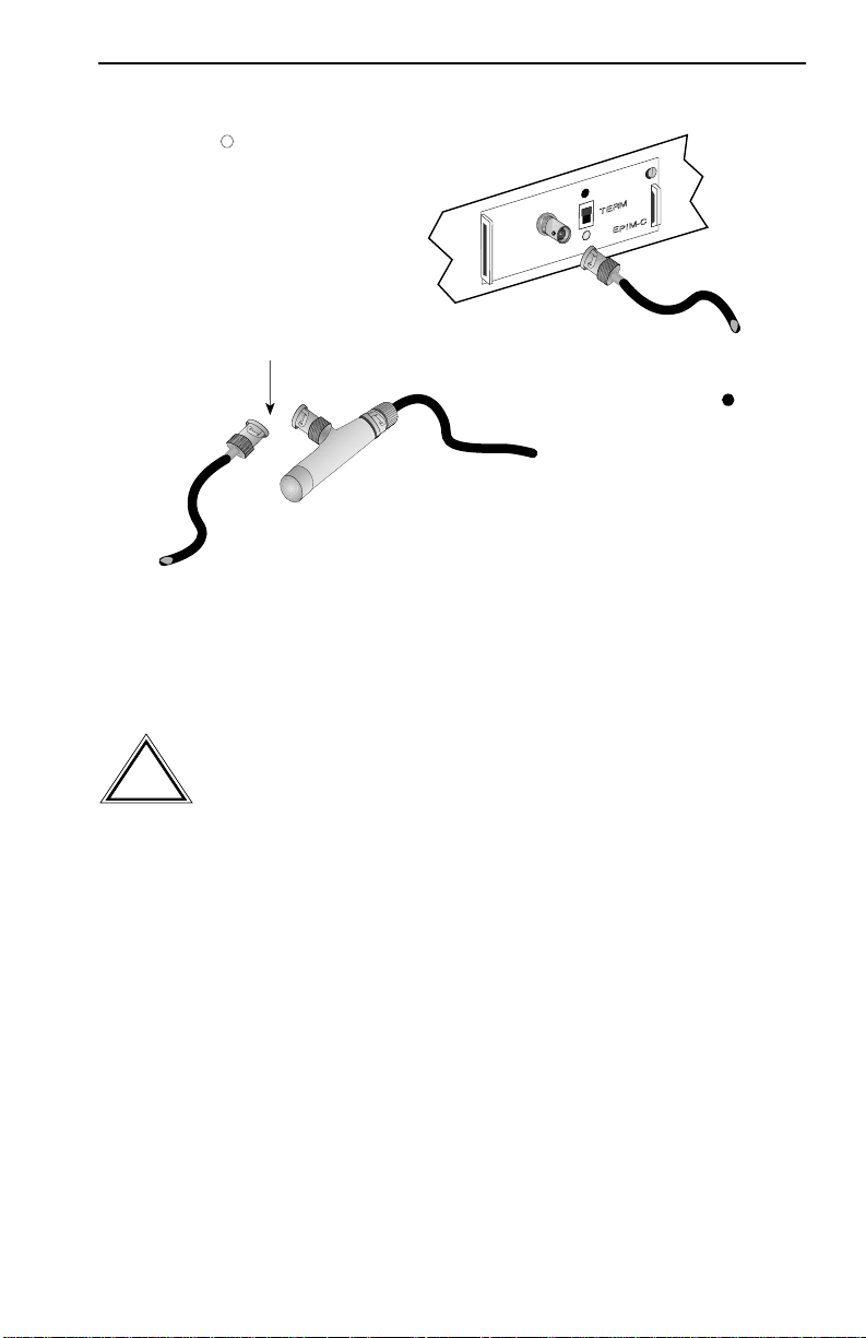
1. Set the Internal Termination Switch, located to the right of the port and
labeled TERM to one of the following:
• The On position (
•) if the thin coaxial segment connected directly
to the port is internally terminated at the port
• The Off position (o) if the thin coaxial segment is not internally
terminated at the port or externally terminated
2. If the Internal Termination switch is in the On position, connect the
thin coaxial segment directly to the BNC port as shown in Figure 5-4.
3. If the Internal Termination switch is in the Off position, proceed with
the following steps:
a. Attach a BNC T-connector to the BNC port on the module.
b. Attach the thin coaxial segment to one of the female connectors on
the T-connector.
NOTE
Terminate each segment attached to the T-connector. If a
segment is not attached to one of the female connections on
the T-connector, place a terminator on that connection.
c. Attach another thin coax segment or a terminator to the other
female connector on the T-connector.
For safety, ground only one end of a thin coaxial segment. Do
NOT connect EPIM BNC ports to earth ground. Connecting a
thin coaxial segment to earth ground at more than one point
could produce dangerous ground currents.
5-8 SEHI User’s Guide
Page 41
Connecting the SEHI to the Network
When internal termination switch
is set to Off ( ) follow these
procedures:
Connect BNC T-connector to port.
Attach a terminator or terminated
thin coaxial segment to one female
connector of T-connector.
Connect a terminated thin coaxial
segment to other female connector
of T-connector.
Figure 5-4 The EPIM-C
Attach thin coaxial segment directly to
BNC connector when internal
termination switch is set to On ( ).
5.1.5 Connecting an AUI Cable to an EPIM-A
1490_16
Ensure that the Signal Quality Error (SQE or “heartbeat”) test
function is disabled on the external transceiver connected to
!
CAUTION
the SEHI. The SEHI will not operate and the network will be
unusable if the transceiver has the SQE test function enabled.
Refer to the applicable transceiver manual.
Connect an EPIM-A to an external network segment as follows:
1. Attach an external transceiver to the network segment to be connected
to the AUI port. Refer to the applicable transceiver manual.
2. Attach an AUI cable no longer than 50 meters in length to the
transceiver connected to the network in step 1.
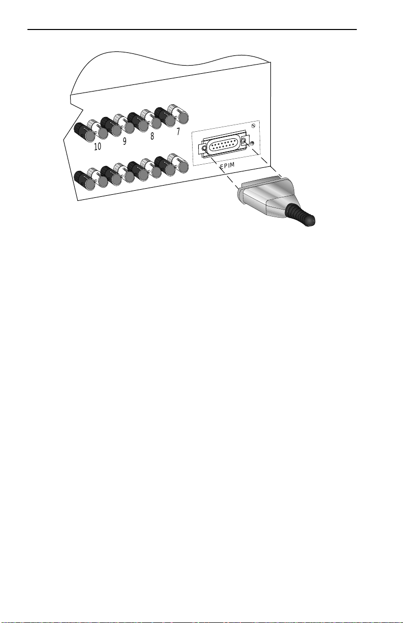
3. Connect the AUI cable to the EPIM-A. (See Figure 5-5.)
4. Lock the AUI connector into place using the connector slide latch.
SEHI User’s Guide 5-9
Page 42
Chapter 5: Connecting to the Network
TX
RX
TX
RX
TX
RX
TX
RX
TX
4
10
RX
TX
9
RX
3
TX
TX
RX
1
2
7
8
EPIM-1
1651_01
EPIM-A
PWR
165213
Figure 5-5 The EPIM-A
5. Check that the PWR LED on the EPIM-A is on. If the LED is not on,
contact Cabletron Systems Technical Support.
6. If the PWR LED is on with the AUI cable disconnected, continue with
the following checks:
a. Check the AUI connections for proper pinouts. The pinouts for the
transceiver connection are listed in Chapter 3.
b. Check the cable for continuity.
c. Reconnect the AUI cable to the SEHI and the device.
If the LED is still not on after reconnecting the segment, contact
Cabletron Systems Technical Support.
5-10 SEHI User’s Guide
Page 43
Connecting the SEHI to the Network
5.1.6 Connecting an AUI Cable to an EPIM-X
The Signal Quality Error (SQE) switch remains in the OFF
position for most network connections. However, some Data
!
CAUTION
Perform the following steps to connect an EPIM-X to a device not
requiring SQE:
1. Check that the SQE LED on the EPIM-X is off. If the SQE LED is on,
Terminal Equipment (DTE) requires SQE. Refer to a DTE
manual for SQE requirement information.
check the position of the SQE switch.
NOTE
If the SQE light remains on, even though the SQE switch is in
the OFF position, contact Cabletron Systems Technical
Support.
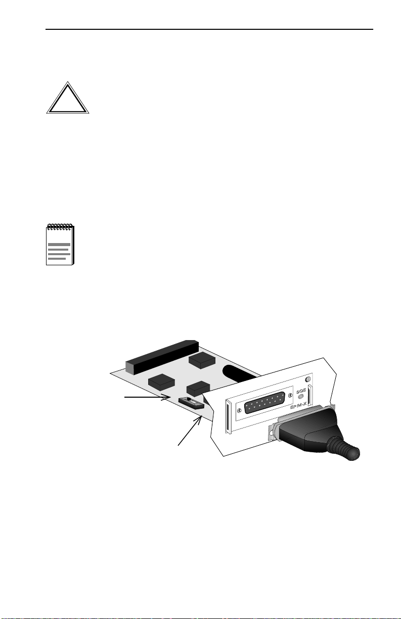
2. Attach one end of an AUI cable of up to 50 meters in length to the port
located on the EPIM-X (Figure 5-6) and connect the other end to the
intended node.
ON Position
(Toward Back
of EPIM)
ON
OFF
OFF Position
(Toward Front
of EPIM)
1490_18
Figure 5-6 The EPIM-X
SEHI User’s Guide 5-11
Page 44

Chapter 5: Connecting to the Network
5.2 FINISHING THE INSTALLATION
The SEHI is now ready for operation. Before placing the network into
service, test the installation thoroughly, making sure that all stations can
be addressed and that the SEHI and all stations are indicating normal
operation. Ensure that the networking software is configured properly to
match the installed network. If there are any errors or abnormal operation,
proceed to Chapter 6, Troubleshooting.
5-12 SEHI User’s Guide
Page 45

CHAPTER 6
TROUBLESHOOTING
This chapter contains instructions for using LANVIEW LEDs to
troubleshoot physical layer network problems. It also describes how to
reset the SEHI and how to reset the NVRAM switch.
6.1 INSTALLATION CHECKOUT
After connecting the SEHI to the network, verify that the packets pass
between all Ethernet devices connected to the SEHI and any other de vices
connected to the network. If there is a problem with any of the attached
devices, check the link as follows:
1. Check that the LNK LED, if applicable, for the port is on. If the LED
is off, proceed with the following steps:
a. Check that the 10BASE-FL device at the other end of the fiber
optic segment is powered up and that the TX and RX fibers are
properly connected.
b. For twisted pair EPIMs such as the EPIM-T, verify that the
connector on the twisted pair segment has the proper pinouts.
Refer to Chapter 3 for the pin assignments for twisted pair
connectors.
For the SEHI 10BASE-FL ports and the EPIM-F1, EPIM-F2, or
EPIM-F3 check that the TX and RX fibers are properly connected.
c. Check the cable for continuity. Several tools are available for this
test, depending on the media used.
d. Check that the twisted pair segments meet cable specifications for
dB loss as described in Chapter 3.
SEHI User’s Guide 6-1
Page 46

Chapter 6: Troubleshooting
2. If the remote station is ready and the LNK LED is on, but no data
passes through the port, one of the following two conditions may exist:
• Network management disabled the port.
• The port is segmented either because the collision detector was on
for more than 110 µs or the SEHI detected more than 32
consecutive collisions on the attached segment. The affected port
remains segmented until a good packet is transmitted/received
without collisions.
If the LNK LED is still off, contact Cabletron Systems Technical
Support.
6.2 USING LANVIEW
The SEHI incorporates the Cabletron Systems LANVIEW status
monitoring and diagnostics system. LANVIEW LEDs help diagnose
problems such as power failure or cable fault. The SEHI uses the
following LANVIEW LEDs:
• PWR, for power status
• CPU, for board status
• RCV (Receive), LNK (Link), and CLN (Collision) for Ethernet
status.
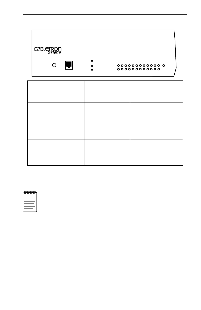
Figure 6-1 provides a quick reference chart of LED locations and
definitions. This chapter also includes a detailed description of each LED.
6-2 SEHI User’s Guide
Page 47
Using LANVIEW
HubSTACK 10BASE-T HUB WITH LANVIEW
SEHI-22FL
PWR
RESET
COM
LED NAME
PWR
(Power)
CPU
(Central Processing Unit)
CLN
(Collision)
RCV
(Receive)
LNK
(Link)
Figure 6-1 LANVIEW LEDs
CPU
CLN
LED COLOR
Off
Green (Solid)
Off
Green (Flashing)
Green (Blinking)
Red (Solid)
Red
Yellow (Flashing)
Off
Green
Off
®
SECURE
RCV
LNK
12 11 10 9 8 7 6 5 4 3 2 1
DEFINITION
No power
Power
CPU in BOOT process
CPU initializing
CPU functioning
CPU not functioning
Collision
SEHI is receiving data
No activity
Link established
No link
E
1
165214
NOTE
Blinking indicates a steady LED pulse.
PWR
When this green LED is on, it indicates that the SEHI is receiving power.
If this LED is off, it indicates a loss of input power. Check the input
power source (circuit breaker, fuse, etc.). If the proper source power is
present, the problem could be with the SEHI.
Flashing indicates an irregular LED pulse.
CPU
This LED alternates from red to green during power up. After the boot is
complete, the LED blinks green. A blinking green LED indicates normal
operation. A red LED indicates a faulty processor.
SEHI User’s Guide 6-3
Page 48

Chapter 6: Troubleshooting
CLN
This red LED indicates that a collision has occurred on one of the ports.
RCV
When a yellow RCV LED flashes, it indicates that the SEHI is receiving
data packets from the associated port segment. Each SEHI port has a
corresponding RCV LED. The network RCV port LEDs are labeled 1-12
and the EPIM-1 RCV port LED is labeled E-1.
LNK
When a green LNK LED is on, it indicates an established link between
the associated port and the device at the other end of the segment. The
LNK LED remains on as long as a link is maintained. Each SEHI
Network Port (ports 1–12) has a corresponding LNK LED.
6.3 USING THE RESET BUTTON
The SEHI incorporates a recessed RESET button. See Figure 6-1. The
RESET button initializes the SEHI processor. This button does NOT
initialize Non-Volatile Random Access Memory (NVRAM), the
nonvolatile random access memory where the SEHI stores network
management parameters.
To use the RESET button, use a pen or pencil to press the button. When
this is done, the SEHI initializes itself.
6-4 SEHI User’s Guide
Page 49
Setting the NVRAM Switch
6.4 SETTING THE NVRAM SWITCH
To prevent the possibility of electrical shock, do not remove the
chassis cover to access the NVRAM switch, and use only a
non-metallic tool when moving the NVRAM switch.
The SEHI uses NVRAM (Non-Volatile Random Access Memory) to store
user-entered parameters such as IP address and Community Names. To
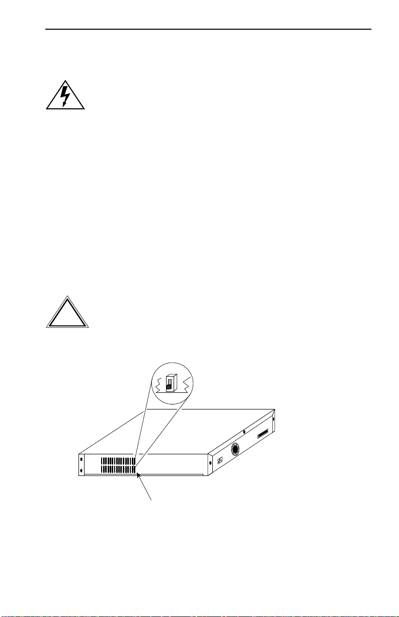
reset these parameters to the factory defaults, refer to Figure 6-2 and
perform the following steps:
1. With the power ON and using a non-metallic tool, move the NVRAM
switch to the UP position.
2. Press the RESET switch located on the front panel.
3. Wait until the unit boots (approximately 12 seconds).
4. Return the NVRAM switch to the DOWN position.
Failure to return the NVRAM switch to the DOWN position
results in loss of user-entered parameters upon power
!
CAUTION
shutdown and restart. The SEHI clears NVRAM if the unit is
restarted with the switch in the UP position.
Rear of Chassis
NVRAM Switch located behind grating
165215
Figure 6-2 NVRAM Switch Location
SEHI User’s Guide 6-5
Page 50

CHAPTER 7
LOCAL MANAGEMENT
This chapter explains how to set up a management terminal to access the
SEHI Local Management. It also explains how to use the Local
Management screens and commands.
Use Local Management to accomplish the following tasks:
• Assign an IP address and subnet mask.
• Select a default gateway.
• Control access to the SEHI through the community names established
in the Community Name Table.
• Designate which Network Management Workstations receive trap
messages from the device.
• Navigate through the Management Information Base (MIB) and
manage the objects within it from a remote location. Given the
appropriate security level, the MIB is accessible from the SEHI
through SNMP Tools.
Local Management also allows the user to manage each non-intelligent
stackable hub attached to the SEHI, and provides a Statistics screen to
view error, collision, and traffic statistics for the entire stack, individual
module, or individual port.
SEHI User’s Guide 7-1
Page 51

Chapter 7: Local Management
7.1 LOCAL MANAGEMENT KEYBOARD
CONVENTIONS
All key names appear in this manual as capital letters. For example, the
enter (return) key appears as ENTER and the space bar appears as SPACE
bar. Table 7-1 explains the keyboard conventions used in this manual as
well as the key functions.
Table 7-1 Keyboard Conventions
Key Function
RETURN Key and ENTER Key These are selection keys that perform
the same Local Management
function. For example, “Press
ENTER” means press either ENTER
or RETURN, unless this manual
specifically instructs you otherwise.
SPACE bar and BACKSPACE Key These keys cycle through selections
in some Local Management fields.
Use the SPACE bar to cycle forward
through selections and use
BACKSPACE to cycle backward
through selections.
Arrow Keys These are navigation keys. Use the
UP-ARROW, DOWN-ARROW,
LEFT-ARROW, and RIGHT-ARROW
keys to move the screen cursor. For
example, “Use the arrow keys”
means to press whichever arrow key
moves the cursor to the desired field
on the Local Management screen.
7-2 SEHI User’s Guide
Page 52

Management Terminal Setup
7.2 MANAGEMENT TERMINAL SETUP
Use one of the following systems to access Local Management:
• A Digital Equipment Corporation VT series terminal
• A VT type terminal running emulation programs for the Digital
Equipment Corporation VT series
• An IBM or compatible PC running a VT series emulation software
package
Use a console cable to attach the management terminal to the SEHI. The
console cable is not included with the SEHI, but can be purchased
separately from Cabletron Systems as part number SEHI-ACCY-KIT.
The SEHI-ACCY-KIT package provides an RJ45 Cable Kit that includes
the following:
• UTP console cable with RJ45 connectors on each end
• Adapters for DB9 or DB25 connections
• Instruction Sheet
The following sections explain ho w to attach the console cable and set up
the management terminal. Refer to the RJ45 Cable Kit Instruction Sheet
for adapter pinouts and additional information.
SEHI User’s Guide 7-3
Page 53
Chapter 7: Local Management
Console Cable Configuration
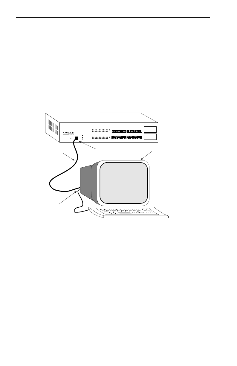
Use the RJ45 Cable Kit provided with the SEHI-ACCY-KIT package to
attach the management terminal to the SEHI COM port as shown in
Figure 7-1.
Connect the console cable to the SEHI as follows:
1. Attach the male RJ45 connector to the COM port of the SEHI.
2. Attach the female end (25-pin or 9-pin, as applicable) to the COM port
on the terminal.
Console Cable
COM Port
Figure 7-1 Management Terminal Connection
HubSTACK 10BASE-T HUB WITH LANVIEW®
SEHI-24
COM
COM RJ45 Port
EPIM-2
EPIM-1
Management Terminal
09162_17
7-4 SEHI User’s Guide
Page 54

Management Terminal Setup
Management Terminal Setup Parameters
Table 7-2 lists the setup parameters for the local management terminal. If
the terminal is a Digital Equipment Corporation VT320 terminal, press F3
to access the Setup Directory. If the Local Management terminal uses
terminal emulation of the VT320, refer to the equipment user manual for
setup procedures.
Table 7-2 Terminal Setup Parameters
Menu Function Selection
Columns 80 Columns
Display Setup:
General Setup:
Communications
Setup:
Keyboard Setup:
Controls Interpret Controls
Auto Wrap No Auto Wrap
Test Cursor Cursor
Mode 7 Bit Control
Cursor Keys Normal Cursor Keys
Transmit Transmit = 9600
Receive Receive = Transmit
XOFF Any Option
Bits, Parity 8 Bits, No Parity
Stop Bit 1 Stop Bit
Local Echo No Local Echo
Port
Transmit Any Option
Auto Answerback No Auto Answerback
Auto Repeat Any Option
Keyclick Any Option
Margin Bell Margin Bell
Warning Bell Warning Bell
Auto Answerback No Auto Answerback
DEC-423,
Data Leads Only
SEHI User’s Guide 7-5
Page 55

Chapter 7: Local Management
7.3 ACCESSING LOCAL MANAGEMENT
After configuring the local management terminal and properly attaching
the cables to the SEHI, access the Local Management interface.
1. Power up the terminal. The password screen (Figure 7-2) appears.
SEHI LOCAL MANAGEMENT
Cabletron SEHI Revision X.XX.XX
Cabletron Systems Incorporated
35 Industrial Way, P.O. Box 5005
Rochester, NH 03867-0505 U.S.A.
(603) 332-9400
(c) Copyright Cabletron Systems, Inc. 1993
SEHI F/W Version: X.XX.XX
Boot Prom Version: X.XX.XX
SEHI Board Version: X.X
EnterUser Password:
1490_21
Figure 7-2 Password Screen
2. Enter the Password. The factory default password for Super-User
access is “public” or press ENTER.
NOTE
The password is one of the community names specified in the
Community Name Table. Access to certain Local Management
capabilities depends on the degree of access accorded that
community name. Refer to Section 7.5 for more details about
community names.
3. Press ENTER.
• If the password entry is inv alid, the cursor returns to the beginning
of the password entry field.
• If the password is valid, the associated access privilege appears
briefly, then the SEHI Local Management Feature Selection
screen shown in Figure 7-3 appears.
7-6 SEHI User’s Guide
Page 56

The Feature Selection Screen
NOTE
Management session ends and the screen defaults to the
Password screen.
If the terminal keyboard is not used for 15 minutes, the Local
SEHI LOCAL MANAGEMENT
Cabletron Systems Incorporated
P.O. Box 5005 Rochester, NH 03867-0505 U.S.A.
(603) 332-9400
FEATURE SELECTION
F6 COMMUNITY NAME TABLE
F7 IP ADDRESS ASSIGNMENT
F8 COMPONENT TRAP TABLE
F9 SNMP TOOL SUPPORT
DEVICE STATISTICS
EXIT LIM SERVICE
1490_22
Figure 7-3 Feature Selection Screen
7.4 THE FEATURE SELECTION SCREEN
The Feature Selection screen is the main menu screen for SEHI Local
Management. There are five screen options in the Feature Selection
screen: Community Name Table, IP Address Assignment, Component
Trap Table, SNMP Tool Support, and Device Statistics. Use the arrow
keys to highlight an option, then press ENTER (or press the
corresponding Function Key). The selected screen appears.
To exit your Local Management session, use the arrow keys to highlight
the EXIT LIM SERVICE command, then press ENTER.
SEHI User’s Guide 7-7
Page 57

Chapter 7: Local Management
7.5 THE COMMUNITY NAME TABLE SCREEN
To access the Community Name Table screen from the Feature Selection
screen, use the arrow keys to highlight the Community Name Table
option, then press ENTER or F6. The Community Name Table screen
shown in Figure 7-4 appears.
SEHI LOCAL MANAGEMENT
Cabletron SEHI Revision X.XX.XX
COMMUNITY NAME TABLE
COMMUNITY NAME ACCESS
PUBLIC
PUBLIC
PUBLIC
PUBLIC
SAVE IP TABLE TRAP TABLE SNMP TOOLS RETURN
F6 F7 F8 F9
BASIC-READ
READ-ONLY
READ-WRITE
SUPER-USER
1490_23
Figure 7-4 Community Name Table Screen
Community names are set through the Community Name Table option.
Community names are passwords to Local Management and are agents of
security control to the SEHI. SEHI access is controlled by establishing up
to four different levels of security authorization: Basic-Read, Read-Only,
Read-Write, and Super-User.
With Super-User access, the user changes the existing passwords by
changing the community names. Only the community name assigned
Super-User access has full management privileges.
The following sections explain each field on the Community Name Table
screen and provides instructions on how to change them.
COMMUNITY NAME
Displays the user-defined name through which a user can access Local
Management for the SEHI. Any community name assigned here acts as a
password to Local Management.
7-8 SEHI User’s Guide
Page 58

The Community Name Table Screen
ACCESS
Indicates the access status accorded each community name. Possible
conditions are as follows:
BASIC-READ This allows Read-Only access to Local
Management, but excludes read privileges to
the Component Trap screen.
READ-ONLY This allows Read-Only access to Local
Management, but excludes access to security
protected fields of the upper levels of
authorization (Read-Write or Super-User).
READ-WRITE This allows the user to read and write to Local
Management fields, excluding IP Address,
Subnet Mask, and Community Names.
SUPER-USER This access privilege gives the user read and
write access to Local Management. Super-User
allows read and write access to all modifiable
parameters including: Community Names, IP
Addresses, Traps, and SNMP Objects.
Editing the Community Name Field
The password used to access Local Management at the Password screen
must have Super-User privileges for the edits to take effect. If a password
is entered with Basic-Read, Read-Only, or Read-Write privileges, Local
Management displays the message “AUTHORIZATION PROHIBITS
ACCESS”, and does not include editing capabilities.
To edit the Community Name field:
1. Use the arrow keys to highlight the Community Name field adjacent
to the desired access level.
2. Enter the community name (maximum of 32 characters) into the field.
3. Press ENTER.
4. Repeat steps 1–3 for editing any of the other community names.
5. Use the arrow keys to highlight the SAVE command at the bottom of
the screen, then press ENTER or F6. The “SAVED OK” message
appears indicating that the edits have been saved to memory.
SEHI User’s Guide 7-9
Page 59

Chapter 7: Local Management
NOTE
the changes, a “NOT SAVED?” message is displayed. The
edits are lost if the user exits without saving the changes.
6. To exit the screen, press the appropriate Function key or use the arrow
keys to highlight the RETURN command.
7. Press ENTER. The Feature Selection screen appears.
7.6 THE CONFIGURATION SCREEN
T o access the Configuration screen from the Feature Selection screen, use
the arrow keys to highlight the IP Address Assignment option, then
press ENTER or F7. The screen shown in Figure 7-5 appears.
SEHI LOCAL MANAGEMENT
Cabletron SEHI Revision X.XX.XX
CONFIGURATION
I/F IP Address SubNET Mask MAC Address
1 000.000.000.000 000.000.000.000 00-00-1d-05-dc-
The first time a user attempts to exit the screen without saving
36
Serial Port 1 Application: CONSOLE Baud Rate: 9600 --ACTIVE-
-
Port Enable Override: OVERRIDE DISABLED
Default Gateway: 0.0.0.0
SAVE COMMUNITY NAMES TRAP TABLE SNMP TOOLS RETURN
F6 F7 F8 F9
1490_24
Figure 7-5 Configuration Screen
Assign the IP Address, Subnet Mask, and Default Gateway through this
screen. Use the Port Enable Override option to enable all device ports in
the stack and override the Port Disable setting in the Statistics screen.
7-10 SEHI User’s Guide
Page 60

The Configuration Screen
The following sections explain each field on the Configuration screen.
I/F
The number of the interface corresponding to the channels over which
packets with that IP Address pass. On the SEHI, this value is “1.”
IP Address
Displays the IP address of the SEHI.
SubNET Mask
Displays the subnet mask for the SEHI. A subnet mask is a 32-bit quantity
which “masks out” the network bits of the IP address. Do this by setting
the bits in the mask to 1 when the network treats the corresponding bits in
the IP address as part of the network or subnetwork address, or to 0 if the
corresponding bit identifies the host.
MAC Address
Displays the physical address associated with the interface.
Default Gateway
Displays the default gateway for the SEHI. This field is not defined until
an appropriate value is entered. The default gateway identifies the default
gateway device that forwards packets to other IP subnetworks.
Serial Port Application
Displays the port application setting as CONSOLE.
Baud Rate
Displays the Baud Rate setting of the device attached to the SEHI through
the serial port. The setting for the serial port is 9600.
Port Enable Override
This command lets the user override the Disable Port settings in the
Device Statistics screen to enable all ports in the stack.
SEHI User’s Guide 7-11
Page 61
Chapter 7: Local Management
Setting the IP Address
Use the following steps to set the IP Address:
1. Use the arrow keys to highlight the IP Address field.
2. Enter the IP address into this field. The format for this entry is
XXX.XXX.XXX.XXX, with values for XXX being from 0 to 255.
The screen beeps if non-numerics or adjacent dots are entered. If the
entry does not have three dots, it is rejected.
3. Press ENTER. The IP address appears and the natural subnet mask for
the user is generated and also appears.
4. Use the arrow keys to highlight the SAVE option, then press ENTER
or F6. The “SAVED OK” message appears indicating that the changes
have been saved to memory.
NOTE
Setting the Subnet Mask
NOTE
The first time an attempt is made to exit the screen without
saving the changes, a “NOT SAVED?” message is displayed.
The edits are lost if the user proceeds to exit without saving the
changes.
Consult the Network Administrator prior to setting the Subnet
Mask.
The subnet mask defines how the SEHI treats SNMP Trap IP destination
addresses in its Trap Table.
• Set the subnet mask when workstations in the Trap Table reside on a
different subnet (i.e., across a gateway or router), and these
workstations are to receive SNMP traps.
• Use the subnet mask factory default setting of 0.0.0.0 when all trap
designated workstations are on the SEHI subnet.
Use the following steps to set the subnet mask:
1. Use the arrow keys to highlight the SubNET Mask field.
7-12 SEHI User’s Guide
Page 62

The Configuration Screen
2. Enter the subnet mask into this field. The format for this entry is
XXX.XXX.XXX.XXX with values for XXX being from 0 to 255.
3. Press ENTER.
4. Use the arrow keys to highlight the SAVE option, then press ENTER
or F6. The “SAVED OK” message appears indicating that the changes
have been saved to memory.
NOTE
Setting the Default Gateway
The first time an attempt is made to exit the screen without
saving the changes, a “NOT SAVED?” message is displayed.
The edits are lost if the user proceeds to exit without saving the
changes.
The Default Gateway field allows the user to identify the router through
which the SEHI will be forwarding IP packets.
Use the following steps to set the Default Gateway:
1. Use the arrow keys to highlight the Default Gateway field.
2. Enter the gateway default mask in this field. The format for this entry
is XXX.XXX.XXX.XXX with values for XXX being from 0 to 255.
3. Press ENTER. If the entry is accepted as a valid default gateway,
“OK” appears to the right of the field.
4. Use the arrow keys to highlight the SAVE option, then press ENTER
or F6. The “SAVED OK” message appears indicating that the changes
have been saved to memory.
Using the Port Enable Override
Use the following steps to override the Disable Port settings and enable
all ports in the stack:
1. Use the arrow keys to highlight the Port Enable Override field.
2. Press ENTER to toggle from the default setting of “OVERRIDE
DISABLED” to “OVERRIDE ENABLED.”
3. The adjacent field displays “Y/N.” Enter Y to continue enabling all
ports, or N to discontinue the port enable override. The message
“PORT ENABLED” appears after Y is entered.
SEHI User’s Guide 7-13
Page 63

Chapter 7: Local Management
Exiting the Configuration Screen
Use the following steps to exit the Configuration screen and return to the
Feature Selection screen:
1. Press the appropriate Function key. To return to the Feature Selection
screen, use the arrow keys to highlight the RETURN command.
2. Press ENTER. The Feature Selection screen appears.
7.7 THE TRAP TABLE SCREEN
Access the Trap Table screen from the Features Selection screen using the
arrow keys to highlight the Component Trap Table option, then press
ENTER or F8. The screen shown in Figure 7-6 appears.
SEHI LOCAL MANAGEMENT
Cabletron SEHI Revision X.XX.XX
TRAP T ABLE
SNMP Community Name
<CR>
<CR>
<CR>
<CR>
<CR>
<CR>
<CR>
<CR>
SAVE COMMUNITY NAMES IP TABLE SNMP TOOLS RETURN
F6 F7 F8 F9
Traps
N
N
N
N
N
N
N
N
IP Address
0.0.0.0
0.0.0.0
0.0.0.0
0.0.0.0
0.0.0.0
0.0.0.0
0.0.0.0
0.0.0.0
1490_25
Figure 7-6 Trap Table Screen
The Trap Table defines the management stations that will receive SNMP
Traps for alarm/event notification. The following sections explain each
field on the Trap Table screen and instructions on how to change them.
SNMP Community Name
Displays the community name included in the trap message sent to the
network management station with the associated IP address.
7-14 SEHI User’s Guide
Page 64

The T rap Tab le Screen
Traps
Enables transmission of the traps to the network management station with
the associated IP address.
IP Address
Indicates the IP address of the workstation receiving trap alarms from the
SEHI.
Configuring the Trap T able
Use the following steps to configure the Trap table:
1. Use the arrow keys to highlight the SNMP Community Name field,
then enter the community name.
2. Press ENTER.
3. Use the arrow keys to highlight the Traps field and enter Y (or y) to
send alarms from the SEHI to the workstation, or N (or n) to prevent
alarms from being sent.
4. Press ENTER.
5. Use the arrow keys to highlight the appropriate IP Address field.
6. Enter the IP address of the workstation to send traps to in this field.
The format for this entry is XXX.XXX.XXX.XXX, with the value of
XXX ranging from 0 to 255, and three dots, or else it returns to the
beginning of the field.
7. Use the arrow keys to highlight the SAVE option, then press ENTER
or F6. The “SAVED OK” message appears indicating that the changes
have been saved to memory.
Exiting the Trap T able Screen
Use the following steps to exit the Trap Table screen and return to the
Feature Selection screen:
1. Press the appropriate Function key. To exit to the Feature Selection
screen, use the arrow keys to highlight the RETURN command.
2. Press ENTER. The Feature Selection screen appears.
SEHI User’s Guide 7-15
Page 65

Chapter 7: Local Management
7.8 THE SNMP TOOLS SCREEN
This section describes how to use the SNMP Tools screen to access
Management Information Bases (MIBs). Access to screen options
depends on the access status accorded to the user’s community name.
This section describes Super-User management capabilities.
SNMP Tools allows access to valuable MIB information. The user gets
information about specific object identifiers (OIDs), edits the values of
configurable OIDs, and requests the OID numerically sequential to the
originally requested OID.
Other ways to view OIDs from the SNMP Tools screen include Walking,
Stepping, and Cycling. Walk and Cycle let the user review se veral OIDs at
a time.
To access the SNMP T ools screen from the Features Selection screen, use
the arrow keys to highlight the SNMP Tools Support option, then press
ENTER or F9. The SNMP Tools screen shown in Figure 7-7 appears.
SEHI LOCAL MANAGEMENT
Cabletron SEHI Revision X.XX.XX
SNMP TOOLS
SNMP COMMUNITY NAME: public
OID PREPEND: 1.3.6.1
GET SET GETNEXT WALK RECALL-OID STEP CYCLES REPEAT
F6 F7 F8 F9
RETURN
F10
1490_26
Figure 7-7 SNMP Tools Screen
The following sections describe SNMP Tools screen fields.
SNMP COMMUNITY NAME
Identifies the community name used as a password to determine access
level to the MIB component.
7-16 SEHI User’s Guide
Page 66

The SNMP Tools Screen
OID PREPEND
Specifies the number prefix common to all Object Identifiers (OIDs)
found in the MIBs – 1.3.6.1 is the default prefix OID. This is a modifiable
field.
GET
Allows the user to retrieve MIB objects using SNMP protocol.
SET
Allows users with Read-Write and Super-User access to change
modifiable MIB objects, using SNMP protocol.
GETNEXT
Displays the OID following the current OID.
WALK
Allows the user to scroll through a section of the MIB leaf by leaf, from a
user-specified object identifier. Leaves are the sections of the OID
separated by periods. When a walk is initialized, the following categories
for each walk entry, or step are displayed.
• Specified OID - gives the number tag for that OID.
• Size - identifies the number of bytes required to store that object.
• Type - specifies the variable type of the object (e.g., int = integer).
• Data - displays what the object identifier represents.
RECALL-OID
Recalls, from memory, the last OID used.
STEP
Displays the MIB walk, step by step, giving the user time to view specific
leaves in detail.
CYCLES
Allows the user to specify the number of GETNEXT requests to cycle
through and how much time will elapse between each request.
REPEAT
Repeats the last Get command, allowing the user to monitor changes to a
specific OID.
SEHI User’s Guide 7-17
Page 67

Chapter 7: Local Management
Getting Individual OIDs
Use the following steps to “Get” individual OIDs:
1. Highlight GET, using the arrow keys, then press ENTER or F6.
“<GET> OID (=|F9)” appears.
2. Use one of the following options to enter the OID:
• Using the keyboard to enter the OID minus the prepend (e.g., if the
prepend is 1.3.6.1, and 4.1.3 is entered, then the
OID=1.3.6.1.4.1.3).
• Entering an “
=” and the OID suffix (e.g., if =4.1.3 is entered, then
the OID=4.1.3). This allows the user to digress and not use the
prepend.
• Pressing F9 to recall an OID already entered. The user can then
use the keyboard to modify the recalled OID as necessary.
3. Press ENTER. If there is no instance of that OID, the return code will
specify “MIB_NO_INSTANCE”, otherwise, information about that
OID data type, length, and value appear.
Getting the Next OID
Use the following steps to “Get” the next OID:
1. Highlight GETNEXT with the arrow keys, then press ENTER or F8.
“<GETNEXT> OID (=|F9)” appears.
2. Enter the desired OID, or OID extension. (Press F9 to recall the last
OID request. The recalled OID may then be modified as necessary.)
3. Press ENTER. If there is no instance of that OID, the return code will
specify “MIB_NO_INSTANCE”, otherwise, information about that
OID data type, length, and value appear.
Setting an OID
Use the following steps to “Set” the next OID:
1. Highlight SET by using the arrow keys, then press ENTER or F7.
“<SET> OID (=|F9)” appears.
2. Enter the OID, minus the OID prepend. If the OID was previously
entered, pressing F9 recalls that entry. The arrow keys may be used to
modify the recalled OID if necessary.
7-18 SEHI User’s Guide
Page 68

The SNMP Tools Screen
3. Press ENTER. If there is no instance of that OID, the return code will
specify “MIB_NO_INSTANCE”, otherwise “DATA TYPE:”
appears.
4. Enter the data type for that OID. Possible choices are integer, string,
null, OID, IP address, counter, gauge, timeticks, and opaque.
5. Press ENTER. “DATA” appears.
6. Enter the value to correspond to the OID. If accepted, “<SET>
OPERATION CODE: XXXX <OK>” appears, otherwise an error
message appears.
Viewing Multiple OIDs
View several OIDs at one time to scan a MIB for specific information.
“WALK” scrolls through OIDs numerically sequential to the initial OID
request. “STEP” scrolls the MIB Walk, one OID at a time. Cycling allows
the user to specify how many GETNEXT commands to cycle through.
Walking Through OIDs
Use the following steps to “Walk” through OIDs:
1. Highlight WALK, using the arrow keys, then press ENTER.
“<INITIAL> OID (=|F9)” appears.
2. Enter the OID (minus the prepend) and press ENTER. The screen
begins walking through the sublayers of the MIB available from the
specified OID. Each OID listed displays the specified OID, its size, its
type, and the data it contains.
3. Press the SPACE bar to stop the walk, or wait for “***MIB WALK
COMPLETED***” to appear on the screen.
Stepping Through OIDs
Use the following steps to “Step” through OIDs (the user can step through
only after a GETNEXT):
1. Highlight STEP, using the arrow keys, then press ENTER. “Specify
OID” appears.
2. Enter the OID (only the suffix is necessary) and press ENTER. The
Tools screen begins to scroll one OID at a time, through all of the
sublayers of the MIB available for that OID.
SEHI User’s Guide 7-19
Page 69

Chapter 7: Local Management
Cycling Through OIDs
Use the following steps to “Cycle” through OIDs:
1. Use the arrow keys to Highlight CYCLES, then press ENTER.
2. Enter the number of cycles desired to occur after “ENTER CYCLE
COUNT:”, then press ENTER.
3. Enter how many seconds delay desired between get next requests after
“ENTER CYCLE DELAY (secs):”, then press ENTER.
Exiting the SNMP Tools Screen
Use the following steps to exit the SNMP Tools screen:
1. Use the arrow keys to highlight the RETURN command.
2. Press ENTER. The Feature Selection screen appears.
7.9 THE DEVICE STATISTICS SCREEN
This section describes the features of the Device Statistics screen. The
user can view error , collision, and traf fic statistics for the stack, a selected
module, or a selected port. The user can also enable and disable ports.
To access the Statistics screen from the Features Selection screen, use the
arrow keys to highlight the Device Statistics option, then press ENTER.
The Device Statistics screen shown in Figure 7-8 appears.
SEHI LOCAL MANAGEMENT
Cabletron SEHI Revision X.XX.XX
DEVICE STATISTICS
ST ACK T OTAL
BYTES RECEIVED:
FRAMES RECEIVED:
ERRORS RECEIVED:
COLLISIONS:
OOW COLLISIONS:
CRC ERRORS:
ALIGNMENT ERRORS:
RUNT PACKETS:
GIANT PACKETS:
PORT ADMIN. STATUS:
PORT SEG. STATUS:
ENABLE PORT DISABLE PORT
UPDATE -FREQ 3 Sec MODULE 1 PORT 1 RETURN
3792125
16547
0
0
0
0
0
0
0
0
MODULE: 1
67960
255
0
0
0
0
0
0
0
0
Figure 7-8 Device Statistics Screen
7-20 SEHI User’s Guide
PORT: 1
67960
255
0
0
0
0
0
0
0
0
ENABLE
UNSEGMENTED
1490_27
Page 70

The Device Statistics Screen
The following sections describe Device Statistics screen fields:
BYTES RECEIVED
Displays the number of bytes received.
FRAMES RECEIVED
Displays the number of frames received.
ERRORS RECEIVED
Displays the number of errors received.
COLLISIONS
Displays the number of collisions received.
OOW COLLISIONS
Displays the number of Out Of Window collisions. OOW collisions are
usually caused by the network being too long where the round trip
propagation delay is greater than 51.2 µs (the collision domain is too
large), a station somewhere on the network is violating Carrier Sense and
transmitting at will, or a cable somewhere on the network failed during
the transmission of the packet.
CRC ERRORS
Displays the number of packets with bad Cyclic Redundancy Checks
(CRC) that have been received from the network. The CRC is a 4-byte
field in the data packet that ensures that the transmitted data that is
received is the same as the data that was originally sent.
ALIGNMENT ERRORS
Displays the number of errors due to misaligned packets.
RUNT PACKETS
Displays the number of runt packets received from the network. A runt
packet is less than the minimum Ethernet frame size of 64 bytes, not
including preamble.
GIANT PACKETS
Displays the number of packets received whose size exceeded 1518 data
bytes, not including preamble.
SEHI User’s Guide 7-21
Page 71

Chapter 7: Local Management
PORT ADMIN. STATUS
Displays the administrative status of the port selected. The two possible
status messages are Enable or Disable.
PORT SEG. STATUS
Displays the segmentation status of the port selected. The two possible
status messages are Segmented or Unsegmented. The SEHI and SEH
automatically partition problem segments, and reconnect non-problem
segments to the network.
ENABLE PORT
This command lets the user enable the selected port.
DISABLE PORT
This command lets the user disable the selected port.
UPDATE-FREQ
This command lets the user select the time interval between
Stack/Module/Port counter updates. Choose update intervals up to 99
seconds in increments of 3 seconds.
MODULE
This command lets the user view statistics for a selected module in the
stack. The SEHI is Module 1 and each SEH in the stack follows in
sequential order. Figure 7-9 shows each module number in the stack.
SEH - MODULE 5
SEH - MODULE 4
SEH - MODULE 3
SEH - MODULE 2
SEHI - MODULE 1
1490_28
Figure 7-9 Module Number Sequence
7-22 SEHI User’s Guide
Page 72

The Device Statistics Screen
PORT
This command lets the user view port statistics for ports 1-26 of the
selected module.
Selecting the Appropriate Module/Port
When the Device Statistics screen first appears, statistics are displayed for
Module 1 and Port 1. To view statistics for another module and port, use
the Module x or Port x commands at the bottom of the screen.
To select a module or port:
1. Use the arrow keys to highlight the Module or Port command.
2. Press the SHIFT and
+ keys, or the SHIFT and - keys until the desired
module or port number appears.
3. Press ENTER. Statistics associated with the selected Module and Port
appear.
Using the ENABLE PORT Command
The ENABLE PORT command lets the user enable the selected port. The
user must first use the PORT command to select the desired port.
Use the following steps to set the ENABLE PORT command:
1. Use the arrow keys to highlight the ENABLE PORT command at the
bottom of the screen.
2. Press ENTER. The corresponding port is enabled and the Port Admin
Status field is updated.
SEHI User’s Guide 7-23
Page 73

Chapter 7: Local Management
Using the DISABLE PORT Command
The DISABLE PORT command lets the user disable the port selected in
the PORT command. The user must first use the Port command to select
the desired port.
To set the DISABLE PORT command:
1. Use the arrow keys to highlight the DISABLE PORT command at the
bottom of the screen.
2. Press ENTER. The corresponding port is enabled and the Port Admin
Status field is updated.
Exiting the Device Statistics Screen
Use the following steps to exit the Device Statistics screen and return to
the Feature Selection screen:
1. Use the arrow keys to highlight the RETURN command at the bottom
of the screen.
2. Press ENTER. The Feature Selection screen appears.
7-24 SEHI User’s Guide
Page 74
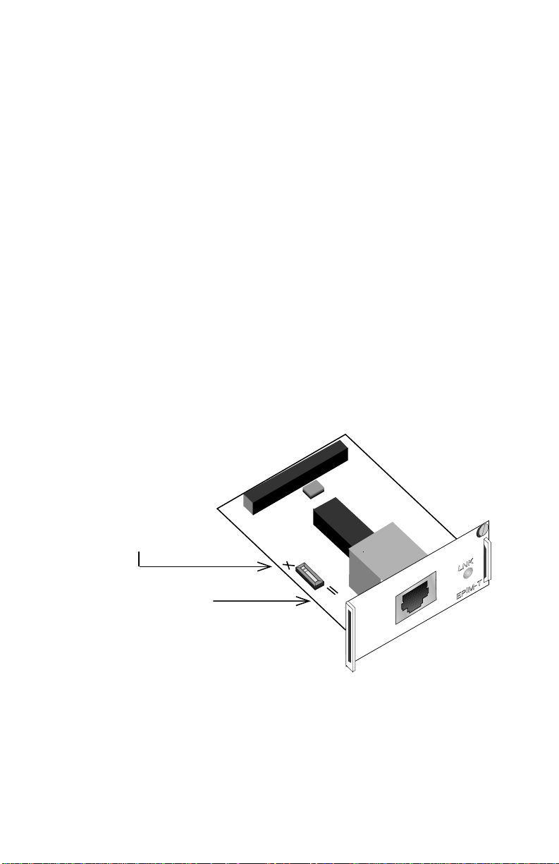
APPENDIX A
EPIM INFORMATION
A.1 EPIM SPECIFICATIONS
EPIMs enable the connection of the SEHI to the main network using
different media types. Cabletron Systems offers a variety of EPIMs. The
following sections explain specifications for each EPIM.
A.1.1 EPIM-T
The EPIM-T is an RJ45 connector supporting UTP cabling. It has an
internal Cabletron Systems TPT-T 10BASE-T Twisted Pair Transceiver.
The slide switch on the EPIM-T determines the crossover status of the
cable pairs. If the switch is on the
over. If the switch is on the
over. Figure A-1 shows the pinouts for the EPIM-T in both positions.
Position X
(crossed over)
X side, the pairs are internally crossed
= side, the pairs are not internally crossed
1. RX+
2. RX-
3. TX+
4. NC
SEHI User’s Guide A-1
5. NC
6. TX-
7. NC
8. NC
Position =
(not crossed over)
1. TX+
2. TX-
3. RX+
4. NC
5. NC
6. RX
7. NC
8. NC
Figure A-1 EPIM-T Pinouts
1490_29
Page 75
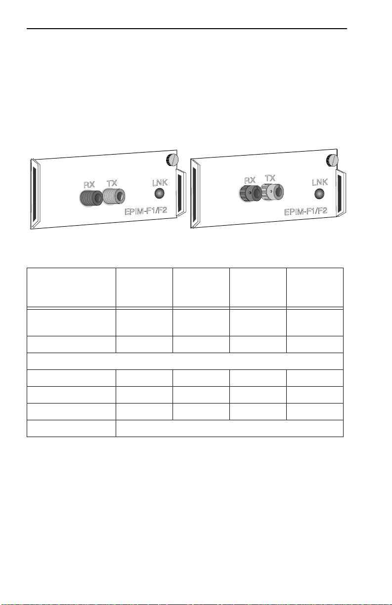
Appendix A: EPIM Information
A.1.2 EPIM-F1 and EPIM-F2
The EPIM-F1 and EPIM-F2 shown in Figure A-2 support Multimode
Fiber Optic cabling. Each EPIM has an internal Cabletron Systems
FOT-F Fiber Optic Transceiver. The EPIM-F1 is equipped with SMA
Connectors and the EPIM-F2 is equipped with ST Connectors.
Specifications for the EPIMs are listed below.
1490_30
Figure A-2 EPIM-F1 and EPIM-F2
Parameter
Receive
Sensitivity -30.5 dBm -28.0 dBm
Peak Input Power -7.6 dBm -8.2 dBm — —
Transmitter Power
50/125 µm fiber -13.0 dBm -15.0 dBm 13.0 dB 17.5 dB
62.5/125 µm fiber -10.0 dBm -12.0 dBm 16.0 dB 20.5 dB
100/140 µm fiber -7.0 dBm -9.0 dBm 19.0 dB 23.5 dB
Error Rate Better than 10
Typical
Value
Worst
Case
-10
Worst
Case
Budget
——
Typical
Budget
1490_31
The transmitter power levels and receive sensitivity levels listed are Peak
Power Lev els after optical overshoot. Use a Peak Po wer Meter to compare
the values giv en above to those measured on any particular port. If Power
Levels are being measured with an Average Power Meter, add 3 dBm to
the measurement to compare the measured values to the values listed (i.e.
-33.5 dBm average + 3 dBm =-30.5 dBm peak).
A-2 SEHI User’s Guide
Page 76
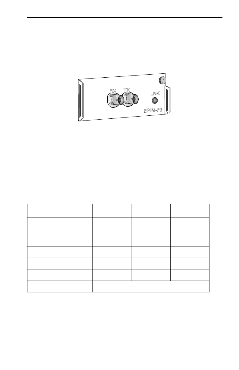
EPIM Specifications
A.1.3 EPIM-F3
The EPIM-F3 (Figure A-3) supports Single Mode Fiber Optic cabling. It
has an internal Cabletron Systems FOT-F Fiber Optic Transceiver and is
equipped with ST Connectors. EPIM-F3 specifications are listed below.
1490_32
Figure A-3 EPIM-F3
Transmitter Power decreases as temperatures rise and increases as
temperatures fall. Use the Output Power Coefficient to calculate increased
or decreased power output for the operating environment. For example,
the typical power output at 25°C is -16.4 dBm. For a 4°C temperature
increase, multiply the typical coefficient (-0.15 dBm) by four and add the
result to typical output power (4 x -0.15 dBm + -16.4 = -17.0).
Parameter Typical Minimum Maximum
Transmitter Peak
Wave Length 1300 nm 1270 nm 1330 nm
Spectral Width 60 nm - 100 nm
Rise Time 3.0 ns 2.7 ns 5.0 ns
Fall Time 2.5 ns 2.2 ns 5.0 ns
Duty Cycle 50.1% 49.6% 50.7%
Bit Error Rate Better than 10
-10
The transmitter power levels given above are Peak Power Levels after
optical overshoot. Use a Peak Power Meter to compare the values given
above to those measured on any particular port. If you are using an
Average Power Meter, add 3 dBm to the measurement to compare the
average power values to the values listed above
(i.e., -33.5 dBm average + 3 dBm = -30.5 dBm peak).
SEHI User’s Guide A-3
Page 77
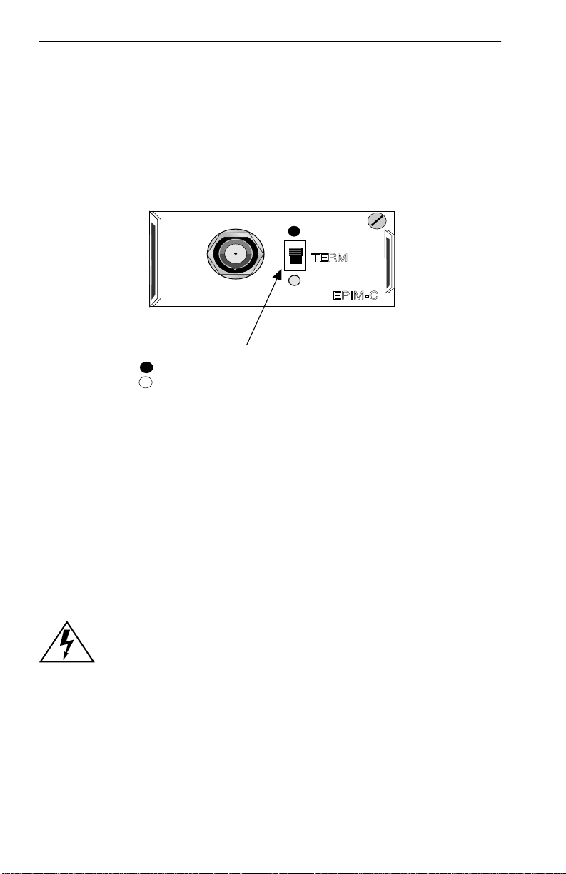
Appendix A: EPIM Information
A.1.4 EPIM-C
The EPIM-C supports thin coaxial cabling and is equipped with an
internal Cabletron Systems TMS-3 Transceiver. Use the TERM switch on
the front of the EPIM-C to set the internal 50-ohm terminator. This
eliminates the need to connect the port to a T-connector and terminator.
Figure A-4 shows the setting for the terminator switch.
TERM
EPIM-C
Internal Termination Switch
= On (internally terminated)
= Off (need external termination)
1490_34
Figure A-4 EPIM-C
Connector Type
BNC receptacle, with gold center contact, for use with BNC type
T-connectors and RG58 thin coaxial cable.
Grounding
The BNC port of the Coaxial Interface Module is not connected to earth
ground.
z
A-4 SEHI User’s Guide
For safety, ground only one end of a thin coaxial segment. Do
NOT connect EPIM BNC ports to earth ground. Connecting a
thin coaxial segment to earth ground at more than one point
can produce dangerous ground currents.
Page 78
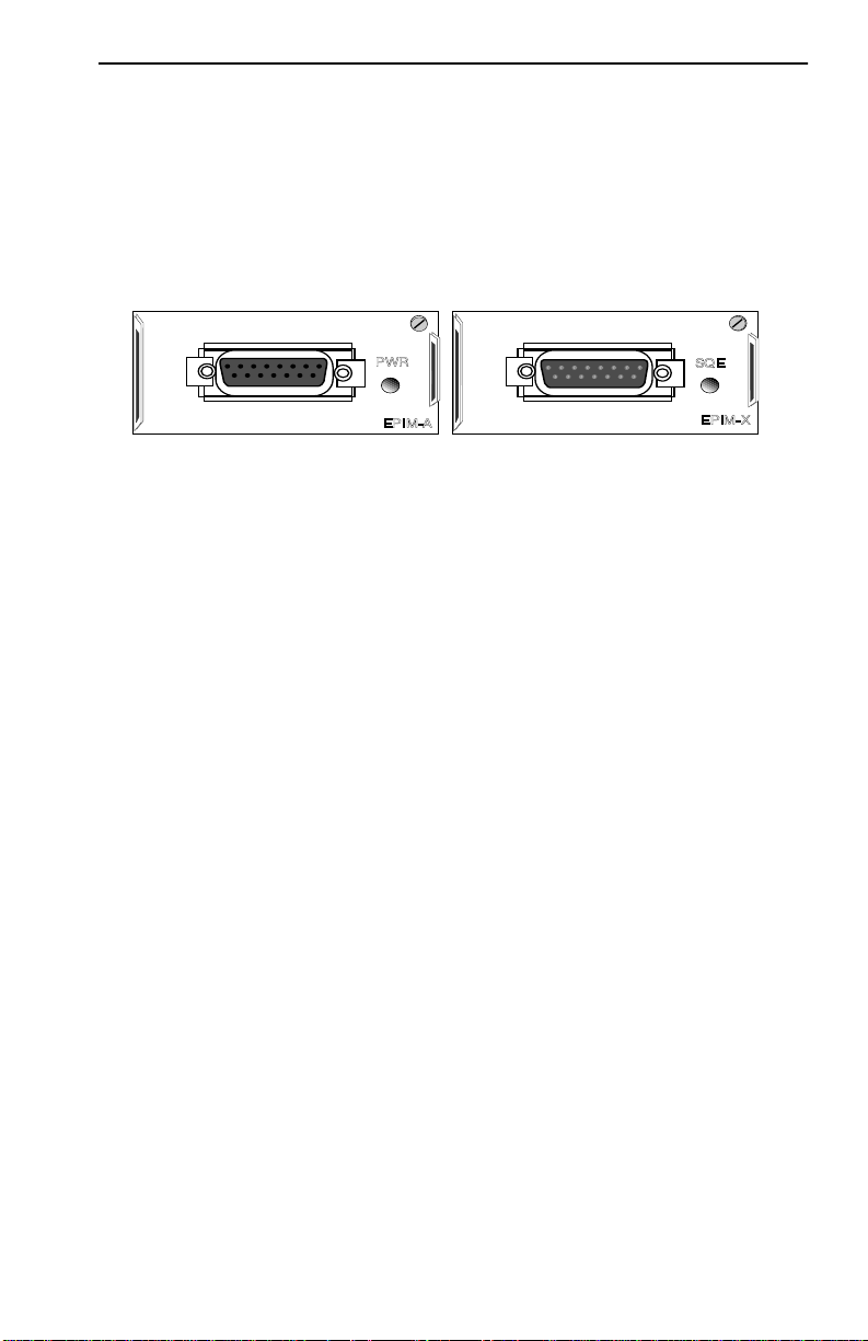
EPIM Specifications
A.1.5 EPIM-A and EPIM-X (AUI Port)
The EPIM-A is a DB15 female connector used to attach segments to an
external transceiver. The EPIM-X is equipped with dual internal
transceivers. It has a DB15 male connector used to attach segments to an
AUI cable. Figure A-5 shows both modules.
1490_35
Figure A-5 The EPIM-A and EPIM-X
Pin 1 Logic Ref. 9 Collision -
2 Collision + 10 Transmit 3 Transmit 11 Logic Ref.
4 Logic Ref. 12 Receive 5 Receive + 13 Power (+12Vdc)
6 Power Return 14 Logic Ref.
7 No Connection 15 No Connection
8 Logic Ref.
Connector Shell: Protective Ground
SEHI User’s Guide A-5
Page 79

APPENDIX B
IMAGE FILE DOWNLOAD USING OIDs
This appendix provides instructions for setting up a TFTP server and to
download an image file to the SEHI by setting specific MIB OID strings.
Set the OID strings with the SNMP Tools screen described in Chapter 7,
Section 7.8.
NOTE
Download an image file to the SEHI with a remote
management package such as SPECTRUM, SPECTRUM
Element Manager, or the appropriate SPECTRUM Portable
Management Application. Refer to the specific package
documentation for image file download procedures.
The SEHI supports the Standard TFTP Download application. In this
application the SEHI automatically goes offline during the image
download. After the download, the SEHI programs FLASH, then reboots
with the new image.
Before downloading the image to the SEHI, you must complete the
following steps:
1. Decompress the image file on a DOS PC using the PKUNZIP utility
included with the image.
NOTE
The PKUNZIP utility requires a DOS PC. You must
decompress the image file on the DOS PC before you load the
image file onto the TFTP server.
2. Load the decompressed image file onto the TFTP server.
NOTE
SEHI User’s Guide B-1
For information on how to set up a workstation as a TFTP
server, ref er to your specific workstation documentation. These
instructions include limited information and guidelines for
setting up a UNIX workstation to work as a TFTP server.
Page 80

Appendix B: Image File Download Using OIDs
B.1 SETTING UP A UNIX WORKSTATION AS A TFTP
SERVER
Due to variations between UNIX systems and individual configurations,
this section provides only GUIDELINES for configuring a UNIX
workstation to perform an image file download. The instructions include
command examples, where appropriate. Bold lettering in examples
indicates operator entry.
If unsure about how to properly configure a UNIX workstation
using these guidelines, contact the Systems Administrator.
!
CAUTION
To set up a UNIX workstation, proceed as follows:
1. Edit the /etc/ethers file by adding the SEHI MAC address, followed by
a unique name (e.g., 00:00:1d:32:0c:1b sehi).
2. Edit the /etc/hosts file by adding the SEHI MAC address and follow it
with the same unique name used in step 1 (e.g., 00:00:1d:32:0c:1b
sehi).
3. If the workstation already has a /tftpboot directory, confirm the TFTP
setup of the workstation as follows:
Request a process status and grep for TFTP (e.g., unix% ps-aux | grep
tftp).
The following information represents a typical output:
user 161 7.7 1.2 32 184 p3 S 12:00 grep tftp
root 87 0.0 0.9 48 136 ? S 11:05 tftp -s
The term tftp -s , located at the end of the root string, indicates TFTP is
active. If TFTP is NOT running, only the grep process appears.
4. If the workstation does NOT have a /tftpboot directory, than create one
(e.g., unix% mkdir tftpboot).
5. Ensure that the /tftpboot directory is not owned (e.g., unix% chown
nobody tftpboot).
B-2 SEHI User’s Guide
Page 81

Standard TFTP Download
NOTE
The next step requires decompression of the zipped image file.
If you do not have a UNIX unzip utility, access to a PC with
PKUNZIP, or a way to FTP the decompressed image to your
UNIX workstation, contact Cabletron Systems Technical
Support.
6. Store the hex image file in the /tftpboot directory as sehi.hex.
7. Edit the /etc/inetd.conf file by removing anything prior to the tftpboot
daemon (e.g., the # sign) that comments-out the line.
8. Kill the inetd process (e.g., unix% kill -HUP ‘process ID number’),
and then restart the process (e.g., unix% inetd), to enable the revised
inetd.conf file.
NOTE
The user must request a process status and grep for inetd to
obtain the process ID number (refer to step 3).
B.2 STANDARD TFTP DOWNLOAD
Table B-1 provides a step-by-step procedure for downloading the
firmware image file. This section provides specific MIB OIDs, MIB
names, and the required setting for proper image file download. Refer to
the specific MIB walking tool documentation for instructions on how to
set MIB OID strings.
The Download OIDs for CabletronSystems products reside in Cabletron
Systems enterprise MIBs (group 52). The specific OIDs necessary to
perform an image file download reside in the common download group
under
ctDL (Cabletron Download). The full OID string to reach this group is
1.3.6.1.4.1.52.4.1.5.8.1.
When performing the steps in Table B-1, keep the following in mind:
• Follow the steps in order.
• Enter the IP address of the TFTP server in standard dotted decimal
notation (e.g., 132.177.118.24).
SEHI User’s Guide B-3
Page 82

Appendix B: Image File Download Using OIDs
• Enter the FULL path to the image file in the ctDLTFTPRequest OID,
including the name of the image file (e.g., c:/tftpboot/sehi.hex).
Table B-1 Standard TFTP Download Procedure
Step OID Name OID Number
1. ctDLForceOnBoot 1.3.6.1.4.1.52.4.1.5.8.1.1.0 integer 1
2. ctDLCommitRAMToFlash 1.3.6.1.4.1.52.4.1.5.8.1.2.0 integer 1
3. ctDLTFTPRequestHost 1.3.6.1.4.1.52.4.1.5.8.1.4.0
4. ctDL TFTPRequest 1.3.6.1.4.1.52.4.1.5.8.1.5.0
5. ctDLInitiateColdBoot 1.3.6.1.4.1.52.4.1.5.8.1.3.0 integer 1
Data
Type
IP
address
string
(ASCII)
SNMP OID
Data
Enter the
IP address
of the TFTP
server.
Enter the
path to the
image file.
B-4 SEHI User’s Guide
Page 83

INDEX
Numerics
10BASE-FL
attenuation 3-2
budget and propagation delay 3-2
cable requirements 3-2
10BASE-T
cable length 3-3
crosstalk 3-4
delay 3-3
impedance 3-3
insertion loss 3-3
jitter 3-3
noise 3-4
temperature 3-4
UTP and STP specifications 3-3
A
AUI cable 5-9, 5-11
C
Cable specifications 3-1
fiber optic 3-2
UTP and STP 3-3
Cables
HubSTACK Interconnect 2-4
COM Port 3-5
D
Default Gateway 7-13
Device Statistics screen 7-20
Dimensions 3-8
E
Environmental requirements 3-8
EPIM installation 4-9
EPIM specifications 2-4
EPIM-A and EPIM-X A-5
EPIM-C A-4
EPIM-F1/F2 A-2
EPIM-F3 A-3
EPIM-T A-1
F
FLASH EEPROMs 2-2
FLASH Firmware Image 4-1
H
Help
related manuals 1-3
HubSTACK
cable requirements 3-2
HubSTACK Interconnect cables 2-4
I
IP address 7-12
L
LANVIEW 6-2
LEDs 6-3
Local Management 7-1
accessing 7-6
community name table 7-8
configuration screen 7-10
console cable 7-4
device statistics 7-20
port ENABLE override 7-13
setting default gateway 7-13
setting IP address 7-12
setting subnet mask 7-12
SNMP tools 7-16
terminal requirements 7-3
terminal setup 7-5
trap table 7-14
SEHI User’s Guide Index-1
Page 84

Index
N
Network connection 5-1
AUI 5-9, 5-11
EPIM-A 5-9
EPIM-C 5-8
EPIM-F1/F2/F3 5-5
EPIM-T 5-4
EPIM-X 5-11
fiber optic segment 5-5
thin coaxial 5-8
Unshielded Twisted Pair 5-4
Network port specifications
SEHI-22FL 3-4
NVRAM
pre-installation checkout 4-2
setting 6-5
O
OIDs 7-16
Operating specifications 3-6
P
Port ENABLE override 7-13
Power supply requirements 3-7
T
Transceiver requirements 3-5
Trap Table screen 7-14
Troubleshooting 6-1
R
Rack mounting
accessory kit 2-4
Remote network management 2-3
Reset 6-4
S
Safety requirements 3-8
SEHI features 2-2
Size
dimensions 3-8
SNMP tools screen 7-16
Subnet mask 7-12
Index-2 SEHI User’s Guide
Page 85

POWER SUPPLY CORD
The mains cord used with this equipment must be a 2 conductor plus ground type
with minimum 0.75 mm square conductors and must incorporate a standard IEC
appliance coupler on one end and a mains plug on the other end which is suitable
for the use and application of the product and that is approved for use in the
country of application.
GERMAN:
Die Netzleitung, die mit diesem Geraet benuetzt wird, soll einen zwei Leiter mit
Erdleiter haben, wobei die Leiter mindestens 0.75 mm sind, mit einer normalen
IEC Geraetesteckdose an einem Ende und einem Geraetestecker am anderen Ende
versehen sind, der fuer den Gebrauch und die Anwendung des Geraetes geeignet
und der zum Benuetzen im Lande der Anwendung anerkannt ist.
SPANISH:
El cable principal de la red eléctrica utilizado con este equipo debe tener 2
conductores y 1 toma de tierra con un mínimo de 0.75 mm2 cada uno y necesita
tener un aparato de acoplamiento standard IEC en un extremo y un enchufe para
el cable principal de la red eléctrica en el otro extremo, lo cual sea adecuado para
el uso y applicación del producto y lo cual sea aprobado para uso en el pais de
applicación.
FRENCH:
Le cordon d' alimentation reliant cet appareil au secteur doit obligatoirement avoir
deux fils conducteurs de 0.75 mm2 minimum et un fil de terre. It doit également
être équipé du côté appareil d'une fiche agrée IEC et du côte secteur, d'une prise
adaptée à l'usage du produit et aux normes du pays où l'appareil est utilisé.
 Loading...