

Cabletron Systems SmartSTACK STS16-20RM, SmartSTACK STS16-20R, SmartSTACK STS16-20FRM Installation And User Manual

SmartStack
STS16-20RM/STS16-20FRM
Token Ring Switches
Installation
and
User Guide


Notice
Cabletron Systems reserves the right to make changes in specifications and other
information contained in this document without prior notice. The reader should in all
cases consult Cabletron Systems to determine whether any such changes have been made.
The hardware, firmware, or software described in this manual is subject to change
without notice.
IN NO EVENT SHALL CABLETRON SYSTEMS BE LIABLE FOR ANY
INCIDENTAL, INDIRECT, SPECIAL, OR CONSEQUENTIAL DAMAGES
WHATSOEVER (INCLUDING BUT NOT LIMITED TO LOST PROFITS) ARISING
OUT OF OR RELATED TO THIS MANUAL OR THE INFORMATION CONTAINED
IN IT, EVEN IF CABLETRON SYSTEMS HAS BEEN ADVISED OF, KNOWN, OR
SHOULD HAVE KNOWN, THE POSSIBILITY OF SUCH DAMAGES.
i
© October 1999 by:
Cabletron Systems, Inc.
35 Industrial Way
Rochester, NH 03867
All Rights Reserved.
Order Number: 9032957-01
(OC-7052 v. 1.1, 710001810)
SmartStack
CompuServe
i960 microprocessor
Ethernet
is a trademark of Cabletron Systems, Inc.
is a registered trademark of CompuServe, Inc.
is a registered trademark of Intel Corp.
is a trademark of Xerox Corporation.
Notice

ii
FCC Notice
This device complies with Part 15 of the FCC rules. Operation is subject to the following
two conditions: (1) this device may not cause harmful interference, and (2) this device
must accept any interference received, including interference that may cause undesired
operation.
NOTE:
digital device, pursuant to Part 15 of the FCC rules. These limits are designed to provide
reasonable protection against harmful interference when the equipment is operated in a
commercial environment. This equipment uses, generates, and can radiate radio
frequency energy and if not installed in accordance with the operator’s manual, may
cause harmful interference to radio communications. Operation of this equipment in a
residential area is likely to cause interference in which case the user will be required to
correct the interference at his own expense.
WARNING:
approved by the party responsible for compliance could void the user’s authority to
operate the equipment.
This equipment has been tested and found to comply with the limits for a Class A
Changes or modifications made to this device which are not expressly
VCCI Notice
This is a Class A product based on the standard of the Voluntary Control Council for
Interference by Information Technology Equipment (VCCI). If this equipment is used in
a domestic environment, radio disturbance may arise. When such trouble occurs, the user
may be required to take corrective actions.
Industry Canada Notice
This digital apparatus does not exceed the Class A limits for radio noise emissions from
digital apparatus set out in the Radio Interference Regulations of the Canadian
Department of Communications.
Le présent appareil numérique n'émet pas de bruits radioélectriques dépassant les limites
applicables aux appareils numériques de la class A prescrites dans le Règlement sur le
brouillage radioélectrique édicté par le ministère des Communications du Canada.
Notice

Declarati on of Co nformity
Addendum
iii
Application of Council Directive(s):
Manufacturer’s Name:
Manufacturer’s Address:
European Representative Name:
European Representative Address:
Conformance to Directive(s)/Product Standards:
Equipment Type/Environment:
89/336/EEC
73/23/EEC
Cabletron Systems, Inc.
35 Industrial Way
PO Box 5005
Rochester, NH 03867
Mr. J. Solari
Cabletron Systems Limited
Nexus House,
Newbury Business Park
London Road, Newbury
Berkshire RG13 2PZ, England
EC Directive 89/336/EEC
EC Directive 73/23/EEC
EN 55022
EN 50082-1
EN 60950
Networking Equipment, for use
in a Commercial or Light
Industrial Environment.
We the undersigned, hereby declare, under our sole responsibility, that the equipment
packaged with this notice conforms to the above directives.
Manufacturer Legal Representative in Europe
Mr. Ronald Fotino
Full Name Full Name
Principal Compliance Engineer
Title Title
Rochester, NH, USA
Location Location
Mr. J. Solari
Managing Director - E.M.E.A.
Newbury, Berkshire, England
Notice

iv
Table of Contents
1. Introduction 1
Switching Technology . . . . . . . . . . . . . . . . . . . . . . . 2
Switch of Switches. . . . . . . . . . . . . . . . . . . . . . . 2
Switch of Servers . . . . . . . . . . . . . . . . . . . . . . . 3
Switch of Hubs . . . . . . . . . . . . . . . . . . . . . . . . . 3
Switch of Desktops . . . . . . . . . . . . . . . . . . . . . . 3
Switch of Floors and Buildings. . . . . . . . . . . . . . . . . 4
Switch of Routers . . . . . . . . . . . . . . . . . . . . . . . 4
Front Panel Details . . . . . . . . . . . . . . . . . . . . . . . . 5
The MANAGEMENT Port . . . . . . . . . . . . . . . . . . . 5
Token Ring Ports . . . . . . . . . . . . . . . . . . . . . . . 6
Switched Port Analyzer . . . . . . . . . . . . . . . . . . . . 6
SmartStack Interface Modules. . . . . . . . . . . . . . . . . 7
Reset Button . . . . . . . . . . . . . . . . . . . . . . . . . . 7
System Request Button . . . . . . . . . . . . . . . . . . . . 7
Labels . . . . . . . . . . . . . . . . . . . . . . . . . . . . . 7
Status and Activity LEDs . . . . . . . . . . . . . . . . . . . 8
Back Panel Details. . . . . . . . . . . . . . . . . . . . . . . . . 10
Features and Specifications . . . . . . . . . . . . . . . . . . . . 11
Features . . . . . . . . . . . . . . . . . . . . . . . . . . . . 11
Specifications . . . . . . . . . . . . . . . . . . . . . . . . . 13
2. Switch Overview 17
Multiple Simultaneous Conversations . . . . . . . . . . . . . . . 18
Low Latency . . . . . . . . . . . . . . . . . . . . . . . . . . . . 19
Address Management . . . . . . . . . . . . . . . . . . . . . . . 19
Multiple Bridging Modes . . . . . . . . . . . . . . . . . . . . . . 20
Source Route Switching (SRS) . . . . . . . . . . . . . . . . 21
Source Route Bridging (SRB) . . . . . . . . . . . . . . . . . 21
Source Route Transparent (SRT) . . . . . . . . . . . . . . . 22
SRT/SRB . . . . . . . . . . . . . . . . . . . . . . . . . . . 22
Filtering . . . . . . . . . . . . . . . . . . . . . . . . . . . . . . 23
Congestion Control . . . . . . . . . . . . . . . . . . . . . . . . 23
Three Switching Modes . . . . . . . . . . . . . . . . . . . . . . 24
Cut-Through . . . . . . . . . . . . . . . . . . . . . . . . . . 24
Store and Forward . . . . . . . . . . . . . . . . . . . . . . . 24
Auto (Adaptive Cut-Through) . . . . . . . . . . . . . . . . . 24
Token Ring Port Operation Modes . . . . . . . . . . . . . . . . 25
RI/RO-Like Connection . . . . . . . . . . . . . . . . . . . . . . 26
Transmission Priority Queues . . . . . . . . . . . . . . . . . . . 27
Notice

ClearSession Support . . . . . . . . . . . . . . . . . . . . . . 27
CrossLink Connections. . . . . . . . . . . . . . . . . . . . . . 28
Spanning Tree Protocol Support . . . . . . . . . . . . . . . . . 29
VLAN Support . . . . . . . . . . . . . . . . . . . . . . . . . . 29
Dynamic Source Route Recovery . . . . . . . . . . . . . . . . 31
Management . . . . . . . . . . . . . . . . . . . . . . . . . . . 34
SNMP . . . . . . . . . . . . . . . . . . . . . . . . . . . . 34
SmartStack Manager for Windows . . . . . . . . . . . . . . 35
Telnet Management and VT100 Management (Console) . . 35
IBM LAN Network Manager . . . . . . . . . . . . . . . . . 35
RMON Support . . . . . . . . . . . . . . . . . . . . . . . . . . 36
Built-in Port Counters. . . . . . . . . . . . . . . . . . . . . . . 37
Stackable Architecture . . . . . . . . . . . . . . . . . . . . . . 38
Back-to-Back . . . . . . . . . . . . . . . . . . . . . . . . . 38
Internal Stacker. . . . . . . . . . . . . . . . . . . . . . . . 38
External Stacker . . . . . . . . . . . . . . . . . . . . . . . 38
Optional Redundant Power Supply. . . . . . . . . . . . . . . . 39
v
3. Preparing for Installation 41
Safety Recommendations . . . . . . . . . . . . . . . . . . . . 41
Safety with Electricity. . . . . . . . . . . . . . . . . . . . . 41
Preventing Electrostatic Discharge Damage . . . . . . . . . 42
Site Requirements . . . . . . . . . . . . . . . . . . . . . . . . 43
Environment . . . . . . . . . . . . . . . . . . . . . . . . . 43
Chassis Accessibility . . . . . . . . . . . . . . . . . . . . . 43
Cooling and Airflow. . . . . . . . . . . . . . . . . . . . . . 43
Power. . . . . . . . . . . . . . . . . . . . . . . . . . . . . 43
Configuration Guidelines . . . . . . . . . . . . . . . . . . . . . 45
Frame Length Limit. . . . . . . . . . . . . . . . . . . . . . 45
IEEE 802.1D Spanning Tree . . . . . . . . . . . . . . . . . 46
Ring Numbers . . . . . . . . . . . . . . . . . . . . . . . . 47
Connecting to Other Non-IEEE 802.5j Compliant
Fiber Devices. . . . . . . . . . . . . . . . . . . . . . . . . 47
Sample Applications for the STS16-20RM and
the STS16-20FRM . . . . . . . . . . . . . . . . . . . . . . . . 48
Important Management Considerations . . . . . . . . . . . 52
4. Installation 53
Installation Summary . . . . . . . . . . . . . . . . . . . . . . . 53
Package Contents . . . . . . . . . . . . . . . . . . . . . . . . 54
Materials Needed for Installation . . . . . . . . . . . . . . . . . 55
Installing a SmartStack Interface Module . . . . . . . . . . . . 55
Mounting the Chassis . . . . . . . . . . . . . . . . . . . . . . 57
Notice

vi
Rack or Cabinet Mounting . . . . . . . . . . . . . . . . . . . 57
Table-Mounting . . . . . . . . . . . . . . . . . . . . . . . . 58
Cabling. . . . . . . . . . . . . . . . . . . . . . . . . . . . . . . 59
Connecting Devices to the Token Ring Ports . . . . . . . . . 59
Connecting Devices to the Token Ring Ports
Using Building Wiring . . . . . . . . . . . . . . . . . . . . . 60
Checking the Installation. . . . . . . . . . . . . . . . . . . . . . 61
Applying Power . . . . . . . . . . . . . . . . . . . . . . . . . . 62
5. Accessing Switch Management 65
Overview . . . . . . . . . . . . . . . . . . . . . . . . . . . . . . 65
Connecting the Console . . . . . . . . . . . . . . . . . . . . . . 66
Communication Problems . . . . . . . . . . . . . . . . . . . 68
Diagnostic Screen . . . . . . . . . . . . . . . . . . . . . . . 69
6. Switch Configuration 71
General Guidelines . . . . . . . . . . . . . . . . . . . . . . . . 72
Navigating within the Menus. . . . . . . . . . . . . . . . . . 73
Main Menu . . . . . . . . . . . . . . . . . . . . . . . . . . . . . 74
Configuration Menu . . . . . . . . . . . . . . . . . . . . . . . . 75
Switch Configuration Screen. . . . . . . . . . . . . . . . . . . . 76
Stack Configuration Screen . . . . . . . . . . . . . . . . . . 79
Module Information Screen . . . . . . . . . . . . . . . . . . 80
VLAN Configuration . . . . . . . . . . . . . . . . . . . . . . . . 82
VLAN Configuration Menu . . . . . . . . . . . . . . . . . . . 83
VLAN Configuration Screen . . . . . . . . . . . . . . . . . . 84
VLAN Parameter Configuration for CRF Screen . . . . . . . 86
VLAN Parameter Configuration for BRF Screen . . . . . . . 88
VLAN Port Configuration Screen . . . . . . . . . . . . . . . 90
IP Configuration Screen . . . . . . . . . . . . . . . . . . . . . . 91
BootP Requests and Parameters . . . . . . . . . . . . . . . 93
SNMP Configuration Menu . . . . . . . . . . . . . . . . . . . . 94
Spanning Tree Protocol . . . . . . . . . . . . . . . . . . . . . . 94
IEEE 802.1D Spanning Tree Protocol (STP) . . . . . . . . . 95
Spanning Tree for BRF Screen . . . . . . . . . . . . . . . . 96
Spanning Tree for CRF Screen . . . . . . . . . . . . . . . . 99
Port Spanning Tree Parameters Screen. . . . . . . . . . . 102
Current Spanning Tree Information Screen . . . . . . . . . 103
Port Configuration Screen . . . . . . . . . . . . . . . . . . . . 104
Switched Port Analyzer Menu . . . . . . . . . . . . . . . . . . 109
CrossLink . . . . . . . . . . . . . . . . . . . . . . . . . . . . 109
CrossLink Menu . . . . . . . . . . . . . . . . . . . . . . . 111
CrossLink Configuration Screen . . . . . . . . . . . . . . . 112
Notice

vii
Setting up a CrossLink . . . . . . . . . . . . . . . . . . . . 113
Current CrossLink Information Screen . . . . . . . . . . . . 114
Address Filtering . . . . . . . . . . . . . . . . . . . . . . . . . 115
Filters and Port Security Menu . . . . . . . . . . . . . . . . 116
Configure Filters Screen . . . . . . . . . . . . . . . . . . . 117
Configure Port Security Mode Screen . . . . . . . . . . . . 119
View Port Filters Screen . . . . . . . . . . . . . . . . . . . 120
Protocol Filters Menu. . . . . . . . . . . . . . . . . . . . . 121
Protocol Class Assignment Screen . . . . . . . . . . . . . 122
Port Filtering Attributes Screen. . . . . . . . . . . . . . . . 123
Address Aging . . . . . . . . . . . . . . . . . . . . . . . . . . 125
Address Aging Menu . . . . . . . . . . . . . . . . . . . . 126
Port Address Table Aging Screen . . . . . . . . . . . . . . 126
Master Address Table Aging Screen . . . . . . . . . . . . . 128
Password Menu . . . . . . . . . . . . . . . . . . . . . . . . . 129
Console/Telnet Sessions . . . . . . . . . . . . . . . . . . . . . 131
Console Configuration Menu . . . . . . . . . . . . . . . . . 131
Serial Link Configuration Screen . . . . . . . . . . . . . . . 132
Creating a Console Session Using a Modem . . . . . . . . 133
Stopping the Console Session . . . . . . . . . . . . . . . . 133
Telnet Configuration Screen . . . . . . . . . . . . . . . . . 134
Telnet Sessions Screen . . . . . . . . . . . . . . . . . . . 135
Starting the Telnet Session. . . . . . . . . . . . . . . . . . 136
Stopping the Telnet Session . . . . . . . . . . . . . . . . . 136
Involuntary Termination of the Telnet Session . . . . . . . . 136
Syslog Daemon Screen . . . . . . . . . . . . . . . . . . . . . 138
DSRR Configuration . . . . . . . . . . . . . . . . . . . . . . . 140
DSRR Group Configuration Screen . . . . . . . . . . . . . 142
DSRR Configuration Screen . . . . . . . . . . . . . . . . . 143
Download/Upload Menu . . . . . . . . . . . . . . . . . . . . . 146
Serial Link Download Screen. . . . . . . . . . . . . . . . . 147
TFTP . . . . . . . . . . . . . . . . . . . . . . . . . . . . . 148
TFTP Download/Upload Screen . . . . . . . . . . . . . . . 149
Reset Screen . . . . . . . . . . . . . . . . . . . . . . . . . . . 151
7. Monitoring the Network from the Console
Statistics Me nu 153
Statistics Menu . . . . . . . . . . . . . . . . . . . . . . . . . . 154
Switch Statistics Screen . . . . . . . . . . . . . . . . . . . . . 155
Power Supply Information Screen . . . . . . . . . . . . . . . . 157
Port Status Screen . . . . . . . . . . . . . . . . . . . . . . . . 158
Port Statistics Menu . . . . . . . . . . . . . . . . . . . . . . . 160
General Statistics Screen . . . . . . . . . . . . . . . . . . 161
Notice

viii
802.5 Statistics Screen . . . . . . . . . . . . . . . . . . . 165
802.5 State Information Screen . . . . . . . . . . . . . . . 168
802.5 DTR MAC Information Menu . . . . . . . . . . . . . 170
TXI Information Screen . . . . . . . . . . . . . . . . . . . 171
Station-CPort Information Screen . . . . . . . . . . . . . . 173
Address Tables Menu . . . . . . . . . . . . . . . . . . . . . . 175
Master Address Table Screen . . . . . . . . . . . . . . . . 176
Master Route Descriptor Table Screen . . . . . . . . . . . 179
VLAN Address Table Screen . . . . . . . . . . . . . . . . 180
VLAN Route Descriptor Table Screen . . . . . . . . . . . . 181
Locate MAC Address Screen . . . . . . . . . . . . . . . . 182
Current Spanning Tree Information Screen . . . . . . . . . 183
Current Spanning Tree Information for a CRF Screen . . . 186
VLAN Statistics . . . . . . . . . . . . . . . . . . . . . . . . . 189
VLAN Statistics Screen for CRF . . . . . . . . . . . . . . . 189
VLAN Statistics Screen for BRF . . . . . . . . . . . . . . . 190
DSRR Status Screens . . . . . . . . . . . . . . . . . . . . . . 191
DSRR Status Tables Screen . . . . . . . . . . . . . . . . 191
DSRR Neighbor Table Screen. . . . . . . . . . . . . . . . 192
DSRR Acting as Backup Table Screen . . . . . . . . . . . 193
Diagnostic Test Results Screen . . . . . . . . . . . . . . . . . 194
Message Log Information Screen . . . . . . . . . . . . . . . . 195
Display Summary Screen . . . . . . . . . . . . . . . . . . . . 197
8. Monitoring the Network with SNMP 199
SNMP Setup . . . . . . . . . . . . . . . . . . . . . . . . . . . 199
IP Configuration Screen . . . . . . . . . . . . . . . . . . . . . 199
SNMP Configuration . . . . . . . . . . . . . . . . . . . . . . . 200
SNMP Configuration Screen. . . . . . . . . . . . . . . . . 200
Community Strings Screen . . . . . . . . . . . . . . . . . 201
Trap Receivers Screen . . . . . . . . . . . . . . . . . . . 203
List of Supported Traps from a Switch. . . . . . . . . . . . 204
9. Monitoring Port Traffic 209
Switched Port Analyzer Screen . . . . . . . . . . . . . . . . . 211
10. Troubleshooting 213
Obtaining Service . . . . . . . . . . . . . . . . . . . . . . 213
Troubleshooting in a Network . . . . . . . . . . . . . . . . 213
Start of Troubleshooting Process . . . . . . . . . . . . . . 213
Choosing a Troubleshooting Procedure . . . . . . . . . . . 214
Notice

ix
11. Getting in Touch with Technical Support 219
Problem Report Form . . . . . . . . . . . . . . . . . . . . . . 220
Appendix A. Abbreviations 223
Appendix B. Cable and Pin Information 227
Connecting to the Out-of-Band Management Port . . . . . . 227
Out-of-Band Management Port and Cable Pin-Outs . . . . . 228
Twisted-Pair Cable Pin Outs . . . . . . . . . . . . . . . . . 230
Cabling Recommendations. . . . . . . . . . . . . . . . . . 231
Cable Length and Lobe Wiring Rules for
Dedicated-Media LAN Segments . . . . . . . . . . . . . . 233
Cable Length and Lobe Wiring Rules for
Shared-Media LAN Segments . . . . . . . . . . . . . . . . 235
Notice

x
List of Figures
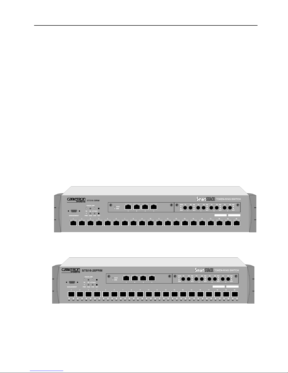
Figure 1. SmartStack STS16-20RM Token Ring Switch . . . . . . . 1
Figure 2. SmartStack STS16-20FRM Token Ring Switch . . . . . . 1
Figure 3. Location of LEDs, Switches, and Connectors
on STS16-20RM . . . . . . . . . . . . . . . . . . . . . . 5
Figure 4. Location of LEDs, Switches, and Connectors
on STS16-20FRM. . . . . . . . . . . . . . . . . . . . . . 5
Figure 5. The Back Panel . . . . . . . . . . . . . . . . . . . . . . . 10
Figure 6. Multiple Conversations Through a STS16-20RM or
STS16-20FRM Switch . . . . . . . . . . . . . . . . . . . 18
Figure 7. Typical Configuration with Switches
Using Multiple Bridging Modes . . . . . . . . . . . . . . . 20
Figure 8. A Switch Configured with Two VLANs . . . . . . . . . . . 30
Figure 9. Example of Dynamic Source Route Recovery, Base
Configuration . . . . . . . . . . . . . . . . . . . . . . . . 31
Figure 10. Example of Dynamic Source Route Recovery,
Normal State . . . . . . . . . . . . . . . . . . . . . . . . 32
Figure 11. Example of Dynamic Source Route Recovery,
Switch 1 Failed . . . . . . . . . . . . . . . . . . . . . . . 33
Figure 12. Typical LAN Segmentation . . . . . . . . . . . . . . . . . 48
Figure 13. A Simple Application of the Switch . . . . . . . . . . . . . 49
Figure 14. Typical Network without the SmartStack Switches . . . . . 50
Figure 15. Relieving the Overstressed Backbone . . . . . . . . . . . 50
Figure 16. Replacing SRBs with STS16-20RM or STS16-20FRM . . . 51
Figure 17. Star-Wired Topology of Interconnected Switches. . . . . . 52
Figure 18. Removing the SSIM Slot Cover . . . . . . . . . . . . . . . 56
Figure 19. Exposing the Rack Mounting Bracket. . . . . . . . . . . . 57
Figure 20. Mounting the Switch in a Rack or Cabinet . . . . . . . . . 58
Figure 21. Connecting Devices to Token Ring Ports . . . . . . . . . . 60
Figure 22. Connecting using Building Wiring . . . . . . . . . . . . . . 61
Figure 23. The Back Panel of the Switch. . . . . . . . . . . . . . . . 62
Figure 24. View of Console Connection—the MANAGEMENT port . . 66
Figure 25. Switch with Four VLANs . . . . . . . . . . . . . . . . . . 82
Figure 26. Setting up CrossLinks . . . . . . . . . . . . . . . . . . . 109
Figure 27. Primary and Traced DSRR Port . . . . . . . . . . . . . 141
Figure 28. TIA/EIA 232 Null-Modem Cable for the 25-pin Connector 229
Figure 29. TIA/EIA 232 Null-Modem Cable for the 9-pin Connector . 229
Figure 30. Straight-Through Cable . . . . . . . . . . . . . . . . . . 230
Figure 31. Data Connector-to-RJ-45 Straight-Through Cable . . . . 230
Notice

List of Tables
Table 1. Status LEDs and Their Meanings . . . . . . . . . . . . . . 8
Table 2. Stack-link LEDs and Their Meanings . . . . . . . . . . . . 9
Table 3. Port LEDs and Their Meanings . . . . . . . . . . . . . . . 9
Table 4. Back Panel Switches and Connectors. . . . . . . . . . . 10
Table 5. Capacity Specifications . . . . . . . . . . . . . . . . . . 13
Table 6. Performance Specifications . . . . . . . . . . . . . . . . 14
Table 7. Specifications of Physical Characteristics . . . . . . . . . 14
Table 8. Supported MIBs . . . . . . . . . . . . . . . . . . . . . . 34
Table 9. Supported RMON Groups . . . . . . . . . . . . . . . . . 36
Table 10. Console Configuration Settings . . . . . . . . . . . . . . 67
Table 11. Modem Settings . . . . . . . . . . . . . . . . . . . . . . 133
Table 12. Symptom, LED State and Recommended Procedure . . . 214
Table 13. Connecting to the Management Port . . . . . . . . . . . 227
Table 14. Pin-out of the Management Port. . . . . . . . . . . . . . 228
Table 15. Copper Cable Types. . . . . . . . . . . . . . . . . . . . 231
Table 16. Multimode Optical Fiber Cable Types . . . . . . . . . . . 231
Table 17. Lobe Length for 150 Ohm Shielded Media . . . . . . . . 233
Table 18. Lobe Lengths for 100 Ohm Shielded or Unshielded Cable 233
Table 19. Lobe Lengths for 100 or 120 Ohm
Shielded or Unshielded Cable . . . . . . . . . . . . . . . 234
Table 20. Lobe Lengths for Recommended Fiber Cable. . . . . . . 234
Table 21. Alternate Optical Fibers . . . . . . . . . . . . . . . . . . 234
xi
Notice

xii
Notice
1. Introduction
This chapter discusses switching technology and how the SmartStack STS1620RM and/or the STS16-20FRM Token Ring Switch can be used to improve
network performance. This chapter also includes a list of features and
specifications for the switch.
1
➽ Note:
STS16-20FRM.
The topics of this chapter are presented under the following titles:
•
•
•
The folloiwing figures display a front view of the STS16-20RM and the STS1620FRM Token Ring switches.
References to SmartStack STS16-20RM are also applicable to SmartStack
“Switching Technology”, starting on page 2.
“Front Panel Details” starting on page 5 and “Back Panel Details” starting on
page 10.
“Back Panel Details”, starting on page 10.
Figure 1. SmartStack STS16-20RM Token Ring Switch
Figure 2. Smar tStack STS16-20FRM Token Ring Switch
Introduction SmartStack STS16-20RM/STS16-20FRM Token Ring Switches, P/N: 9032957-01

2
Switching Technology
Demand for network bandwidth continues to grow, driven by the increasing
number of systems used in network-intensive applications. LAN segmentation has
been the prevalent method for addressing these demands and has been further
popularized by trends toward server centralization. However, the implementation
costs of LAN segmentation, as well as the real performance characteristics of
conventional network components, have served to limit growth of some Token
Ring networks. Alternative technologies for addressing bandwidth demands
present yet other inhibitors, usually relating to costs. Token Ring switching
provides users with an easy, cost-effective technique for addressing these demands.
Token Ring switches, such as the STS16-20RM and the STS16-20FRM, increase
throughput between Token Ring segments by supporting simultaneous, parallel
conversations. Switched connections between Token Ring segments last only for
the duration of the packet—new connections can be made between different
segments for the next packet.
Token Ring switches solve congestion problems caused by high-bandwidth devices
and powerful applications as well as the number of users. Therefore, each of these
devices—servers, for example—can be assigned its own 16 Mbps segment.
In Token Ring networks, the major bottleneck is typically the throughput to highbandwidth devices such as servers, and between routers, bridges, and switches. An
effective solution is full-duplex communication, an option for each segment
connected to a STS16-20RM or a STS16-20FRM port. Normally, Token Ring
operates in half-duplex communication mode, which means stations can either
receive or transmit. With full-duplex technology, two communicating stations can
transmit and receive at the same time. When packets can flow in both directions
simultaneously, effective Token Ring bandwidth doubles from 16 Mbps to 32 Mbps.
The STS16-20RM and the STS16-20FRM can forward Token Ring frames among
multiple, shared or dedicated Token Ring LAN segments. Using a frame
forwarding technique similar to that of a multiport Token Ring transparent bridge,
the switch uses Token Ring MAC addresses to forward Token Ring frames from
any of its ports to any other.
Switch of Switches
The STS16-20RM and the STS16-20FRM can be deployed in a variety of network
configurations, all of which provide a significant increase in network performance.
The series of Cabletron Token Ring products allows users to build network systems
that can transport data efficiently and scale upwards as throughput requirements
increase. The switches deliver high-reliability and media flexibility. These features
combine to allow the switches to be used as a switch of switches which provides
media flexibility in an Token Ring configuration.
SmartStack STS16-20RM/STS16-20FRM Token Ring Switches, P/N: 9032957-01 Introduction

The STS16-20RM and the STS16-20FRM can easily connect with other
SmartStack products to deliver a broad range of network carrying capacity.
Bandwidth is easily scaled to meet all performance requirements.
Switch of Servers
With client/server applications, many client workstations may attempt to access a
single server at the same time. This traffic pattern may create bottlenecks at the
server. To further enhance performance, the STS16-20RM and the STS16-20FRM
can deliver dedicated bandwidth to high-speed file servers. All servers perform
better with dedicated 16 Mbps bandwidth.
Even better performance can be achieved by installing multiple adapters in the
server. By connecting these adapters to the switch, multiple 16 Mbps paths to the
server are created, a solution that is only possible when using a switch.
The switch ties together all Token Ring devices lined to a local wiring center. In
networks, where a significant portion of the traffic moves locally between client
and server, the switch can be very effective.
3
Switch of Hubs
When network traffic increases beyond the capability of hubs, contention results.
Applications suffer and may even fail. The net effect of such a network
configuration is that all devices share a single 16 Mbps data path, thus reducing
overall network efficiency. The STS16-20RM and STS16-20FRM can be very
effective when used as a switch of hubs.
The switches can alleviate contention through microsegmentation, or reducing the
number of devices in each shared segment. To provide microsegmentation, the
switches divides a single 16 Mbps segment into multiple 16 Mbps segments. As an
example, a workgroup has 16 Mbps of capacity. The 20 ports on the switches
support 10 simultaneous conversations with 20 hubs, thus providing the workgroup
with 160 Mbps bandwidth throughput, which results in a significant gain in
bandwidth.
Switch of Desktops
The STS16-20RM and the STS16-20FRM are a cost-effective means of providing
dedicated bandwidth to individual desktop workstations. In this application, the
switch replaces a hub, providing excellent, hub-like network management
statistics. Total network capacity and throughput increase dramatically for attached
desktop workstations.
Introduction SmartStack STS16-20RM/STS16-20FRM Token Ring Switches, P/N: 9032957-01

4
Switch of Floors and Buildings
For network managers, multistory buildings and campuses can represent a unique
networking challenge. How can a network manager provide an efficient LAN
interconnect for users that are located on several floors of a building or in different
buildings?
Token Ring switching and the SmartStack product family can provide the best
solution. The STS16-20RM and the STS16-20FRM provide enhanced throughput
to local wiring closets that can be connected to a switch located in the data center.
Many networks consist of users located in different buildings of a campus
environment. The switches can be used as a collapsed backbone interconnecting
multiple buildings of a campus. They can provide the connectivity solution and
enhanced throughput that such campus environments require.
Switch of Routers
Router technology has had a significant impact on the design of today’s
internetworks. Routers have become the cornerstone of most production networks.
Although well equipped to provide firewall, WAN connectivity, security, and
connection between dissimilar LANs, routers are unable to provide high throughput
between desktop devices and servers. Because of these limitations, routers and
switches perform complimentary functions in the network.
The STS16-20RM and the STS16-20FRM can be used as a front-end to routers to
increase performance in each subnet. Communication between local clients and
servers is enhanced at the workgroup level below the router.
The switches can also be used to back-end routers. In networks were many routers
are interconnected over Token Ring and backbone performance is not acceptable,
the switches provide nonblocking communication between the routers for
enhanced network performance. This provides protocol transparency with
enhanced throughput in each subnet between local servers and desktops, thus
allowing network managers to build logical networks as large as network layer
protocol and broadcast traffic allow.
The Switched Port Analyzer also gives a collapsed backbone network superior
network management and the ability to perform protocol analysis from a single
location. The Switch Port Analyzer provides the latest technology for monitoring
switch-based networks and helps to reduce the cost of managing these networks.
SmartStack STS16-20RM/STS16-20FRM Token Ring Switches, P/N: 9032957-01 Introduction
Front Panel Details
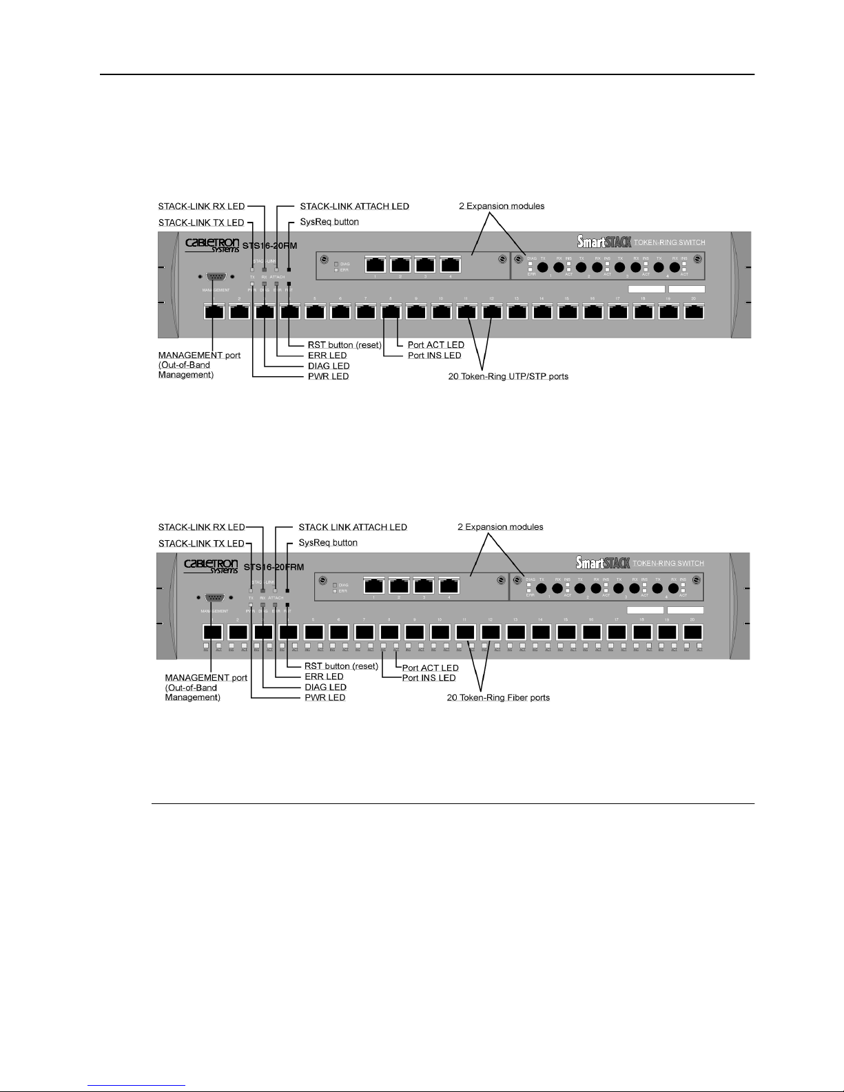
The front panel details of the switches are illustrated in Figure 3 and Figure 4. This
section lists all the connectors, controls, and LEDs of the front panel.
Figure 3. Location of LEDs, Switches, and Connectors
on STS16-20RM
5
Figure 4. Location of LEDs, Switches, and Connectors
on STS16-20FRM
The MANAGEMENT Po rt
The 9-pin, male, Out-of-Band Management (OBM) port labelled MANAGEMENT
functions as a DTE port.
This port enables attachment of a terminal, either local or remote, through a modem
connection. The terminal can be used to configure and monitor the switch.
The MANAGEMENT port automatically detects the baud rate of the terminal to
which it is attached.
Introduction SmartStack STS16-20RM/STS16-20FRM Token Ring Switches, P/N: 9032957-01

6
Token Ring Ports
STS16-20RM
•
Twenty shielded RJ-45 connectors for Token Ring connection.
— Support for the IBM Cabling System via 150 ohm, shielded twisted-pair
(150 ohm STP); or 100 or 120 ohm unshielded twisted-pair via Category
3, 4, or 5 cables.
— These ports allow half-duplex (HDX) or full-duplex (FDX) connections to
other switches, hubs, or end nodes.
— Ports 19 and 20 can attac to a MAU/CAU RI/RO port
STS16-20FRM
•
Twenty fiber VF-45 connectors for Token Ring connection.
— These ports allow half-duplex (HDX) or full-duplex (FDX) connections to
other switches, hubs, or end nodes.
— All 20 fiber ports can attach to a MAU/CAU RI/RO port.
— On STS16-20FRM, UTP/STP connections are only available by installing
an SSIM-T5-04 Token-Ring SmartStack Interface Module.
The switch will automatically sense what type of Token Ring connection is
•
being employed on each of its ports, whether it is a connection:
— to a shared-media segment via a Token Ring concentrator (Station mode)
— to another Token Ring switch
— operating at 4 Mbps or at 16 Mbps
— to a dedicated-media segment, directly to a Token Ring LAN station
operating in half-duplex or full-duplex mode (Port mode)
The switch will automatically configure (requiring no operator action) each port to
operate at the highest possible level of capability. No special crossover cables are
required for Token Ring stations on dedicated-media segments or for switch-toswitch connections; the same straight-through cabling is used regardless of the type
of connection. This auto-sense/auto-configure capability of the switch can be
overridden by explicit console management.
Switched Port Analyzer
Any of the Token Ring ports can be configured as an analyzer port. An analyzer
port is used to monitor any of the other ports in the same physical switch. The
activity can then be traced by a Token-Ring network analyzer attached to the
analyzer port.
SmartStack STS16-20RM/STS16-20FRM Token Ring Switches, P/N: 9032957-01 Introduction

SmartStack Interface Modules
The switch contains two SmartStack interface slots (see Figure 3 or Figure 4) that
will accommodate optional, field-installable SmartStack Interface Modules that
provide additional connections. Future SmartStack Interface Modules will provide
the following types of connections:
SSIM-T5-04 4-Port Token-Ring UTP/STP
•
SSIM-T8-04 4-Port Token-Ring Fiber
•
SSIM-A2-01 ATM155 LANE Bridge UTP
•
SSIM-A8-01 ATM155 LANE Bridge MMF
•
SSIM-R2-02 High-Speed Token Ring UTP
•
SSIM-R8-02 High-Speed Token Ring MMF
•
SSIM-H2-02 Fast Ethernet UTPs
•
7
Reset But t o n
The switch has a recessed reset button labelled RST that is located on the front
panel. Pressing the reset button resets the hardware and software and clears all
tables and memory, including the address tables. Pressing the reset button does not
clear the values stored in nonvolatile random access memory (NVRAM).
System Req uest Button
This unlabeled recessed button is located on the front panel above the reset button.
Pressing the button causes the
device attached to the MANAGEMENT port. Pressing the button for more than
five seconds will initiate a modem download of the main image.
➽ Note:
personnel. The button is recessed to prevent accidental activation.
Labels
The two labels in the right side of the front panel are:
System Request
The system request button should be used only at the direction of service
menu to appear on the console
The MAC Address Label:
•
The unique globally assigned base Base MAC-Address of the switch.
The Switch Number Label:
•
Blank label for an individual user identification of the switch.
Introduction SmartStack STS16-20RM/STS16-20FRM Token Ring Switches, P/N: 9032957-01

8
Status and Activity LEDs
The switch features three status LEDs at the left on the front panel that show the
current status of the switch. There are also three activity LEDs at the left that
indicate the activity of the optional stacker link module. Moreover, each Token
Ring port has two LEDs. On STS16-20RM, these two LEDs are unlabeled and
located on the upper edge of each port. On STS16-20FRM, these LEDs are located
under each port and labeled ACT and INS.
Refer to Figure 3 and Figure 4 in this chapter for the locations of all the LEDs.
Table 1 lists the status LEDs and their meanings.
LED State Meaning
PWR
DIAG
ERR
Off
On
On
Blinking
On
The switch is not connected to a power outlet, or
the power supply is faulty.
The switch is receiving power.
The DIAG diagnostics LED is on during the
power-on self-test.
During download of a new software image, the
DIAG LED blinks to indicate the clearing (slow
blink) and loading (faster blink) of FLASH
memory.
The ERR LED is off during normal operation. If
the LED turns on, an error has occurred. Power
the switch down and up again. The ERR LED
should not turn on again. If it does, the switch is
faulty.
Note that the ERR LED also turns on if the switch
is powered only by an external power supply.
Table 1. Status LEDs and Their Meanings
The stack-link LEDs and port LEDs are described in the tables on the next page.
SmartStack STS16-20RM/STS16-20FRM Token Ring Switches, P/N: 9032957-01 Introduction

Table 2 lists the stack-link LEDs and their meanings.
LED State Meaning
9
TX
On
or
Data is being transmitted to the stack link.
blinking
RX
On
or
Data is being received from the stack link.
blinking
AT TA CH
Table 2. Stack-link LEDs and Their Meanings
On
A connection has been established to the stack.
Table 3 lists the port LEDs and their meanings.
LED State Meaning
INS
On
The Token Ring port is inserted into the ring.
(left LED of
port)
Off
Blinking
The Token Ring port is not inserted into the ring.
The Token Ring port is disabled.
ACT
(right LED of
or
On
blinking
Data is being transmitted to or received from the
port.
port)
Table 3. Port LEDs and Their Meanings
Introduction SmartStack STS16-20RM/STS16-20FRM Token Ring Switches, P/N: 9032957-01

10
Back Panel Details
The back panel of the switches are illustrated in Figure 5.
Figure 5. The Back Panel
Table 4 lists the back panel connectors on the switch.
Name Description
AC connection Standard AC power connection.
Redundant power
Connector for the optional redundant power supply unit.
supply
Table 4. Back Panel Switches and Connectors
SmartStack STS16-20RM/STS16-20FRM Token Ring Switches, P/N: 9032957-01 Introduction

Features and Specifications
Features and specifications for the STS16-20RM and the STS16-20FRM are listed
below.
Features
Performance and Advanced Features
Three switching modes:
•
— Low latency cut-through
— Store and forward
— Auto (Adaptive cut-through)
Enhanced bridging modes:
•
11
— Transparent bridging
— Source route switching
— Source route bridging (SRB)
— Source route transparent bridging (SRT)
Support for duplicate MAC address schemes
•
Automatic port sensing of operating mode and media speed
•
Multiple Token Ring port operation modes:
•
— Half-duplex concentrator and station
— Full-duplex concentrator and station (Dedicated Token Ring)
— RI/RO-like connection
Spanning Tree Protocol support:
•
— IEEE 802.1D
— IBM Spanning Tree Protocol
CrossLink high-speed inter-switch connection
•
(up to 256 Mbps using eight ports)
Advanced filtering (MAC address / Protocol)
•
VLAN (Virtual LAN) support
•
Support for transmission priorities
•
Congestion control
•
Introduction SmartStack STS16-20RM/STS16-20FRM Token Ring Switches, P/N: 9032957-01

12
SRB Redundancy
•
Support for ClearSession high availability features
•
Management
Extensive and sophisticated network management:
•
— SNMP management
— Out-of-band management via Telnet and VT100 consoles
— Graphical management application for Windows 95 and Windows NT (for
information on additional management applications for Unix, please
contact your local sales representative)
Support for RMON and standard MIBs
•
Network statistics
•
LAN probe port mirroring
•
Fault isolation and detection
•
Download via TFTP or X-modem of new switch microcode
•
Up- and download of switch configuration via TFTP
•
Scalability and High Availability
Up to 5,500 active LAN stations per group of four ports (1-4, 5-8, 9-12,
•
13-16, 17-20) with a maximum of 10,000 active LAN stations per switch
Stackable architecture
•
Optional redundant power supply
•
Six switches can receive backup power from one SmartStack STS-RPC
Redundant Power Centre equipped with six SmartStack STS_PSU Redundant
Power Supply Unit.
High density switch with seamless integration of LAN & ATM via LAN
•
emulation bridging
Installation
No special crossover cable required
•
Rack or surface mounting
•
Plug and Play for transparent forwarding:
•
— Automatic learning of network configuration
— Transparent to high-level protocol
Automatic sensing and configuration of ports
•
SmartStack STS16-20RM/STS16-20FRM Token Ring Switches, P/N: 9032957-01 Introduction

A factory-assigned MAC address (the switch can also be configured with a
•
locally administered MAC address)
Specifications
The tables on the following pages list the product specifications for the STS1620RM and the STS16-20FRM.
Capacity
Specification Value
13
Number of Token Ring ports
(base configuration)
Maximum number of
additional Token Ring ports in
expansion modules
Number of Token Ring switches
in stack
2 Expansion slots, choice of
Global lookup table size
(stations and bridges)
20
8
8 using the SmartStack STS-8SU Stacker
Unit
5 using the SmartStack STS-5SU Stacker
Unit
2 using the SmartStack STS-LM Link
Module
4 x 4/16 Mbps RJ-45 Token Ring
4 x 4/16 Mbps Fiber Token Ring
1 x ATM155 Card (UTP and MMF)
2 x High-Speed Token Ring (UTP and Fiber)
10,000
Local lookup table size, total for
4 ports
(stations and bridges)
Maximum number
of logical rings
Maximum number of VLANs
Table 5. Capacity Specifications
Introduction SmartStack STS16-20RM/STS16-20FRM Token Ring Switches, P/N: 9032957-01
5,500
63
63

14
Performance
Specification Value
Maximum frame rate per port
Maximum aggregate frame rate
per 4 ports
Throughput per port
Aggregate switching rate
(unicast or broadcast) for entire
switch
Within switch latency
(cut-through)
Table 6. Performance Specifications
Physical Characteristics
Specification Value
57,000 pps in each direction (measured with a
frame size of 19 bytes)
200,000 pps in each direction. Full media
speed for frame sizes above 28 bytes
16 Mbps in each direction for all frame sizes
1,500,000 pps for smallest frame sizes
35 µs
Rack mount
Dimensions
Weight
Power
Frequency
AC current rating
Thermal dissipation
(without modules)
MTBF
19" rack mount (hardware included)
Width: 19" (48.3 cm)
Depth: 15.74" (40.0 cm)
Height 3.46" (8.80 cm)
19.4 lbs. (8.8 Kg)
100 to 240 VAC autosensing
50/60 Hz
1.5 A @ 100 V; 0.75 A @ 220 V
STS16-20RM:
STS16-20FRM
90 W, 307 BTU/h
: 80 W, 273 BTU/h
STS16-20RM: 77,240 hours
STS16-20FRM: 40,342 hours
Calculated using Bellcore TR-332, issue 6
Table 7. Specifications of Physical Characteristics
SmartStack STS16-20RM/STS16-20FRM Token Ring Switches, P/N: 9032957-01 Introduction

Specification Value
15
Operating Temperature:
Non-operating Temperature:
Humidity:
Operating
Non-operating
Electromagnetic compatibility
immunity
Electromagnetic compatibility
emission
Safety
10 to 40°C (50 to 104°F)
-10 to 70°C (13 to 158°F)
8 to 80% (non-condensing)
90% @ 45°C (113°F)
EN 50082-1
EN 61000-3-2
EN 61000-3-3
FCC Part 15, subpart b, Class A
EN55022 Class A
CISPR 22 Class A
IEC 950
UL1950
CSA C22.2 No. 950
EN60950
MANAGEMENT port
Software updates
Protocol compatibility
Spanning Tree Protocol
support
MIBs supported
TIA/EIA-232-F, DB9 male connector
Flash PROM, TFTP, X-modem
Transparent to higher layer protocols
IEEE 802.1D compliant
IBM Spanning Tree
SNMP MIB II (RFC1213)
SR Bridge MIB (RFC1525)
Bridge MIB (RFC1493)
Evolution of the Interfaces Group of MIB-II
(RFC1573)
RMON MIB/TR extensions - selected
groups only (RFC1757/1513)
IEEE 802.5 MIB (RFC1749/1748)
IEEE 802.5r DTR MIB
IEEE 802.5r DTR MAC MIB
STS16-20RM MIB
VTP MIB
Table 7. Specifications of Physical Characteristics
Introduction SmartStack STS16-20RM/STS16-20FRM Token Ring Switches, P/N: 9032957-01

16
Specification Value
Network management
Table 7. Specifications of Physical Characteristics
SNMP Management Platform
-
Console
-
Telnet sessions
-
SmartStack Manager for Windows 95
-
and NT
Additional management applications
-
available on Unix platforms:
—Tivoli TME 10 NetView for AIX
❏
SmartStack STS16-20RM/STS16-20FRM Token Ring Switches, P/N: 9032957-01 Introduction
 Loading...