

Cabletron Systems SmartSTACK ELS100-S24TX2M, SmartSTACK ELS-S1DC Quick Installation Manual
SmartSTACK FAST ETHERNET SWITCH
SINGLE DC REDUNDANT POWER
SUPPLY UNIT
Cabletron System's ELS-S1DC Redundant Power
Supply Unit (RPU) can supply 150 Watts of backup
power to a single Cabletron System's SmartSTACK
ELS100-S24TX2M switch in the event of an AC loss or
failure of an internal power supply. Please check with
Cabletron Systems for information on the devices
supported by this RPU.
Features and Benefits
• Supports one Cabletron System's SmartSTACK
ELS100-S24TX2M switch
• AC line cord can draw power from a different supply
circuit
• DC line cord provides backup power to the attached
device
Front and Rear Panels
A Power indicator is located on the RPU’s front panel.
While the AC supply and DC backup receptacles are
located on the RPU’s rear panel.
The Power LED can be used to verify if this unit is
functioning properly. The following table details the
indicator function provided by the ELS-S1DC:
Status LEDs
LED Condition Status
Power On Unit is receiving power.
INSTALLING THE RPU
The RPU may be placed on a desktop or mounted in a
rack.
Warning: DO NOT install this RPU anywhere it may
come in contact with water (i.e. floor) Cabletron
recommends that this RPU be installed in a network
rack.
Equipment Checklist
After unpacking the RPU, check the contents of the box
to be sure you’ve received the following items:
• Redundant Power Supply Unit — provides backup
power to one Cabletron System's device
• One AC Supply Power Cord — US, Continental
Europe or UK
• One DC Backup Power Cord — with D-sub
connectors on both ends
• Four Self-adhesive Rubber Feet
• Rack Mounting Kit — brackets and screws
• Star-head screwdriver
• Quick Installation Guide
Desktop or Rack Mounting
You can set the RPU on a desktop or flat surface near
a separate AC power source and close to the device to
which it is to supply power. Make sure that the
mounting surface can safely support the RPU device
and that there is adequate space around the RPU for
ventilation and cooling.
The ELS-S1DC RPU ships with four (4) rubber feet.
Stick the self-adhesive rubber foot pads on each of the
four concave spaces located on the bottom of the RPU.
The rubber foot pads cushion the RPU against shock/
vibrations and provide space between each device for
ventilation.
To mount the RPU in a standard EIA 19-inch rack, use
the brackets and screws supplied with the RPU. Use a
cross-head screwdriver to attach the brackets to the
side of the RPU. Position the RPU in the rack by lining
up the holes in the brackets with the appropriate holes
on the rack. And then use the supplied screws to mount
the RPU in the rack. (Leave about two inches of space
at the rear of the RPU to ensure adequate ventilation.)
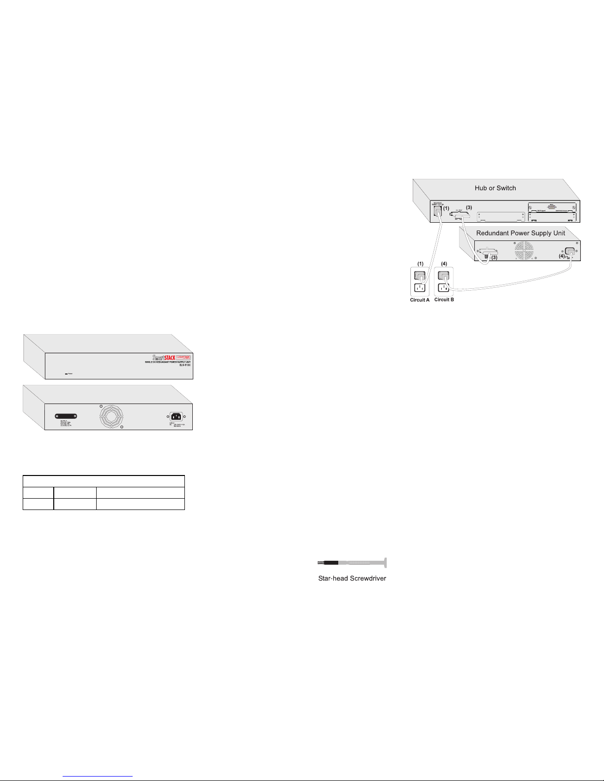
Making Connections
Caution: DO NOT connect the RPU to an AC power
source until the DC power cord has been connected to
the other device (hub or switch).
1. Connect one end of the AC cord to the AC
receptacle on the supported device (hub or switch),
and the other end to a grounded power outlet.
2. Use the provided star-head screwdriver to loosen
the faceplate screws on the RPU’s output
receptacle and remove the faceplates from both the
RPU and the supported device (hub or switch).
3. Connect one end of the DC cord to the redundant
power receptacle on the other device (hub or
switch), and the other end to the output receptacle
on the RPU.
4. Connect one end of the AC cord to the AC
receptacle on the RPU, and the other end to a
grounded power outlet. The Power LED on the
RPU should light up.
TROUBLESHOOTING
If you experience any problems with the RPU, check
the following items before contacting Cabletron
Systems Technical Support:
• Ensure that the RPU in the stack is powered up.
• Ensure that the devices attached to the stack are
powered up and operating correctly.
• Check the connectors on both ends of the power
cable to be sure they are properly engaged. Tighten
the screws on the cable connectors to ensure a
good connection.

SPECIFICATIONS
Receptacle
IEC Socket
Size
12.99 x 5.12 x 2.48 in. (33 x 13 x 6.3 cm)
Weight
7.39 lb. (3.35 kg)
Temperature
Operating: 32° to 131°F (0° to 55°C)
Storage: -40° to 185°F (-40° to +85°C)
Relative Humidity
20% to 90%
Cooling
1 fan on rear
AC Input Power
100 - 240V ~ 5A, 50/60Hz
DC Output Power
+ 3.3 VDC @ 30 A max.,
+ 5 VDC @ 9 A max.,
+ 12 VDC @ 0.7 A max.
DC Power Cable Connector
22-pin
Overload Protection
Reduces output to safe levels when output exceeds 120%
MTBF
50,000 hours minimum
Regulatory Compliances
Safety
UL 1950, CSA C22.2 No. 950, 73/23/EEC, EN 60950,
IEC 950
Electromagnetic Compatibility (EMC)
FCC Part 15, CSA C108.8, 89/336/EEC, EN 55022,
EN 61000-3-2, EN 61000-3-3, EN 50082-1,
AS/NZS 3548, VCCI V-3
Warranty
Three years
SmartSTACK
REDUNDANT POWER
ELS-S1DC
QUICK INSTALLATION GUIDE
9033267-01
E1299-R01
150210-102
NOTICE
Cabletron Systems reserves the right to make changes in specifications and other
information contained in this document without prior notice. The reader should in
all cases consult Cabletron Systems to determine whether any such changes have
been made.
The hardware, firmware, or software described in this manual is subject to change
without notice.
IN NO EVENT SHALL CABLETRON SYSTEMS BE LIABLE FOR ANY
INCIDENTAL, INDIRECT, SPECIAL, OR CONSEQUENTIAL DAMAGES
WHATSOEVER (INCLUDING BUT NOT LIMITED TO LOST PROFITS)
ARISING OUT OF OR RELATED TO THIS MANUAL OR THE INFORMATION CONTAINED IN IT, EVEN IF CABLETRON SYSTEMS HAS BEEN
ADVISED OF, KNOWN, OR SHOULD HAVE KNOWN, THE POSSIBILITY OF
SUCH DAMAGES.
1999 by Cabletron Systems, Inc., P .O. Box 5005, Rochester, NH 03866-5005
All Rights Reserved
Printed in Taiwan, R.O.C.
Order Number: 9033267-01 May 2002
Cabletron, Cabletron Systems, and SmartSTACK are trademarks or registered
trademarks of Cabletron Systems, Inc.
All other product names mentioned in this manual may be trademarks or registered
trademarks of their respective companies.
FCC NOTICE
This device complies with Part 15 of the FCC rules. Operation is subject to the
following two conditions: (1) this device may not cause harmful interference, and
(2) this device must accept any interference received, including interference that
may cause undesired operation.
NOTE: This equipment has been tested and found to comply with the limits for a
Class B digital device, pursuant to Part 15 of the FCC rules. These limits are
designed to provide reasonable protection against harmful interference when the
equipment is operated in a commercial environment. This equipment uses,
generates, and can radiate radio frequency energy and if not installed in accordance
with the operator’s manual, may cause harmful interference to radio communications. Operation of this equipment in a residential area is likely to cause interference in which case the user will be required to correct the interference at his own
expense.
WARNING: Changes or modifications made to this device which are not
expressly approved by the party responsible for compliance could void the user’s
authority to operate the equipment.
INDUSTRY CANADA NOTICE
THIS CLASS B DIGITAL APPARATUS COMPLIES WITH CANADIAN
ICES-003.
CET APPAREIL NUMERIQUE DE LA CLASSE B EST CONFORME A LA
NORME NMB-003 DU CANADA.
VCCI NOTICE
EC CONFORMANCE DECLARATION
European contact: Cabletron Systems Limited
Nexus House, Newbury Business Park
London Road, Newbury
Berkshire RG13 2PZ, England
This information technology product complies with ISO/IEC Guide 22 and
EN45014. It conforms to the following specifications:
EN55022(1988)/CISPR-22(1985) Class B
EN50082-1: IEC 1000-4-2, 3, 4, 6
This information technology product complies with the requirements
of the Low Voltage Directive 73/23/EEC and the EMC Directive 89/
336/EEC and carries the CE Mark accordingly.
Only qualified personnel should perform installation
procedures.
 Loading...