

Cabletron Systems SmartSTACK ELS10-27TX Supplement Manual
SmartSTACK ETHERNET
ELS10-27TX SUPPLEMENT
ETHERNET SWITCH
ELS10-27TX
RESET
COM
PWR
CPU
PORT STATUS MODE
STATUS
TX ACT FDX MON
RX COL 100 USR
LINK
LINK
LINK
LINK
LINK
LINK
LINK
LINK
LINK
LINK
STATUS
STATUS
STATUS
STATUS
STATUS
STATUS
STATUS
STATUS
2X 4X 6X 8X 10X 12X 14X 16X 18X 20X 22X 24X
LINK
STATUS
STATUS
STATUS
LINK
10BASE-T/100BASE-TX
STATUS
LINK
25X 26X 27X
EPIM100
LINK
LINK
STATUS
STATUS
26
STATUS
27
9033517


Only qualified personnel should perform installation
procedures.
NOTICE
Cabletron Systems reserves the right to make cha nges in specifications and othe r info rm at ion
contained in this document without prior notice. The reader shoul d in all cases consult Cabletron
Systems to determine whet he r any such changes have been made.
The hardware, firm wa re, or software described in thi s ma nual is subject to change wit hout notice.
IN NO EVENT SHALL CABLETRON SYSTEMS BE LIABLE FOR ANY INCIDENTAL,
INDIRECT, SPECIAL, OR CONSEQUENTIAL DAMAGES WHATSOEVER (INCLUDING BUT
NOT LIMITED TO LOST PROFITS) ARISING OUT OF OR RELATED TO THIS MANUAL OR
THE INFORMATION CONTAINED IN IT, EVEN IF CABLETRON SYSTEMS HAS BEEN
ADVISED OF, KNOWN, OR SHOULD HAVE KNOWN, THE POSSIBILITY OF SUCH
DAMAGES.
Cabletron Systems, Inc.
35 Industrial Way
Rochester, NH 03867
2000 by Cabletron Systems, Inc.
All Rights Reserved
Printed in the United States of America
Order Number: 9033517 May 2000
Cabletron Systems is a registered trademark: Smar tSTA CK and ELS10-27TX are trademarks of
Cabletron Systems, Inc.
All other product names ment ioned in this manu al may be tradem arks or registere d trademarks of
their respective companies.
i

Notice
FCC NOTICE
This device complies with Part 15 of the FCC rules. Operation is subject to t he following two
conditions: (1) this device may not cause harm ful interference, and (2) this device must ac ce pt any
interference received, includi ng i nterference that ma y cause undesired operation.
NOTE: This equipment has been tested and found to comply with the limits for a Class A digital
device, pursuant t o Part 15 of the FCC rules. These limi ts are designed to provide reasonable
protection against harmful interference when the equipment is operated in a commercial environment.
This equipment uses, generates, and can radiate radio frequency energy and i f n ot installed in
accordance with the operator’s manual, may cause harmful interferenc e to radio communica tions.
Operation of this equipment in a residential area is likely to cause interference in which case the user
will be required to correct the interfer ence at his own expense.
WARNING: Changes or modifications made to this device which are not expressly approved by the
party responsible for compliance could void the user’s authority to operate th e equipment.
INDUSTRY CANADA NOTICE
This digital appa ratus does not exceed the Class A limits for radio noise emissions from dig it al
apparatus set out in the Radio Interferenc e Regulations of the Canad ia n Department of
Communica ti ons.
Le présent appareil numérique n’émet pas de bruits radioélectriques dépassant les limites applicables
aux appareils numé ri que s de la cl ass A prescrites dans le Règlement sur le brouillage radioélec tri que
édicté par le min ist ère des Communications du Canada.
VCCI NOTICE
This is a Class A product base d on the standard of the Voluntary Co nt rol Council for Interference by
Information Technology Equipment (VCCI). If this equipm ent is used in a domesti c environment,
radio disturbance ma y ari s e. When such trouble occurs, the user may be requi red to take corrective
actions.
ii

Notice
CABLETRON SYSTEMS, INC.
PROGRAM LICENSE AGREEMENT
IMPORTANT : THIS LICENSE APPLIES FOR USE OF PRODUCT IN THE FOLLOWING
GEOGRAPHICAL REGIONS:
CANADA
MEXICO
CENTRAL AMERICA
SOUTH AMERICA
BEFORE OPENING OR UTILIZING THE ENCLOSED PRODUCT,
CAREFULLY READ THIS LICENSE AGREEMENT.
This document is an a gre ement (“Agreement”) between You, the end user, and Cabletron Systems,
Inc. (“Cabletron ”) that sets forth your rights and obligations with respect to the Cablet ron software
program (“Program”) in the package. The Program may be contained in firmware, chips or other
media. UTILIZING THE ENCLOSED PRODUCT, YOU ARE AGREEING TO BECOME BOUND
BY THE TERMS OF THIS AGREEMENT, WHICH INCLUDES THE LICENSE AND THE
LIMITATION OF WARRANTY AND DISCLAIMER OF LIABILITY. IF YOU DO NOT AGREE
TO THE TERMS OF THIS AGREEMENT, RETURN THE UNOPENED PRODUCT TO
CABLETRON OR YOUR DEALER, IF ANY, WITHIN TEN (10) DA YS FOLLOWING THE DA TE
OF RECEIPT FOR A FULL REFUND.
IF YOU HAVE ANY QUESTIONS ABOUT THIS AGREEMENT, CONTACT CAB LETRON
SYSTEMS +1-603-332-9400. Attn: Legal Department.
1. LICENSE. You have the right to use only th e one (1) copy of the Program provided in this
package subj ec t to the terms and conditions of this License Agreem ent.
You may not copy, reproduce or transmit any part of the Program e xc ept as permitted by the
Copyright Act of th e Uni te d Sta t es or as authorized in writ ing by Cabletron.
2. OTHER RESTRICT ION S. You may not reve rse engineer, decomp il e , or di sasse mble the
Program.
3. APPLICABLE LAW. This License Agreement shall be in terpreted and governe d under the
laws and in th e s ta te and federal courts of New Hamps hire. You acce pt the personal juris diction and
venue of the New Hampshi re courts.
4. EXPORT REQUIREMENTS. You understand that Cabletron and its Affiliates are subject to
regulation by ag encies of the U.S. Governme nt, including the U.S. Depart m ent of Commerce, which
prohibit export or diversion of certain technical products to certain countries, unless a license to export
the product is obtained from the U.S. Government or an exception from obtaining such license may be
relied upon by the exporting party.
If the Program is exported from the United States pursuant to the License Exception CIV under
the U.S. Export Admi ni s tra ti on Regulations, You agree that You are a civil end user of t he Program
and agree that You will use the Program for civil end us es onl y and not for military purp ose s.
iii

Notice
If the Program is exported from the United States pursuant to the License Exception TSR under
the U.S. Export Admi ni s tra ti on Regulations, in addition to the restricti on on transfer set forth in
Sections 1 or 2 of thi s A gre ement, You agree not to (i ) ree xport or release th e Program, the source
code for the Program or technology to a national of a country in Country Groups D:1 or E:2 (Albania,
Armenia, Azerbaij an, Belarus, Bulgari a, Ca mbodia, Cuba, Estonia, Georgia, Iraq, Kazakhsta n,
Kyrgyzstan, Laos, Latvia, Libya , Lithuania, Moldova, North Kor ea, t he Peopl e ’s Republic of Chin a,
Romania, Russia, Rwa nda, Tajikistan, Turkmenistan, Ukra ine, Uzbekistan, Vietnam, or such other
countries as may be designated by the United States Government), (ii) export to Country Groups D:1
or E:2 (as defined herein) the direct product of the Program or the technology, if such foreign
produced direct product is subject to national security control s as ide nt ifi ed on the U.S. Commerce
Control List, or (iii ) if the direct product of th e t ec hnology is a complete plan t o r a ny m aj or
component of a pl ant, export to Country Groups D:1 or E:2 the direct product of the pl ant or a major
component thereof, if such foreign produc ed direct product is subje ct to na tional security cont rols as
identified on t he U.S. Com m erce Control List or is subje c t to State Department controls under the
U.S. Munitions List.
5. UNITED STATES GOV ERNME NT RESTRICTED RIGHTS. The enclosed Prod uc t (i )
was developed sole ly at private expense; (ii) contains “restricted computer software” submitted with
restricted rights in accordance with section 52.227- 19 (a) through (d) of the C om mercial Computer
Software-Restricted Rig hts Clause and its successors, and (i ii ) in all respects is proprietary data
belonging to Cabletron and/or its suppliers. For Department of Defense units, the Product is considered
commercial computer software in accordance with DFARS section 227.7202-3 and its successors, and
use, duplication, or disclosure by the Government is subje c t to restrictions set forth herein.
6. EXCLUSION OF WA RRANTY. E x ce pt as may be speci f ic ally provided by C abletron in
writing, Cabletron makes no warranty, expressed or implied, concerning the Program (including its
documentation and media).
CABLETRON DISCLAIMS ALL WARRANTIES, OTHER THAN THOSE SUPPLIED TO
YOU BY CABLETRON IN WRITING, EITHER EXPRESS OR IMPLIED, INCLUDING BUT
NOT LIMITED TO IMPLIED WARRANTIES OF MERCHANTABILITY AND FITNESS FOR A
PARTICULAR PURPOSE, WITH RESPECT TO THE PROGRAM, THE ACCOMPANYING
WRITTEN MATERIALS, AND ANY ACCOMPANYING HARDWARE.
7. NO LIABILITY FOR CONSEQU ENT IAL DAM AGES. IN NO EVENT SHALL
CABLETRON OR ITS SUPPLIERS BE LIABLE FOR ANY DAMAGES WHATSOEVER
(INCLUDING, WITHOUT LIMITATION, DAMAGES FOR LOSS OF BUSINESS, PROFITS,
BUSINESS INTERRUPTION, LOSS OF BUSINESS INFORMATION, SPECIAL, INCIDENTAL,
CONSEQUENTIAL, OR RELIANCE DAMAGES, OR OTHER LOSS) ARISING OUT OF THE
USE OR INABILITY TO USE THIS CABLETRON PRODUCT, EVEN IF CABLETRON HAS
BEEN ADVISED OF THE POSSIBILITY OF SUCH DAMAGES. BECAUSE SOME STATES DO
NOT ALLOW THE EXCLUSION OR LIMITATION OF LIABILITY FOR CONSEQUENTIAL OR
INCIDENTAL DAMAGES, OR IN THE DURATION OR LIMITATION OF IMPLIED
WARRANTIES IN SOME INSTANCES, THE ABOVE LIMITATION AND EXCLUSIONS MAY
NOT APPLY TO YOU.
iv

Notice
CABLETRON SYSTEMS SALES AND SERVICE, INC.
PROGRAM LICENSE AGREEMENT
IMPORTANT: THIS LICENSE APPLIES FOR USE OF PRODUCT IN THE UNITED
STATES OF AMERICA AND BY UNITED STAT ES OF AMERICA
GOVERNMENT END USERS.
BEFORE OPENING OR UTILIZING THE ENCLOSED PRODUCT,
CAREFULLY READ THIS LICENSE AGREEMENT.
This document is an a gre ement (“Agreement”) between You, the end user, and Cabletron Systems
Sales and Service, In c. (“Cabletron”) that sets forth your rights and obli gations with respect to the
Cabletron software program (“Program”) in the package. The Program may be contained in firmware,
chips or other media. UTILIZING THE ENCLOSED PRODUCT, YOU ARE AGREEING TO
BECOME BOUND BY THE TERMS OF THIS AGREEMENT, WHICH INCLUDES THE
LICENSE AND THE LIMITATION OF WARRANTY AND DISCLAIMER OF LIABILITY. IF
YOU DO NOT AGREE TO THE TERMS OF THIS AGREEMENT, RETURN THE UNOPENED
PRODUCT TO CABLETRON OR YOUR DEALER, IF ANY, WITHIN TEN (10) DAYS
FOLLOWING THE DATE OF RECEIPT FOR A FULL REFUND.
IF YOU HAVE ANY QUESTIONS ABOUT THIS AGREEMENT, CONTACT CAB LETRON
SYSTEMS +1-603-332-9400. Attn: Legal Department.
1. LICENSE. You have the right to use onl y the one (1) copy of the Program provided in this
package subj ec t to the terms and conditions of this License Agreem ent.
You may not copy, reproduce or transmit any part of the Program e xc ept as permitted by the
Copyright Act of th e Uni te d Sta t es or as authorized in writ ing by Cabletron.
2. OTHER RESTRICT ION S. You may not reverse engineer, decompile, or disassembl e the
Program.
3. APPLICABLE LAW. Thi s Lic e nse Agreement shall be in te rpreted and governed under the
laws and in th e s ta te and federal courts of New Hamps hire. You acce pt the personal juris diction and
venue of the New Hampshi re courts.
4. EXPORT REQUIREMENTS. You understand that Cabletron and its Affiliates are subject to
regulation by ag encies of the U.S. Governme nt, including the U.S. Depart m ent of Commerce, which
prohibit export or diversion of certain technical products to certain countries, unless a license to export
the product is obtained from the U.S. Government or an exception from obtaining such license may be
relied upon by the exporting party.
If the Program is exported from the United States pursuant to the License Exception CIV under
the U.S. Export Admi ni s tra ti on Regulations, You agree that You are a civil end user of t he Program
and agree that You will use the Program for civil end us es onl y and not for military purp ose s.
v

Notice
If the Program is exported from the United States pursuant to the License Exception TSR under
the U.S. Export Admi ni s tra ti on Regulations, in addition to the restricti on on transfer set forth in
Sections 1 or 2 of thi s A gre ement, You agree not to (i ) ree xport or release th e Program, the source
code for the Program or technology to a national of a country in Country Groups D:1 or E:2 (Albania,
Armenia, Azerbaij an, Belarus, Bulgari a, Ca mbodia, Cuba, Estonia, Georgia, Iraq, Kazakhsta n,
Kyrgyzstan, Laos, Latvia, Libya , Lithuania, Moldova, North Kor ea, t he Peopl e ’s Republic of Chin a,
Romania, Russia, Rwa nda, Tajikistan, Turkmenistan, Ukra ine, Uzbekistan, Vietnam, or such other
countries as may be designated by the United States Government), (ii) export to Country Groups D:1
or E:2 (as defined herein) the direct product of the Program or the technology, if such foreign
produced direct product is subject to national security control s as ide nt ifi ed on the U.S. Commerce
Control List, or (iii ) if the direct product of th e t ec hnology is a complete plan t o r a ny m aj or
component of a pl ant, export to Country Groups D:1 or E:2 the direct product of the pl ant or a major
component thereof, if such foreign produc ed direct product is subje ct to na tional security cont rols as
identified on t he U.S. Com m erce Control List or is subje c t to State Department controls under the
U.S. Munitions List.
5. UNITED STATES GOV ERNME NT RESTRICTED RIGHTS. The enclosed Prod uc t (i )
was developed sole ly at private expense; (ii) contains “restricted computer software” submitted with
restricted rights in accordance with section 52.227- 19 (a) through (d) of the C om mercial Computer
Software-Restricted Rig hts Clause and its successors, and (i ii ) in all respects is proprietary data
belonging to Cabletron and/or its suppliers. For Department of Defense units, the Product is considered
commercial computer software in accordance with DFARS section 227.7202-3 and its successors, and
use, duplication, or disclosure by the Government is subje c t to restrictions set forth herein.
6. EXCLUSION OF WA RRANTY. Except as may be specifically provided by Cabletron in
writing, Cabletron makes no warranty, expressed or implied, concerning the Program (including its
documentation and media).
CABLETRON DISCLAIMS ALL WARRANTIES, OTHER THAN THOSE SUPPLIED TO
YOU BY CABLETRON IN WRITING, EITHER EXPRESS OR IMPLIED, INCLUDING BUT
NOT LIMITED TO IMPLIED WARRANTIES OF MERCHANTABILITY AND FITNESS FOR A
PARTICULAR PURPOSE, WITH RESPECT TO THE PROGRAM, THE ACCOMPANYING
WRITTEN MATERIALS, AND ANY ACCOMPANYING HARDWARE.
7. NO LIABILITY FOR CONSEQU ENT IAL DAM AGES. IN NO EVENT SHALL
CABLETRON OR ITS SUPPLIERS BE LIABLE FOR ANY DAMAGES WHATSOEVER
(INCLUDING, WITHOUT LIMITATION, DAMAGES FOR LOSS OF BUSINESS, PROFITS,
BUSINESS INTERRUPTION, LOSS OF BUSINESS INFORMATION, SPECIAL, INCIDENTAL,
CONSEQUENTIAL, OR RELIANCE DAMAGES, OR OTHER LOSS) ARISING OUT OF THE
USE OR INABILITY TO USE THIS CABLETRON PRODUCT, EVEN IF CABLETRON HAS
BEEN ADVISED OF THE POSSIBILITY OF SUCH DAMAGES. BECAUSE SOME STATES DO
NOT ALLOW THE EXCLUSION OR LIMITATION OF LIABILITY FOR CONSEQUENTIAL OR
INCIDENTAL DAMAGES, OR IN THE DURATION OR LIMITATION OF IMPLIED
WARRANTIES IN SOME INSTANCES, THE ABOVE LIMITATION AND EXCLUSIONS MAY
NOT APPLY TO YOU.
vi

Notice
CABLETRON SYSTEMS LIMITED
PROGRAM LICENSE AGREEMENT
IMPORTANT: THIS LICENSE APPLIES FOR THE USE OF THE PRODUCT IN THE
FOLLOWING GEOGRAPHICAL REGIONS:
EUROPE
MIDDLE EAST
AFRICA
ASIA
AUSTRALIA
PACIFIC RIM
BEFORE OPENING OR UTILIZING THE ENCLOSED PRODUCT,
CAREFULLY READ THIS LICENSE AGREEMENT.
This document is an a gre ement (“Agreement”) between You, the end user, and Cabletron Systems
Limited (“Cab le tro n”) that sets forth your right s and obligations with respe ct to th e Cabletron
software program (“Pro gra m ”) in the package. The Program ma y be contained in firmware, chi ps or
other media. UTILIZING THE ENCLOSED PRODUCT, YOU ARE AGREEING TO BECOME
BOUND BY THE TERMS OF THIS AGREEMENT, WHICH INCLUDES THE LICENSE AND
THE LIMITATION OF WARRANTY AND DISCLAIMER OF LIABILITY. IF YOU DO NOT
AGREE TO THE TERMS OF THIS AGREEMENT, RETURN THE UNOPENED PRODUCT TO
CABLETRON OR YOUR DEALER, IF ANY, WITHIN TEN (10) DA YS FOLLOWING THE DA TE
OF RECEIPT FOR A FULL REFUND.
IF YOU HAVE ANY QUESTIONS ABOUT THIS AGREEMENT, CONTACT CAB LETRON
SYSTEMS +1-603-332-9400. Attn: Legal Department.
1. LICENSE. You have the right to use only th e one (1) copy of the Program provided in this
package subj ec t to the terms and conditions of this License Agreem ent.
You may not copy, reproduce or transmit any part of the Program e xc ept as permitted by the
Copyright Act of th e Uni te d Sta t es or as authorized in writ ing by Cabletron.
2. OTHER RESTRICT ION S. You may not reve rse engineer, decomp il e , or di sasse mble the
Program.
3. APPLICABLE LAW. This License Agreement shall be governed in accordance with English
law. The English courts shall have exclu sive jurisdiction in the event of any disputes.
4. EXPORT REQUIREMENTS. You understand that Cabletron and its Affiliates are subject to
regulation by ag encies of the U.S. Governme nt, including the U.S. Depart m ent of Commerce, which
prohibit export or diversion of certain technical products to certain countries, unless a license to export
the product is obtained from the U.S. Government or an exception from obtaining such license may be
relied upon by the exporting party.
If the Program is exported from the United States pursuant to the License Exception CIV under
the U.S. Export Admi ni s tra ti on Regulations, You agree that You are a civil end user of t he Program
and agree that You will use the Program for civil end us es onl y and not for military purp ose s.
vii

Notice
If the Program is exported from the United States pursuant to the License Exception TSR under
the U.S. Export Admi ni s tra ti on Regulations, in addition to the restricti on on transfer set forth in
Sections 1 or 2 of thi s A gre ement, You agree not to (i ) ree xport or release th e Program, the source
code for the Program or technology to a national of a country in Country Groups D:1 or E:2 (Albania,
Armenia, Azerbaij an, Belarus, Bulgari a, Ca mbodia, Cuba, Estonia, Georgia, Iraq, Kazakhsta n,
Kyrgyzstan, Laos, Latvia, Libya , Lithuania, Moldova, North Kor ea, t he Peopl e ’s Republic of Chin a,
Romania, Russia, Rwa nda, Tajikistan, Turkmenistan, Ukra ine, Uzbekistan, Vietnam, or such other
countries as may be designated by the United States Government), (ii) export to Country Groups D:1
or E:2 (as defined herein) the direct product of the Program or the technology, if such foreign
produced direct product is subject to national security control s as ide nt ifi ed on the U.S. Commerce
Control List, or (iii ) if the direct product of th e t ec hnology is a complete plan t o r a ny m aj or
component of a pl ant, export to Country Groups D:1 or E:2 the direct product of the pl ant or a major
component thereof, if such foreign produc ed direct product is subje ct to na tional security cont rols as
identified on t he U.S. Com m erce Control List or is subje c t to State Department controls under the
U.S. Munitions List.
5. UNITED STATES GOV ERNME NT RESTRICTED RIGHTS. The enclosed Prod uc t (i )
was developed sole ly at private expense; (ii) contains “restricted computer software” submitted with
restricted rights in accordance with section 52.227- 19 (a) through (d) of the C om mercial Computer
Software-Restricted Rig hts Clause and its successors, and (i ii ) in all respects is proprietary data
belonging to Cabletron and/or its suppliers. For Department of Defense units, the Product is considered
commercial computer software in accordance with DFARS section 227.7202-3 and its successors, and
use, duplication, or disclosure by the Government is subje c t to restrictions set forth herein.
6. EXCLUSION OF WA RRANTY. Except as may be specifically provided by Cabletron in
writing, Cabletron makes no warranty, expressed or implied, concerning the Program (including its
documentation and media).
CABLETRON DISCLAIMS ALL WARRANTIES, OTHER THAN THOSE SUPPLIED TO
YOU BY CABLETRON IN WRITING, EITHER EXPRESS OR IMPLIED, INCLUDING BUT
NOT LIMITED TO IMPLIED WARRANTIES OF MERCHANTABILITY AND FITNESS FOR A
PARTICULAR PURPOSE, WITH RESPECT TO THE PROGRAM, THE ACCOMPANYING
WRITTEN MATERIALS, AND ANY ACCOMPANYING HARDWARE.
7. NO LIABILITY FOR CONSEQUENTIAL DAMAGES. IN NO EVENT SHALL
CABLETRON OR ITS SUPPLIERS BE LIABLE FOR ANY DAMAGES WHATSOEVER
(INCLUDING, WITHOUT LIMITATION, DAMAGES FOR LOSS OF BUSINESS, PROFITS,
BUSINESS INTERRUPTION, LOSS OF BUSINESS INFORMATION, SPECIAL, INCIDENTAL,
CONSEQUENTIAL, OR RELIANCE DAMAGES, OR OTHER LOSS) ARISING OUT OF THE
USE OR INABILITY TO USE THIS CABLETRON PRODUCT, EVEN IF CABLETRON HAS
BEEN ADVISED OF THE POSSIBILITY OF SUCH DAMAGES. BECAUSE SOME STATES DO
NOT ALLOW THE EXCLUSION OR LIMITATION OF LIABILITY FOR CONSEQUENTIAL OR
INCIDENTAL DAMAGES, OR IN THE DURATION OR LIMITATION OF IMPLIED
WARRANTIES IN SOME INSTANCES, THE ABOVE LIMITATION AND EXCLUSIONS MAY
NOT APPLY TO YOU.
viii

Notice
SAFETY INFORMATION
CLASS 1 LASER TRANSCEIVERS
THE FE-100F3 FAST ETHERNET INTERFACE MODULE, FPIM-05 AND
FPIM-07 FDDI PORT INTERFACE MODULES, AND APIM-29 ATM
PORT INTERFACE MODULE USE CLASS 1 LASER TRANSCEIVERS.
READ THE FOLLOWING SAFETY INFORMATION BEFORE
INSTALLING OR OPERATING THESE MODULES.
The Class 1 laser tran sce ivers use an optical feedbac k loop to maintain Class 1 operation limits. This
control loop eliminates the need for maintenance checks or adjustments. The output is factory set, and
does not allow any user adjust m en t. Class 1 La ser t ransceivers comply with th e fol lowing safety
standards:
• 21 CFR 1040.10 and 1040.11 U.S. Department of Health and Human Services (FDA).
• IEC Publication 825 (International Electrotechnical Commission).
• CENELEC EN 608 25 (European Commit te e for Electrotechnical Standardizati on).
When operating wi thin their performanc e l im it ations, laser transceiver output meets the Class 1
accessible emission l imit of all three standards. Clas s 1 lev el s of laser ra dia t ion are not considered
hazardous.
SAFETY INFORMATION
CLASS 1 LASER TRANSCEIVERS
LASER RADIATION AND CONNECTORS
When the conne ctor is in place, all laser radiation remains within the fib er. The maximum amount of
radiant power exit ing the fiber (under normal condi t ion s) is -12. 6 dBm or 55 x 10
Removing the optical connecto r from the transceiver al lows laser radiation to emit directly from the
optical port. The maximum radiance from the optical port (unde r worst case conditions) is
0.8 W cm
Do not use optical instruments to view the laser output. The use of optical instruments to view
laser output increases eye hazard. When viewing the output optical port, power must be
removed from the network adapter.
-2
or 8 x 10³ W m2 sr-1.
-6
watts.
ix

Notice
DECLARATION OF CONFORMITY
Application of Council Directive(s): 89/336/EEC
73/23/EEC
Manufacturer’s Name: Cabletron Systems, Inc.
Manufacturer’s Address: 35 Industrial Way
PO Box 5005
Rochester, NH 03867
European Representative Name: Mr. Jim Sims
European R epresentative Address: Cabletron Systems Limited
Nexus House, N ewbury Business P ark
London Road, Newbury
Berkshire RG14 2PZ, England
Conformance to Directive(s)/Product Stan dards: EC D i re ctive 89/336/EEC
EC Directive 73/2 3/ EEC
EN 55022
EN 50524
EN 60950
EN 60825
Equipment Type/Environment: Networking Equipment, for use in a
Commercial or Light Industrial
Environment.
We the undersigned, hereby declare, under our sole responsibility, that the equipment packaged
with this notice conf or ms to th e ab ov e dir ectives.
Manufacturer Legal Representative in Europe
Mr. Thomas R. Whissel Mr. Jim Sims
___________________________________ ___________________________________
Full Name Full Name
Compliance Engineering Manager President - E.M.E.A.
___________________________________ ___________________________________
Title Title
Rochester, NH, USA Newbury, Berkshire, England
___________________________________ ___________________________________
Location Location
x

CONTENTS
ABOUT THIS SUPPLEMENT
Getting Help..................................................... ...... ..... .................................. .....xvi
Document Conventions.....................................................................................xvii
Related Documentation....................................................................................xviii
CHAPTER 1 INTRODUCTION
1.1 Product Overview.......................................................................................1-1
1.2 Using VLANs on the ELS10-27TX ...........................................................1-1
1.2.1 IEEE 802.1Q Standard.......................................................................1-2
1.3 80 2.1 Q Mode on els10-27TX............................................... ......................1-3
1.3.1 VLAN Hybrid Ports (802.1Q Mode).................................................1-3
1.3.2 VLAN Access Ports (802.1Q Mode).................................................1-3
1.3.3 802.1Q Trunk Ports...........................................................................1-4
1.3.3.1 Preserving Priority................................................................1-4
1.3.3.2 Non-Preserving Priority ............................ ...........................1-5
1.3.4 Accessing Network Management Using VLANs..............................1-5
1.3.5 Switch Mode......................................................................................1-6
1.3.6 Assigning Ports to a VLAN...............................................................1-6
1.3.7 Default Port VLAN ID......................................................................1-6
1.3.8 Restricting VLANs (802.1Q Mode) ..................................................1-7
1.3.9 Enable GVRP.....................................................................................1-7
1.4 Workgroups................................................................................................1-8
1.5 D efau lt Gateway............................................. .................................. ..... .....1-9
1.6 In stallation and Management... ...... ...... ................................. ...... ...... ..........1-9
CHAPTER 2 ENHANCEMENTS TO LCM COMMANDS
2.1 Overview ....................................................................................................2-1
2.2 LCM Conventions ......................................................................................2-1
2.3 LCM Command Summary .........................................................................2-2
2.3.1 Subset of LCM Commands ............................................... ...... ..........2-2
2.3.2 LCM Command Syntax......................... ..... ...... .................................2-3
2.4 Basic LCM Commands ..............................................................................2-4
2.4.1 Help...................... ...... ................................. ...... ...... ...........................2-4
2.4.2 Erase .................................................................................................. 2-4
2.4.3 Exit or Logout....................................................................................2-4
2.5 LCM Commands ........................................................................................2-5
2.5.1 Enable Command (Address Limit)....................................................2-5
xi

Contents
2.5.2 Route Command.......................... ...... ..... .................................. ...... ...2-6
2.5.3 Port Command.................. ..... ...... .................................. ..... ...... .........2-7
2.5.4 Switch Command.......................................... ..... ...... ..........................2-9
2.5.5 Trap Control Command...................................................................2-10
2.5.6 VLAN Command............................................................................ .2-11
CHAPTER 3 CONFIGURING VLANS USING SNMP
3.1 Overview.....................................................................................................3-1
3.2 The Config Table........................................................................................3-1
3.2.1 Modifying, Creating and Deleting VLANs.......................................3-2
3.2.1.1 Modifying a VLAN......................... ..... ................................3-2
3.2.1.2 C reating a VLAN..................................................................3-3
3.2.1.3 Deleting a VLAN..................................................................3-3
3.3 The Config Egress List...............................................................................3-4
3.3.1 Modifying a Config Egress List Entry...............................................3-5
3.4 The Filter GVRP table................................................................................3-6
3.4.1 Modifying, Creating or Deleting a Filter GVRP Table Entry...........3-6
3.4.1.1 C reating a Filter....................................................................3-7
3.4.1.2 Deleting a Filter....................................................................3-7
3.5 The Static MAC Entry................................................................................3-8
3.5.1 Creating a Static MAC Entry.............................................................3-8
3.5.2 Deleting a Static MAC Entry.............................................................3-8
CHAPTER 4 VLAN MIB OB JECTS
4.1 Overview.....................................................................................................4-1
4.2 B ridge Con figu ration............................................. ..... ................................4-1
4.2.1 VLAN Version Number.....................................................................4-1
4.2.2 Operating Mode (VlanOperatingMode) ............................................4-2
4.2.3 Reset (VlanReset) ............................................................... ...... ...... ...4-2
4.2.4 GVRP Enable (VlanGVRPEnable) ...................................................4-3
4.2.5 Access List (VlanAccessList)............................................................4-4
4.2.6 VLAN (VlanConfigVlan)...... .................................. ...... ..... ...............4-4
4.3 Configuration Entries..................................................................................4-5
4.3.1 Entry (VlanConfigEntry)....... ...... ...... ................................. ...... ...... ...4-5
4.3.1.1 VlanConfigEntry .................................. ...... ..........................4-5
4.3.2 Index (VlanConfigIndex)................................................................ ...4-6
4.3.3 VID (VlanConfigVID).......................................................................4-6
4.3.4 Ports (VlanConfigPorts) ... ..... ...... .................................. ..... ...... .........4-7
4.3.5 IP (VlanConfigIP).......................................................... ..... ...... .........4-7
4.3.6 IP Mask (VlanConfigIPMask)...........................................................4-8
xii

Contents
4.3.7 Name (VlanConfigName)................................. .................................4-8
4.3.8 Status (VlanConfigStatus)..................... ..... ...... .................................4-9
4.3.9 Establish (VlanConfigEstablish) ....................................... ................4-9
4.4 Device Entries...........................................................................................4-10
4.4.1 Active (VlanNumActiveEntries).....................................................4-10
4.4.2 Static Configured (VlanNumConfiguredEntries)............................4-10
4.4.3 Maximum Number (VlanMaxNumEntries) ....................................4-11
4.4.4 Configuration Table (VlanConfigTable).........................................4-11
4.5 Egress Table .............................................................................................4-12
4.5.1 Egress Table (VlanConfigEgressTable)..........................................4-12
4.5.2 Egress Entry (VlanConfigEgressEntry)...........................................4-12
4.5.2.1 VlanConfigEgressEntry......................................................4-13
4.5.3 Index (VlanEgressIndex).................................................................4-13
4.5.4 VID (VlanEgressVID)............................................ ..... ....................4-14
4.5.5 List (VlanEgressList).......................................................................4-14
4.5.6 Status (VlanEgressStatus)................................. ...............................4-15
4.6 Filter GVRP..............................................................................................4-16
4.6.1 GVRP (VlanFilterGVRPTable).................................................... ...4-16
4.6.2 Entry (VlanFilterGVRPEntry).................... .....................................4-16
4.6.2.1 VlanFilterGVRPEntry.......................................... ..............4-17
4.6.3 VlanFilterGVRPIndex.... ...... ...... ................................. ...... ...... ........4-17
4.6.4 VID (VlanFilterGVRPVID) .............................................. ..............4-18
4.6.5 List (VlanFilterGVRPList).............. ...... ..... .................................. ...4-18
4.6.6 Status (VlanFilterGVRPStatus)............. ....................................... ...4-19
4.6.7 EstablishVID (VlanFilterGVRPEstablishVID)...............................4-19
4.7 Static MAC Address Entries.....................................................................4-20
4.7.1 Table (VlanStaticTable)......................... .................................. ..... ...4-20
4.7.2 Entry (VlanStaticEntry).......................................... ..... ...... ..............4-20
4.7.2.1 VlanStaticEntry.................. ...... ..... .................................. ...4-21
4.7.3 VID (VlanStaticVID).......................................................................4-21
4.7.4 MAC (VlanStaticMAC)...................................................................4-22
4.7.5 Port (VlanStaticPort) ...... .................................. ...... ..... ....................4-22
4.7.6 Establish (VlanStaticEstablish) .......................................................4-23
xiii

Contents
CHAPTER 5 CONFIGURING WORKGROUPS USING LCM
5.1 Overview.....................................................................................................5-1
5.2 Workgroup Configuration Examples..........................................................5-2
5.3 LCM Workgroup Commands.....................................................................5-4
CHAPTER 6 CONFIGURING WORKGROUPS USING
SNMP
6.1 Overview.....................................................................................................6-1
6.2 Workgroup Configuration Procedures........................................................6-2
CHAPTER 7 WORKGROUP MIB OBJECTS
7.1 O verview........................................................................... ..........................7-1
7.2 Workgroups Using SNMP..........................................................................7-1
7.2.1 Next Number (WorkGroupNextNumber)..........................................7-1
7.2.2 Current Count (WorkGroupCu rren tC ount) .................................... ...7-2
7.2.3 MAX Count (WorkGroupMaxCount) ...............................................7-2
7.2.4 Table (WorkGroupTable)....................... ...... ..... ................................7-3
7.2.5 Entry (WorkGroupEntry)................................................................ ...7-4
7.2.5.1 Number (WorkGroupNumber) .............................................7-5
7.2.5.2 Name (WorkGroupName) ....................................................7-5
7.2.5.3 Ports (WorkGroupPorts).......................................................7-6
7.2.5.4 Type (WorkGroupT yp e)................... ..... ...... ..........................7-6
APPENDIX A VIRTUAL LANS (VLANS)
INDEX
xiv

ABOUT THIS SUPPLEMENT
This document is a supplement to the existing Sm artSTACK Ethernet
ELS10-27TX User Guide and should be used in conjunction with the
SmartSTACK Ethernet ELS10-27TX User Guide. The information in this
document describes the changes resulting from firmware revision 1.01.00.
This manual is for syst em administrator s responsibl e for configuring, mon itoring ,
and maintaining the SmartSTACK Ethernet ELS10-27TX (also referred to as
ELS10-27). You should have a familiarity with networking concepts and
principles. In addition, a basic unders tanding of SNMP is helpful.
The contents of each chapter are described below.
• Chapter 1, Introduction, prov ides an overview of new VLAN and Workgroup
functionality as well as additional functions for the SmartSTACK Ethernet
ELS10-27TX.
• Chapter 2, Configuring VLANs Using LCM, provides instructions on how
to configure the SmartSTACK Ethernet ELS10-27TX VLAN functions using
LCM.
• Chapter 3, Configuring VLANs Using SNMP, provides instructions on how
to configure the SmartSTACK Ethernet ELS10-27TX VLAN functions using
SNMP.
• Chapter 4, VLAN MIB Objects, provides a list of VLAN Configur ation MIB
Objects.
• Chapter 5, Configuring Workgroups Using LCM, provides an overvi ew of
workgroup configurations and LCM commands.
• Chapter 6, Configuring Workgroups Using SNMP , pr ovides an overvi ew of
workgroup configurations and SNMP commands.
• Chapter 7, Workgroup MIB Objects, provides a list of Workgroup MIB
Objects used to configure Workgroups using SNMP.
• Appendix A, Virtual LANs, describes how the switch uses VLANs to create
isolated network domains, and provides illustrations of VLAN switch
configurations.
xv

About This Supplem ent
GETTING HELP
For additional support related to this device or do cument, contact Enterasys
Networks using one of the following methods:
World Wide Web http://www.enterasys.com/
Phone (603) 332-9400
Internet mail support@enterasys.com
FTP ftp://ftp.enterasys.com/
Login
Password
To send comments or suggestions concerning this document, contact the
Cabletron Systems Technical Writing Department via the following
email address: TechWriting@enterasys.com
Make sure to include the document Part Number in the email message.
anonymous
your email address
Before calling Enterasys Networks, have the following information ready:
• Your Enterasys Networks service contract number
• A description of the failure
• A description of any action(s) already taken to resolve the problem
(e.g., changing mode switches, rebooting the unit, etc.)
• The serial and revision numbers of all involved Enterasys Networks
products in the network
• A description of your network environment (layout, cable type, etc.)
• Network load and frame size at the time of trouble (if known)
• The device history (i.e., have you returned the device before, is this a
recurring problem, etc.)
• Any previous Return Material Authorization (RMA) numbers
xvi

About This Supplement
DOCUMENT CONVENTIONS
The following conventions are used throughout this document:
LCM commands, prompts, and information displayed by the computer appear in
Courier typeface, for example:
Current Number of Learned Addresses: 133
Information that you enter appears in Courier bold typeface, for example:
ELS10-27>workgroup
Information that you need to enter with a command is enclosed in angle
brackets < >. For example, you must enter an IP address to execute the
<IP address>
ELS10-27>ipaddr 194.161.138.40
command:
ipaddr
Field value options appear in bold typeface:
ELS10-27>workgroup alpha add 5-9
The following conventions are also used in this document:
Note: Calls the reader’s attention to any item of information that may be of
special importance.
Tip: Conveys helpful hints concerning procedures or actions.
Caution: Contains information essential to avoid damage to the equipment.
Warning: Warns against an action that could result in equipment damage,
personal injury or death.
xvii

About This Supplem ent
RELATED DOCUMENTATION
This document should be used in conjunction with the following document to
assist the user in using this product:
Document Title Part Number
SmartSTACK Ethernet ELS10-27TX User Guide 9032800
xviii

CHAPTER 1
INTRODUCTION
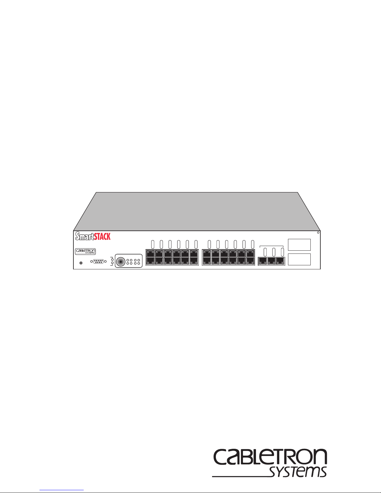
1.1 PRODUCT OVERVIEW
The SmartSTACK Ethernet ELS10-27TX provides a low cost, high performance
solution for 10/100 Mbps switched networks. The SmartSTACK Ethernet
ELS10-27TX is configured wi th twenty-seven RJ 45 ports support ing twenty-four
autonegotiati ng 1 0 Mbps por ts an d th ree autonego tiatin g 10/ 100 Mbp s por ts. Th e
device also features two EPIM-100 slots that allow the user to install up to two
EPIM-100s to provide multimode fiber uplinks (with potential for single mode
fiber). It also includes an RS232C port for local console management.
In ELS10-27TX Version 1.0.1.00, the SmartSTACK Ethernet ELS10-27TX
supports two forms of Virtual LANs. One is the IEEE 802.1Q standard and the
other is a proprietary form that was developed prior to the IEEE standard being
available. The pr oprietary for m is known as Workgroups. V irtual Workgroups are
only supported i n the 802.1D mode and VLANs are only suppo rted in the 80 2.1Q
mode. This manual documents both forms.
Also, modification of existing LCM commands were added that describe how to
set an address limit on a port and how to configure destination IP addresses for
traps. For information on “enable address limit” and “trap control” refer to
Chapter 2, Enhancements to LCM Commands.
This document does not attempt to d escribe the entire functionality of the
SmartSTACK Ethernet ELS10-27TX product, but only differences between
Version 1.00.xx and Version 1.01.00 of the SmartSTACK Ethernet ELS10-27TX
product.
1.2 USING VLANS ON THE ELS10-27TX
This section describes Virtual Local Area Networks (VLANs) support for the
SmartSTACK Ethernet ELS10-27TX switch. This section describes support for
the IEEE 802.1Q standard.
1-1

Introduction
1.2.1 IEEE 802.1Q Standard
IEEE 802.1Q is a standard for virtual bridged local area networks (VLANs). It
provides an alternate method for forwarding packets through a switch. In an
802.1D (Spanning Tree) bridge, packets are forwarded in accordance with the
spanning tree as dynamically created by the 802.1D protocol (Bridge Protocol
Data Units [BPDUs]), and the spanning tree state of each port. In 802.1Q, in
addition to spanning tree, packets are forwarded in accordance with a VLAN tag
that is embedded in the packet, and the set of ports registered for that VLAN. A
set of rules is used for ingress (receipt), forwarding, and egress (transmit).
The SmartSTACK Ethernet ELS10-27TX provides support for port based
VLANs.
The ingress rules deal with the reception of tagged and untagged packets and the
decision to either drop them, or forward them to the forwarding process.
The forwarding rules deal with forwarding packets using topology restrictions,
the filtering database, queue frames (not supported), map priorities (not
supported), and recalculation of the FCS. The forward/filtering database can
contain three types of entries:
• Permanent entries
• Static entries
• Dynamic entries
Dynamic entries are created using the protocols supported by the switch (GVRP).
There will be no learning of VLANs outside of this protocol.
NOTE
There is no support for GVRP with ELS10-27TX Version 1.01.00.
GVRP will be supported in a subsequent release.
The egress rules deal with whether the destination port(s) are members of the
VLAN, and whether the VLAN tag is to be stripped. There is also an issue of
address translation on a packet that is having the VLAN tag stripped. This only
applies to multi-protocol environ ments, such as a combination of Ethernet,
FDDI, and Token Ring protocols and does not apply to the SmartSTACK
Ethernet ELS10-27TX.
The 802.1Q standard does not replace 802.1D. It limits the relaying of packets on
the spanning tree to a subset: the subset being the members of a particular
VLAN. This is determined by comparing th e VLAN ID, which is a field with in
the tag, to the ports which are members of that VLAN.
1-2

Introduction
Tag-aware devices should not exist on a segment
The 802.1Q VLANs spans multiple systems and could span the entire network.
Unlike Workgroups, VLANs are not limited within a particular unit. The
maximum number of VLANs supported in 802.1Q mode on ELS10-27TX is 32.
1.3 802.1Q MODE ON ELS10-27TX
The SmartSTACK Ethernet ELS10-27TX operates in two modes: 802.1D and
802.1Q. While operating in 802.1Q mode, ports can be configured to allow non-
802.1Q devices to operate in this environment.
1.3.1 VLAN Hybrid Ports (802.1Q Mode)
A VLAN Hybrid port is used to connect one or more VLAN-aware or VLANunaware devices to the switch. Both tagged and untagged frames can be received
and transmitted on Hybrid ports.
If a port on the ELS10-27TX is not configured as an Access port, it is a Hybrid
port.
1.3.2 VLAN Access Ports (802.1Q Mode)
The VLAN feature must be used only when non-802.1Q devices are attached to
this port. These ports are known as access ports.
An access command is a sub-command of the port command. An access port is
used to allow each segment to have multiple tag-unaware devices on it, and to
have those devices communicating on multiple VLANs.
An access port has three major characteristics:
1. When a packet is received, it will always insert a tag into the packet.
NOTE
2. When a port transmits a packet, it always strips off the tag, even if it does
not match the default VLAN ID for that port.
3. Additional entries must be placed into the database to support it. When
addresses are learned on access ports, add itional MAC addresses/VLAN ID
pairs are placed into the database to avoid flooding and to establish
connectivity.
connected to an access port.
For further information on Access Ports, refer to Appendix A, Virtual LANs
(VLANs).
1-3

Introduction
1.3.3 802.1Q Trunk Ports
An 802.1Q trunk port passes all packets with the tag in place. It will not strip the
tag. The port must be a hybrid port. There is no explicit command to create
802.1Q trunks ports. The following are two ways of implementing trunk ports:
• Preserving Priority. The default port VLAN ID (PVID) must be identical at
both ends of the tru nk link. The PVID us ed must be a value not us ed anywhere
else in the network to pass traffic. Because this VLAN ID is unique, it will not
be stripped from the packet on egress and therefore will pass the priority bits
intact.
• Non-Preserving Priority . The default port VLAN ID (PVID) must be identical
at both ends of the trunk link . The VLAN ID will be stripped on egress and reinserted on ingress. However, the priority bits will be lost.
NOTE
All VLAN ports by default are hybrid ports.
1.3.3.1 Preserving Priority
The 802.1Q trunk passes all packets with the tag in place. It will not strip the tag.
All packets traversing the link will contain a tag. The administrator should set a
policy that certain VLAN IDs must be reserved and must not be used for traffic.
For example, when reserv ing VLAN IDs 0xf f0 throug h 0xff e, one of th ese can be
used as the PVID for both ends of trunk links. By doing this, the priority bits can
be passed intact. Both ends of the link should be defined as Hybrid so that they
only strip tags if they match the PVID. Because the tag in the packet traversing
the trunk will never match the PVID, it will not be stripped. Also, because the
packet is always received with a tag, the PVID is never inserted.
Preserving priority works best when the end device inserts the tag and supports
priority (priority is not used by the ELS10-27TX, but is passed within the
packet). Therefore, the trunk will not strip a tag or insert a tag, thus the priority
fields are passed intact.
1-4

Introduction
1.3.3.2 Non-Preserving Priority
Use this method if there is no concern about passin g priority from one device to
another. Configure the same P VID at bo th ends of th e trunk l ink to en sure t hat all
traffic will be forwarded correctly.
In order to implement this, the ports at both ends of the link must work the same,
that is:
• Strips tags on egress of the ports that match the PVID
• Inserts a tag using the PVID when there is no tag
• Changes the tag on egress with an ID of zero to the PVID
The tag will be stripped on egress of that port, when it matches the PVID. When
the packet is received by the peer, a tag with the same VLAN ID will be inserted
and the packet will be forwarded as though the packet traversed the trunk link
with the tag in place. However, the priority bits will not be reserved.
1.3.4 Accessing Network Management Using VLANs
When an IP address is configured on the unit, it must be associated with the
VLAN. If multiple VLANs are configured on a switch, you can configure
multiple IP addresses provided they are on separate subnets. Therefore, when an
IP address is assigned to a switch, the VLAN ID for the subnet must be specified.
When the network management processor issues a response to a network
management packet, it selects the correct VLAN ID to use based on the IP
subnet.
For further infor mation, refer to IP A ddress Command or the VLAN Command in
Chapter 2, Enhancements to LCM Commands.
1-5

Introduction
1.3.5 Switch Mode
The unit operates in either an 802.1D or 802.1Q mode. The mode must be
selected by the user and applies to all ports. The unit will not operate in a mixed
mode. The default is to operate in 802.1D mode.
For further information, refer to Switch Command in Chapter 2, En hancements to
LCM Commands.
1.3.6 Assigning Ports to a VLAN
A port becomes a member of a VLAN, by using the VLAN command.
For further information, refer to the Port Command in C hap t er 2, En han cement s
to LCM Comman d s .
1.3.7 Default Port VLAN ID
If the unit is operating in 802.1Q mode, then each port will be configured with a
default port VLAN ID (PVID). The default v alue for each p ort will be th e default
VLAN ID of 0x001. You are allowed to modify this on a per port basis.
When 802.1Q was developed, it was deci ded to configure a defaul t VLAN ID for
a port. If a packet is received on a port that does not have a VLAN ID or does not
have a VLAN ID of zero, the default VLAN ID will be inserted. Once this tag is
in place the packet is sent to the forwarding engine. Once the forwarding engine
receives it, it will use this tag to determine which VLAN to restrict this packet to.
The sub-command of the port command known as the VLAN sub-command is
used to set the default VLAN ID for the port.
NOTE
For further information, refer to Port Command in Chapter 2, Enhancements to
LCM Commands.
There is a sub-command of the port command known as the
VLAN sub-command. This is not used to make a port a member
of the VLAN, and is not directly used in the forwarding and
filtering decision.
1-6

Introduction
1.3.8 Restrict ing VLANs (802.1Q Mode)
This command will allow you to specify a list of VLAN IDs that should not be
dynamically learned by GVRP. When the management processor receives a
GVRP packet, it checks this database to det ermin e if the learning of this ID
should be restricted.
NOTE
There is no support for GVRP with ELS10-27TX Version 1.01.00.
GVRP will be supported in a subsequent release.
For usage, refer to the VLAN Command in Chapter 2, Enhancements to LCM
Commands.
1.3.9 Enable GVRP
GVRP can be enabled on a per port basis using the Port command.
NOTE
For further information, refer to the Port Command in C hap t er 2, En hancements
to LCM Comman d s .
There is no support for GVRP with ELS10-27TX Version 1.01.00.
GVRP will be supported in a subsequent release.
1-7

Introduction
1.4 WORKGROUPS
This section describes Workgroup support for the SmartSTACK Ethernet
ELS10-27TX switch. The switch supports up to eight user defined Workgroups,
with limited support for overlapping Workgroups.
The purpose of Workgroups is to isolate broadcast and multicast traffic to within
the W orkgroup. In some cases, unicast traffic will also be isolated. Due to the fact
that a typical unicast address is obtained by first issuing an ARP packet (which is
a broadcast, and the broadcast packet will not be forwarded outside of the
Workgroup), the unicast address will not be learned outside of the Workgroup.
The end result is that host or servers will not be able to communicate with other
hosts or servers outside of their Workgroup.
Unlike IEEE standard VLANs which span switches, Workgroups only deal with
filtering and forwarding of frames within the single switch. When packets are
received on a port, the packet will be identified with a single Workgroup. The
packet will then be forwarded or filtered based on that single Workgroup
marking. When a packet leaves the switch, the packet will appear just as it did
when it was received on the inbound port.
The SmartSTACK Ethernet ELS10-27TX allows you to define ports for logical
groups of associated devices (virtual workgroups) to provide a more efficient
flow of traffic acros s your Ether net netw ork. You can define a maximum of eight
virtual workgroups. The number of ports within a Workgroup is not restricted
and an individual port can be a member of multiple Virtual Workgroups.
NOTE
Virtual Workgroups will only operate in 802.1D mode.
V irtual workgroups offer the ability to limit broadcasts to logical domains within
the network. Workgroup destinations are recognized by the SmartSTACK
Ethernet ELS10-27TX and broadcast and unicast packets are routed directly to
hosts within the workgroup, eliminating the need to perform a general broadcast
across each segment of the network to find specific host addresses.
For further information, refer to the Wo rkgroup Command in Chapter 5,
Configuring Workgroups Using LCM.
1-8

Introduction
1.5 DEFAULT GATEWAY
A default gateway field was added to the router command to allow
communication to a device on a subnet not configured on this switch.
For information on configuring the Default Gateway, refer to Chapter 2,
Enhancements to LCM Commands.
1.6 I NSTALLATION AND MANAGEMENT
For instructions on how to unpack, install, manage, troubleshoot and cable the
SmartSTAC K Ethernet ELS10-27TX and for a complete list of commands, refer
to the SmartSTACK Ethernet ELS10-27TX User Guide.
1-9

 Loading...