

Page 1

MMAC-Plus
™
9A000, SFCS-200BX,
SFCS-200WG and SFCS-1000
ATM SWITCH
User’s Guide
Page 2

Page 3

i
Notice
Notice
Cabletron Systems reserves the right to make changes in specifications and other information
contained in this document without prior notice. The reader should in all cases consult Cabletron
Systems to determine whether any such changes have been made.
The hardware, firmware, or software described in this manual is subject to change without notice.
IN NO EVENT SHALL CABLETRON SYSTEMS BE LIABLE FOR ANY INCIDENTAL, INDIRECT,
SPECIAL, OR CONSEQUENTIAL DAMAGES WHATSOEVER (INCLUDING BUT NOT LIMITED
TO LOST PROFITS) ARISING OUT OF OR RELATED TO THIS MANUAL OR THE INFORMATION
CONTAINED IN IT, EVEN IF CABLETRON SYSTEMS HAS BEEN ADVISED OF, KNOWN, OR
SHOULD HAVE KNOWN, THE POSSIBILITY OF SUCH DAMAGES.
© Copyright April 1996 by:
Cabletron Systems, Inc.
35 Industrial Way
Rochester, NH 03867-0505
All Rights Reserved
Printed in the United States of America
Order Number: 9031473-03
LANVIEW is a registered trademark of Cabletron Systems, Inc.
MMAC-Plus is a trademark of Cabletron Systems, Inc.
CompuServe is a registered trademark of CompuServe, Inc.
Page 4
ii
Notice
FCC Notice
This device complies with Part 15 of the FCC rules. Operation is subject to the following two
conditions: (1) this device may not cause harmful interference, and (2) this device must accept any
interference received, including interference that may cause undesired operation.
NOTE: This equipment has been tested and found to comply with the limits for a Class A digital
device, pursuant to Part 15 of the FCC rules. These limits are designed to provide reasonable
protection against harmful interference when the equipment is operated in a commercial environment.
This equipment uses, generates, and can radiate radio frequency energy and if not installed in
accordance with the operator’s manual, may cause harmful interference to radio communications.
Operation of this equipment in a residential area is likely to cause interference in which case the user
will be required to correct the interference at his own expense.
WARNING: Changes or modifications made to this device which are not expressly approved by the
party responsible for compliance could void the user’s authority to operate the equipment.
VCCI Notice
This equipment is in the 1st Class Category (information equipment to be used in commercial and/or
industrial areas) and conforms to the standards set by the Voluntary Control Council for Interference
by Information Technology Equipment (VCCI) aimed at preventing radio interference in commercial
and/or industrial areas.
Consequently, when used in a residential area or in an adjacent area thereto, radio interference may be
caused to radios and TV receivers, etc.
Read the instructions for correct handling.
Page 5

Preface
Technical Support.......................................................................................................vii
Typographical Styles..................................................................................................vii
Important Information Indicators ..........................................................................viii
Laser Warning............................................................................................................... x
Safety Agency Compliance........................................................................................ xi
Safety Precautions................................................................................................ xi
Symbols ................................................................................................................. xi
Modifications to Equipment.............................................................................. xii
Placement of a Cabletron Systems Product ....................................................xii
Power Cord Connection.....................................................................................xii
Chapter 1 Introduction
Table of Contents
1.1 Overview of the ATM Standard........................................................................ 1-1
1.2 Hardware Description......................................................................................... 1-2
1.2.1 Front Panel Description ...........................................................................1-4
1.2.2 9A000 and SFCS Series Hardware Configuration................................ 1-4
1.2.3 9A000 and SFCS Series Switch Board .................................................... 1-4
1.2.4 Switch Control Processor......................................................................... 1-5
1.2.5 9A000 and SFCS Series Network Modules ...........................................1-5
1.2.6 Environmental Information..................................................................... 1-5
1.2.7 Standards Compliance .............................................................................1-7
1.2.8 Safety Compliance .................................................................................... 1-7
1.2.9 Emissions Compliance .............................................................................1-7
1.2.10 Electromagnetic Compatibility (EMC) ................................................1-7
1.3 Software Description ........................................................................................... 1-7
1.3.1 Switch Control Software.......................................................................... 1-7
Chapter 2 Installing the 9A000
2.1 Installing the 9A000 ............................................................................................. 2-1
2.2 The Reset Switch ..................................................................................................2-3
Chapter 3 Switch Hardware
3.2 Switch Hardware Components.......................................................................... 3-5
3.2.1 Switch Board.............................................................................................. 3-5
3.2.2 Switch Control Processor......................................................................... 3-5
3.2.2.1 i960 Switch Control Processor .......................................................3-6
3.2.3 Network Modules..................................................................................... 3-9
3.2.3.1 Port Numbering............................................................................... 3-9
3.2.4 Power Supply Modules.......................................................................... 3-11
3.2.4.1 SFCS-200BX AC Power Supply ................................................... 3-11
iii
Page 6

Contents
3.2.4.2 SFCS-1000 AC Power Supply (Model A).................................... 3-12
3.2.4.3 SFCS-1000 AC Power Supply (Model B).................................... 3-15
3.2.5 SFCS-1000 Fan Tray ................................................................................ 3-18
3.2.6 SFCS-1000 Temperature Sensing........................................................... 3-18
3.2.7 SFCS-1000 Common Equipment Card (CEC)..................................... 3-19
3.2.7.1 CEC Front Panel............................................................................. 3-19
3.2.7.2 Alarm Relay Contacts....................................................................3-19
3.2.7.3 CEC Status LEDs............................................................................ 3-21
3.2.7.4 Ethernet Port................................................................................... 3-22
Chapter 4 Switch Setup
4.2 Unpacking .............................................................................................................4-1
4.2.1 Inventorying the Unit................................................................................4-2
4.3 Electrical Considerations.....................................................................................4-3
4.4 Rack-Mounting an SFCS-200BX......................................................................... 4-4
4.4.1 Required Tools............................................................................................ 4-4
4.4.2 Installing the Rack-mount Brackets.........................................................4-5
4.5 Rack-Mounting an SFCS-200WG....................................................................... 4-7
4.5.1 Required Tools............................................................................................ 4-7
4.5.2 Installing the Rack-mount Brackets.........................................................4-8
4.6 Rack-Mounting an SFCS-1000.......................................................................... 4-10
4.6.1 Installing the SFCS-1000.......................................................................... 4-11
4.7 Installing the Serial Cable .................................................................................4-12
4.8 Modem Configuration.......................................................................................4-13
4.8.1 Modem Parameters.................................................................................. 4-13
4.9 Configuring IP Addresses................................................................................. 4-14
4.10 AMI Security..................................................................................................... 4-15
4.11 Subsequent Operation .....................................................................................4-15
4.12 Verifying the Installation................................................................................. 4-16
4.13 Product Registration Information..................................................................4-16
Chapter 5 Hardware Maintenance Procedures
5.1.1 Overview.....................................................................................................5-1
5.1.2 Multicast Mode...........................................................................................5-2
5.1.3 Hot-swapping Network Modules ...........................................................5-3
5.2 Power Supply Module Replacement................................................................. 5-4
5.2.1 SFCS-200BX Power Supply Module Replacement................................5-4
5.2.1.1 Replacing an SFCS-200BX AC Power Supply..............................5-4
5.2.2 SFCS-1000 Power Supply Module Replacement................................... 5-6
5.2.2.1 Replacing an SFCS-1000 AC Power Supply (Model A).............. 5-6
5.2.2.2 Replacing an SFCS-1000 AC Power Supply (Model B).............. 5-9
5.3 SFCS-1000 Fan Tray Replacement.................................................................... 5-12
5.4 Switch Control Processor Replacement ..........................................................5-13
5.5 Switch Board Replacement ...............................................................................5-15
iv
Page 7

Chapter 6 Software Upgrade Instructions
6.1 Obtaining the Software Upgrade File via Diskette ......................................... 6-2
6.2 Performing the Software Upgrade ....................................................................6-4
6.3 Changing between Multiple Versions of Software.......................................... 6-7
6.4 Using bootp to Download Software to the Switch.......................................... 6-9
6.4.1 Overview..................................................................................................... 6-9
6.4.2 Setting Up Your bootp Server .................................................................. 6-9
6.4.3 Adding an Entry for Your Switch in the bootptab File....................... 6-10
6.4.4 Setting Up a tftpboot Server................................................................... 6-12
Appendix A Troubleshooting
A.1.1 Run Looptest ............................................................................................A-3
A.1.2 Check Self-Test (Automatically Performed) ........................................ A-4
A.1.3 Firmware Download (Automatically Performed) ..............................A-4
A.1.4 Hardware Detected by Driver ...............................................................A-5
A.1.5 Check Firmware.......................................................................................A-6
A.1.6 Check Physical Link ................................................................................A-7
A.2 Testing Network Connectivity Using PVCs................................................... A-8
A.2.1 Verifying the Outgoing ATM ARP Entry............................................A-11
A.2.2 atmstat..................................................................................................... A-12
A.2.2.1 No Cells Received by Remote End ...........................................A-13
A.2.2.2 Cells and VPI/VCI Errors Received by Remote .....................A-13
A.2.2.3 Cells and AAL* Errors Received by Remote ...........................A-13
A.2.2.4 Cells and No Errors Received by Remote and Transmitting No
Cells ........................................................................................................A-14
A.2.2.5 Cells and No Errors Received by Remote and Transmitting Cells
A-14
A.3 Collecting Additional Information................................................................ A-15
A.3.1 Basic Information...................................................................................A-15
A.3.2 Adapter Information .............................................................................A-15
A.3.3 Switch Information................................................................................ A-18
Contents
Appendix B SCP Diagnostics
B.1.1 Accessing the Monitor Mode...................................................................B-2
B.1.2 Running the Hardware Tests ...................................................................B-4
B.1.2.1 Clock Test .........................................................................................B-4
B.1.2.2 DRAM Test .......................................................................................B-4
B.1.2.3 DRAM Chip Test .............................................................................B-5
B.1.2.4 Ethernet Test.....................................................................................B-5
B.1.2.5 FLASH Test ......................................................................................B-5
B.1.2.6 FLASH Chip Test.............................................................................B-6
B.1.2.7 Serial Port Test .................................................................................B-7
B.1.2.8 SRAM Test ........................................................................................B-7
B.1.2.9 Timer Test .........................................................................................B-7
B.1.2.10 Hardware Test................................................................................B-7
B.1.2.11 Complete Hardware Test..............................................................B-8
v
Page 8

Contents
Appendix C Hardware Specifications
C.1.1 SFCS-200WG............................................................................................ C-2
C.1.2 SFCS-200BX.............................................................................................. C-3
C.1.3 SFCS-1000..................................................................................................C-4
C.2 ATM Network Modules.................................................................................... C-5
C.2.1 100 Mbps TAXI Module ..........................................................................C-5
C.2.2 155 Mbps OC-3c/STM-1 MM Module.................................................. C-6
C.2.3 155 Mbps STS-3c/STM-1 UTP Module................................................. C-7
C.2.3.1 155 Mbps UTP Pinout Specifications ..........................................C-8
C.2.3.2 Connecting Switches with 155 Mbps UTP Network Modules C-8
C.2.4 622 Mbps OC-12c/STM-4c MM Module ..............................................C-9
C.2.5 25 Mbps TP25 Module........................................................................... C-10
C.2.5.1 Connecting Switches with TP25 Network Modules............... C-11
C.2.5.2 Connecting Switches with Token Ring Pinouts to Cabletron
Switches ................................................................................................. C-11
C.2.5.3 Connecting Adapters with Token Ring Pinouts to Cabletron
Switches ................................................................................................. C-12
C.2.6 34 Mbps E3 Module ............................................................................... C-13
C.2.7 45 Mbps DS3 Module ............................................................................ C-14
C.2.8 155 Mbps OC-3c/STM-1 SM Module.................................................. C-15
C.2.9 155 Mbps OC-3c/STM-1 3MM/1SM Module.................................... C-16
C.2.10 622 Mbps OC-12c/STM-4c SM Module............................................ C-18
C.3 ATM Adapters.................................................................................................. C-19
C.3.1 Adapter Cabling Specifications............................................................ C-19
C.3.1.1 Fiber-Optic Cable Specifications................................................ C-19
C.3.1.2 UTP Cable Specifications ............................................................C-20
C.3.1.3 UTP Pinouts.................................................................................. C-20
C.3.2 ESA-200PC Technical Specifications.................................................... C-21
C.3.3 PCA-200PC Technical Specifications ................................................... C-22
C.3.4 PCA-200MAC Technical Specifications .............................................. C-23
C.3.5 NBA-200 Technical Specifications........................................................ C-24
C.3.6 GIA-200 Technical Specifications .........................................................C-25
C.3.7 HPA-200 Technical Specifications........................................................ C-26
C.3.8 MCA-200 Technical Specifications....................................................... C-27
C.3.9 SBA-200 Technical Specifications .........................................................C-28
C.3.10 ESA-200 Technical Specifications .......................................................C-29
C.3.11 VMA-200 Technical Specifications..................................................... C-30
vi
Page 9

PREFACE
This manual provides technical information needed to install and operate the
Cabletron
vides information for the 9A000 and SFCS-200BX switches and the userinstallable network modules offering both LAN and WAN interfaces. This
document also provides safety instructions, general product information, network configuration information and information on software administration
capabilities.
TM
9A000 and SecureFast Cell Switch-200BX ATM Switches. It pro-
Technical Support
In the U.S.A., you can contact Cabletron Systems’ Technical Support by any
By phone: Monday through Friday between 8 A.M. and
By CompuServe
By Internet mail: support@ctron.com
By mail: Cabletron Systems, Inc.
By FAX: (603) 335-4743
Technical support for non-U.S.A. customers should be handled through your
local distributor.
No matter which method is used for technical support, please be prepared to
provide your support contract ID number, the serial number(s) of the product(s), and as much information as possible describing your problem/question.
®
one of four methods:
8 P.M. Eastern Standard Time at (603) 3329400
: GO CTRON from any ! prompt
P.O. Box 5005
Rochester, NH 03867-0505
Typographical Styles
Throughout this manual, all specific commands meant to be entered by the
user will appear on a separate line in bold
tion, use of the
lowing example demonstrates this convention.
Enter
or
Return
Avant Garde typeface. In addi-
key will be represented as
<ENTER>
. The fol-
vii
Page 10

PREFACE
Important Information Indicators
cd /usr <ENTER>
Commands or file names that appear within the text of this manual will be
represented in the following style: “...the
distribution”.
As in the following example, any messages that appear on your screen during
software installation and network interface administration will appear in
Courier font to distinguish them from the rest of the text.
....
Are all four conditions true?
To call your attention to safety and otherwise important information that
must be reviewed to insure correct and complete installation, as well as to
avoid damage to the ForeRunner Switch or your system, Cabletron Systems
utilizes the following WARNING/CAUTION/NOTE indicators.
WARNING statements contain information that is critical to the safety of the
operator and/or the system. Do not proceed beyond a WARNING statement
until the indicated conditions are fully understood or met. This information
could prevent serious injury to the operator, damage to the ForeRunner
Switch, the system, or currently loaded software, and will be indicated as follows:
fore_install
program will install this
viii
WARNING!
Information contained in CAUTION statements is important for proper
installation/operation. CAUTION statements can prevent possible equipment damage and/or loss of data and will be indicated as:
CAUTION
Hazardous voltages are present. If the instructions are not heeded, there is a risk of electrical
shock and danger to personal health.
You risk damaging your equipment and/or
software if you do not follow these
instructions.
Page 11

PREFACE
Information contained in NOTE statements has been found important
enough to be called to the special attention of the operator and will be set off
from the text as follows:
NOTE:
Cabletron Systems strongly recommends that
you disconnect the serial cable once you have
configured the ATM switch and then access
the switch over the ATM network.
ix
Page 12

PREFACE
Laser Warning
Class 1 Laser Product:
This product conforms to
applicable requirements of
21 CFR 1040 at the date of
manufacture.
Class 1 lasers are defined as products which do not permit human access to
laser radiation in excess of the accessible limits of Class 1 for applicable wavelengths and durations. These lasers are safe under reasonably foreseeable
conditions of operation.
The following network modules contain Class 1 lasers:
NM-2/155SMSRA-1 NM-2/155SMSRB-1 NM-2OC3/SMSRA-1
NM-4/155SMSRA-1 NM-4/155SMSRB-1 NM-4OC3/SMSRA-1
NM-4OC3/SMSRA-1A NM-4OC3/SMSRB-1 NM-2/155SMSRC
NM-4/155SMSRC NM-2/155SMLRA-1 NM-2/155SMLRB-1
NM-2/155SMLRC-1 NM-2OC3/SMLRB-1 NM-2OC3/SMMRA-1
NM-4/155SMLRB-1 NM-4/155SMLRC-1 NM-4OC3/SMLRB-1
NM-4OC3/SMMRA-1 NM-1/622SMIRC NM-4/155LR3SCC
NM-4/155SR3SCC
x
Page 13

Safety Agency Compliance
This preface provides safety precautions to follow when installing a
Cabletron Systems, Inc., product.
Safety Precautions
For your protection, observe the following safety precautions when setting up
your equipment:
• Follow all warnings and instructions marked on the equipment.
• Ensure that the voltage and frequency of your power source matches
the voltage and frequency inscribed on the equipment’s electrical rating label.
• Never push objects of any kind through openings in the equipment.
Dangerous voltages may be present. Conductive foreign objects
could produce a short circuit that could cause fire, electric shock, or
damage to your equipment.
PREFACE
Symbols
The following symbols appear in this book:
WARNING!
CAUTION
Hazardous voltages are present. If the instructions are not heeded, there is a risk of electrical
shock and danger to personal health.
You risk damaging your equipment and/or
software if you do not follow these
instructions.
xi
Page 14
PREFACE
Modifications to Equipment
Do not make mechanical or electrical modifications to the equipment.
Cabletron Systems, Inc., is not responsible for regulatory compliance of a
modified product.
Placement of a Cabletron Systems Product
CAUTION
To ensure reliable operation of your Cabletron
Systems product and to protect it from overheating, openings in the equipment must not
be blocked or covered. A Cabletron Systems
product should never be placed near a radiator or heat register.
Power Cord Connection
WARNING!
WARNING!
Cabletron Systems products are designed to
work with single-phase power systems having a grounded neutral conductor. To reduce
the risk of electrical shock, do not plug
Cabletron Systems products into any other
type of power system. Contact your facilities
manager or a qualified electrician if you are
not sure what type of power is supplied to
your building.
Your Cabletron Systems product is shipped
with a grounding type (3-wire) power cord. To
reduce the risk of electric shock, always plug
the cord into a grounded power outlet.
xii
Page 15

CHAPTER 1
The Cabletron 9A000 and SFCS series ATM Switch brings ATM connectivity to
LAN workgroup, LAN backbone, and LAN/WAN internetworking applications. Together with the Cabletron series of ATM Computer Interfaces, the
9A000 and SFCS series meet the networking demands of today’s distributed,
time-critical applications.
The Cabletron 9A000 and SFCS series ATM high-performance ATM switches
deliver switching capacity and speed for ATM applications. A non-blocking
switching capacity of 2.5 Gbps is continually available for connectivity to 16
users or networking devices, each running at speeds up to 622 Mbps or 24
users or network devices running at 100 Mbps.
This chapter provides an overview of the ATM Standard and Cabletron Systems 9A000 and SFCS series Switches. It details the hardware and software
requirements necessary to use the 9A000 and SFCS series and also provides
information on the contents of the 9A000 and SFCS series Switch packages.
Introduction
1.1 Overview of the ATM Standard
Asynchronous Transfer Mode, or ATM, is a communication architecture
based on the switching of small fixed length packets of data called cells . In
ATM, all data is transferred in 53-byte cells. Each cell has a 5-byte header that
identifies the cell’s route through the network and 48-bytes containing user
data. This user data in turn carries any headers or trailers required by higher
level protocols.
The operation of an ATM switch is conceptually quite simple. The header of
each cell contains a virtual connection (VC) identifier, consisting of a virtual
path identifier (VPI) and a virtual channel identifier (VCI). On each incoming
link, an arriving cell’s VC identifier uniquely determines a new VC identifier
to be placed in the cell header, and the outgoing link over which to transmit
the cell. In the case of a multicast connection, the VC identifier maps to a set of
new VC identifiers and outgoing links.
Perhaps the single most important advantage offered by ATM, in addition to
the speed at which data is transferred, is its open-ended growth path. ATM is
not locked into a single physical medium or speed. The fixed-size ATM cell
allows traffic from multiple sources (simultaneous video, audio, and data
1-1
Page 16

Introduction
1.2 Hardware Description
communication) to be switched to multiple destinations by fast ATM switches
such as the Cabletron 9A000 and SFCS series (connecting up to 64 workstations
with an aggregate capacity of 2.5 Gbps or 96 workstations running at 100
Mbps). Larger LANs can be built by interconnecting multiple 9A000 and SFCS
series ATM switches.
Based upon international standards developed by the CCITT, ATM allows for
fast packet switching of cells, 53 bytes in length. By using small cells to transfer data, coupled with a low latency switch supporting isochronous timing,
ATM is able to support a wide range of audio, video, image, and data communications requirements.
Unlike shared-medium LAN technologies such as Ethernet and Token Ring,
in which users must contend for bandwidth, ATM switching provides dedicated, deterministic, high-speed connectivity. In addition, ATM is scalable
from 155 Mbps to 2.5 Gbps - to the desktop, or for the entire network.
The 9Cabletron 9A000 and SFCS series ATM switches, as shown in Figure 1-1
and Figure 1-2, provide connectivity for up to 16 computer workstations,
hubs, or routers at rates operating up to 622 Mbps/sec (or 24 workstations
running at 100 Mbps) via dedicated fiber optic links and twisted pair links.
Wide-area network (WAN) connectivity is seamlessly integrated into the
9A000 and SFCS series for connection to private networks or ATM SONET,
DS-3, DS-1, E-3, or J-2 services.
Interconnecting multiple 9A000 and SFCS series switches at various speeds is
simple. Once a new 9A000 and SFCS series switch is added to the network,
all other switches recognize its presence and dynamically establish connections to ports on the new switch. Furthermore, scaling the network is accomplished without costly and time consuming address reconfiguration and LAN
segmentation.
The 9A000 and SFCS series is a self-contained ATM switch that includes an
Ethernet connection to provide network management access.
1-2
Page 17
Introduction
Figure 1.1 - 9A000 Switch Configuration
1-3
Page 18
Introduction
SecureFast Cell Switch
5 VOLT
RX2
RESET
RX2
RX1
TX2
TX1
RX2
RX1
TX1
Tx
C
ETH
SER
RX3
TX2
TX3
Rx
L
SELECT
NEXT
RX4
RX3
TX4
TX3
RX4
TX4
SFCS
PWR
RESET
RX1
TX2
TX1
RX2
RX1
TX2
TX1
Tx
Rx
L
C
SER
ETH
Figure 1.2 - SFCS-200BX Switch Configuration
1.2.1 Front Panel Description
The front panel of the 9A000 and SFCS series includes the following features:
a power switch, two power supply LEDs, a RESET button, an RS-232 serial
port, an Ethernet 10BaseT port, a NEXT pushbutton, a SELECT pushbutton, a
display LED, and a power LED. For more information about these features,
please refer to Appendix A of this manual.
1.2.2 9A000 and SFCS Series Hardware Configuration
The 9A000 and SFCS series hardware consists of a switch board, an i960
switch control processors, and network modules. These components work
together to provide ATM switching capabilities, as well as distributed connection set-up and management. A functional description for each component
follows.
NEXT
RX3
TX3
RX3
TX3
FORE - FORE
SELECT
-200BX
5 VOLT
RX4
TX4
RX4
TX4
PWR
1-4
1.2.3 9A000 and SFCS Series Switch Board
The 9A000 and SFCS series switch board contains the VPI/VCI lookup tables,
and routing circuitry to ensure that a cell received from an input port is correctly switched to one or more output ports. The 9A000 and SFCS series
switch board can accept up to four network modules, which themselves contain up to six ports each. The switch board also has an interface, controlled by
the switch control processor, that is functionally equivalent to an ATM host
interface. (See Switch Control Software for more information).
Page 19

1.2.4 Switch Control Processor
The i960 switch control processor provides the distributed connection set-up
for a network of ATM switches. The switch control processor primarily provides management access through SNMP and is responsible for storing and
updating all SNMP management information. Additionally, the switch control processor can access the ATM switch in-band in very much the same
manner as an ATM adapter in a workstation (such as the Fore SBA-200 SBus
Adapter). Since it has the ability to communicate over IP, the 9A000 and SFCS
series can route IP traffic from one given IP network to another. The switch
control processor, and associated software, manages the behavior of the
9A000 and SFCS series switch board (i.e., connection setup), but is not
involved in the actual cell switching.
1.2.5 9A000 and SFCS Series Network Modules
The network modules for the 9A000 and SFCS series act as the physical
input/output ports to the 9A000 and SFCS series switch. A network module
may have up to six physical ports, depending on its physical configuration.
There is also a logical control port located inside the SCP which is referred to
in the switch software as the Control Port (CTL). This control port is a logical
(not physical) location where cells that are directed to the SCP itself are sent.
(See section 1.4.1 for more information.)
Introduction
1.2.6 Environmental Information
In the 9A000 and SFCS series, there is a temperature sensor, located over the
switch fabric area of the enclosure, which ensures that the internal cabinet
temperature is not too high. This temperature is displayed on the Environmental Module LCD readout, within the MMAC Plus chassis. The power utilization for the 9A000 and SFCS series is also monitored and can be displayed
on the Environmental Module.
1-5
Page 20

Introduction
Table 1.1 - System Hardware and Environmental Specifications
Features SFCS Series/9A000
Switching Fabric
Traffic Policing
Number of Ports
Switch Transit Delay
Connection Setup Time < 10 milliseconds
Maximum Port Speed
Power (nominal) 90 - 270 VAC @ 47 - 63 Hz
Dimensions H: 4.75” (12.1 cm)
Weight 43 lbs (19.5 kg)
Operating Temperature 5˚C to 40˚C
2.5 Gbps
non-blocked
UNI 3.1 dual leaky
bucket support
up to 24 ports
< 10 microseconds
622 Mbps
(OC-12/STM-4)
2.2 amps maximum
W: 17.5” (44.5 cm)
D: 18” (45.7 cm)
up to 10,000 ft
1-6
Operating Humidity 10 to 90% RH
Storage Temperature -40˚C to 70˚C
up to 30,000 ft
Storage Humidity 5 to 95% RH
Page 21

1.2.7 Standards Compliance
• ITU I.361 ATM Layer
• ATM Forum UNI 3.0
1.2.8 Safety Compliance
• US: UL 1950
• Canada: CSA 22.2 No. 950-M89
• Europe: EN 60950
1.2.9 Emissions Compliance
• FCC Part 15, Class A
• CISPR 22, Class A
• VCCI, Class 1
1.2.10 Electromagnetic Compatibility (EMC)
The following all comprise EN 50082-1:
• ESD Susceptibility: IEC 801-2, Level 3
• Radiated Susceptibility: IEC 801-3, Level 2
• Electrical Fast Transient Compatibility: IEC 801-4, Level 2
Introduction
1.3 Software Description
The software for the 9A000 and SFCS series runs on a FLASH file system to
accomplish switch and connection management, IP connectivity, and SNMP
network management.
1.3.1 Switch Control Software
The Switch Control Software (SCS) is the “brains” of the 9A000 and
SFCS series switches. The SCS controls the 9A000 and SFCS series switch
board and handles connection set-up and tear-down duties. The SCS can also
communicate with other Cabletron Systems switches using the SPANS NNI
protocol to learn network topology and establish connections across multiple
switches. In addition, there is an SNMP agent built into the SCS to allow
SNMP management and control.
1-7
Page 22

Introduction
1-8
Page 23

CHAPTER 2 Installing the 9A000
This chapter contains the procedures for installing the 9A000. The installation
of the SFCS series is covered in Chapter 3.
2.1 Installing the 9A000
To install the Cabletron 9A000, follow the steps below:
1. Switch off the power supplies and remove all power from the
MMAC-Plus chassis.
2. Remove the blank panels, covering the slots that the module is
being mounted in. All other slots must be covered, if modules are
not being installed, to ensure proper airflow and cooling.
3. Carefully remove the module from the shipping box. (Save the
box and packing materials in the event the module must be
reshipped.)
4. Attach one end of the ESD wrist strap packaged with the MMAC-
Plus chassis to your wrist. Plug the other end into the ESD Wrist
Strap Grounding receptacle in the lower right corner of the
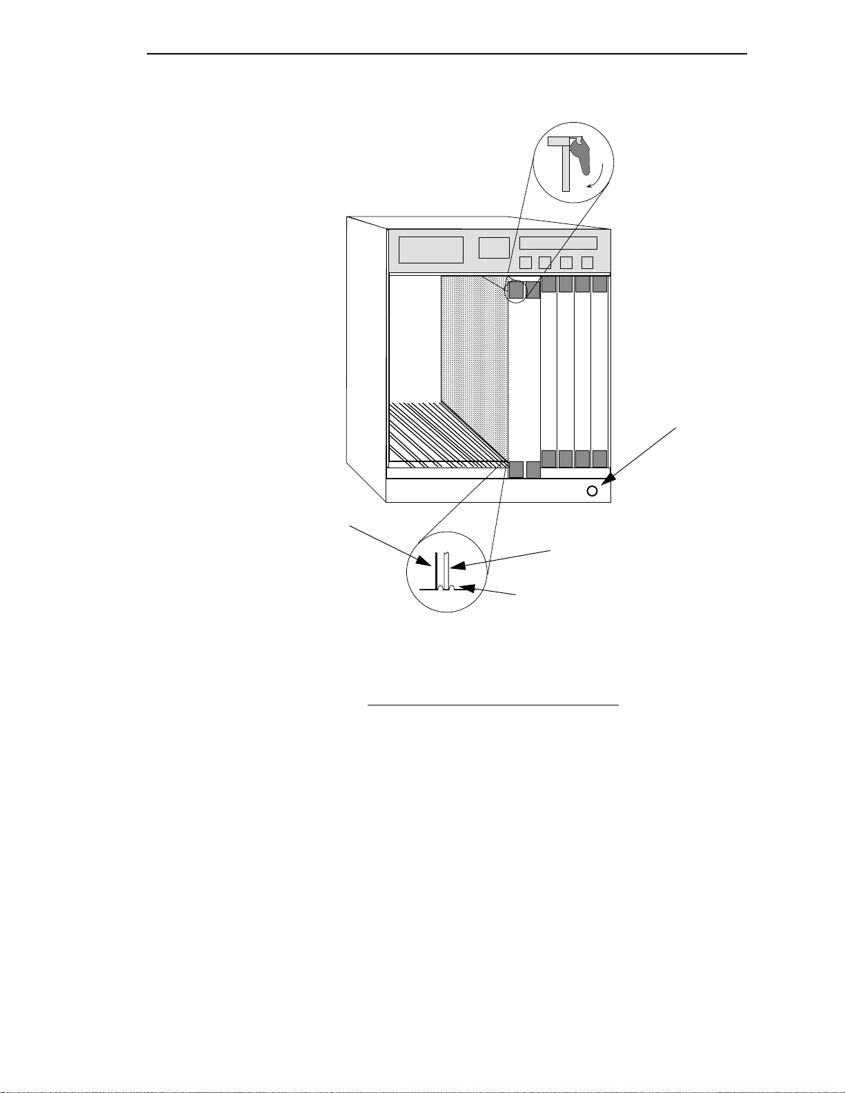
MMAC-Plus Chassis shown in Figure 2.1.
5. Remove the module from the plastic bag. Observe all precautions
to prevent damage from Electrostatic Discharge (ESD).
6. Carefully examine the module, checking for damage. If any dam-
age exists, DO NOT install the module. Contact Cabletron
Systems Technical Support immediately.
7. The modules are installed into the chassis by sliding them into
slots and locking down both the top and bottom plastic tabs, as
shown in Figure 2.1. Take care that the module slides in straight
and engages the backplane connectors properly. When installing
the module, ensure that both circuit cards are between the card
guides, as shown in Figure 2.1. Check both the upper and lower
tracks of both cards.
2-1
Page 24
Installing the 9A000
7
FLNK
8
FLNK
FLNK
10
RX
FLNK
INS
TX
11
RX
FLNK
INS
TX
12
RX
Jack for ESD
wrist strap
2-2
Metal Back-Panel
Circuit Card
Card Guides
Warning:
Ensure that the circuit card is between the card guides.
Lock down the top and bottom plastic tabs
at the same time, applying even pressure.
Figure 2.1 - Installing the 9A000 Module
Page 25

2.2 The Reset Switch
SMB
CPU
The Reset switch is located on the rightmost front panel, under the top plastic
tab as shown in Figure 2.2. It serves two functions:
• Pressing the reset switch twice within three seconds causes the processor (i960) to reset.
• Pressing and holding the switch on for three or more seconds causes
the module to shutdown. Pressing and holding again for three seconds restarts the module.
SNMP management may be used to disable this switch to enhance module
security.
Installing the 9A000
Reset Switch
Figure 2.2 - The Reset Switch
2-3
Page 26

Installing the 9A000
2-4
Page 27

CHAPTER 3 Switch Hardware
Cabletron Systems offers a full line of ATM products that work together to
provide a complete ATM network solution. The Cabletron SFCS-200WG ATM
switch provide high-performance ATM connectivity for LAN workgroup and
desktop applications. The SFCS-200BX ATM switch and the SFCS-1000 ATM
switch offer high reliability and port density for LAN backbone and LAN/
WAN internetworking applications. Together with the Cabletron series of
ATM LAN and WAN Network Modules, these switches meet the networking
demands of today’s distributed, time-critical applications.
All of the Cabletron ATM switches deliver high-performance switching
capacity and speed for ATM applications. A non-blocking switching capacity
of 2.5 Gbps is continually available on the SFCS-200WG, and the SFCS-200BX.
Each switch provides up to 4 ports of connectivity, each running at speeds up
to 622 Mbps; or up to 16 ports, each running at speeds up to 155 Mbps; or up
to 24 ports, each running at speeds up to 100 Mbps. The
10 Gbps of switching capacity for up to 16 ports of connectivity, each running
at speeds up to 622 Mbps; or up to 64 ports, each running at speeds up to 155
Mbps; or up to 96 ports, each running at speeds up to 100 Mbps.
Wide-area network (WAN) connectivity is seamlessly integrated into the
SFCS-200BX and the SFCS-1000 for connection to private networks or ATM
SONET, DS3 and E3 services.
Interconnecting multiple Cabletron switches at various speeds is simple.
Once a new Cabletron switch is added to the network, all other switches recognize its presence and dynamically establish connections to ports on the
new switch. Furthermore, scaling the network is accomplished without costly
and time consuming address reconfiguration and LAN segmentation.
This chapter provides an overview of the Cabletron Systems’ family of ATM
switches. It details the hardware requirements necessary to use these switches
and also provides information on the contents of each of the switch packages.
SFCS-1000 provides
3-1
Page 28
Switch Hardware
3.1 Switch Hardware Configurations
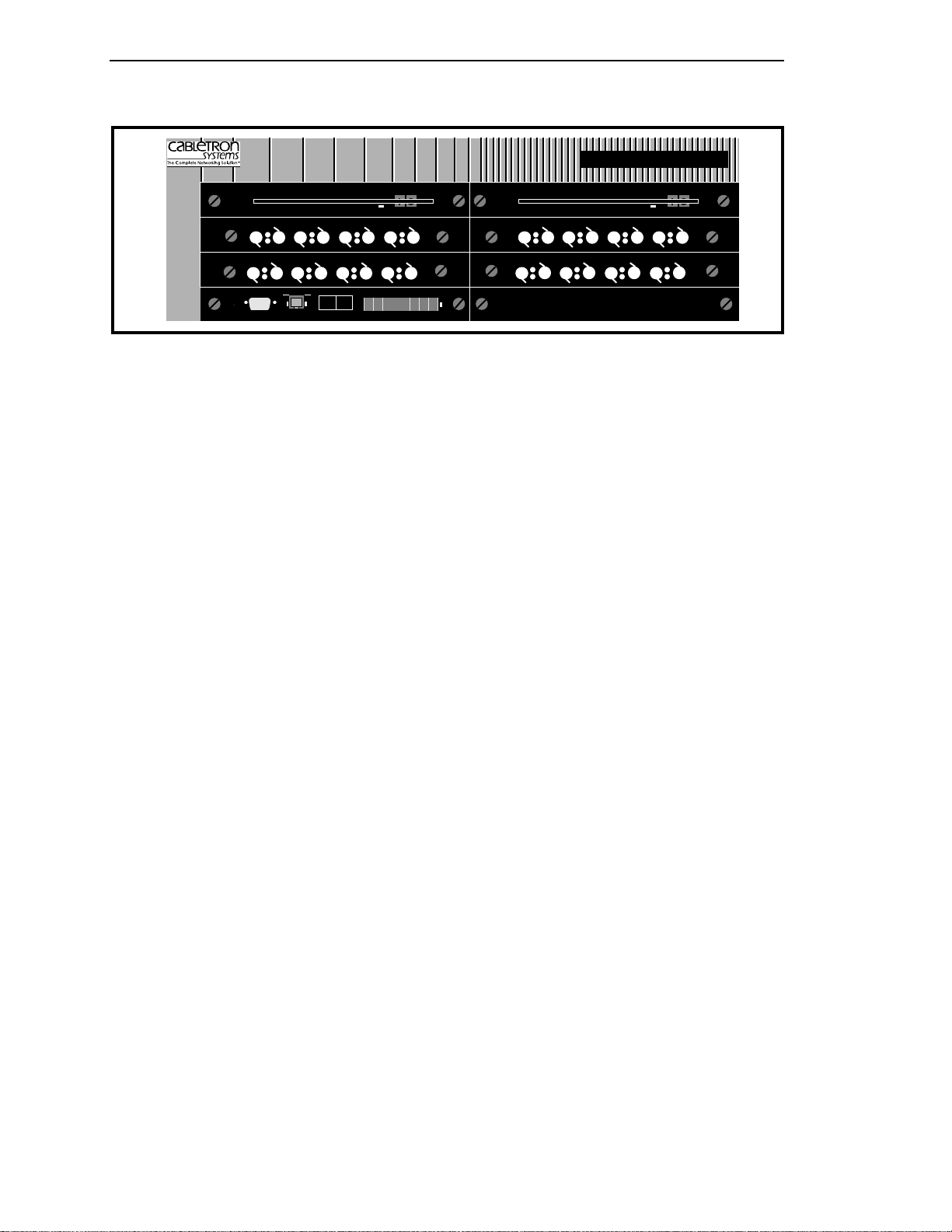
The SFCS-200WG, as shown in Figure 3.1, is a self-contained ATM switch that
provides an Ethernet connection for network management access. The
SFCS-200WG ATM switch hardware consists of a single switch board with an
i960 SCP, network modules, and fans. These components work together to
provide ATM switching capabilities, as well as distributed connection setup
and management.
SYSTEMS
RESET
SecureFast
RX2
RESET
RX1
TX2
TX1
RX2
RX1
TX2
TX1
Tx
Rx
L
C
SER
NEXT
ETH
RX2
RX1
TX2
TX1
RX2
RX1
TX1
Tx
C
ETH
SER
RX3
TX2
TX3
Rx
L
SELECT
NEXT
RX4
RX3
TX4
TX3
RX4
TX4
PWR
RX3
SELECT
RX3
TX3
TX3
-
SFCS-200WG
5 VOLT
RX4
TX4
RX4
TX4
PWR
Figure 3.1 - SFCS-200WG Switch Configuration
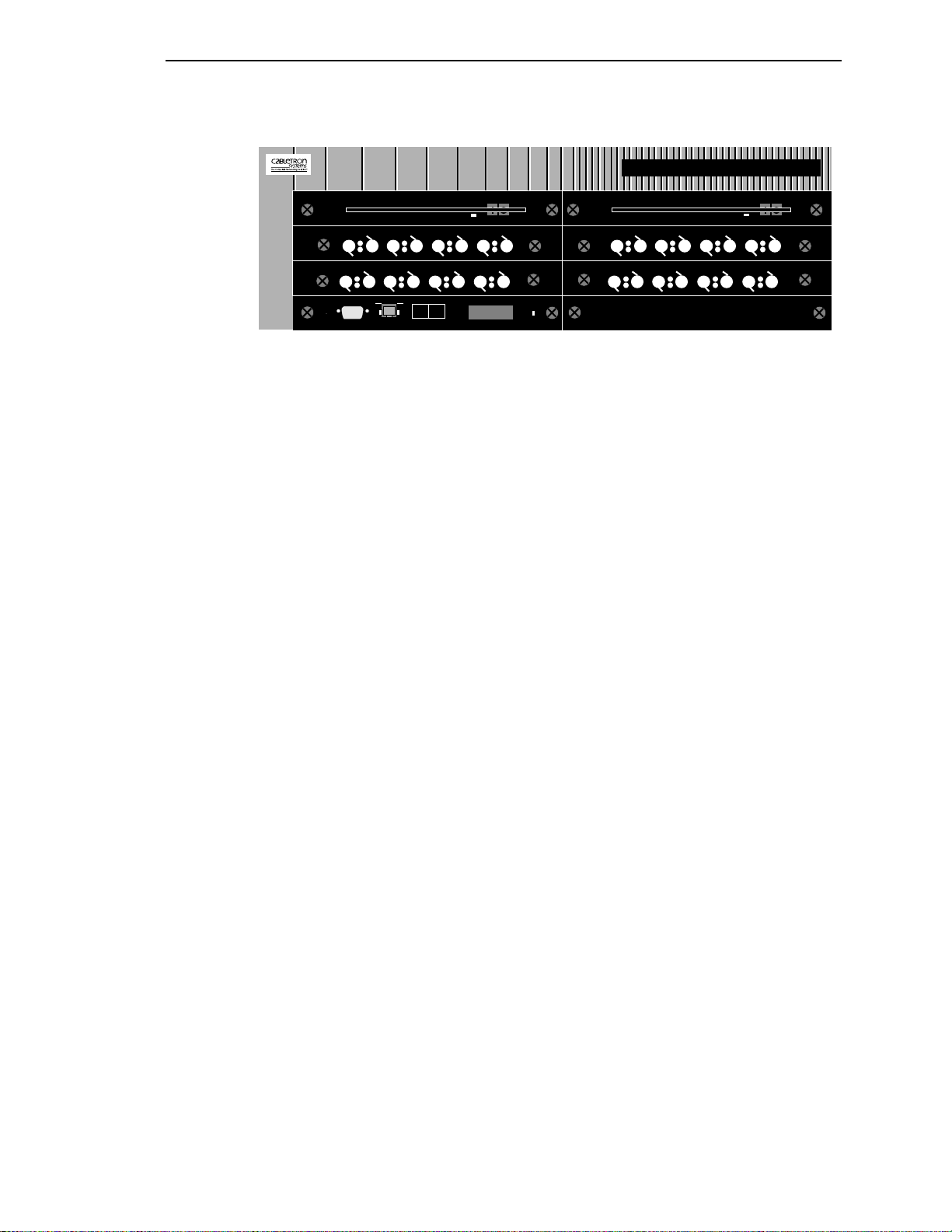
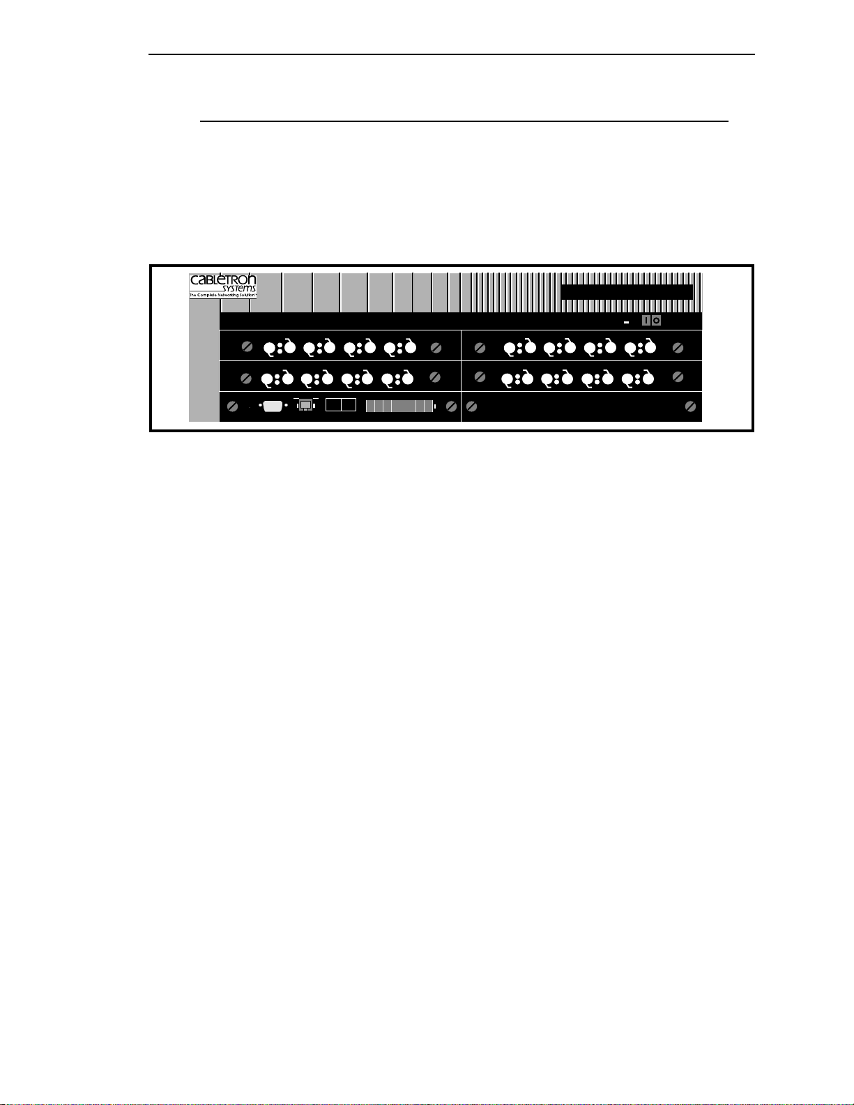
The SFCS-200BX, as shown in Figure 3.2, is a self-contained ATM switch that
provides an Ethernet connection for network management access. The
SFCS-200BX hardware consists of a single switch board with an i960 SCP, network modules, redundant power supplies, and fans. These components work
together to provide ATM switching capabilities, as well as distributed connection setup and management.
3-2
Page 29
Switch Hardware
SYS
5 VOLT
RX1
TX1
RX1
TX1
RESET
SER
RESET
RX2
RX1
TX2
TX1
RX2
RX1
TX1
Tx
C
ETH
SER
RX3
TX2
TX3
Rx
L
SELECT
NEXT
RX4
RX3
TX4
TX3
RX4
TX4
PWR
SecureFast SFCS
RX2
TX2
RX2
TX2
Tx
Rx
L
C
NEXT
ETH
SELECT
RX3
TX3
RX3
TX3
SFCS-200BX
5 VOLT
RX4
TX4
RX4
TX4
PWR
Figure 3.2 - SFCS-200BX Switch Configuration
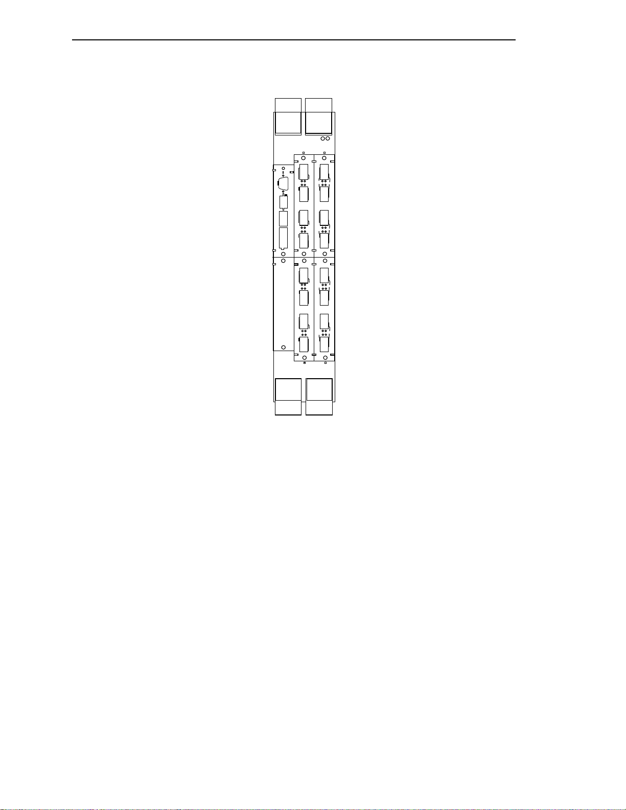
The SFCS-1000, as shown in Figure 3.3, is a self-contained ATM switch that
provides an Ethernet connection for network management access. The hardware for the SFCS-1000 consists of up to four switch boards, each with an i960
SCP; network modules; redundant power supplies; a Common Equipment
Card (CEC); and a removable fan tray. These components work together to
provide ATM switching capabilities, as well as distributed connection setup
and management.
3-3
Page 30

Switch Hardware
SYSTEMS
SFCS-1000
C
A
AL1 AL2
AL1 AL2
AL2
AL1
AL1
AL2
RX
LI
ETH
RX
LI
COL
POL
ETH
COL
POL
RESET
SER
Tx
C
ETH
Rx
L
NEXT SELECT
PWR
RX1
TX1
RESET
RX1
TX1
RX2
TX2
TX3
TX4
TX1
TX2
TX3
TX4
SER
RX2
TX2
Tx
C
ETH
Rx
L
NEXT SELECT
RX3
TX3
RX3
RX4
RX4
TX4
PWR
TX1 RX1 TX2 RX2 TX3 RX3 TX4 RX4
RX1
RX2
RX3
RX4
C
A
RX1
TX1
RX1
TX1
RX2
TX2
RX3
TX3
RX4
TX4
RX1
TX1
RX2
TX2
RX3
TX3
RX4
TX4
RESET
SER
RX2
TX2
Tx
C
ETH
Rx
L
NEXT SELECT
RX3
TX3
RX4
TX4
PWR
TX1 RX1 TX2 RX2 TX3 RX3 TX4 RX4
C
A
TX1
RX1
RESET
RX1
TX1
TX2
TX3
TX4
TX1
TX2
TX3
TX4
SER
RX2
TX2
RX2
Tx
C
ETH
Rx
L
NEXT SELECT
RX3
TX3
RX3
RX4
TX4
RX4
PWR
TX1 RX1 TX2 RX2 TX3 RX3 TX4 RX4
RX1
RX2
RX3
RX4
C
A
RX1
TX1
RX1
TX1
TX2
RX2
RX2
TX2
TX3
RX3
TX3
RX4
TX4
TX4
RX1
TX1
48V DC
48V DC
RX3
RX4
CB1
CB1
TX1 RX1 TX2 RX2 TX3 RX3 TX4 RX4
110
RX2
TX2
RX3
TX3
F12A/250V
RX4
TX4
F12A/250V
TB1TB1
3-4
D
B
D
B
D
B
B
Figure 3.3 - SFCS-1000 Switch Configuration
D
AC V olt. In
AC V olt. In
Page 31

3.2 Switch Hardware Components
3.2.1 Switch Board
The switch board (also referred to as the “switch fabric”) contains the VPI/
VCI lookup tables and routing circuitry to ensure that a cell received from an
input port is correctly switched to one or more output ports. The SFCS200WG, and the SFCS-200BX each come with one switch board. The
SFCS-1000 can be populated with as many as four switch boards. Each switch
board can accept up to four network modules, which themselves can contain
up to six ports each. The switch board also has an interface, controlled by the
SCP, that is functionally equivalent to an ATM host interface.
3.2.2 Switch Control Processor
The i960 SCP in the SFCS-200WG, SFCS-200BX, and the SFCS-1000 provide
the distributed connection setup for a network of ATM switches. The SCP primarily provides management access through SNMP and is responsible for
storing and updating all SNMP management information. Additionally, the
SCP has direct access to the switch board. The SCP, and associated software,
manages the behavior of the switch board (i.e., connection setup), but is not
involved in the actual cell switching.
Switch Hardware
3-5
Page 32

Switch Hardware
3.2.2.1 i960 Switch Control Processor
The front panel of an i960 SCP for the SFCS-200WG, SFCS-200BX, and the
SFCS-1000 includes the following features: a RESET button, an RS-232 serial
port, an Ethernet 10BaseT port, a NEXT pushbutton, a SELECT pushbutton, a
display LED, and a power LED. All of the features are illustrated in Figure 3.4
and are described in detail in the subsections that follow.
RESET
SER
Tx
C
ETH
Rx
L
NEXT SELECT
Figure 3.4 - i960 Switch Control Processor Front Panel
3.2.2.1.1 RESET Button
The RESET button allows the user to reset the switch control software on the
SCP. Using RESET “soft boots” the SCP and runs the initial power-on diagnostics. All open AMI sessions are ended by the SCP, and all ports lose any
active sessions and initially go off-line after a reset. The ports then return to
the configuration stored in the CDB. Because the RESET button is small (to
avoid accidental resets), it is recommended that you use a straightened paper
clip to push the RESET button.
3.2.2.1.2 RS-232 Serial Port
The RS-232 serial port provides terminal access for any VT100 (or similar) terminal or terminal emulation package to the SCP. The serial port has a standard DB-9 female connector as shown in Figure 3.5.
PWR
3-6
4
5
987
3
21
6
Figure 3.5 - RS-232 Serial Port Pinouts
Page 33

Switch Hardware
Table 1.1 describes the RS-232 serial port pinouts that are illustrated in
Figure 3.5.
Table 3.1 - RS-232 Serial Port Pinouts
Pin Number
1 DCD Data Carrier Detect
2 RXD Receive Data
3 TXD Transmit Data
4 DTR Data Terminal Ready
5 GND Signal Ground
6 DSR Data Set Ready
7 RTS Request to Send
8 CTS Clear to Send
9 Not Used
3.2.2.1.3 Ethernet 10BaseT Port
The Ethernet 10BaseT port on the front panel of the SCP has a standard RJ45
connector. There is a transmit LED to the left of this port and a receive LED to
the right of this port. Tables 1.2 and 1.3 describe the states of the LEDs and
their meanings.
Table 3.2 - Ethernet 10BaseT Transmit LED Description
Signal
Mnemonic
Signal Name
LED Color Meaning
red There is a collision on the port.
green The port is transmitting normally.
Table 3.3 - Ethernet 10BaseT Receive LED Description
LED Color Meaning
red The port is failing link integrity.
green The port is receiving normally.
3-7
Page 34

Switch Hardware
3.2.2.1.4 CTL Port
3.2.2.1.5 NEXT Pushbutton
3.2.2.1.6 SELECT Pushbutton
3.2.2.1.7 Display LED
A control port inside the SCP, referred to in the switch software as the CTL
port, is a logical (not physical) location where cells that are directed to the
SCP itself are sent. The CTL port has two roles, serving as both a host and a
switch board controller. All signalling from the switch host and every
attached host must interact with the switch board controller.
The NEXT pushbutton lets you scroll through the menu that is shown on the
display LED after the power is turned on or after the SCP is reset/rebooted.
The SELECT pushbutton lets you choose an option from the menu that is
shown on the display LED after the power is turned on or after the SCP is
reset/rebooted.
During the boot process and the initial power-on diagnostics, the display LED
shows messages about what is happening to the SCP. It is also used to show
the menu choices for the NEXT and SELECT pushbuttons after the power is
turned on or after the SCP is reset/rebooted. The choices shown on the display LED are as follows:
Flash ? When chosen, the SCP will attempt to boot from
the FLASH file.
Ethernet ? When chosen, the SCP boots from the network.
Monitor ? When chosen, the user can connect a terminal to
the serial port and run hardware self-diagnostics.
Auto ? When chosen, the SCP will attempt to boot from
the FLASH. If this is unsuccessful, then the SCP
will perform an Ethernet boot.
To access the modes listed above, press the NEXT pushbutton while the
switch is booting until the mode you want to access is shown on the display
LED. Then, press the SELECT pushbutton.
After the boot process and self-diagnostics are complete, the name of the SCP
is shown in the display LED during normal operations, if an SCP name has
been assigned. If an SCP name has not been assigned, it will display ATM
SWITCH. For information on creating or modifying the SCP name, please refer
to the section on configuring the SCP name in Appendix B, AMI Configuration Commands, in the Cabletron ATM Switch Configuration Manual.
3-8
Page 35

Switch Hardware
3.2.2.1.8 Power LED
The power LED that is located to the right of the display LED on the front
panel of the SCP reflects the current state of power to the SCP. Table 1.4 lists
the states of the power LED and their meanings.
Table 3.4 - Power LED Description
LED Color Meaning
red The SCP has power, but has failed. (The individual
SCP, not the entire switch, has not passed
self-diagnostics.)
green The SCP is powered up and is in good status.
off There is no power to the SCP.
A power switch is located on the upper right-hand corner of the SFCS200WG. When the power is turned on, the power LED, located to the right of
the display LED, illuminates green and the initial power-on diagnostics are
run. When the power is turned off, the power LED is extinguished.
3.2.3 Network Modules
The network modules in a Cabletron switch board act as the physical input/
output ports to the switch board. A network module may have one, two, four,
or six physical ports, depending on its configuration.
3.2.3.1 Port Numbering
The individual ports on a network module are numbered according to the
Board-Network Module-Port (BNP) notation.
Board Refers to the number of the switch board that
Network Module Refers to the slot (A, B, C, or D) in the switch
Port Refers to the physical port (1 - 6) being num-
contains the port being numbered. “Board” is
always 1 in an SFCS-200BX, or an SFCS-200WG,
since these switches each contain only one
switch board. “Board” can be 1, 2, 3, or 4 in an
SFCS-1000, depending on the number of the
physical switch board that contains the port
being numbered.
board that contains the port being numbered.
bered on the individual network module.
3-9
Page 36

Switch Hardware
For example, according to this notation, the fourth port on a network module
in slot B of switch board #2 is port 2B4.
Figure 3.6 illustrates how the ports of various network modules, located in
switch board #4 of an SFCS-1000, for example, would be numbered.
PORT
PORT PORT PORT PORT
4C1 4C2 4C3 4C4
RX1
C
AB
RX2
TX1
TX2
RX1
TX1
RX3
RX4
TX3
TX4
PORT
4A1
4D2
PORT
4D1
R1 R2 R3 R4 R5 R6T1 T2 T3 T4 T5 T6
RX1
TX1
PORT PORT
4B1 4B2
PORT
4D3
RX2
TX2
PORT
4D4
PORT
4D5
PORT
4D6
D
Figure 3.6 - Network Module Port Numbering
NOTE: For information about the technical and oper-
ating specifications for all of the Cabletron
ATM network modules, see Appendix C,
Hardware Specifications, in this manual.
3-10
Page 37

3.2.4 Power Supply Modules
The SFCS-200BX and the SFCS-1000 each come with two removable power
supply modules. In the event of a single power supply failure, the power supply indicator LED(s) on the front panel of the supplies will indicate the failed
supply. The failed power supply can be removed and replaced while the other
supply continues to provide power to the enclosure. In this manner, a single
power supply failure will not cause the switch to stop functioning.
WARNING! The SFCS-200WG comes with internal, non-
removable power supplies. Attempting to
remove these power supplies could result in
serious injury or may cause permanent damage to the unit.
3.2.4.1 SFCS-200BX AC Power Supply
The SFCS-200BX has two power supply LEDs, one for each removable, hotswappable power supply. Each LED is located to the left of the power switch
on the front panel for that supply. On the AC power supply for the
SFCS-200BX, the LED is green under normal circumstances, indicating that
the 5-volt supply coming from that particular power supply is functioning
properly.
Switch Hardware
CAUTION If the power supply LED is red, the faulty sup-
ply should be turned off as soon as possible,
using the single power switch which controls
power to that supply. The problem should
then be diagnosed and repaired. Please refer
to Chapter 3, Hardware Maintenance Procedures, for details about how to hot-swap a
power supply in the SFCS-200BX.
NOTE: A replacement AC power supply will not
function in a DC-equipped SFCS-200BX, and
vice-versa. However, no damage will be done
if this occurs.
3-11
Page 38

Switch Hardware
3.2.4.2 SFCS-1000 AC Power Supply (Model A)
The model A AC power supply for an SFCS-1000 is shown in Figure 3.7.
AC
48V DC
5VDC OK
SHUTDOWN
CAUTION: This unit has more than one
power cord. To reduce the risk of
electric shock, disconnect two power
supply cords b servicing.
ATTENTION: Cet appareil comporte plus
d’un cordon d’alimentation. Afin
de prevenir les chocs electriques,
debrancherles 2 cordons d’alimentation
avant de faire le depannage.
Retention
screws
CAUTION: Double pole/neutral fusing
F12A/250V
Ejection/insertion
handle
3-12
Figure 3.7 - Model A SFCS-1000 AC Power Supply
Page 39

Switch Hardware
3.2.4.2.1 Power Supply LEDs
There are four LEDs on the front panel of the model A SFCS-1000 AC power
supply which indicate the status of the power supply. The LEDs and their
functions are described in the following table:
Table 3.5 - SFCS-1000 Power Supply LED Descriptions
3.2.4.2.2 Shutdown Conditions
To avoid damaging itself or the switch, the model B SFCS-1000 AC power
supply shuts itself down under the following condition:
Overload The power supply is overloaded or the AC input
is out of specification, and the supply voluntarily
shuts down to avoid damage to the system.
NOTE: The SFCS-1000 CEC can not shut down the
model A power supply. Only the power supply can shut itself down in an overload state.
3-13
Page 40

Switch Hardware
If a model A power supply goes into shutdown, it will remain shut down
until the power switch is turned off and turned on again (power cycle). The
power switch must remain off long enough for the SHUTDOWN LED to
extinguish (this allows the capacitors to discharge).
WARNING! A replacement AC power supply should
never be placed in an SFCS-1000 that already
contains a DC power supply, and vice-versa. If
these instructions are not heeded, there is a
risk of electrical shock, danger to personal
health, and serious damage to the equipment.
If the power supply needs to be replaced, please refer to Chapter 3, Hardware
Maintenance Procedures, for hot-swap information.
3-14
Page 41

3.2.4.3 SFCS-1000 AC Power Supply (Model B)
The model B AC power supply for an SFCS-1000 is shown in Figure 3.8.
Switch Hardware
ON/OFF Switch
Handle
100 - 120V ~ T15A 250V
200 - 240V ~ T15A 250V
50 - 60Hz
PWR
OK
FAULT
TEMP
I LIM
CAUTION: This unit has more than one po wer cord. To reduce the risk
of electric shock, disconnect two power supply cords b servicing. ATTENTION: Cet appareil comporte plus d’un cordon d’alimentation. Afin de
prévenir les chocs électriques, débrancher les 2 cordons d’alimentation avant de faire le dépannage.
Figure 3.8 - Model B SFCS-1000 AC Power Supply
Captive
fasteners
3-15
Page 42

Switch Hardware
3.2.4.3.1 Power Supply LEDs
3.2.4.3.2 Shutdown Conditions
There are four LEDs on the front panel of the model B SFCS-1000 AC power
supply which indicate the status of the power supply. The LEDs and their
functions are described in the following table:
Table 3.6 - SFCS-1000 Power Supply LED Descriptions
To avoid damaging itself or the switch, the model B SFCS-1000 AC power
supply shuts itself down under the following error conditions:
Input undervoltage The AC line voltage is below 87 ±5VAC RMS.
Output undervoltage Output 1 is 42 ±2 VDC or Output 2 is below 4.5
±0.25 VDC. Shutdown from undervoltage is
defeated during power-up period (2 seconds
maximum) to allow slow-start.
Output overvoltage The voltage at Output 1 or Output 2 is above
125% ±8% of the nominal voltage.
Overtemperature Any power semiconductor has reached 90% of
its maximum junction temperature.
3-16
NOTE: The SFCS-1000 CEC can not shut down the
model B power supply. Only the power supply can shut down and restart itself.
Page 43

Switch Hardware
If a model B power supply goes into shutdown, it remains turned off until the
fault condition is rectified. At that point, the power supply restarts itself,
except in the case of an overvoltage condition.
To recover from a shutdown caused by an overvoltage state, the AC line input
must be turned off for at least one second.
WARNING! A replacement AC power supply should
never be placed in an SFCS-1000 that already
contains a DC power supply, and vice-versa. If
these instructions are not heeded, there is a
risk of electrical shock, danger to personal
health, and serious damage to the equipment.
If the power supply needs to be replaced, please refer to Chapter 3, Hardware
Maintenance Procedures, for hot-swap information.
3-17
Page 44

Switch Hardware
3.2.5 SFCS-1000 Fan Tray
3.2.6 SFCS-1000 Temperature Sensing
The SFCS-1000 comes with a removable fan tray. The speed of each fan is
monitored by circuitry in the CEC, and is available via SNMP. In this manner,
the failure of any fan can be detected immediately. The fan tray is hot-swappable, and the entire tray may be replaced in the event of a single or multiple
fan failure. Please refer to Chapter 3, Hardware Maintenance Procedures, for
information about how to hot-swap a fan tray.
NOTE: The fans in the SFCS-200WG, and the SFCS-
200BX are not removable.
In the SFCS-1000, a built-in thermal temperature sensor resides on each
switch board and reads out the board’s local temperature. By default, the
switch control software will trigger an alarm at 65˚C and will reset the alarm
when the temperature drops back down to 60˚C. However, the user can configure these alarm and reset thresholds in the software on an individual board
via AMI. Please refer to Appendix C, AMI Operation Commands, in the
Cabletron ATM Switch Configuration Manual for more information about
configuring these thresholds. If the temperature of an individual switch board
were ever to reach 75˚C, the switch board would shut itself down immediately.
3-18
Page 45

3.2.7 SFCS-1000 Common Equipment Card (CEC)
The CEC provided with the SFCS-1000 performs several functions. Because
each SCP contains an Ethernet port, a major function of the CEC is to provide
a single, unified Ethernet port connection for all of the SCPs. The CEC is also
responsible for monitoring the environmental conditions of the switch and
reporting this information to the SCPs. The CEC reports conditions such as
malfunctioning fans, overheated power supplies, and an overheated enclosure.
3.2.7.1 CEC Front Panel
The front panel of the SFCS-1000 CEC includes the following features: alarm
relay contacts, CEC status LEDs, and an Ethernet port with four LEDS. These
features are illustrated in Figure 3.9. Refer to the following subsections for
detailed descriptions of these features.
AL1 AL2
Switch Hardware
AL1
AL2
Figure 3.9 - CEC Front Panel Status Indicators
3.2.7.2 Alarm Relay Contacts
Pins 1 and 2 are the contacts for AL1, and pins 3 and 4 are the contacts for
AL2. Although the pins are not actually labeled on an SFCS-1000 CEC, they
will be referred to as shown in Figure 3.10.
RX
LI
ETH
AL1 AL2
Pin 1 Pin 2 Pin 3 Pin 4
Figure 3.10 - Alarm Relay Contacts for AL1 and AL2
COL
POL
3-19
Page 46

Switch Hardware
Table 3.7 - Alarm Relay Contact Status During Major and Minor Alarms
Switch Powered OFF Jumped Jumped
During Boot Indeterminate Indeterminate
Normal Operation Open Open
Minor Alarm Only Jumped Open
The alarm relay contacts are normally closed when there is no power to the
switch. The user can attach alarm circuits to these contacts to trigger an external alarm in the case of an alarm condition on the switch.
The user can define AL1 and AL2 as major and minor alarm indicators and
can display which condition is alarming through the use of AMI. For more
information, please refer to the alarm configuration section in Appendix B,
AMI Configuration Commands, in the Cabletron ATM Switch Configuration
Manual.
Condition Pins 1 and 2 Pins 3 and 4
Major Alarm Only Open Jumped
Major and Minor Alarms Jumped Jumped
NOTE: In Table 1.7, “Jumped” indicates that the cir-
cuit between the indicated pins has been
closed (i.e., an external alarm would be triggered if connected to the pins).
3-20
Page 47

Switch Hardware
3.2.7.3 CEC Status LEDs
This subsection discusses the meaning of the status LEDs on the CEC of the
SFCS-1000 switch. The LEDs have been designed to provide information pertaining to the state of the switch at a glance.
SW4PS2
AL1
AL2
SW3PS1
Figure 3.11 - CEC Status LEDs
There are eight status LEDs located on the front panel of the CEC in a 2 row x
4 column arrangement. The only LEDs that are actually labeled are AL1 and
AL2, but for the purposes of discussion, the other LEDs will be referred to as
labeled in Figure 3.11. The LEDs have been broken down into the following
function groups: alarm LEDs, power supply LEDs, and switch board LEDs.
3.2.7.3.1 Alarm LEDs
The LEDs labeled AL1 and AL2 are alarm relay LEDs. During boot-up, AL1
and AL2 are in an indeterminate state. During normal operation, they will be
off. During a state of alarm, they will illuminate red. By default, AL1 is the
major alarm indicator for SPANS failure and for link failure. By default, AL2
is the minor alarm indicator for fan failure, an overtemperature condition, or
a power supply failure. The user may display and/or change these configurations through the use of AMI. For more information, please refer to the alarm
configuration section in Appendix B, AMI Configuration Commands, in the
Cabletron ATM Switch Configuration Manual.
SW2
SW1
3-21
Page 48

Switch Hardware
3.2.7.3.2 Power Supply LEDs
3.2.7.3.3 Switch Board LEDs
There are two power supply LEDs on the front panel of the CEC, one for each
power supply. The LEDs for the two power supplies should be illuminated
yellow, indicating that the CEC is on and that the power supply corresponding to that LED is functioning correctly. The LED for a failed power supply
will be extinguished. On an SFCS-1000, power supply “1” is in the slot labeled
PS1 on the enclosure, while power supply “2” is in the slot labeled PS2 on the
enclosure.
There are four switch board LEDs on the front panel of the CEC, one for each
possible switch board. These LEDs should be blinking, indicating that the
switch has booted and is operating correctly. If the SCP is removed, the LEDs
may remain in a steady-on or steady-off state. Even if the SCP has booted correctly, the LEDs will not illuminate if the SCP is running a software version
prior to 3.2.0. If the switch board in the slot corresponding to the LED is not
intended for an SFCS-1000 (e.g., it is an SFCS-200BX board), or if the entire
switch board corresponding to that LED is removed, then that LED will be
extinguished. On an SFCS-1000, the SW1 LED corresponds to switch board
“1,” which is in the slot labeled 1 on the enclosure, and so on.
3-22
3.2.7.4 Ethernet Port
The Ethernet port located on the CEC of the SFCS-1000 has a standard RJ-45
female connector and is designed to provide a single, unified Ethernet connection. It is connected via the backplane and simple Ethernet repeater to
each SCP’s Ethernet port, thus eliminating the need to attach each SCP individually. This Ethernet port has four LEDs which indicate its current status as
shown in Figure 3.12. These LEDs are described in Tables 1.8 through 1.11.
RX
LI
Figure 3.12 - CEC Ethernet Port and LEDs
COL
POL
ETH
Page 49

Table 3.8 - CEC Receive (RX) LED Description
LED Color Meaning
green The Ethernet port is receiving traffic normally.
off The Ethernet port is NOT receiving traffic.
Table 3.9 - CEC Link Integrity (LI) LED Description
LED Color Meaning
green The status of the twisted pair cable connected to
the CEC Ethernet port is OK.
off The Ethernet port is NOT receiving link integrity
pulses. Check the integrity of the connection.
Table 3.10 - CEC Collision (COL) LED Description
LED Color Meaning
Switch Hardware
red An Ethernet collision has been detected on the
CEC Ethernet port.
off No Ethernet collisions have been detected.
Table 3.11 - CEC Polarity (POL) LED Description
LED Color Meaning
amber A reverse polarity condition has been detected on
the twisted pair cable connected to the CEC Ether-
net port. The polarity is automatically corrected,
but the amber light will remain illuminated until a
corrected twisted pair cable is inserted into the
Ethernet port.
off The polarity of the twisted pair cable connected to
the CEC Ethernet port is OK.
3-23
Page 50

Switch Hardware
3-24
Page 51

CHAPTER 4 Switch Setup
This chapter describes how to handle and set up a Cabletron ATM switch
prior to its operation.
4.1 Introduction
Before installing a Cabletron ATM switch, there are several important factors
that must be taken into consideration, depending on the type of installation
site. The following sections discuss in detail how to install a Cabletron ATM
switch and any prerequisites to the installation.
NOTE: It is important to read through the ENTIRE
installation procedure before attempting to
turn on the power to the unit.
4.2 Unpacking
Upon receipt of, and before opening your Cabletron ATM switch, inspect the
package for any damage that may have occurred during shipping. If the package shows any signs of external damage or rough handling, notify your carrier’s representative.
When unpacking your Cabletron ATM switch, be sure to keep all original
packing materials. They may be needed for storing, transporting, or returning
the product.
4-1
Page 52

Switch Setup
4.2.1 Inventorying the Unit
A complete inventory of the Cabletron ATM switch package should be performed before any power is supplied to the unit.
The Cabletron ATM switch package should contain the following:
• Cabletron ATM switch
• Cabletron ATM Switch User’s Manual (this manual)
• Cabletron ATM Switch Configuration Manual
• Power cords
• International power cords (optional)
1
1
• Modem serial cable
• Anti-static grounding strap
• Product registration card
• Rack-mount kit (standard with an SFCS-200BX)
2
The rack-mount kit should contain the following:
• 1 left rack-mount bracket
• 1 right rack-mount bracket
• 1 cable strain relief rail
• 6 Phillips-head screws
If any of the items listed above are missing or damaged, please contact
Cabletron Systems’ Technical Support immediately.
1. The SFCS-200WG comes with one power cord (or international power cord). The SFCS200BX and the SFCS-1000 each come with two power cords (or international power
cords).
2. The rack-mount kit is not applicable to the SFCS-1000. The rackmount kit is optional for
the SFCS-200WG and may be purchased separately.
4-2
Page 53

4.3 Electrical Considerations
The following items should be considered when setting up the switch:
CAUTION Consideration should be given to the connec-
tion of the equipment to the supply circuit and
the effect that the overloading of circuits could
have on overcurrent protection and supply
wiring. Appropriate consideration of equipment nameplate ratings should be used when
addressing this concern.
CAUTION Reliable grounding of rack-mounted equip-
ment should be maintained. Particular
attention should be given to supply connections other than direct connections to the
branch (i.e., use of power strips).
Switch Setup
4-3
Page 54

Switch Setup
4.4 Rack-Mounting an SFCS-200BX
The SFCS-200BX is designed to be installed either as a stand-alone unit placed
on the desktop, or as a rack-mounted unit using the included rack-mount kit
(refer to section 4.2.1). The following items should be addressed when rackmounting this switch:
WARNING! When rack-mounting equipment, make sure
that a hazardous condition is not created due
to uneven weight distribution.
CAUTION To prevent damage to your equipment,
Cabletron Systems recommends that the maximum operating temperature not exceed 40˚C.
Consideration must be made if the switch is to
be installed in a closed or multi-unit rack
assembly, because the ambient temperature of
the rack environment may be greater than the
room ambient temperature.
4-4
CAUTION Take care not to block the air vents of the
switch, as this would compromise the amount
of air flow required for proper cooling.
4.4.1 Required Tools
A set of rack-mount brackets, a cable relief strain rail, and 6 Phillips-head
screws are supplied with each SFCS-200BX for rack-mounting the unit. You
will need to supply a Phillips screwdriver.
WARNING! To prevent user injury and possible damage to
equipment, Cabletron Systems recommends
that at least two people be present when rackmounting the SFCS-200BX.
Page 55

4.4.2 Installing the Rack-mount Brackets
To install the rack-mount brackets and cable relief strain rail, use the following procedure:
1. Carefully place the SFCS-200BX unit upside down on a clean, flat,
sturdy work surface with the front of the unit still facing front.
2. Using a Phillips screwdriver, remove the four feet from the bottom
of the unit.
3. Each rack-mount bracket has three screws that secure the bracket
to the bottom of the unit. The screw closest to the front of the unit
is used to secure the bracket to the bottom of the unit as well as
secure the cable relief strain rail to the front of the unit. Tighten the
three screws to secure the left bracket, marked HWST0027-0001,
and the left side of the cable relief strain rail to the left side of the
unit. Tighten the three screws to secure the right bracket, marked
HWST0027-0002, and the right side of the cable relief strain rail to
the right side of the unit.
CAUTION When attaching the rack-mount brackets, the
use of screws other than those provided could
result in damage to the unit.
Switch Setup
4. Once the brackets and the cable relief strain rail are secure, choose
a rack position for the SFCS-200BX. The SFCS-200BX should be
placed right side up in the rack with the front of the unit facing
forward.
CAUTION When it is mounted in the equipment rack, do
not use the SFCS-200BX chassis to support
other equipment. This could overload the
mounting brackets and cause damage to the
unit.
4-5
Page 56

Switch Setup
NOTE: The SFCS-200BX is an operational ATM
switch at this point if used with other
Cabletron switches or with ATM interface
cards. However, if other vendor equipment is
connected, you may have to complete an initial user configuration.
NOTE: If you wish to have remote access to the
switch, you must first install a serial cable
and configure a modem. Please refer to subsections 4.7 and 4.8 for more information.
4-6
Page 57

4.5 Rack-Mounting an SFCS-200WG
The SFCS-200WG is designed to be installed either as a stand-alone unit
placed on the desktop, or as a rack-mounted unit using the optional rackmount kit (refer to section 4.2.1), which may be purchased separately. The following items should be addressed when rack-mounting this switch:
WARNING! When rack-mounting equipment, make sure
that a hazardous condition is not created due
to uneven weight distribution.
CAUTION Cabletron Systems recommends that the max-
imum operating temperature not exceed 40˚C.
Consideration must be made if the switch is to
be installed in a closed or multi-unit rack
assembly, because the ambient temperature of
the rack environment may be greater than the
room ambient temperature.
Switch Setup
CAUTION Take care not to block the air vents of the
4.5.1 Required Tools
A set of rack-mount brackets, a cable relief strain rail, and 6 Phillips-head
screws can be purchased separately for rack-mounting the SFCS-200WG. You
will also need to supply a Phillips screwdriver.
WARNING! To prevent user injury and possible damage to
switch, as this would compromise the amount
of air flow required for proper cooling.
equipment, Cabletron Systems recommends
that at least two people be present when rackmounting the SFCS-200WG.
4-7
Page 58

Switch Setup
4.5.2 Installing the Rack-mount Brackets
To install the rack-mount brackets and cable relief strain rail, use the following procedure:
1. Carefully place the SFCS-200WG unit upside down on a clean,
flat, sturdy work surface with the front of the unit still facing
front.
2. Using a Phillips screwdriver, remove the four feet from the bottom
of the unit.
3. Each rack-mount bracket has three screws that secure the bracket
to the bottom of the unit. The screw closest to the front of the unit
is used to secure the bracket to the bottom of the unit as well as
secure the cable relief strain rail to the front of the unit. Tighten the
three screws to secure the left bracket, marked HWST0027-0001,
and the left side of the cable relief strain rail to the left side of the
unit. Tighten the three screws to secure the right bracket, marked
HWST0027-0002, and the right side of the cable relief strain rail to
the right side of the unit.
CAUTION When attaching the rack-mount brackets, the
use of screws other than those provided could
result in damage to the unit.
4. Once the brackets and the cable relief strain rail are secure, choose
a rack position for the SFCS-200WG. The SFCS-200WG should be
placed right side up in the rack with the front of the unit facing
forward.
CAUTION When it is mounted in the equipment rack, do
not use the SFCS-200WG chassis to support
other equipment. This could overload the
mounting brackets and cause damage to the
unit.
4-8
Page 59

NOTE: The SFCS-200WG is an operational ATM
switch at this point if used with other
Cabletron switches or with ATM interface
cards. However, if other vendor equipment is
connected, you may have to complete an initial user configuration.
NOTE: If you wish to have remote access to the
switch, you must first install a serial cable
and configure a modem. Please refer to subsections 4.7 and 4.8 for more information.
Switch Setup
4-9
Page 60

Switch Setup
4.6 Rack-Mounting an SFCS-1000
The SFCS-1000 switch is designed to be rack-mounted. The following items
should be addressed when rack-mounting this switch:
WARNING! When rack-mounting equipment, make sure
that a hazardous condition is not created due
to uneven weight distribution.
CAUTION Cabletron Systems recommends that the max-
imum operating temperature not exceed 40˚C.
Consideration must be made if the switch is to
be installed in a closed or multi-unit rack
assembly, because the ambient temperature of
the rack environment may be greater than the
room ambient temperature.
4-10
CAUTION Take care not to block the air vents of the
switch, as this would compromise the amount
of air flow required for proper cooling.
CAUTION Ensure that any unpopulated switch board
slots are covered with a blank panel before
turning on your SFCS-1000. Operating the
switch with any of these slots left open can
cause a significant temperature rise in a very
short time.
Page 61

4.6.1 Installing the SFCS-1000
To install the SFCS-1000 in the equipment rack, use the following procedure:
1. Choose a rack position for the SFCS-1000.
WARNING! Because of the unit’s weight, two people
should lift the unit to place it in the equipment
rack.
2. Place the SFCS-1000 in the rack with the front of the unit facing
forward.
CAUTION When it is mounted in the equipment rack, do
not use the SFCS-1000 chassis to support other
equipment. This could overload the mounting
brackets and cause damage to the unit.
Switch Setup
3. After mounting the enclosure, verify that the enclosure is screwed
tightly to the rack to ensure that proper grounding is maintained.
Additionally, the rack should be connected to an earth ground.
NOTE: The SFCS-1000 is an operational ATM switch
at this point if used with other Cabletron
switches or with ATM interface cards. However, if other vendor equipment is connected,
you may have to complete an initial user configuration.
NOTE: If you wish to have remote access to the
switch, you must first install a serial cable
and configure a modem. Please refer to subsections 4.7 and 4.8 for more information.
4-11
Page 62

Switch Setup
4.7 Installing the Serial Cable
Connect the serial cable (supplied with the switch) from the switch’s serial
port to any tty-type device (such as a terminal, or the serial port of a workstation or PC running a terminal emulation program).
NOTE: The switch’s tty port comes configured at
9600 baud, 8 bits, no parity and 1 stop bit.
When you turn on the switch, you should see the switch boot on the tty
device connected to the switch’s serial port.
NOTE: The switch is ready for user configuration asa
soon as it is connected to a tty-type device. To
access the switch, enter asx at the prompt of
the tty device.
4-12
Page 63

4.8 Modem Configuration
All Cabletron ATM switches support modem access. This may be useful if a
switch is installed in a remote location where direct, physical access to the
switch is not possible or practical. Keep the following in mind when using a
modem to access a Cabletron ATM switch:
• To allow the Cabletron ATM switch to communicate with the modem,
a Null-Modem Adapter must be installed on the factory-supplied
serial cable.
• The Cabletron ATM switch will not disconnect an ATM Management
Interface (AMI) session on loss-of-carrier; therefore, you must ensure
that you have completely exited from an open AMI session before
disconnecting the modem session.
To allow a modem to work with a Cabletron ATM switch, you must complete
two sets of configurations. First, the speed of the serial port on the Cabletron
ATM switch must be set to match that of the attached modem and, second,
the modem parameters must be configured correctly.
4.8.1 Modem Parameters
Switch Setup
You should use a Hayes-compatible modem, as the configuration parameters
supplied here are applicable to this type of modem. The following parameters
should be applied to your Hayes-compatible modem to allow it to function
properly with the switch’s serial port. You may attach a tty device to the
modem to set these parameters.
Setting Comment
ATE0 Turn off Echoing
ATQ1 No Return Codes
AT&C0 Force Carrier Detect (CD) High
AT&D0 Ignore Data Terminal Ready (DTR)
AT&W Save Modem Configuration
4-13
Page 64

Switch Setup
4.9 Configuring IP Addresses
The recommended configuration for a Cabletron ATM switch is to assign an
IP address to its network interfaces. This allows you to communicate with the
switch from any workstation connected to your ATM LAN. IP addresses must
be assigned to the network interfaces in order to perform any SNMP functions. Additionally, if you intend to connect the switch to an Ethernet, you
should assign an IP address to the switch’s Ethernet network interface.
To configure the IP addresses, log in to an AMI session on the switch. To modify the IP address of the SCP’s IP interfaces, enter the following parameters:
NOTE: On an SFCS-1000, the IP address must be con-
figured individually for each SCP.
configuration ip address <interface> <address>
The <interface> variable indicates the name of the IP interface to be managed. The <address> variable indicates the IP address for this interface.
To modify the IP subnet mask, enter the following parameters:
4-14
configuration ip mask <interface> <mask>
The <interface> variable indicates the name of the IP interface. The <mask>
variable indicates the subnet mask for this IP interface.
The IP address that you assign for the switch’s ATM interface must be an
address within a subnet that is assigned to your ATM LAN. In general, the
entire ATM LAN should be configured as a single IP subnet. Consequently,
the ATM interfaces of all Cabletron switches in the ATM LAN should be in the
same IP subnet. Consult your systems administrator for help if you are
unsure of how to do so.
Page 65

4.10 AMI Security
The administrative password on your Cabletron ATM switch may be changed
to provide password-protected access to AMI. Cabletron Systems recommends that you do this to prevent unauthorized users from accessing your
Cabletron ATM switch. This option is available in AMI at the operation level.
Be sure that you want to change the password because upon entering the
command string operation password, the user is prompted to enter a new
password immediately.
For complete information about how to assign or change the password,
please refer to the section entitled “Setting or Changing the Password” in
Appendix C, AMI Operation Commands, in the Cabletron ATM Switch Configuration Manual.
4.11 Subsequent Operation
After its initial configuration is complete, a Cabletron switch DOES NOT
require a terminal for normal operation.
Switch Setup
NOTE: Cabletron Systems strongly recommends that
you disconnect the serial cable once you have
configured the switch and then access the
switch over the ATM network or over Ethernet.
All further communication with your Cabletron switch can be performed
over the ATM network or over Ethernet. For example, you can access AMI
using telnet.
WARNING! Once installed, before any service is per-
formed on the unit, the power should be
turned off and the power cord disconnected,
except when following the hot-swap instructions in this manual.
4-15
Page 66

Switch Setup
4.12 Verifying the Installation
4.13 Product Registration Information
To verify that your switch is up and running, log in to AMI and open a session
on the switch. Enter the following parameters at the localhost::> prompt
to show the configuration of all of the ports on an individual switch fabric:
configuration port show
After you have successfully completed the installation process, please fill out
the enclosed product registration card for your Cabletron ATM switch, and
return it to Cabletron Systems immediately.
4-16
Page 67

CHAPTER 5 Hardware Maintenance
Procedures
This chapter discusses various hardware maintenance procedures for the
Cabletron ATM switches. Items discussed include the following:
• Network Module Replacement
• Power Supply Replacement
• Fan Tray Replacement
• Switch Control Processor Replacement
• Switch Board Replacement
5.1 Network Module Replacement
5.1.1 Overview
The network modules in all Cabletron ATM switches are hot-swappable,
meaning that they can be removed and replaced with the unit under power.
Network modules should only be hot-swapped for purposes of replacing a
failed unit. Therefore, they should be replaced with a network module of the
same type, the same Series, and with the same number of ports. A network
module’s type is the class to which the network module belongs (e.g., OC-3,
E3, TAXI, etc.).
If a network module is removed and replaced by a network module of
another type or by a network module with fewer ports, all configuration
information for that network module’s slot will be deleted, and the new network module will be configured with the defaults for its type. For example, if
a 4-port Series A OC-3c is replaced by a 4-port Series C OC-3c, the Series C
network module will use the same configuration of the Series A network
module. Any additional configurable variables will contain OC-3c defaults. If
a 4-port OC-3c is replaced by a 4-port DS3, all configuration information for
that slot will be deleted and the DS3 will be initialized with DS3 defaults. If a
6-port DS3 is replaced by a 2-port DS3, all configuration information for the
slot will be deleted, and the new DS3 initialized with DS3 defaults. If a network module is placed into a previously vacant slot, it will be initialized into
the default state appropriate to that type of network module.
5-1
Page 68

Hardware Maintenance Procedures
5.1.2 Multicast Mode
When hot-inserting or hot-swapping a network module, the mode in which
the switch is running must also be considered. A Cabletron 200 Series switch
can operate in one of two multicast modes: extended mode or non-extended
mode.
• Extended mode - The added features of Series C network modules
give Cabletron switches greater flexibility when choosing VCIs for
multicast connections. This flexibility provides more successful multicast (point-to-multipoint, or PMP) connection setups. If a switch
fabric contains no network modules or if it contains only Series C network modules, the switch will operate in extended mode.
• Non-extended mode - If a switch fabric contains at least one Series A
or at least one Series B network module, that switch fabric will operate in non-extended (or mixed) mode.
NOTE: The mode in which the switch operates is
determined each time the SCP restarts. If a
switch is running in extended mode and a
Series A or B network module is hot-inserted,
the switch will not automatically revert to
non-extended mode. The switch must be
restarted immediately so that it operates in
non-extended mode. If it is not restarted, all
multicast connections fail on the Series A or B
network module.
5-2
You can display the multicast mode in which your switch is operating by
using the configuration board show command in the ATM Management
Interface (AMI).
NOTE: If a switch is running in non-extended mode,
originating path 0 should always exist on
port 1 of each Series C network module for
multicast connection setups to succeed.
Multicast connection information for all of
the ports of Series C network modules is
stored in the space allocated for port 1 and
path 0 on each Series C network module.
Page 69

5.1.3 Hot-swapping Network Modules
When removing or replacing network modules, use the following procedure:
WARNING! To reduce risk to the user and to prevent dam-
age to equipment, it is recommended that you
use the included grounding strap when handling this or any other component.
NOTE: All AMI sessions should be terminated before
hot-swapping network modules of different
types.
1. Label and remove all network connections from the ports on the
network module.
2. Loosen the two captive fasteners on either edge of the network
module using a straight screwdriver.
3. Pull firmly but carefully on the captive fasteners, removing the
network module from the switch as shown in Figure 3.1.
Hardware Maintenance Procedures
4. Insert the replacement module by sliding it into the card guides.
Push firmly to seat the network module so that the faceplate is
flush with the switch. Re-tighten the captive fasteners.
CAUTION For continued safety, tighten the captive fas-
teners with a straight screwdriver.
5. Restore the network connections from Step 1.
RX1
TX1
TX1
Loosen captive fasteners
and pull STRAIGHT out.
Figure 5.1 - Removal of Network Modules
RX2
TX2
2X1
RX3
TX3
RX4
TX1
TX4
TX1
5-3
Page 70

Hardware Maintenance Procedures
5.2 Power Supply Module Replacement
The power supplies in the SFCS-200BX and the SFCS-1000 are hot-swappable,
meaning that they can be removed/replaced without having to shut down
the switch.
WARNING! DO NOT attempt to replace a power supply
5.2.1 SFCS-200BX Power Supply Module Replacement
5.2.1.1 Replacing an SFCS-200BX AC Power Supply
The procedure for hot-swapping an SFCS-200BX AC power supply module is
as follows:
module without reading this section. Serious
injury to the user or damage to the equipment
may result if proper replacement procedures
are not followed.
5-4
WARNING! To reduce risk to the user and to prevent dam-
age to the equipment, it is recommended that
you use the included grounding strap when
handling this or any other component.
NOTE: A replacement AC power supply will not
function in a DC-equipped SFCS-200BX, and
vice-versa. However, no damage will result if
this occurs.
1. Determine which power supply is defective by examining the
power supplies themselves. A red LED or an extinguished LED
indicates the failed supply. Power supply “1” is on the left-hand
side of the unit, and power supply “2” is on the right-hand side
(while facing the front of the unit).
Page 71

Hardware Maintenance Procedures
WARNING! Failure to perform Step 2 can result in serious
injury to the user or damage to the equipment.
2. Turn OFF the power switch on the front of the defective power
supply.
3. Unplug and remove the power cord from the rear of the unit that
corresponds to the failed supply. When facing the front of the unit,
power supply 1 (on the left) corresponds to the top power cord in
the rear.
4. Unscrew the two captive fasteners on the front of the unit using a
straight blade screwdriver.
5. Pull forward on the handle to remove the sliding tray.
6. Unscrew the four nuts securing the inner tray to the sliding tray.
7. Lift the inner tray from the sliding tray.
8. Place the new power supply inner tray assembly in the sliding
tray and screw down the four nuts securing the inner tray.
9. Check to see that the fuses on the new unit are of the same type
and rating as the fuses in the replaced power supply. The fuses
should be 4A, 240V.
WARNING! Failure to perform Step 10 can result in serious
injury to the user or damage to the equipment.
10. Ensure that the power switch on the new power supply is turned
OFF before inserting it into the enclosure.
11. Push the sliding tray back into the enclosure, being careful to align
the card guides.
12. To ensure maximum safety, and to ensure that the connectors have
seated properly, re-tighten the captive fasteners using a straight
blade screwdriver.
13. Once the new supply is completely installed, re-insert and plug in
the power cord, and turn the power switch to the ON position.
5-5
Page 72

Hardware Maintenance Procedures
5.2.2 SFCS-1000 Power Supply Module Replacement
5.2.2.1 Replacing an SFCS-1000 AC Power Supply (Model A)
A model A AC power supply module for an SFCS-1000 is shown in Figure 3.2.
AC
48V DC
5VDC OK
SHUTDOWN
CAUTION: This unit has more than one
power cord. To reduce the risk of
electric shock, disconnect two power
supply cords beCabletron servicing.
ATTENTION: Cet appareil comporte plus
d’un cordon d’alimentation. Afin
de prevenir les chocs electriques,
debrancherles 2 cordons d’alimentation
avant de faire le depannage.
Retaining
screws
CAUTION: Double pole/neutral fusing
F12A/250V
Ejection/insertion
handle
5-6
Figure 5.2 - Model A SFCS-1000 AC Power Supply
Page 73

Hardware Maintenance Procedures
The procedure for hot-swapping a model A SFCS-1000 AC power supply is as
follows:
WARNING! A replacement DC power supply should
never be placed in an SFCS-1000 that already
contains an AC power supply, and vice-versa.
If these instructions are not heeded, there is a
risk of electrical shock, danger to personal
health, and serious damage to the equipment.
WARNING! It is highly recommended that you use the
included grounding strap when handling this
or any other component.
1. Determine which power supply is defective by examining the
power supplies themselves. A red LED or an extinguished LED
indicates the failed supply. On an SFCS-1000, power supply “1” is
in the slot labeled PS1 on the chassis, while power supply “2” is in
the slot labeled PS2 on the chassis.
WARNING! Failure to perform Step 2 can result in serious
injury to the user or damage to the equipment.
2. Turn OFF the power switch on the front of the defective power
supply. Wait for the yellow SHUTDOWN LED to extinguish
before moving to Step 3.
3. Unplug and remove the power cord from the failed supply.
4. Unscrew the four retaining screws with a 3/32-inch Allen wrench
and pull forward on the handle located below the power cord.
5. Remove the defective supply and prepare to install the new one.
5-7
Page 74

Hardware Maintenance Procedures
WARNING! Failure to perform Steps 6 or 7 can result in
serious injury to the user or damage to the
equipment.
6. Ensure that the power switch on the new power supply is turned
OFF before inserting it into the enclosure.
7. Ensure that the fuses on the new unit are rated at 12.5A, 250V.
8. Carefully align the guide rails on the new AC power supply in the
slot.
9. Push on the center of the front panel of the power supply to slide
it back into the enclosure.
10. To ensure maximum safety and to ensure that the connectors have
been seated properly, re-tighten the four retaining screws using a
3/32-inch Allen wrench.
11. Reconnect and plug in the power cord to the new power supply.
12. Turn the power switch on the new supply to the ON position.
5-8
Page 75

Hardware Maintenance Procedures
5.2.2.2 Replacing an SFCS-1000 AC Power Supply (Model B)
A model B AC power supply module for an SFCS-1000 is shown in Figure 3.3.
ON/OFF Switch
Handle
100 - 120V ~ T15A 250V
200 - 240V ~ T15A 250V
50 - 60Hz
PWR
OK
FAULT
TEMP
I LIM
CAUTION: This unit has more than one po wer cord. To reduce the risk
of electric shock, disconnect two power supply cords beCabletron servicing.
ATTENTION: Cet appareil comporte plus d’un cordon d’alimentation.
Afin de prevenir les chocs electriques, debrancher les 2 cordons
d’alimentation avant de faire le depannage.
Figure 5.3 - Model B SFCS-1000 AC Power Supply
Captive
fasteners
5-9
Page 76

Hardware Maintenance Procedures
The procedure for replacing a model B SFCS-1000 AC power supply module
is as follows:
WARNING! A replacement DC power supply should
never be placed in an SFCS-1000 that already
contains an AC power supply, and vice-versa.
If these instructions are not heeded, there is a
risk of electrical shock, danger to personal
health, and serious damage to the equipment.
WARNING! It is highly recommended that you use the
included grounding strap when handling this
or any other component.
1. Determine which power supply is defective by examining the
power supplies themselves. An extinguished “PWR OK” LED or
an illuminated “FAULT” LED indicates the failed supply. On an
SFCS-1000, power supply “1” is in the slot labeled PS1 on the chassis (top), while power supply “2” is in the slot labeled PS2 on the
chassis (bottom).
5-10
WARNING! Failure to perform Step 2 can result in serious
injury to the user or damage to the equipment.
2. Turn OFF the power switch on the front of the defective power
supply. Wait at least one (1) second after turning off the power
before moving on to the next step.
3. Disconnect the AC line from the front of the defective power
supply.
4. Unscrew the two captive fasteners (one on the upper, left corner of
the faceplate and one on the lower, right corner of the faceplate,
see Figure 3.3) using a straight blade screwdriver.
Page 77

Hardware Maintenance Procedures
5. Pull forward on the power supply’s handle (located below the
power switch and AC plug) to remove it from the chassis.
6. Set the failed supply aside and prepare to install the new one.
WARNING! Failure to perform Steps 7 or 8 can result in
serious injury to the user or damage to the
equipment.
7. Ensure that the power switch on the new AC power supply is
turned OFF before inserting the supply into the metal enclosure.
8. Check to see that the fuses on the new unit are rated at 15A, 250V.
9. Set the supply on the guide rails in the enclosure so that the supply is properly aligned in the slot. Position the supply so that the
rear connectors are on top.
10. Once the rails are properly aligned, push on the handle on the
front of the supply to slide it back into the chassis. Press firmly to
ensure that the connectors on the rear of the supply have mated
with those on the backplane.
11. To ensure maximum safety and to ensure that the connectors have
mated properly, tighten the two captive fasteners on the front of
the supply using a straight blade screwdriver.
12. Once completely installed, you may reconnect the AC line and
turn the power switch to the ON position.
13. After a second or two, the PWR OK LED on each supply illuminates green, indicating that the supply is functioning properly.
5-11
Page 78

Hardware Maintenance Procedures
5.3 SFCS-1000 Fan Tray Replacement
The SFCS-1000 has a removable fan tray with large fans that cool the switch
hardware and power supply modules. Located at the base of the upright unit,
the fan tray is removable from the front of the unit and is hot-swappable,
meaning that it can be replaced with the SFCS-1000 under power. The procedure for replacing a fan tray is as follows:
WARNING! It is highly recommended that you use the
1. Remove the four retaining screws at the top of the fan tray with a
3/32-inch Allen wrench.
2. Remove the fan tray by pulling it away from the switch unit.
3. Set the old fan tray aside and place the new fan tray in front of the
vacant slot in the SFCS-1000.
included grounding strap when handling this,
or any other component.
4. Insert a new fan tray in the slot and slide it all the way into the
chassis. Seat the connectors by pressing firmly on the unit (this
will apply power to the fan tray).
5. Once seated, replace the four screws removed in Step 1 above.
This will properly secure the unit in the chassis.
CAUTION Do not run the unit for any great length of
time without the fan tray installed or the unit
will shut itself down because of an overtemperature condition.
5-12
Page 79

Hardware Maintenance Procedures
5.4 Switch Control Processor Replacement
The following procedure explains how to remove an i960 switch control
processor (SCP) from a switch fabric and install a new SCP.
WARNING! It is highly recommended that you use the
included grounding strap when handling this
or any other component.
CAUTION Do not attempt to remove or replace an SCP
without first removing all connections to the
SCP (i.e., serial or Ethernet connections).
1. Loosen the two captive fasteners on either edge of the SCP using
a straight screwdriver.
RESET
2. Pull firmly and carefully on the two captive fasteners, removing
the SCP from the switch fabric as shown in Figure 3.5.
SER
Tx
C
ETH
Rx
L
PWR
NEXT SELECT
Loosen captive fasteners
and pull STRAIGHT out.
Figure 5.4 - Removal of an SCP
3. Set the old SCP aside.
5-13
Page 80

Hardware Maintenance Procedures
CAUTION Take care to properly align the SCP in the card
4. Insert the new SCP into the switch fabric by sliding it into the card
guides.
5. Push firmly to seat the SCP so that its faceplate is flush with the
front panel of the switch board.
6. Re-tighten the captive fasteners with a straight screwdriver to
ensure the SCP is secure.
Once the SCP has been installed and the system reboots, the PVCs will be reestablished provided that none of the network modules were replaced after
the SCP was removed and provided that all of these steps have been performed properly.
guides in the following step.
5-14
Page 81

5.5 Switch Board Replacement
The switch boards in the SFCS-1000 are hot-swappable, meaning that they
can be removed and replaced with the chassis under power. The proper procedure for hot-swapping a switch board is as follows:
WARNING! It is highly recommended that you use the
included grounding strap when handling this,
or any other component.
CAUTION Ensure that any unpopulated switch board
slots are covered with a blank panel before
turning on your SFCS-1000. Operating the
switch with any of these slots left open can
cause a significant temperature rise in a very
short time.
Hardware Maintenance Procedures
NOTE: As a precaution, it is recommended that you
back up your CDB before performing this
process. Instructions for backing up your
CDB can be found in Appendix C, AMI
Operation Commands, of the Cabletron ATM
Switch Configuration Manual.
NOTE: Only replace a switch board with another
switch board of the same type (i.e., an
SFCS-1000 switch board with an SFCS-1000
switch board).
5-15
Page 82

Hardware Maintenance Procedures
NOTE: To ensure that the switch will work with the
NOTE: To maintain your CDB, the SCP must be
1. Log out of all open AMI sessions on the switch board that is to be
replaced.
previously established network configuration, the
relative position of the network modules must
not change when you transfer them to the new
fabric. For example, an OC-3c network module
that is removed from slot A of the old switch
fabric must be installed in slot A of the new
switch fabric. Therefore, it is recommended that
you label all network connections and network
modules before removing them.
removed befor
removed and it must be installed in the new
fabric after the network modules have been
installed.
e the network modules are
2. Remove the SCP from the old switch board using the instructions
found in Section 3.4, Switch Control Processor Replacement. Place
the SCP on a clean, static-free work area.
3. Label and remove all fibers or coaxial cables connected to the
ports on the switch board that is to be replaced. Then label and
remove all network modules from the old switch board using the
instructions found in Section 3.1, Network Module Replacement.
Place the network modules on a clean, static-free work area.
4. Unscrew the retaining screws at the top and bottom of the switch
board with a 3/32-inch Allen wrench. On an SFCS-1000, press the
top black locking tab up towards the top and bottom black locking
tab down towards the bottom of the chassis until they are parallel
with the front panel of the switch.
5. Using the tabs as a handle, pull the switch board out of the chassis.
5-16
Page 83

Hardware Maintenance Procedures
CAUTION Make sure the replacement board is properly
aligned in the slot in the next step.
6. Carefully slide the replacement board into the chassis using
enough force to ensure that the connectors on the board mate with
the connectors in the chassis.
7. Be sure to align the holes properly and screw the board into the
chassis using the screws at the top and bottom of the board.
Tighten until snug, but do not overtighten.
8. Re-install the network modules using the instructions found in
Section 3.1, Network Module Replacement. Reconnect all fibers or
coaxial cables to the ports.
9. Re-install the SCP using the instructions found in Section 3.4,
Switch Control Processor Replacement.
Once the SCP has been installed and the system reboots, the PVCs will be reestablished if all of the steps have been performed correctly and in the proper
sequence.
5-17
Page 84

Hardware Maintenance Procedures
5-18
Page 85

CHAPTER 6 Software Upgrade Instructions
This chapter details the steps necessary to upgrade the software on your
Cabletron ATM switch. Some instructions in this chapter are only necessary
under certain conditions—check the following before you proceed:
• If, after performing the upgrade, you wish to continue using an older
version of software on your switch, you must read Section 6.4.
• If you wish to begin using the latest version of software immediately
after performing the upgrade, you can skip Section 6.4.
• If you are unable to boot your switch from its FLASH, you must follow the instructions in Section 6.5.
First, you need the upgrade file from Cabletron Systems. This file can be
obtained via ftp or diskette. To obtain the file via ftp, you must have ftp
access. To obtain the file from diskette, you will need the distribution diskettes from Cabletron Systems.
NOTE: Sections 6.1 - 6.4 detail how to upgrade an
SFCS200WG, SFCS-200BX or an SFCS-1000.
NOTE: You will also need a UNIX workstation with
at least 5 Mbytes of free disk space. If you are
upgrading from the distribution diskettes, the
UNIX workstation must also be equipped
with a floppy drive. The UNIX workstation
must be connected (via ATM or Ethernet) to
the SCP being upgraded.
CAUTION As a precaution, it is recommended that you
back up your CDB before performing the
upgrade process. For more information, see
the section entitled, “Backing Up the CDB” in
Appendix C of the Cabletron ATM Switch
Configuration Manual.
NOTE: Each of the SCPs on an SFCS-1000 must be
upgraded individually.
6-1
Page 86

Software Upgrade Instructions
6.1 Obtaining the Software Upgrade File via Diskette
Using the Cabletron Systems distribution diskettes, the upgrade software
must be installed on a workstation attached (via Ethernet or ATM) to the SCP
being upgraded. The first disk contains a part of the distribution software, as
well as a script that extracts the remaining software from the rest of the disks
and builds the upgrade distribution on the workstation. The first disk can be
extracted using the tar command:
where <device> is the block device name of the floppy drive. This disk
should then be ejected from the floppy drive. On a SunOS system, the following command will eject a floppy disk:
where <device> is the block device name of the floppy drive. On other operating systems, there may be a different command for ejecting a floppy disk or
there may be a manual eject button. If there is a manual eject button, eject the
disk and proceed. If there is a UNIX command for ejecting the floppy, use that
command to eject the floppy and proceed.
At this point, two files should have been created: fore_extract and
SFCS-200BX_<version> (where <version> is the new software version). The
fore_extract file is the script that will extract the files from the other floppies.
If there is a command to eject a floppy on your system, set the following environment variable so the fore_extract script can properly eject the floppies:
tar -xvf <device>
eject <device>
6-2
setenv FORE_EJECT <eject_command> (for csh)
or
FORE_EJECT<=eject_command>;export FORE_EJECT (for sh)
On a Sun running SunOS 4.1.x, set the following environment variable so the
fore_extract script can properly eject the floppies:
setenv FORE_EJECT eject
Page 87

Software Upgrade Instructions
Execute the fore_extract script with the following command:
./fore_extract <device>
Once again, <device> is the block device name of the floppy drive. You will
be asked to insert the remaining disks in sequence. If these steps are performed correctly, something similar to the following should appear on the
screen:
filename: ASX-200BX_<version>
directory: <directory from which it was extracted>
The fore_extract script will create a file called ASX-200BX_<version> in the
current directory. This is the file that the SCP will use to upgrade its software.
You will need to provide this filename and path later during the upgrade process.
6-3
Page 88

Software Upgrade Instructions
6.2 Performing the Software Upgrade
To perform the software upgrade, you will use the operation upgrade command in AMI. The underlying file transfer mechanism used by this command
is TFTP. If TFTP is to run properly between two machines, the file(s) being
transferred must reside in a specific directory called “tftpboot.” TFTP operates this way for security reasons.
When the operation upgrade command is issued in AMI, the switch starts
up TFTP to the host, which searches for the file requested. The host, which is
running TFTP, looks for the file in /tftpboot. When creating the path and filename to transfer the file to the switch, the host appends “/tftpboot” in front
of the path name that appears after the colon (:) in the operation upgrade
command.
For example, issuing operation upgrade 169.144.3.54:asx-scp_4.0.0_1.3
will cause TFTP to transfer the file “/tftpboot/asx-scp_4.0.0_1.3.” For this reason, it is imperative that you place the upgrade file in the /tftpboot directory
on the workstation to which you downloaded/extracted the file. If this directory does not already exist, create it by issuing the following command on the
workstation:
mkdir /tftpboot
Now move the upgrade file to the /tftpboot directory with the following
command:
mv <filename> /tftpboot
Once you have moved the software upgrade file to the /tftpboot directory on
your workstation, you need to invoke the upgrade process on the SCP. Log in
to AMI and enter the following parameters at the localhost::> prompt:
operation upgrade ?
This will display the specific parameters that you need to enter as follows:
upgrade <remotehost>:<full path to remotefile>
Enter the remote machine name or IP address of the workstation to which
you downloaded/extracted the upgrade file in the remotehost field. In the
full path to remotefile field, enter ONLY the filename of the upgrade file
(which should be in the /tftpboot directory on the remote host).
6-4
Page 89

Software Upgrade Instructions
NOTE: If you obtained the upgrade file via ftp, full
path to remotefile is the name of the
uncompressed file. If you obtained the file
from diskette, full path to remotefile is the
path name printed during extraction.
For example, if you used ftp, you would enter something similar to the following:
operation upgrade 169.144.3.54:asx-scp_4.0.0_1.3
If you extracted the file from diskette, you would enter something similar to
the following:
operation upgrade 169.144.3.54:ASX-200BX_4.0.0_1.3
In either case, you should receive messages similar to the following:
Received 688128 bytes in 5.3 seconds
upgrade successful
Reboot the switch[y]?
NOTE: You have an important decision to make now.
At this point, the boot pointer will have the
new software’s filename in it. A reboot will
load the new version of software to FLASH,
and the switch will be running the upgraded
version when it comes up. If you wish, however, you can still run the old version of software. If you want to use the old version and
change to the new version at a later time,
enter n at the reboot prompt and follow the
instructions in the next section, “Changing
between Multiple Versions of Software.”
6-5
Page 90

Software Upgrade Instructions
To use the new version of software that you have just loaded, type y and press
<ENTER> or simply press <ENTER> to reboot.
Reboot the switch[y]? y
Once the SCP reboots, you will be closed out of all active sessions on the SCP.
You will need to log in to AMI again if you want to begin another session.
NOTE: If something went wrong during the upgrade
If the upgrade is unsuccessful or if you have any other problems with the
upgrade, please contact Cabletron Systems’ Technical Support.
process, a new file named “upgrade” will
appear in the FLASH file system and you will
not be prompted with the “Reboot the
switch [y]?” message.
6-6
Page 91

Software Upgrade Instructions
6.3 Changing between Multiple Versions of Software
It is possible to select between multiple versions of installed software at any
time (not just during an upgrade procedure). You can display all the versions
that are installed by typing the following:
localhost::operation flash> dir
FT330.35
CURRENT
FT340.11
However, in this list, CURRENT is simply a pointer to the version that will be
used as the current switch software AFTER a reboot. To display the version to
which CURRENT is pointing, as well as all the versions that are installed, type
the following:
localhost::operation> version
Software versions installed : FT330.35 FT340.11
Current software version is FT330.35
Notice that no parameter for version was specified above. If no parameter is
specified, it will list the current and installed versions, but will not change
anything.
In this example, to change the current version of software from FT330.35 to
FT340.11, type the following:
localhost::operation> version FT340.11
Current software version is FT340.11
Software versions installed : FT330.35 FT340.11
NOTE: By using the operation version command and
specifying a version, you change the version
to which CURRENT is pointing.
6-7
Page 92

Software Upgrade Instructions
At this point, the switch is still running FT330.35, but CURRENT is pointing to
FT340.11. To make the change complete, enter the following:
localhost::operation> reboot
Are you sure you want to reboot this switch [n]? y
When the SCP reboots, it will look to see which version that CURRENT is specifying. In this case, it will see FT340.11 and use that version.
6-8
Page 93

Software Upgrade Instructions
6.4 Using bootp to Download Software to the Switch
NOTE: Section 6.5 needs to be performed only if your
SCP fails to boot from its FLASH.
6.4.1 Overview
Each SCP on a Cabletron switch comes with its hardware address (Ethernet
MAC address) burned in from the factory, but it does not come preconfigured
with an IP address. Any time that the switch is turned on, the SCP attempts to
boot from its FLASH memory.
If an SCP can not boot from its FLASH (e.g., the FLASH has recently been initialized or the switch software image in the FLASH is corrupt), it attempts to
locate a bootp server on its Ethernet interface.
The SCP broadcasts its Ethernet MAC address in a bootp datagram. Bootp
servers on the network that receive that broadcast look up that MAC address
in their bootptab file. If they find an entry for that MAC address, they broadcast a reply to the SCP that contains a pointer to a switch software image file
residing on the bootp server.
When the SCP sees the bootp reply, it initiates a tftp session with the bootp
server using the path and filename returned in the datagram from the server.
6.4.2 Setting Up Your bootp Server
If the process described above is to happen, you need to provide the bootp
server with the SCP’s Ethernet MAC address and the path to the switch software image.
Before the bootp server will work, you must add or uncomment the following
line in /etc/inetd.conf:
bootps dgram udp wait root /etc/bootpd -d4 /etc/bootptab
with the bootpd and the bootptab files in the /etc directory. Also, the following line must appear in /etc/services:
bootp 67/udp bootps
6-9
Page 94

Software Upgrade Instructions
Before any of the above changes can take effect, inetd must re-read the configuration file.
NOTE: If you need to set up a tftpboot server, as
Determine the process number of inetd by entering the following:
host: ps -aux | grep inetd
Something similar to the following will be displayed:
root 216 0.0 0.0 48 0 ? IW Jan 27 0:14 inetd
where 216 represents the process number of inetd.
Now that you know the process number, enter the following command line to
make inetd re-read its configuration file:
described in Section 6.5.4, the following process is not necessary at this time. Instead,
make inetd re-read its configuration file after
setting up your server.
6-10
host: kill -HUP 216
6.4.3 Adding an Entry for Your Switch in the bootptab File
On the workstation that is the bootp server, add the following lines to
/etc/bootptab:
NOTE: The lines given here are an example. See the
descriptions that follow for an explanation of
the values that you need to enter on your
SCP.
myswitch:\
:ht=ether:\
:ha=002048200097:\
:sm=255.255.255.0:\
:bf=upgrade-file:
Page 95

Software Upgrade Instructions
NOTE: Make sure the last line added to bootptab
ends in a colon (:) and not a backslash (\).
Otherwise, that line will merge with the next
entry, causing your switch to cycle in its
attempts to find a bootp server.
The variables in the previous example are defined as follows:
myswitch Indicates the name you have assigned to your SCP.
ht Indicates the hardware type. For the purposes of switch
software image loading, this is ether (stands for Ethernet).
ha Indicates the hardware address. This is the Ethernet
MAC address of your SCP that is burned in from the factory. If you connect a terminal device to the SCP’s serial
port, you will see the Ethernet MAC address displayed
during the EPROM boot sequence.
sm Indicates the subnet mask. This is the subnet mask for
your network.
bf Indicates the bootfile. This is <your boot image file
name>.
NOTE: For more information about bootp, please
refer to RFC-1048 and RFC-951.
Once these lines are added, the bootp server will be able to tell your SCP
where to find the switch software image to be downloaded. The next step in
performing the upgrade is to set up a workstation as a tftpboot server and put
the upgrade file (the line indicated by bf in the previous example) there.
6-11
Page 96

Software Upgrade Instructions
6.4.4 Setting Up a tftpboot Server
To set up a tftpboot server, on a SunOS 4.1.x system, perform the following
steps:
NOTE: This procedure only has to be done the first
1. In /etc/inetd.conf, uncomment the last line shown below so that the file
appears as follows:
#
# Tftp service is provided primarily for booting. Most sites
# run this only on machines acting as “boot servers.”
# Since these can be security holes, they are commented out by default.
#
tftp dgram udp wait root /usr/etc/in.tftpd in.tftpd /tftpboot
time that the switch is turned on and each
SCP is upgraded. The next time that the software is upgraded, put the upgrade file in
/tftpboot.
6-12
2. Add the following line to /etc/services:
tftp 69/udp
3. Set up the tftpboot directory with the following command lines:
host: mkdir /tftpboot
host: cp <upgrade-file> /tftpboot
4. At the root level, determine the process number of inetd by entering the
following:
host: ps -aux | grep inetd
Something similar to the following will be displayed:
root 216 0.0 0.0 48 0 ? IW Jan 27 0:14 inetd
where 216 represents the process number of inetd.
5. Enter the following command to make inetd re-read its configuration file:
host: kill -HUP 216
Page 97

APPENDIX A Troubleshooting
The troubleshooting tests detailed in this appendix will clearly indicate and
identify the most common problems in establishing ATM networks. Therefore, before calling Cabletron Systems’ Technical Support, perform these tests
to correct or at least pinpoint the problem.
If you need to call Technical Support, please have the results of these tests
ready, in addition to the information requested in Section A.3, when reporting
your problem.
A.1 Adapter Hardware Troubleshooting
The flowchart in Figure A.1 illustrates the tests used to check the basic hardware functionality of a Cabletron Systems adapter, with the adapter card isolated from the network. The tools used to perform the tests are provided by
Cabletron Systems and the computer hardware vendor. Each of the tests, indicated by the diamond-shaped blocks in Figure A.1, is described individually
in the following subsections.
A-1
Page 98

Troubleshooting
Start
Looptest
passed?
n
Self-test
passed?
y
Firmware
download
successful?
y
Run netstat -i.
Has driver detected
presence of
HW?
y
Is
firmware
running
correctly?
y
y
n
n
n
n
Test the
software as in
Figure A.3.
Tried
reseating the
board?
y
Call Cabletron.
Tried
reseating the
board?
Tried
rebooting the
system?
n
Reseat the
board.
Call Cabletron.
n
Reseat the
board.
y
Call Cabletron.
n
Reboot the
system.
y
Call Cabletron.
A-2
Run atmstat -d.
Is the physical link
OK?
y
Call Cabletron.
n
Is
fiber
bad?
Change
fiber.
n
Call Cabletron.
y
Figure A.1 - Adapter Hardware Troubleshooting Flowchart
Page 99

A.1.1 Run Looptest
To determine if an interface is functioning properly, run the looptest utility
on a host that has been disconnected and isolated from the network.
NOTE: Before running looptest, the Receive and
The looptest utility uses Cabletron Systems’ ATM user-level Application Programming Interface. For proper operation, looptest requires read/write
access to the ATM device. To run looptest, enter the following command at
the system prompt in the working directory:
Troubleshooting
Transmit connectors on the backplate of the
card must be connected to each other using a
short loop of fiber-optic cable. This fiber
should remain on throughout this test.
looptest fa0
where fa0 is the default device name for a single ATM adapter.
The looptest utility verifies that the board of an adapter is operating cor-
rectly. Correct operation means that all of the following conditions are true:
1. The self-test has been passed successfully.
2. The firmware has been downloaded successfully.
3. The driver has detected the existence of the hardware.
4. The firmware is running.
5. The physical link is up.
If looptest passes, then the board hardware of the adapter is OK. The next
step is to test the software as shown in Figure A.3.
If looptest fails, the point of failure will be indicated by messages generated
for each of the five items above. Refer to the following subsections for instructions about testing the individual items.
A-3
Page 100

Troubleshooting
A.1.2 Check Self-Test (Automatically Performed)
During a system boot, the ATM adapter automatically performs a self-test of
the hardware, running a low-level diagnostic which checks memory
read/write capability. Upon completion of the self-test, a message is printed
to the console of the workstation indicating whether or not the hardware
failed.
If the self-test is successful, proceed to the instructions regarding the firmware
download as described in the next subsection.
If the self-test fails, reseat the board by performing the following steps to
ensure that failure was not due to improper insertion of the board:
1. Halt the system, being sure to follow the procedures outlined in
Chapter 2 of the User’s Manual for the adapter.
2. Open the computer as shown in Chapter 2 of the User’s Manual
for the adapter, and reseat the board.
3. Reboot the system.
If the board still fails after a reseat, then it should be returned for repair. Call
Cabletron Systems’ Technical Support for further assistance.
A-4
A.1.3 Firmware Download (Automatically Performed)
Before operating as an ATM interface, the firmware is automatically downloaded from the system RAM to the onboard i960 processor during host system boot. A message similar to: “XXX-200 initializing...” is displayed on the
console, indicating that the board is being initialized. When the initialization
is complete, success is indicated with the message “done” and failure is indicated with the message “failed”.
If the download is successful, check to see if the hardware has been detected
by the driver as described in the next subsection.
If the firmware failed to download, then there is most likely a hardware problem. Call Cabletron Systems’ Technical Support for further assistance.
 Loading...