

Cabletron Systems SEHI100TX-22 HubSTACK User Manual
SEHI100TX-22 100BASE-T
INTELLIGENT STACKABLE HUB
USER’S GUIDE
®


Only qualified personnel should perform installation
procedures.
NOTICE
Cabletron Systems reserves the right to make changes in specifications and other information
contained in this document without prior notice. The reader should in all cases consult Cabletron
Systems to determine whether any such changes have been made.
The hardware, firmware, or software described in this manual is subject to change without notice.
IN NO EVENT SHALL CABLETRON SYSTEMS BE LIABLE FOR ANY INCIDENTAL,
INDIRECT, SPECIAL, OR CONSEQUENTIAL DAMAGES WHATSOEVER (INCLUDING BUT
NOT LIMITED TO LOST PROFITS) ARISING OUT OF OR RELATED TO THIS MANUAL OR
THE INFORMATION CONTAINED IN IT, EVEN IF CABLETRON SYSTEMS HAS BEEN
ADVISED OF, KNOWN, OR SHOULD HAVE KNOWN, THE POSSIBILITY OF SUCH
DAMAGES.
Copyright 1996 by Cabletron Systems, Inc., P.O. Box 5005, Rochester, NH 03866-5005
All Rights Reserved
Printed in the United States of America
Order Number: 9031511-02 November 1996
SPECTRUM, LANVIEW
EPIM-100FX, EPIM-100TX, EPIM-100FMB, HubSTACK, MicroMMAC, SEH
trademarks of Cabletron Systems, Inc.
All other product names mentioned in this manual may be trademarks or registered trademarks of
their respective companies.
and
BRIM
are registered trademarks and
Element Manager, EPIM
, and
SEHI
,
are
FCC NOTICE
This device complies with Part 15 of the FCC rules. Operation is subject to the following two
conditions: (1) this device may not cause harmful interference, and (2) this device must accept any
interference received, including interference that may cause undesired operation.
NOTE:
device, pursuant to Part 15 of the FCC rules. These limits are designed to provide reasonable
protection against harmful interference when the equipment is operated in a commercial environment.
This equipment uses, generates, and can radiate radio frequency energy and if not installed in
accordance with the operator’s manual, may cause harmful interference to radio communications.
Operation of this equipment in a residential area is likely to cause interference in which case the user
will be required to correct the interference at his own expense.
WARNING:
party responsible for compliance could void the user’s authority to operate the equipment.
This equipment has been tested and found to comply with the limits for a Class A digital
Changes or modifications made to this device which are not expressly approved by the
SEHI100TX User’s Guide i
Printed on Recycled Paper

Notice
DOC NOTICE
This digital apparatus does not exceed the Class A limits for radio noise emissions from digital
apparatus set out in the Radio Interference Regulations of the Canadian Department of
Communications.
Le présent appareil numérique n’émet pas de bruits radioélectriques dépassant les limites applicables
aux appareils numériques de la class A prescrites dans le Règlement sur le brouillage radioélectrique
édicté par le ministère des Communications du Canada.
VCCI NOTICE
This equipment is in the 1st Class Category (information equipment to be used in commercial and/or
industrial areas) and conforms to the standards set by the Voluntary Control Council for Interference
by Information Technology Equipment (VCCI) aimed at preventing radio interference in commercial
and/or industrial areas.
Consequently , when used in a residential area or in an adjacent area thereto, radio interference may be
caused to radios and TV receivers, etc.
Read the instructions for correct handling.
CABLETRON SYSTEMS, INC. PROGRAM LICENSE AGREEMENT
IMPORTANT:
This document is an agreement between you, the end user, and Cabletron Systems, Inc. (“Cabletron”)
that sets forth your rights and obligations with respect to the Cabletron software program (the
“Program”) contained in this package. The Program may be contained in firmware, chips or other
media. BY UTILIZING THE ENCLOSED PRODUCT, YOU ARE AGREEING TO BECOME
BOUND BY THE TERMS OF THIS AGREEMENT, WHICH INCLUDES THE LICENSE AND
THE LIMITATION OF WARRANTY AND DISCLAIMER OF LIABILITY. IF YOU DO NOT
AGREE TO THE TERMS OF THIS AGREEMENT, PROMPTLY RETURN THE UNUSED
PRODUCT TO THE PLACE OF PURCHASE FOR A FULL REFUND.
Before utilizing this product, carefully read this License Agreement.
ii SEHI100TX User’s Guide

CABLETRON SOFTWARE PROGRAM LICENSE
Notice
1. LICENSE
package subject to the terms and conditions of this License Agreement.
You may not copy, reproduce or transmit any part of the Program except as permitted by the
Copyright Act of the United States or as authorized in writing by Cabletron.
2. OTHER RESTRICTIONS. You may not reverse engineer, decompile, or disassemble the
Program.
3. APPLICABLE LA W. This License Agreement shall be interpreted and governed under the laws
and in the state and federal courts of New Hampshire. You accept the personal jurisdiction and
venue of the New Hampshire courts.
. You have the right to use only the one (1) copy of the Program provided in this
EXCLUSION OF WARRANTY AND DISCLAIMER OF LIABILITY
1. EXCLUSION OF
writing, Cabletron makes no warranty, expressed or implied, concerning the Program (including
its documentation and media).
CABLETRON DISCLAIMS ALL WARRANTIES, OTHER THAN THOSE SUPPLIED TO
YOU BY CABLETRON IN WRITING, EITHER EXPRESSED OR IMPLIED, INCLUDING
BUT NOT LIMITED TO IMPLIED WARRANTIES OF MERCHANTABILITY AND
FITNESS FOR A PARTICULAR PURPOSE, WITH RESPECT TO THE PROGRAM, THE
ACCOMPANYING WRITTEN MA TERIALS, AND ANY A CCOMPANYING HARDW ARE.
WARRANTY. Except as may be specifically provided by Cabletron in
2. NO LIABILITY FOR CONSEQUENTIAL DAMAGES. IN NO EVENT SHALL
CABLETRON OR ITS SUPPLIERS BE LIABLE FOR ANY DAMAGES WHATSOEVER
(INCLUDING, WITHOUT LIMITATION, DAMAGES FOR LOSS OF BUSINESS,
PROFITS, BUSINESS INTERRUPTION, LOSS OF BUSINESS INFORMATION, SPECIAL,
INCIDENTAL, CONSEQUENTIAL, OR RELIANCE DAMAGES, OR OTHER LOSS)
ARISING OUT OF THE USE OR INABILITY TO USE THIS CABLETRON PRODUCT,
EVEN IF CABLETRON HAS BEEN ADVISED OF THE POSSIBILITY OF SUCH
DAMAGES. BECAUSE SOME STATES DO NOT ALLOW THE EXCLUSION OR
LIMITATION OF LIABILITY FOR CONSEQUENTIAL OR INCIDENTAL DAMAGES, OR
ON THE DURATION OR LIMITATION OF IMPLIED WARRANTIES, IN SOME
INSTANCES THE ABOVE LIMITATIONS AND EXCLUSIONS MAY NOT APPLY TO
YOU.
UNITED STATES GOVERNMENT RESTRICTED RIGHTS
The enclosed product (a) was developed solely at private expense; (b) contains “restricted computer
software” submitted with restricted rights in accordance with Section 52227-19 (a) through (d) of the
Commercial Computer Software - Restricted Rights Clause and its successors, and (c) in all respects
is proprietary data belonging to Cabletron and/or its suppliers.
For Department of Defense units, the product is licensed with “Restricted Rights” as defined in the
DoD Supplement to the Federal Acquisition Regulations, Section 52.227-7013 (c) (1) (ii) and its
successors, and use, duplication, disclosure by the Government is subject to restrictions as set forth in
subparagraph (c) (1) (ii) of the Rights in Technical Data and Computer Software clause at
252.227-7013. Cabletron Systems, Inc., 35 Industrial Way, Rochester, New Hampshire 03867-0505.
SEHI100TX User’s Guide iii

Notice
DECLARATION OF CONFORMITY
Application of Council Directive(s):
Manufacturer’s Name:
Manufacturer’ s Address:
European Representative Name:
European Representative Address:
Conformance to Directive(s)/Product Standards:
Equipment Type/Environment:
89/336/EEC
73/23/EEC
Cabletron Systems, Inc.
35 Industrial Way
PO Box 5005
Rochester, NH 03867
Mr. J. Solari
Cabletron Systems Limited
Nexus House, Newbury Business Park
London Road, Newbury
Berkshire RG13 2PZ, England
EC Directive 89/336/EEC
EC Directive 73/23/EEC
EN 55022
EN 50082-1
EN 60950
Networking Equipment, for use in a
Commercial or Light
Environment.
Industrial
We the undersigned, hereby declare, under our sole responsibility, that the equipment packaged
with this notice conforms to the above directives.
Manufacturer Legal Representative in Europe
Mr. Ronald Fotino Mr. J. Solari
___________________________________ ___________________________________
Full Name Full Name
Principal Compliance Engineer Managing Director - E.M.E.A.
___________________________________ ___________________________________
Title Title
Rochester, NH, USA Newbury, Berkshire, England
___________________________________ ___________________________________
Location Location
iv SEHI100TX User’s Guide

CONTENTS
CHAPTER 1 INTRODUCTION
1.1 Using This Manual.......................................................................1-1
1.2 Document Conventions...............................................................1-2
1.3 Getting Help.................................................................................1-3
1.4 Related Manuals..........................................................................1-4
CHAPTER 2 SEHI FEATURES AND OPTIONS
2.1 SEHI Overview............................................................................2-1
2.2 SEHI Features.............................................................................2-2
2.3 Stackable Capabilities.................................................................2-3
2.4 Rack Mounting Capabilities.........................................................2-4
2.5 Remote Network Management....................................................2-4
2.6 Optional EPIMs............................................................................2-4
CHAPTER 3 INSTALLATION REQUIREMENTS
AND SPECIFICATIONS
3.1 Cable Specifications....................................................................3-1
3.1.1 HubSTACK Interconnect Cable Requirements............... 3-1
3.1.2 UTP Cable Specifications...............................................3-2
3.1.3 Multimode Fiber Optic Cable Specifications...................3-3
3.2 Network Cable Lengths...............................................................3-4
3.3 Network Port Specifications.........................................................3-6
3.4 COM Port Requirements.............................................................3-6
3.5 Operating Specifications..............................................................3-7
3.5.1 Power Supply Requirements ..........................................3-7
3.5.2 Environmental Requirements .........................................3-7
3.5.3 Agency Approvals...........................................................3-7
3.6 Physical Specifications................................................................3-8
CHAPTER 4 INSTALLATION
4.1 Unpacking the SEHI....................................................................4-1
4.2 Pre-Installation Checkout ............................................................4-2
4.3 Tabletop or Shelf Installation.......................................................4-3
4.4 Rackmount Installation................................................................4-3
4.5 Powering Up and Stacking the SEHI...........................................4-7
4.6 Installing an EPIM........................................................................4-9
SEHI100TX User’s Guide v

Contents
CHAPTER 5 CONNECTING TO THE NETWORK
5.1 Connecting the SEHI to the Network ...........................................5-1
5.1.1 Connecting to Network Ports...........................................5-1
5.1.2 Connecting to an EPIM-100TX........................................5-2
5.1.3 Connecting to an EPIM-100FX or EPIM-100FMB...........5-4
5.2 Testing the Installation.................................................................5-5
CHAPTER 6 TROUBLESHOOTING
6.1 Installation Test............................................................................6-1
6.2 Using LANVIEW...........................................................................6-2
6.3 Using the RESET Button .............................................................6-4
6.4 Setting the NVRAM Switch ..........................................................6-5
CHAPTER 7 LOCAL MANAGEMENT
7.1 Keyboard Conventions.................................................................7-2
7.2 Management Terminal Setup.......................................................7-3
7.3 Accessing Local Management.....................................................7-6
7.4 The Feature Selection Screen .....................................................7-8
7.5 The Community Name Table Screen...........................................7-9
7.5.1 Editing the Community Name Field...............................7-11
7.6 The Configuration Screen..........................................................7-12
7.6.1 Setting the IP Address...................................................7-13
7.6.2 Setting the Subnet Mask...............................................7-14
7.6.3 Setting the Default Gateway..........................................7-15
7.6.4 Using the Port Enable Override.....................................7-15
7.6.5 Exiting the Configuration Screen...................................7-15
7.7 The Trap Table Screen..............................................................7-16
7.7.1 Configuring the Trap Table............................................7-17
7.7.2 Exiting the Trap Table Screen.......................................7-18
7.8 The SNMP Tools Screen ...........................................................7-18
7.8.1 Getting Individual OIDs .................................................7-20
7.8.2 Getting the Next OID.....................................................7-21
7.8.3 Setting an OID...............................................................7-21
7.8.4 Viewing Multiple OIDs...................................................7-22
7.8.5 Walking Through OIDs..................................................7-22
7.8.6 Stepping Through OIDs.................................................7-23
7.8.7 Cycling Through OIDs...................................................7-23
7.8.8 Repeating the Last OID.................................................7-23
7.8.9 Exiting the SNMP Tools Screen....................................7-23
vi SEHI100TX User’s Guide

Contents
7.9 The Device Statistics Screen.....................................................7-24
7.9.1 Selecting the Appropriate Module/Port.........................7-27
7.9.2 Using the ENABLE PORT Command...........................7-27
7.9.3 Using the DISABLE PORT Command..........................7-27
7.9.4 Setting the UPDATE-FREQency Field .........................7-28
7.9.5 Exiting the Device Statistics Screen .............................7-28
APPENDIX A EPIM SPECIFICATIONS
A.1 EPIM Specifications.....................................................................A-1
A.1.1 EPIM-100TX....................................................................A-1
A.1.2 EPIM-100FX....................................................................A-2
A.1.3 EPIM-100FMB.................................................................A-3
APPENDIX B IMAGE FILE DOWNLOAD USING OID STRINGS
B.1 Setting UNIX Workstation as TFTP Server .................................B-2
B.2 Standard Local Download ...........................................................B-3
INDEX
SEHI100TX User’s Guide vii

Contents
viii SEHI100TX User’s Guide

CHAPTER 1
INTRODUCTION
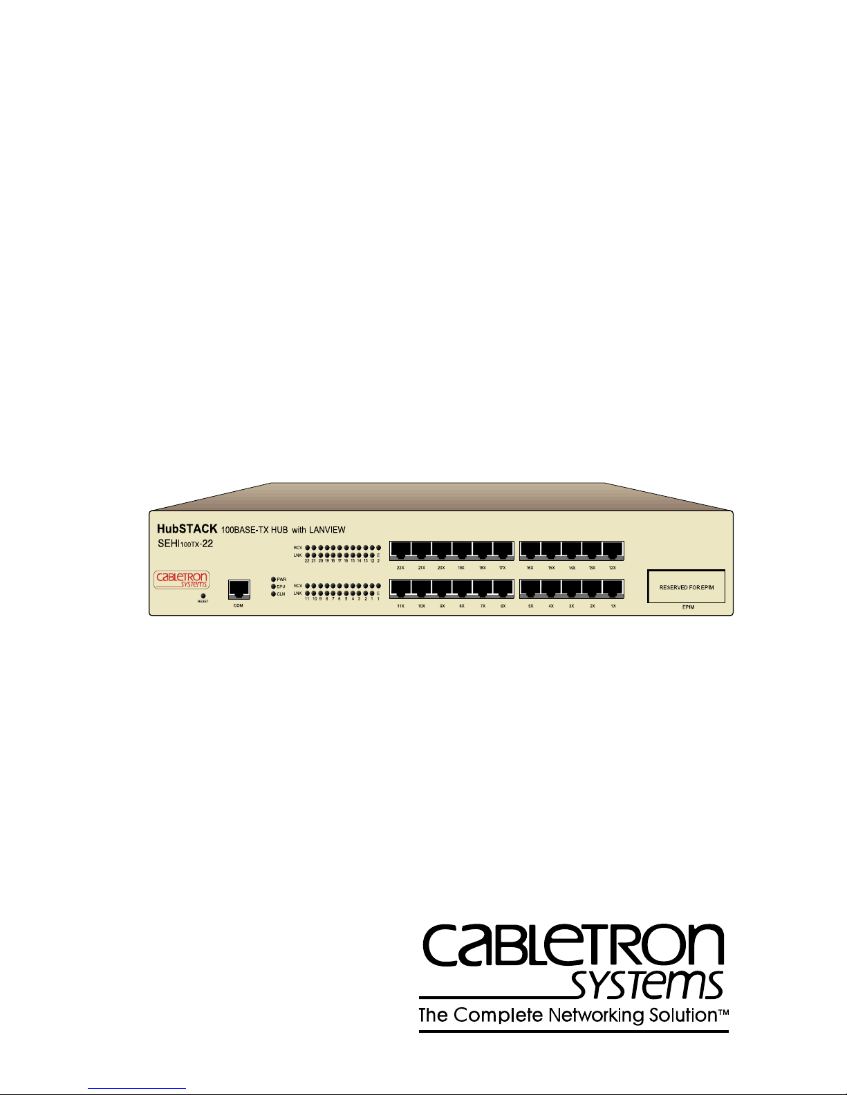
Welcome to the Cabletron Systems
Intelligent Stackable Hub User’s Guide
SEHI100TX-22 100BASE-T
. This manual provides
installation instructions, troubleshooting, and reference information for
the SEHI100TX-22.
The term SEHI (Stackable Ethernet Hub with Intelligence) is
NOTE
used throughout this manual when describing the features and
functions of the SEHI100TX-22.
1.1 USING THIS MANUAL
Read through this manual to gain an understanding of the features and
capabilities of the SEHI. A general knowledge of Ethernet and IEEE
802.3u type data communications networks and their physical layer
components is helpful when installing the SEHI.
Chapter 1,
Introduction
objectives and conventions of this manual. This chapter also provides
information about how to get help and concludes with a list of related
manuals.
, outlines the contents and describes the
Chapter 2,
SEHI Features and Options
, briefly describes SEHI features
and provides information about available options.
Chapter 3,
Installation Requirements and Specifications
, provides
installation requirements, network guidelines, and SEHI specifications.
Chapter 4,
Installation
, contains instructions for installing the SEHI as a
stackable or standalone hub.
Chapter 5,
Connecting to the Network
, explains how to connect the
SEHI to the network using the various media types.
Chapter 6,
Troubleshooting
, describes how to use the LANVIEW LEDs
to troubleshoot network problems.
SEHI100TX User’s Guide 1-1
Chapter 1:
Introduction
Chapter 7,
Local Management
, describes how to use SEHI Local
Management screens and the available commands.
Appendix A,
EPIM Specifications
, provides specifications, cabling
information, and switch settings for the Ethernet Port Interface Modules.
Appendix B,
Image File Download Using OID Strings
, provides
instructions for setting up a TFTP server and downloading an image file
to the SEHI by setting specific MIB OID strings.
1.2 DOCUMENT CONVENTIONS
The following conventions are used throughout this document:
:
Note
symbol. Calls the reader’s attention to any item of
NOTE
information that may be of special importance.
TIP
!
CAUTION
WARNING
Tip
symbol. Conveys helpful hints concerning procedures or
actions.
Caution
damage to the equipment.
Electrical Hazard Warning
that could result in personal injury or death due to an electrical
hazard.
Warning
personal injury or death.
symbol. Contains information essential to avoid
symbol. Warns against an action
symbol. Warns against an action that could result in
1-2 SEHI100TX User’s Guide

Getting Help
1.3 GETTING HELP
If you need additional support related to this device, or if you have any
questions, comments, or suggestions concerning this manual, contact
Cabletron Systems Technical Support:
Phone (603) 332-9400
Monday – Friday; 8 A.M. – 8 P.M. Eastern Time
CompuServe GO CTRON from any ! prompt
Internet mail support@ctron.com
FTP ctron.com (134.141.197.25)
Login
Password
BBS (603) 335-3358
Modem setting 8N1: 8 data bits, 1 stop bit, No parity
anonymous
your email address
For additional information about Cabletron Systems products, visit our
World Wide Web site: http://www .cabletron.com/
Before calling Cabletron Systems Technical Support, have the following
information ready:
• A description of the failure
• A description of any action(s) already taken to resolve the problem
(e.g., changing mode switches, rebooting the unit, etc.)
• A description of your network environment (layout, cable type, etc.)
• Network load and frame size at the time of trouble (if known)
• The serial and revision numbers of all Cabletron Systems products in
the network
• The device history (i.e., have you returned the device before, is this a
recurring problem, etc.)
• Any previous Return Material Authorization (RMA) numbers
SEHI100TX User’s Guide 1-3

Chapter 1:
Introduction
1.4 RELATED MANUALS
Use the Cabletron Systems
SEH100TX-22 100BASE-T User’s Guide
supplement the procedures and other technical data provided in this
manual. The procedures contained in the
User’s Guide
are referenced where appropriate, but not repeated in this
SEH100TX-22 100BASE-T
manual.
to
1-4 SEHI100TX User’s Guide
CHAPTER 2
SEHI FEATURES AND OPTIONS
This chapter provides an overview of the SEHI and contains sections
detailing features and available options.
The terms SEHI (Stackable Ethernet Hub with Intelligence) and
NOTE
HubSTACK 100BASE-TX HUB WITH LANVIEW®
SEHI100TX-22
SEH (Stackable Ethernet Hub) are used throughout this
manual when describing the features and functions of the
SEHI100TX-22 and the SEH100TX-22.
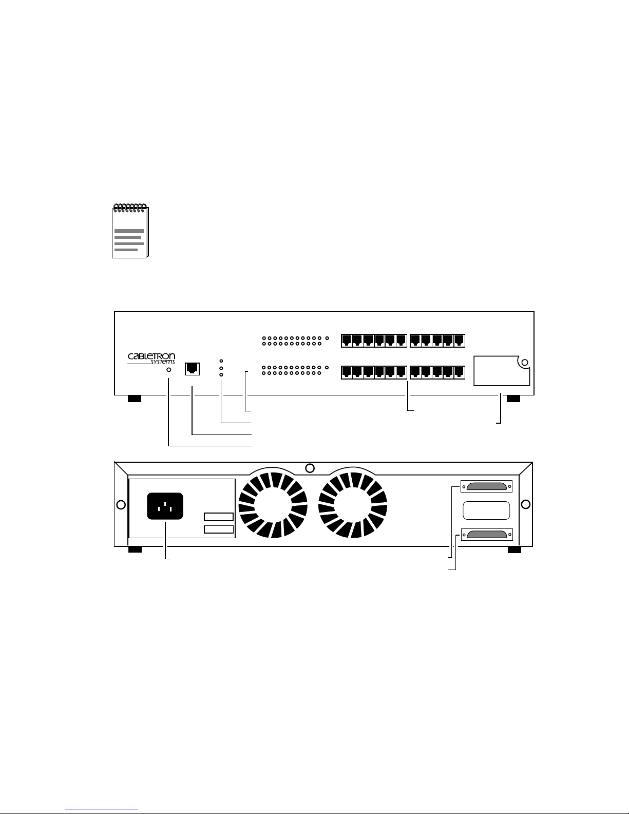
FRONT VIEW
RESET
COM
PWR
CPU
CLN
RCV
LNK
22 21 20 19 18 17 16 15 14 13 12
RCV
LNK
11 10 9 8 7 6 5 4 3 2 1
A
22X 21X 20X 19X 18X 17X
E
1
11X 10X 9X 8X 7X 6X
16X 15X 14X 13X 12X
5X 4X 3X 2X 1X
EPIM 1
SEHI100TX-22 100BASE-T HUB WITH LANVIEW®
SN
NET.
ADD.
Power Supply
Port Status LEDs
System LEDs
COM Port
RESET Button
Interconnect Bus "OUT" Port
Interconnect Bus "IN" Port
Network Ports 1-22
EPIM Slot
SEH100TX INTERCONNECT
OUT
IN
REAR VIEW
Figure 2-1 The SEHI100TX-22
2.1 SEHI OVERVIEW
The SEHI100TX-22 is an intelligent repeating hub providing 22 RJ45
ports and one Ethernet Port Interface Module (EPIM) port on the front
panel for network connections. The SEHI has two rear panel HubSTACK
Interconnect Bus ports for stackable connections. The SEHI100TX-22
can manage up to four of Cabletron Systems SEH100TX-22
non-intelligent stackable hubs.
1511_18
SEHI100TX User’s Guide 2-1

Chapter 2:
!
CAUTION
SEHI Features and Options
The SEHI100TX-22 operates in a 100BASE-T Ethernet
network. This product will NOT operate in a 10BASE-T
environment. Connect the SEHI100TX-22 and SEH100TX-22
only to similar 100BASE-T products.
The SEHI100TX-22 supports the EPIM-100TX, EPIM-100FX,
and the EPIM-100FMB. No other Cabletron Systems EPIMs
operate in this device.
2.2 SEHI FEATURES
The SEHI operating features are as follows:
Repeater Functionality
The SEHI fully conforms to the IEEE 802.3u Repeater specifications. The
SEHI transmits retimed data packets, regenerates the preamble, extends
fragments, and arbitrates collisions.
The SEHI100TX-22 meets IEEE 802.3u Repeater Class I standards.
Class I standards allow one repeater between any two Data Terminal
Equipment (DTE) devices within a single collision domain (network).
The SEHI automatically partitions problem segments, and reconnects
repaired segments to the network. This feature minimizes the impact on
network operation resulting from a problem on one segment by isolating
the problem segment. Only devices on the problem segment are affected.
When the problem is solved, the SEHI automatically reconnects the
isolated segment to the network.
Polarity Detection and Correction
Each twisted pair port on the SEHI incorporates a polarity detection and
correction feature that allows the SEHI to pass data regardless of the
polarity of the twisted pair segment’s receive link.
FLASH EEPROMs
The SEHI uses FLASH EEPROMs that allow the downloading of new
and updated firmware using Cabletron Systems SPECTRUM Element
Manager/Windows or any device using BOOTP or TFTP protocols.
2-2 SEHI100TX User’s Guide

Stackable Capabilities
LANVIEW LEDs
Cabletron Systems LANVIEW status monitoring and diagnostics system
is a troubleshooting tool that helps in diagnosing power failures,
collisions, cable faults, and link problems. The LANVIEW LEDs are
conveniently located on the SEHI front panel.
RESET Button
Resetting the hub with the front panel RESET Button reboots the SEHI
and initializes the processor . Resetting the SEHI also resets all of the SEH
non-intelligent hubs in the stack.
Local Management
Manage the SEHI and its attached segments through Local Management
on the SEHI. Local Management provides full packet and error statistics
for the entire stack, individual device, or individual port. Access Local
Management by attaching a DEC VT320 terminal or a PC using VT320
emulation software to the RJ45 COM port on the SEHI. Cabletron
Systems provides a UTP console cable with RJ45 connectors at each end,
adapters for DB9 or DB25 connections and an instruction sheet with
adapter pinout information with the SEHI. Chapter 7,
Management
, provides detailed information on setting up and managing
Local
your network through Local Management.
2.3 STACKABLE CAPABILITIES
The SEHI100TX-22 intelligent hub is designed to manage a stack of up to
four Cabletron Systems SEH100TX-22 non-intelligent hubs. The SEHI is
placed at the bottom of the stack. It manages all SEH hubs in the stack
and provides full packet and error statistics for the entire stack, indi vidual
device, or individual port.
Stack up to four SEH non-intelligent hubs with one SEHI using the
Cabletron Systems external HubSTACK Interconnect cables provided
with each SEH. Stackable configurations make it possible to maintain
only one IEEE repeater hop while providing up to 120 ports. Hubs can be
added or removed from the stack without ha ving to power do wn the entire
stack.
SEHI100TX User’s Guide 2-3

Chapter 2:
SEHI Features and Options
2.4 RACK MOUNTING CAPABILITIES
The SEHI can be installed in a 19-inch rack. Cabletron Systems provides
brackets and mounting screws with the SEHI. See Chapter 4,
Installation
, for complete rack mounting instructions.
2.5 REMOTE NETWORK MANAGEMENT
Manage the SEHI remotely with any SNMP network management
system. Cabletron Systems offers the following remote management
packages:
• Cabletron Systems SPECTRUM
• Cabletron Systems SPECTRUM Element Manager/Windows
• Cabletron Systems Remote SPECTRUM Portable Management
Applications
• Third Party SNMP compliant Network Management Packages
2.6 OPTIONAL EPIMS
EPIMs are not included with the SEHI, but can be purchased separately
from Cabletron Systems.
EPIMs enable the expansion of a network through different types of
media. Cabletron Systems offers three optional EPIMs for the
SEHI100TX-22 and the SEH100TX-22 as shown in Table 2-1.
Table 2-1 100BASE-TX/FX/FMB EPIMs
EPIM Media Type Connector
EPIM-100TX Category 5 UTP Cable RJ45
EPIM-100FX Multimode Fiber Optic Cable SC
EPIM-100FMB for
buffered uplinks
Multimode Fiber Optic Cable SC
2-4 SEHI100TX User’s Guide

CHAPTER 3
INSTALLATION REQUIREMENTS
AND SPECIFICATIONS
This chapter describes cabling requirements, network guidelines, and
operating specifications for the SEHI100TX-22.
The network must meet the requirements and conditions
!
CAUTION
3.1 CABLE SPECIFICATIONS
The front panel SEHI100TX-22 network ports support Category 5
Unshielded Twisted Pair (UTP) cabling. Ethernet Port Interface Modules
(EPIMs) expand the network using UTP (EPIM-100TX) or multimode
fiber optic (EPIM-100FX or EPIM-100FMB) cabling. For information
concerning the three EPIM types, refer to Appendix A. The rear panel
Interconnect Bus ports support Cabletron Systems Interconnect cables for
stackable applications.
specified in this chapter to obtain satisfactory performance from
this equipment. Failure to follow these guidelines could result in
poor network performance.
Take care in planning and preparing the network cabling and connections.
The quality of the connections and the length of cables are critical factors
in determining the reliability of the network. The following sections
describe specifications for each media type.
3.1.1 HubSTACK Interconnect Cable Requirements
Attach the SEHI to the stacked SEH modules with the HubSTACK
Interconnect cables provided with each SEH and available only from
Cabletron Systems (P/N 9380209). The cable attaches to the SEHI rear
panel bus “OUT” port. The SEHI must be placed at the bottom of the
stack. Stack up to four SEH hubs together with one SEHI.
SEHI100TX User’s Guide 3-1

Chapter 3: Installation Requirements and Specifications
3.1.2 UTP Cable Specifications
The device at the other end of the twisted pair segment must meet IEEE
802.3u 100BASE-T specifications. When connecting a 100BASE-TX
Twisted Pair Segment to the SEHI twisted pair network ports and the
EPIM-100TX module, the network must meet the following
requirements:
Length
The IEEE 802.3u 100BASE-T standard requires that 100BASE-TX
devices be able to transmit over a 100 meter (328 foot) link using
Category 5 UTP wire. The cable used must meet the Horizontal
requirements and 90-meter length limitations. Patch cable should be used
on each end of the Horizontal wire to make connections to punch down
blocks, panels, and other connecting devices. The combined lengths of the
patch cords must not exceed 10 meters so the total segment length does
not exceed 100 meters (328 feet).
Category 5 cables are marked on the cable jacket as Cat 5, Category 5,
Level 5, Level V, or an equivalent.
Impedance
UTP cables typically have an impedance of between 85 to 110 ohms.
Jitter
Intersymbol interference and reflections cause jitter in the bit cell timing,
resulting in data errors. A 100B ASE-TX link must not generate more than
1.4 ns of jitter. If the cable meets the impedance requirements for a
100BASE-TX link, jitter should not be a concern.
Crosstalk
Crosstalk is caused by signal coupling between the different cable pairs
contained within a multi-pair cable bundle. 100B ASE-TX transceiv ers are
designed so that the user does not need to be concerned about cable
crosstalk, provided the cable meets all other requirements.
Noise
Noise is caused by either crosstalk or externally induced impulses.
Impulse noise may cause data errors if the impulses occur at very specific
times during data transmission. Generally , the user need not be concerned
about noise. If noise-related data errors are suspected, it may be necessary
to either reroute the cable or eliminate the source of the impulse noise.
3-2 SEHI100TX User’s Guide

Cable Specifications
Propagation Delay
Propagation delay is the amount of time it takes data to travel from the
sending device to the receiving device. Total propagation delay allowed
for the network is 256 bit times (2.56 µs) in one direction (5.12 µs round
trip). If the total propagation delay between any two nodes on the network
exceeds 2.56 µs, then use bridges or other devices to further segment the
network.
Temperature
The attenuation of PVC insulated cable varies significantly with
temperature. At temperatures greater than 40°C (104°F), Cabletron
Systems recommends the use of plenum-rated cables to ensure that cable
attenuation remains within specification.
3.1.3 Multimode Fiber Optic Cable Specifications
The SEHI supports the Cabletron Systems EPIM-100FX and
EPIM-100FMB. These EPIMs meet IEEE 802.3u standards. When
connecting a fiber optic segment to the SEHI EPIM-100FX or
EPIM-100FMB module, the network must meet the following
requirements:
Cable Loss
T est the fiber optic cable with a fiber optic attenuation test set adjusted for
an 850 nm wavelength. This test verifies that the signal loss in a cable is
within an acceptable level. The maximum loss for a multimode fiber optic
cable is 11.0 dB.
Fiber Optic Budget and Propagation Delay
Determine the maximum fiber optic cable length by calculating the fiber
optic budget delay and total network propagation before fiber optic cable
runs are incorporated in any network design.
Fiber optic budget is the combination of the optical loss due to the fiber
optic cable, in-line splices, and fiber optic connectors.
SEHI100TX User’s Guide 3-3

Chapter 3: Installation Requirements and Specifications
Propagation delay (collision delay) is the amount of time it takes data to
travel from the sending device to the receiving device. Total propagation
delay allowed for the entire network is 256 bit times (2.56 µs) in one
direction (5.12 µs round trip). If the total propagation delay between any
two nodes on the network exceeds 2.56 µs, then use bridges or other
devices to further segment the network.
3.2 NETWORK CABLE LENGTHS
This section details the maximum network cable lengths specified by the
IEEE 802.3u standard for a Class I repeater. As stated previously, the
physical size of the network is limited primarily by propagation delay.
The round trip delay cannot exceed 512 bit times or 5.12 µs.
A stack of five SEH hubs or four SEH hubs and one SEHI hub
NOTE
is equivalent to one repeater.
A 100BASE-T network might use all UTP links, all fiber links or a
combination of both. Figure 3-1 shows a simplified example of a network
with one Class I repeater. Link segments A and B represent the longest
links in the network. In this case, if both segment A and segment B are
UTP, each segment may be up to 100 meters long for a maximum network
length of 200 meters. If segment A is UTP and segment B is fiber optics,
the maximum length of the network is 263 meters (with a maximum UTP
segment length of 100 meters). If both segments A and B are multimode
fiber optics, the maximum length is 274 meters.
If a buffered uplink (EPIM-100FMB) is used, the collision domain is
stopped at the EPIM slot. This allows a full length fiber optic link of 400
meters to be used as an uplink while maintaining 100-meter UTP and
400-meter fiber optic lengths to desktops. So if segment A, shown in
Figure 3-1, is UTP and segment B is fiber optics, the maximum length of
the network is 500 meters. If both segments are fiber optics, the maximum
length is 800 meters.
3-4 SEHI100TX User’s Guide
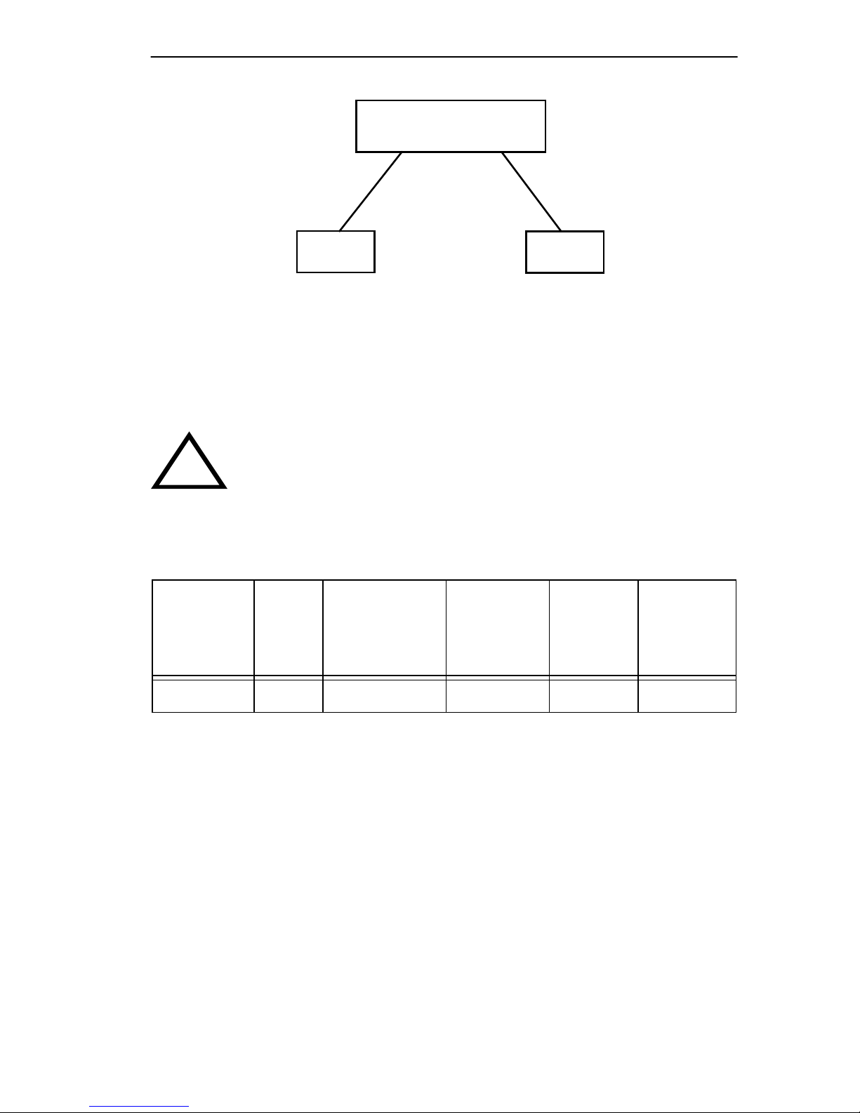
SEHI100TX-22
Repeater
Network Cable Lengths
A
DTE
Figure 3-1 Class I Network
B
DTE
Table 3-1 summarizes the maximum link lengths for each type and
combination of cable when used with a Class I repeater.
The maximum length of an individual UTP segment may be no
!
CAUTION
Number
of
Repeaters
more than 100 meters.
Table 3-1 Maximum Class I Network Cable Length
UTP
UTP &
Multimode
Fiber Optics
Multimode
Fiber
Optics
UTP &
Buffered
EPIM
Fiber
Optics &
Buffered
EPIM
1 200 m 263 m 274 m 500 m 800 m
SEHI100TX User’s Guide 3-5
Chapter 3: Installation Requirements and Specifications
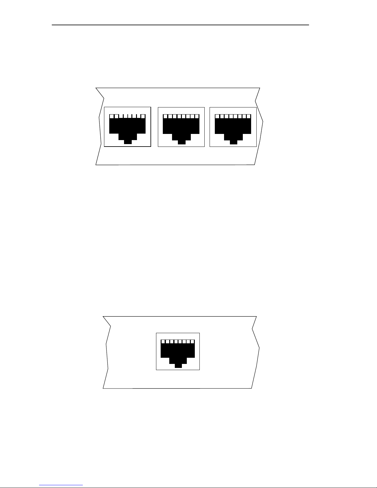
3.3 NETWORK PORT SPECIFICATIONS
The SEHI network ports use shielded RJ45 connectors that support UTP
cabling. Figure 3-2 shows the RJ45 pinouts.
1 2 3 4 5 6 7 8
11X
10X
9X
1. Receive + 5. Not Used
2. Receive - 6. Transmit -
3. Transmit + 7. Not Used
4. Not Used 8. Not Used
09162_02
Figure 3-2 RJ45 Network Port Pinouts
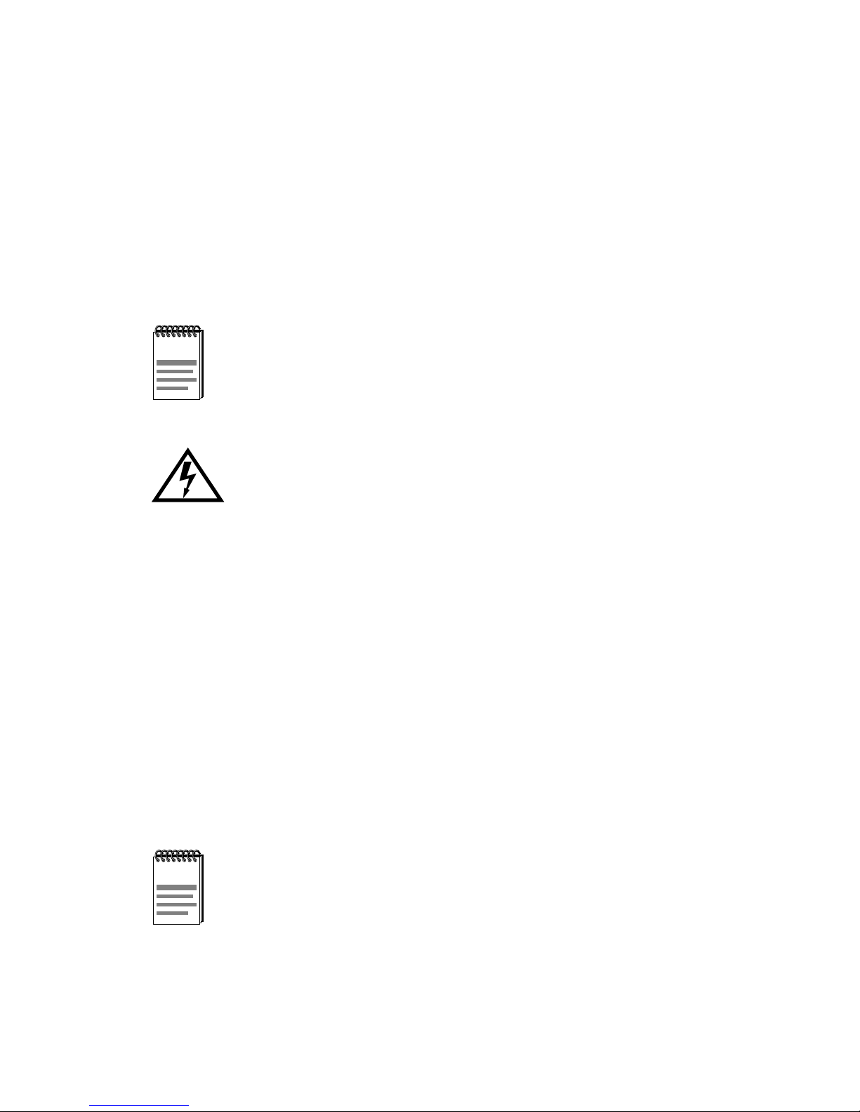
3.4 COM PORT REQUIREMENTS
The RJ45 COM port supports access to a Local Management Console.
The COM port supports a Digital Equipment Corporation VT320 terminal
or PC emulation of the VT320 terminal. Figure 3-3 shows the pinouts for
the RJ45 COM port.
1. Transmit Data
2. Data Carrier Detect
3. Data Set Ready
4. Receive Data
Figure 3-3 RJ45 COM Port Pinouts
3-6 SEHI100TX User’s Guide
1 2 3 4 5 6 7 8
COM
5. Signal Ground
6. Data Terminal Ready
7. Request To Send
8. Clear To Send
1511_15

Operating Specifications
3.5 OPERATING SPECIFICATIONS
The operating specifications for the SEHI100TX-22 are described in this
section. Cabletron Systems reserves the right to change these
specifications at any time without notice.
3.5.1 Power Supply Requirements
The SEHI uses a universal power supply. The input requirements are
listed in Table 3-2.
Table 3-2 Power Supply Requirements
Line Input Range
Volts (V)
100–125 V ac 4.0 A
200–250 V ac 2.0 A
Current
Amperes (A)
Frequency
Hertz (Hz)
50/60 Hz
3.5.2 Environmental Requirements
This section details the environmental requirements of the SEHI.
Operating Temperature: 5°C to 40°C (41°F to 104°F)
Storage Temperature: -30°C to 73°C (-22°F to 164°F)
Operating Humidity: 15% to 90% (non-condensing)
3.5.3 Agency Approvals
The safety , emission, and immunity approv als for the SEHI are detailed in
this section.
Safety
This unit meets the safety requirements of UL 1950, CSA C22.2 No. 950,
IEC 950 and EN 60950.
Emissions
This unit meets the emission requirements of FCC Part 15 Class A,
EN 55022 Class A and VCCI Class I.
SEHI100TX User’s Guide 3-7

Chapter 3: Installation Requirements and Specifications
Immunity
This unit meets the immunity requirements of EN 50082-1 including
IEC 801-2 (ESD), IEC 801-3 (Radiated Susceptibility), and
IEC 801-4 (EFT/B).
3.6 PHYSICAL SPECIFICATIONS
This section details the physical specifications for the SEHI.
Dimensions (H x W x D): 2.8 in x 17.0 in x 13.5 in
(7.2 cm x 43.6 cm x 34.6 cm)
Weight: 7 lb (3.15 kg)
3-8 SEHI100TX User’s Guide
CHAPTER 4
INSTALLATION
This chapter outlines the procedure for attaching the SEHI to the network
as a stackable or standalone device. Ensure that the network meets the
guidelines and requirements outlined in Chapter 3, Installation
Requirements and Specifications, before installing the SEHI.
A single phase grounded power receptacle that meets the
NOTE
requirements listed in Chapter 3 must be located within seven
feet of the installation.
Failure to follow installation instructions may result in an
electrical shock hazard.
4.1 UNPACKING THE SEHI
Unpack the SEHI as follows:
1. Remove the shipping material covering the SEHI in the shipping box.
2. Carefully remove the SEHI from the shipping box and set it aside to
prevent damage.
3. Visually inspect the SEHI. If there are any signs of damage, contact
Cabletron Systems Technical Support immediately. Refer to
Section 1.3 for instructions on getting help.
4. Read the SEHI Release Notes included in the shipping box.
Cabletron Systems includes a 3 1/2-inch disk with the
NOTE
SEHI100TX-22 that contains a backup copy of the FLASH
Firmware Image File. Download the file to the SEHI100TX-22 if
the existing image becomes corrupted. Refer to Appendix B for
detailed download instructions.
SEHI100TX User’s Guide 4-1
 Loading...